CN110986697A - Multifunctional rocket cabin docking vehicle - Google Patents
Multifunctional rocket cabin docking vehicle Download PDFInfo
- Publication number
- CN110986697A CN110986697A CN201911313455.8A CN201911313455A CN110986697A CN 110986697 A CN110986697 A CN 110986697A CN 201911313455 A CN201911313455 A CN 201911313455A CN 110986697 A CN110986697 A CN 110986697A
- Authority
- CN
- China
- Prior art keywords
- driving
- frame
- butt joint
- rolling
- docking
- Prior art date
- Legal status (The legal status is an assumption and is not a legal conclusion. Google has not performed a legal analysis and makes no representation as to the accuracy of the status listed.)
- Pending
Links
Images


Classifications
-
- F—MECHANICAL ENGINEERING; LIGHTING; HEATING; WEAPONS; BLASTING
- F42—AMMUNITION; BLASTING
- F42B—EXPLOSIVE CHARGES, e.g. FOR BLASTING, FIREWORKS, AMMUNITION
- F42B15/00—Self-propelled projectiles or missiles, e.g. rockets; Guided missiles
- F42B15/36—Means for interconnecting rocket-motor and body section; Multi-stage connectors; Disconnecting means
Abstract
The invention relates to the technical field of butt joint of rocket cabin sections, in particular to a multifunctional butt joint vehicle for rocket cabin sections. The device comprises a butt joint driving wheel train, a transfer driving wheel train, a frame, a six-dimensional posture adjusting bracket and an automatic charging mechanism, wherein the butt joint driving wheel train is arranged below the frame and used for driving walking in a butt joint mode; the transfer driving wheel train is arranged below the frame and used for driving to walk in a transfer mode; the six-dimensional attitude adjusting bracket is arranged above the frame and used for realizing the requirement of adjusting the position and the attitude of the cabin section; the automatic charging mechanism is arranged below the frame and used for completing the tight connection of the butt joint vehicle of the rocket cabin section and the ground charging equipment and realizing the current conduction. The invention has high precision, convenient operation and high degree of automation, is powerful for improving the automation, intelligence and unmanned degree of the production line, and greatly contributes to production safety and production efficiency.
Description
Technical Field
The invention relates to the technical field of butt joint of rocket cabin sections, in particular to a multifunctional butt joint vehicle for rocket cabin sections.
Background
The rocket cabin segment butt joint method has gradually evolved from the traditional hoisting butt joint method to a non-hoisting method, and in this context, the organic combination of the two processes of rocket cabin segment transfer and butt joint is a necessary trend in rocket production. The conventional butt-joint vehicle for the rocket cabin section with the rails is difficult to charge and high in rail-changing cost, and the conventional transfer vehicle for the rocket cabin section without the rails is low in precision and difficult to undertake accurate butt-joint work. Therefore, it is necessary to develop a novel multifunctional rocket cabin butt-joint vehicle with high precision and convenient maintenance.
Disclosure of Invention
Aiming at the problems, the invention aims to provide a multifunctional rocket cabin butt joint vehicle, which organically combines a novel tracked multifunctional rocket cabin butt joint vehicle with a trackless cabin transfer vehicle and has important guiding significance for improving the technical level of rocket cabin transfer and butt joint.
In order to achieve the purpose, the invention adopts the following technical scheme:
a multi-functional rocket pod segment docking cart, comprising: the device comprises a frame, a butt joint driving wheel train, a transfer driving wheel train, a six-dimensional posture adjusting bracket and an automatic charging mechanism, wherein the butt joint driving wheel train is arranged below the frame and used for driving to walk in a butt joint mode; the transfer driving gear train is arranged below the frame and used for driving to walk in a transfer mode; the six-dimensional attitude adjusting bracket is arranged above the frame and used for realizing the requirement of cabin position and attitude adjustment; the automatic charging mechanism is arranged below the frame and used for completing the tight connection of the butt joint vehicle of the rocket cabin section and ground charging equipment and realizing current conduction.
The six-dimensional posture adjusting bracket comprises two groups of six-degree-of-freedom adjusting devices which are arranged in front and back, and the six-degree-of-freedom adjusting devices comprise:
the butt joint direction moving mechanism is arranged on the frame and has freedom degree of moving along the longitudinal direction;
two groups of lifting mechanisms are arranged on the butt joint direction moving mechanism and have freedom degree of movement along the height direction;
the transverse moving mechanism is arranged on the two groups of lifting mechanisms and has freedom degree of movement along the transverse direction;
and the rolling mechanism is arranged on the transverse moving mechanism and has the freedom degree of rolling around a horizontal axis.
The butt joint direction moving mechanism comprises a longitudinal moving guide rail, a butt joint direction moving gear, a butt joint direction moving rack, a butt joint direction moving servo motor and a butt joint direction moving sliding plate, wherein the longitudinal moving guide rail and the butt joint direction moving rack are longitudinally arranged on the frame;
the lifting mechanism comprises a lifting support, a guide sleeve, a guide pillar, a lifting plate and a servo electric cylinder, wherein the lifting support is arranged on the butt joint direction motion sliding plate, the servo electric cylinder is arranged on the lifting support, an output shaft is connected with the lifting plate, the guide sleeve is arranged on the lifting support, and the lifting plate is in sliding fit with the guide sleeve through the guide pillar.
The transverse moving mechanism comprises a transverse moving rack, a transverse moving gear, a transverse driving servo motor, a transverse moving guide rail sliding block mechanism, a transverse moving mechanism base and a transverse moving plate, wherein two ends of the transverse moving mechanism base are respectively connected with the two groups of lifting mechanisms, the transverse moving rack and the transverse moving guide rail sliding block mechanism are transversely arranged on the transverse moving mechanism base, the transverse moving plate is connected with the transverse moving guide rail sliding block mechanism, the transverse driving servo motor is arranged on the transverse moving plate, an output shaft is connected with the transverse moving gear, and the transverse moving gear is meshed with the transverse moving rack.
The rolling mechanism comprises a rolling arc guide rail slider mechanism, a rolling driving servo motor, an arc rack, a rolling gear and a rolling supporting plate, wherein the rolling supporting plate is connected with the traversing mechanism through the rolling arc guide rail slider mechanism, the arc rack is arranged at the bottom of the rolling supporting plate, the rolling driving servo motor is arranged on the traversing mechanism, an output shaft is connected with the rolling gear, and the rolling gear is meshed with the arc rack.
The butt joint driving wheel system is arranged at the front end and the rear end of the frame and comprises a plurality of driving wheels and a plurality of driven wheels, and the driving wheels and the driven wheels respectively comprise wheel frames and steel wheel assemblies arranged on the wheel frames; the driving wheel also comprises a servo driving motor which is arranged on the wheel frame and is used for driving the steel wheel assembly to rotate.
The transfer driving wheel train is arranged on the frame and comprises a lifting wheel set and a driving wheel set, wherein the driving wheel set is arranged in the middle of the frame; the lifting wheel set is arranged on two sides of the driving wheel set.
The lift wheelset includes universal wheelset, pneumatic cylinder actuating mechanism I, guide rail slider mechanism I and universal wheel mounting panel, wherein the universal wheel mounting panel pass through guide rail slider mechanism I with connected to the vehicle frame, universal wheelset set up in on the universal wheel mounting panel, pneumatic cylinder actuating mechanism I set up in on the frame, and the output with the universal wheel mounting panel is connected.
The driving wheel group includes pneumatic cylinder actuating mechanism II, all-round steering wheel, relocation mechanism, rail block mechanism II and steering wheel mounting panel, wherein the steering wheel mounting panel pass through rail block mechanism II with connected to the frame, all-round steering wheel passes through the relocation mechanism to be installed the bottom of steering wheel mounting panel, pneumatic cylinder actuating mechanism II is installed on the frame, and the output with the steering wheel mounting panel is connected.
The automatic charging mechanism comprises a mounting plate, a charging brush block mounting seat, a clamping spring and a charging brush block, wherein the mounting plate is mounted at the bottom of the frame, the charging brush block is mounted on the mounting plate through the charging brush block mounting seat, and the charging brush block is tightly connected with ground charging equipment; and a clamping spring is arranged between the charging brush block and the charging brush block mounting seat.
The invention has the advantages and beneficial effects that:
the invention organically combines the butt joint and the transfer of the rocket cabin section, and improves the working efficiency of the transfer butt joint of the large cabin section.
The invention reduces the labor force of the butt joint link and realizes automation.
The invention greatly simplifies the maintenance of the novel rail-guided multifunctional rocket cabin butt-joint vehicle and saves time and labor.
Drawings
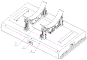
FIG. 1 is a schematic structural view of a multi-functional rocket cabin docking cart according to the present invention;
FIG. 2 is a layout diagram of a walking drive system of the multifunctional rocket cabin docking car of the present invention;
FIG. 3 is a schematic structural diagram of a driving wheel in the docking driving wheel train of the present invention;
FIG. 4 is a schematic view of the structure of the driven wheel in the butt drive train of the present invention;
FIG. 5 is a schematic structural diagram of a lifting wheel set in the transfer drive train of the present invention;
FIG. 6 is a schematic structural view of a drive wheel set in the transfer drive train of the present invention;
FIG. 7 is a schematic view of the six-dimensional pose adjustment bracket of the present invention;
FIG. 8 is a schematic structural view of the elevating mechanism and the docking direction moving mechanism of the present invention;
FIG. 9 is a schematic structural view of the rolling mechanism and the traversing mechanism of the present invention;
fig. 10 is a schematic structural diagram of an automatic charging mechanism according to the present invention.
In the figure: 1 is a butt joint driving wheel train, 2 is a transfer driving wheel train, 3 is a vehicle frame, 4 is a six-dimensional posture adjusting bracket, 8 is an automatic charging mechanism, 9 is a driving wheel, 10 is a driven wheel, 11 is a wheel frame, 12 is a steel wheel component, 13 is a servo driving motor, 14 is a lifting wheel group, 15 is a driving wheel group, 16 is a universal wheel group, 17 is a hydraulic cylinder driving mechanism I, 18 is a guide rail slide block mechanism I, 19 is a universal wheel mounting plate, 20 is a hydraulic cylinder driving mechanism II, 21 is an omnibearing steering wheel, 22 is a floating mechanism, 23 is a guide rail slide block mechanism II, 24 is a steering wheel mounting plate, 25 is a rolling mechanism, 26 is a lifting mechanism, 27 is a butt joint direction moving mechanism, 28 is a transverse moving mechanism, 29 is a longitudinal moving guide rail, 30 is a mounting plate, 31 is a charging brush block mounting seat, 32 is a clamping spring, 33 is a charging brush block, 34 is a rolling guide rail arc slide block mechanism, 35 is a rolling driving servo motor, an arc rack 36, a rolling gear 37, a transverse rack 38, a transverse motion gear 39, a transverse driving servo motor 40, a transverse motion guide rail and slider mechanism 41, a guide sleeve 42, a guide post 43, a servo electric cylinder 44, a butt joint direction motion gear 45, a butt joint direction motion rack 46, a butt joint direction motion servo motor 47, a transverse motion mechanism base 50, a transverse motion plate 51 and a rolling supporting plate 52.
Detailed Description
In order to make the objects, technical solutions and advantages of the present invention more apparent, the present invention will be described in detail with reference to the accompanying drawings and specific embodiments.
As shown in fig. 1-2, the invention provides a multifunctional rocket cabin docking cart, comprising: the device comprises a butt joint driving gear train 1, a transfer driving gear train 2, a frame 3, a six-dimensional posture adjusting bracket 4 and an automatic charging mechanism 8, wherein the butt joint driving gear train 1 is arranged below the frame 3 and used for driving and walking in a butt joint mode; the transfer driving wheel train 2 is arranged below the frame 3 and is used for driving and walking in a transfer mode; the six-dimensional attitude adjusting bracket 4 is arranged above the frame 3 and is used for realizing the requirement of cabin position and attitude adjustment; the automatic charging mechanism 8 is arranged below the frame 3 and used for completing the tight connection between the butt joint vehicle of the rocket cabin section and ground charging equipment and realizing current conduction.
As shown in fig. 3 and 4, the butt-joint driving gear train 1 is arranged at the front end and the rear end of the frame 3, and includes a plurality of driving wheels 9 and a plurality of driven wheels 10, and each of the driving wheels 9 and the driven wheels 10 includes a wheel carrier 11 and a steel wheel assembly 12 arranged on the wheel carrier 11; the driving wheel 9 further comprises a servo driving motor 13 mounted on the wheel frame 11 and used for driving the steel wheel assembly 12 to rotate.
In the embodiment of the present invention, the docking driving wheel system 1 comprises eight steel wheel assemblies 12, wherein four steel wheel assemblies 12 at two ends of the frame 3 are provided with driving mechanisms to provide power, i.e. the four steel wheel assemblies 12 are driving wheels, and the other four wheels are driven wheels. Two sides of the steel wheel are provided with flanges to prevent the vehicle body from separating from the track.
As shown in fig. 2, the transfer driving wheel system 2 is disposed on the frame 3, and includes a lifting wheel set 14 and a driving wheel set 15, wherein the driving wheel set 15 is disposed at the middle position of the frame 3, and the lifting wheel set 14 is disposed at two sides of the driving wheel set 15.
As shown in fig. 5, the lifting wheel set 14 includes a universal wheel set 16, a hydraulic cylinder driving mechanism i 17, a rail slider mechanism i 18 and a universal wheel mounting plate 19, wherein the universal wheel mounting plate 19 is connected with the frame 30 through the rail slider mechanism i 18, the universal wheel set 16 is disposed on the universal wheel mounting plate 19, the hydraulic cylinder driving mechanism i 17 is disposed on the frame 3, and the output end of the hydraulic cylinder driving mechanism i 17 is connected with the universal wheel mounting plate 19.
As shown in fig. 6, the driving wheel set 15 includes a hydraulic cylinder driving mechanism ii 20, an omnidirectional steering wheel 21, a floating mechanism 22, a rail slider mechanism ii 23, and a steering wheel mounting plate 24, wherein the steering wheel mounting plate 24 is connected to the frame 3 through the rail slider mechanism ii 23, the omnidirectional steering wheel 21 is mounted at the bottom of the steering wheel mounting plate 24 through the floating mechanism 22, and the hydraulic cylinder driving mechanism ii 20 is mounted on the frame 3, and the output end is connected to the steering wheel mounting plate 24.
In the embodiment of the invention, the transfer driving wheel train 2 comprises two lifting wheel sets 14 and one driving wheel set 15, wherein each lifting wheel set 14 comprises two universal wheel sets 16, hydraulic cylinders are arranged above the lifting wheel set 14 and the driving wheel set 16, when the butt joint mode of the novel multifunctional rocket cabin butt joint vehicle is converted into the transfer mode from the butt joint mode, the hydraulic cylinders arranged above the lifting wheel sets 14 descend to bear the load of a vehicle body, and the hydraulic cylinders arranged above the driving wheel sets 15 descend to provide driving force but not bear the load.
The universal wheel set 16 adopts double solid polyurethane material and effective damping design, and four universal wheels in the two lifting wheel sets support the vehicle body at four points to form a stable supporting form. The universal wheel assembly is specially made, has large bearing capacity and can flexibly rotate by 360 degrees.
When the butt joint mode of the multifunctional rocket cabin butt joint vehicle is converted into a transfer mode, the butt joint driving gear train 1 is separated from the butt joint track; the driving wheel set 15 descends under the driving of the hydraulic cylinder driving mechanism II 20 to provide ground walking driving force for the butt joint vehicle, and the omnibearing steering wheel 21 is installed on the steering wheel installation plate through the clamping spring floating mechanism 22, so that the wheel pressure and the traction force of the driving wheel are always stable and unchanged. At this time, the vehicle body is driven by the driving wheel set 15 to travel along the ground, and the lifting wheel set 14 only serves as a follow-up wheel to assist in supporting and guiding the vehicle body.
As shown in fig. 1, the six-dimensional attitude adjusting bracket 4 includes two sets of six-degree-of-freedom adjusting devices disposed in front and back, and the two sets of six-degree-of-freedom adjusting devices are disposed in front and back, and are slidably disposed on the frame 3 in the front and back directions, each of the six-degree-of-freedom adjusting devices includes four active degree-of-freedom adjusting mechanisms moving in the rolling, lifting, butting direction and the traversing direction, and two follow-up degree-of-freedom adjusting mechanisms moving in the yawing and pitching directions, and the two sets of six-degree-of-freedom adjusting devices coordinate to perform the six-degree-of.
As shown in fig. 7, the six-degree-of-freedom adjusting device includes a rolling mechanism 25, a lifting mechanism 26, a docking direction moving mechanism 27, and a traversing mechanism 28, wherein the docking direction moving mechanism 27 is disposed on the frame 3 and has a degree of freedom to move in the longitudinal direction; two sets of lifting mechanisms 26 are arranged on the butt joint direction moving mechanism 27 and have freedom of moving along the height direction; the transverse moving mechanism 28 is arranged on the two groups of lifting mechanisms 26 and has freedom degree of movement along the transverse direction; the rolling mechanism 25 is provided on the traverse mechanism 28, and has a degree of freedom of rolling about a horizontal axis.
As shown in fig. 8, the docking direction moving mechanism 27 includes a longitudinal moving guide 29, a docking direction moving gear 45, a docking direction moving rack 46, a docking direction moving servo motor 47 and a docking direction moving slide plate, wherein the longitudinal moving guide 29 and the docking direction moving rack 46 are longitudinally disposed on the carriage 3, the docking direction moving slide plate is slidably connected to the longitudinal moving guide 29, the docking direction moving servo motor 47 is disposed on the docking direction moving slide plate, and the output shaft is provided with the docking direction moving gear 45, and the docking direction moving gear 45 is engaged with the docking direction moving rack 46. The docking direction movement servo motor 47 drives the docking direction movement gear 45 to rotate, and drives the docking direction movement slide plate to slide along the longitudinal movement guide rail 29 because the docking direction movement gear 45 is meshed with the docking direction movement rack 46.
The lifting mechanism 26 comprises a lifting support, a guide sleeve 42, a guide post 43, a lifting plate and a servo electric cylinder 44, wherein the lifting support is arranged on the butt joint direction movement sliding plate, the servo electric cylinder 44 is arranged on the lifting support, an output shaft is connected with the lifting plate, the guide sleeve 42 is arranged on the lifting support, and the lifting plate is in sliding fit with the guide sleeve 42 through the guide post 43.
As shown in fig. 9, the traverse mechanism 28 includes a traverse rack 38, a traverse gear 39, a traverse driving servo motor 40, a traverse guide slider mechanism 41, a traverse mechanism base 50, and a traverse plate 51, wherein both ends of the traverse mechanism base 50 are respectively connected to two sets of lifting mechanisms 26, the traverse rack 38 and the traverse guide slider mechanism 41 are laterally disposed on the traverse mechanism base 50, the traverse plate 51 is connected to the traverse guide slider mechanism 41, the traverse driving servo motor 40 is disposed on the traverse plate 51, an output shaft is connected to the traverse gear 39, and the traverse gear 39 is engaged with the traverse rack 38. The transverse driving servo motor 40 drives the transverse moving gear 39 to rotate, thereby driving the transverse moving plate 51 to slide along the transverse moving guide rail slider mechanism 41.
As shown in fig. 9, the rolling mechanism 25 includes a rolling arc guide rail slider mechanism 34, a rolling driving servo motor 35, an arc rack 36, a rolling gear 37 and a rolling pallet 52, wherein the rolling pallet 52 is connected to the traverse plate 51 of the traverse mechanism 28 through the rolling arc guide rail slider mechanism 34, the arc rack 36 is disposed at the bottom of the rolling pallet 52, the rolling driving servo motor 35 is disposed on the traverse mechanism 28, the output shaft is connected to the rolling gear 37, and the rolling gear 37 is engaged with the arc rack 36. The roll drive servo motor 35 drives the roll gear 37 to rotate, thereby driving the roll platform 52 to rotate along the roll arc rail slider mechanism 34.
As shown in fig. 10, the automatic charging mechanism 8 includes a mounting plate 30, a charging brush block mounting seat 31 and a charging brush block 33, wherein the mounting plate 30 is mounted at the bottom of the vehicle frame 3, the charging brush block 33 is mounted on the mounting plate 30 through the charging brush block mounting seat 31, and the charging brush block 33 is tightly connected with the ground charging device to realize current conduction.
Further, a spring 32 is interposed between the charging brush block 33 and the charging brush block attachment seat 31.
In the butt joint operating condition, the butt joint car is in the rail state of traveling, transports the pneumatic cylinder of drive train 2 and is in the shrink state, transports drive train 2 and is in the suspension state, and the automobile body traveles on the steel track, and among its eight steel wheels of four groups, four steel wheels of front and back two sets of total have actuating mechanism, drive the automobile body, and two sets of actuating mechanism make the automobile body can travel in a flexible way on the track.
When the butt joint vehicle faces the requirements of transportation, charging, maintenance and the like of the cabin section, the hydraulic cylinder presses down the wheels of the ground walking mechanism, the butt joint vehicle is converted into a transportation mode, and the butt joint vehicle can freely run to a specified maintenance place without additionally paving a track.
The working principle of the invention is as follows:
the lifting mechanism 26 completes a guiding function by using a guide sleeve 42 and guide post 43 structure, and is matched with a servo electric cylinder 44 to complete driving, the front and rear groups of six-dimensional attitude adjusting brackets 4 are provided with lifting motion mechanisms, a mechanism size model is established, the relation between the motion value of the freedom degree of the front and rear lifting motion and the true pitching value of the cabin section is accurately established through model simulation and product comparison, the purpose of accurately adjusting the pitching angle of the cabin section is achieved, when the lifting mechanisms 26 in the two groups of six-dimensional attitude adjusting brackets 4 move synchronously, the cabin section integrally completes lifting motion, and the accurate coordination control of the front and rear mechanisms is the basis of accurate adjustment of the freedom degree; the docking direction moving mechanism 27 adopts a gear and rack structure as a power driving mechanism, is driven by a docking direction movement servo motor 47, uses the longitudinal moving guide rail 29 as a precise guiding mechanism for movement, and has no position difference because the docking movement is synchronous.
The front and rear groups of six-dimensional attitude adjusting brackets 4 are provided with rolling mechanisms 25 and transverse moving mechanisms 28, a mechanism size model is established, the relationship between the motion numerical values of the front and rear rolling and translation motion freedom degrees and the actual numerical value of cabin yawing is accurately established through model simulation and product comparison, and the purpose of accurately adjusting the cabin yawing angle, the yawing distance and the transverse moving distance is achieved.
The yaw angle change of the whole cabin product is realized by the translation position difference of the transverse moving mechanisms 28 in the front and rear groups of six-dimensional attitude adjusting brackets 4, namely, a yaw follow-up degree of freedom adjusting mechanism, and the pitching change of the whole cabin product is realized by the height difference of the lifting mechanisms 25 in the front and rear groups of six-dimensional attitude adjusting brackets 4, namely, a pitching follow-up degree of freedom adjusting mechanism.
The invention has two sets of running driving mechanisms of a butt joint driving gear train and a transfer driving gear train, the butt joint driving gear train is adopted during daily butt joint operation, and when cabin transfer, charging, maintenance and other work are carried out, the transfer mechanism is supported by a hydraulic cylinder and is switched from a butt joint mode to a transfer mode. The butt joint driving gear train, the transfer driving gear train and the automatic charging mechanism are all designed in an explosion-proof mode.
The invention combines the functions and advantages of a rail-type rocket cabin segment butt joint vehicle and a trackless rocket cabin segment transfer vehicle, provides a novel rocket cabin segment butt joint vehicle organically combining the butt joint and the transfer of rocket cabin segments, and properly solves the problems that the conventional rail-type rocket cabin segment butt joint vehicle is difficult to charge and high in rail change cost, and the conventional trackless rocket cabin segment transfer vehicle is low in precision and difficult to undertake accurate butt joint work. The invention has high precision, convenient operation and high degree of automation, is powerful for improving the automation, intelligence and unmanned degree of the production line, and greatly contributes to production safety and production efficiency.
The above description is only an embodiment of the present invention, and is not intended to limit the scope of the present invention. Any modification, equivalent replacement, improvement, extension, etc. made within the spirit and principle of the present invention are included in the protection scope of the present invention.
Claims (10)
1. A multi-functional rocket cabin section butt joint car which characterized in that includes:
a frame (3);
the butt joint driving gear train (1) is arranged below the frame (3) and is used for driving to walk in a butt joint mode;
the transfer driving gear train (2) is arranged below the frame (3) and is used for driving and walking in a transfer mode;
the six-dimensional posture adjusting bracket (4) is arranged above the frame (3) and is used for realizing the requirement of cabin position posture adjustment;
and the automatic charging mechanism (8) is arranged below the frame (3) and is used for completing the tight connection of the butt joint vehicle of the rocket cabin section and ground charging equipment so as to realize current conduction.
2. A multifunctional rocket cabin segment docking carriage according to claim 1, characterized in that said six-dimensional attitude-adjusting carriage (4) comprises two sets of six-degree-of-freedom adjusting devices arranged front and back, said six-degree-of-freedom adjusting devices comprising:
a docking direction moving mechanism (27) provided on the carriage (3) and having a degree of freedom of movement in the longitudinal direction;
two sets of lifting mechanisms (26) which are arranged on the butt joint direction moving mechanism (27) and have the freedom degree of moving along the height direction;
a traverse mechanism (28) which is provided on the two sets of lifting mechanisms (26) and has a degree of freedom of movement in the transverse direction;
and a rolling mechanism (25) provided to the traverse mechanism (28) and having a degree of freedom of rolling about a horizontal axis.
3. The multi-functional rocket cabin section docking cart according to claim 2, wherein the docking direction moving mechanism (27) comprises a longitudinal moving guide rail (29), a docking direction moving gear (45), a docking direction moving rack (46), a docking direction moving servo motor (47) and a docking direction moving sliding plate, wherein the longitudinal moving guide rail (29) and the docking direction moving rack (46) are longitudinally arranged on the frame (3), the docking direction moving sliding plate is slidably connected with the longitudinal moving guide rail (29), the docking direction moving servo motor (47) is arranged on the docking direction moving sliding plate, and an output shaft is provided with a docking direction moving gear (45), and the docking direction moving gear (45) is meshed with the docking direction moving rack (46);
the lifting mechanism (26) comprises a lifting support, a guide sleeve (42), a guide post (43), a lifting plate and a servo electric cylinder (44), wherein the lifting support is arranged on the butt joint direction motion sliding plate, the servo electric cylinder (44) is arranged on the lifting support, an output shaft is connected with the lifting plate, the guide sleeve (42) is arranged on the lifting support, and the lifting plate is in sliding fit with the guide sleeve (42) through the guide post (43).
4. The multi-functional rocket cabin section docking cart of claim 2, wherein the traverse mechanism (28) comprises a traverse rack (38), a traverse gear (39), a traverse drive servo motor (40), a traverse guide rail slider mechanism (41), a traverse mechanism base (50) and a traverse plate (51), wherein two ends of the base (50) of the transverse moving mechanism are respectively connected with the two groups of lifting mechanisms (26), the transverse rack (38) and the transverse moving guide rail sliding block mechanism (41) are arranged on a transverse moving mechanism base (50) along the transverse direction, the traverse plate (51) is connected with the transverse movement guide rail sliding block mechanism (41), the transverse driving servo motor (40) is arranged on the traverse plate (51), and the output shaft is connected with the transverse moving gear (39), and the transverse moving gear (39) is meshed with the traverse rack (38).
5. The multi-functional rocket cabin section docking cart of claim 2, wherein said rolling mechanism (25) comprises a rolling arc track slider mechanism (34), a rolling driving servo motor (35), an arc rack (36), a rolling gear (37) and a rolling pallet (52), wherein said rolling pallet (52) is connected with said traversing mechanism (28) through said rolling arc track slider mechanism (34), said arc rack (36) is disposed at the bottom of said rolling pallet (52), said rolling driving servo motor (35) is disposed on said traversing mechanism (28) and the output shaft is connected with said rolling gear (37), said rolling gear (37) is meshed with said arc rack (36).
6. The multifunctional rocket cabin butt-joint vehicle as claimed in claim 1, wherein the butt-joint driving wheel train (1) is arranged at the front end and the rear end of the frame (3) and comprises a plurality of driving wheels (9) and a plurality of driven wheels (10), and each of the driving wheels (9) and the driven wheels (10) comprises a wheel carrier (11) and a steel wheel assembly (12) arranged on the wheel carrier (11); the driving wheel (9) further comprises a servo driving motor (13) which is arranged on the wheel carrier (11) and used for driving the steel wheel assembly (12) to rotate.
7. The multi-functional rocket cabin section docking cart according to claim 1, wherein the transfer driving gear train (2) is disposed on the frame (3) and comprises a lifting gear set (14) and a driving gear set (15), wherein the driving gear set (15) is disposed at the middle position of the frame (3); the lifting wheel set (14) is arranged on two sides of the driving wheel set (15).
8. The multifunctional rocket cabin butt joint vehicle according to claim 7, wherein the lifting wheel set (14) comprises a universal wheel set (16), a hydraulic cylinder driving mechanism I (17), a rail slider mechanism I (18) and a universal wheel mounting plate (19), wherein the universal wheel mounting plate (19) is connected with the frame (30) through the rail slider mechanism I (18), the universal wheel set (16) is arranged on the universal wheel mounting plate (19), the hydraulic cylinder driving mechanism I (17) is arranged on the frame (3), and the output end of the hydraulic cylinder driving mechanism I (17) is connected with the universal wheel mounting plate (19).
9. The multi-functional rocket cabin section docking cart according to claim 7, wherein the driving wheel set (15) comprises a hydraulic cylinder driving mechanism II (20), an omnidirectional steering wheel (21), a floating mechanism (22), a guideway slider mechanism II (23) and a steering wheel mounting plate (24), wherein the steering wheel mounting plate (24) is connected with the frame (3) through the guideway slider mechanism II (23), the omnidirectional steering wheel (21) is mounted at the bottom of the steering wheel mounting plate (24) through the floating mechanism (22), the hydraulic cylinder driving mechanism II (20) is mounted on the frame (3), and the output end of the hydraulic cylinder driving mechanism II is connected with the steering wheel mounting plate (24).
10. The multi-functional rocket cabin section docking cart according to claim 1, wherein the automatic charging mechanism (8) comprises a mounting plate (30), a charging brush block mounting seat (31), a clamping spring (32) and a charging brush block (33), wherein the mounting plate (30) is mounted at the bottom of the frame (3), the charging brush block (33) is mounted on the mounting plate (30) through the charging brush block mounting seat (31), and the charging brush block (33) is tightly connected with a ground charging device; and a clamping spring (32) is arranged between the charging brush block (33) and the charging brush block mounting seat (31).
Priority Applications (1)
| Application Number | Priority Date | Filing Date | Title |
|---|---|---|---|
| CN201911313455.8A CN110986697A (en) | 2019-12-19 | 2019-12-19 | Multifunctional rocket cabin docking vehicle |
Applications Claiming Priority (1)
| Application Number | Priority Date | Filing Date | Title |
|---|---|---|---|
| CN201911313455.8A CN110986697A (en) | 2019-12-19 | 2019-12-19 | Multifunctional rocket cabin docking vehicle |
Publications (1)
| Publication Number | Publication Date |
|---|---|
| CN110986697A true CN110986697A (en) | 2020-04-10 |
Family
ID=70095899
Family Applications (1)
| Application Number | Title | Priority Date | Filing Date |
|---|---|---|---|
| CN201911313455.8A Pending CN110986697A (en) | 2019-12-19 | 2019-12-19 | Multifunctional rocket cabin docking vehicle |
Country Status (1)
| Country | Link |
|---|---|
| CN (1) | CN110986697A (en) |
Cited By (5)
| Publication number | Priority date | Publication date | Assignee | Title |
|---|---|---|---|---|
| CN112756959A (en) * | 2020-12-25 | 2021-05-07 | 南京晨光集团有限责任公司 | Flexible multi-degree-of-freedom butt joint posture adjusting mechanism |
| CN113305530A (en) * | 2021-06-07 | 2021-08-27 | 西安英利科电气科技有限公司 | Flexible butt joint structure and method for horizontal assembly of medium-large rocket |
| CN114111467A (en) * | 2021-12-16 | 2022-03-01 | 北京惠众智通机器人科技股份有限公司 | Automatic butt joint system for projectile body cabin sections and operation method |
| CN114834769A (en) * | 2022-07-05 | 2022-08-02 | 北京凌空天行科技有限责任公司 | Deformation-preventing storage tool for carrier rocket cabin |
| CN116335503A (en) * | 2023-05-29 | 2023-06-27 | 杭州杭氧低温容器有限公司 | Low-pressure container sealing structure for space environment simulation and control method thereof |
Citations (6)
| Publication number | Priority date | Publication date | Assignee | Title |
|---|---|---|---|---|
| RU2272758C2 (en) * | 2003-12-26 | 2006-03-27 | Закрытое акционерное общество "Конструкторское бюро "Полет" (ЗАО КБ "Полет") | Method for horizontal assembly of space rocket with expanded nose fairing and device for its realization |
| CN104148914A (en) * | 2014-08-07 | 2014-11-19 | 天津航天长征火箭制造有限公司 | Posture adjustment assembly system used for butt joint of components of rocket and posture adjustment method |
| CN206938910U (en) * | 2017-07-28 | 2018-01-30 | 上海汇聚自动化科技有限公司 | A kind of omnidirectional's transfer car(buggy) based on orbital docking |
| CN108098710A (en) * | 2017-12-12 | 2018-06-01 | 北京航天计量测试技术研究所 | A kind of trackless transports docking platform automatically |
| CN108225126A (en) * | 2016-12-15 | 2018-06-29 | 中国科学院沈阳自动化研究所 | Guided missile docking detection unified platform |
| CN108240783A (en) * | 2016-12-23 | 2018-07-03 | 中国科学院沈阳自动化研究所 | A kind of bay section docks adjustment mechanism |
-
2019
- 2019-12-19 CN CN201911313455.8A patent/CN110986697A/en active Pending
Patent Citations (6)
| Publication number | Priority date | Publication date | Assignee | Title |
|---|---|---|---|---|
| RU2272758C2 (en) * | 2003-12-26 | 2006-03-27 | Закрытое акционерное общество "Конструкторское бюро "Полет" (ЗАО КБ "Полет") | Method for horizontal assembly of space rocket with expanded nose fairing and device for its realization |
| CN104148914A (en) * | 2014-08-07 | 2014-11-19 | 天津航天长征火箭制造有限公司 | Posture adjustment assembly system used for butt joint of components of rocket and posture adjustment method |
| CN108225126A (en) * | 2016-12-15 | 2018-06-29 | 中国科学院沈阳自动化研究所 | Guided missile docking detection unified platform |
| CN108240783A (en) * | 2016-12-23 | 2018-07-03 | 中国科学院沈阳自动化研究所 | A kind of bay section docks adjustment mechanism |
| CN206938910U (en) * | 2017-07-28 | 2018-01-30 | 上海汇聚自动化科技有限公司 | A kind of omnidirectional's transfer car(buggy) based on orbital docking |
| CN108098710A (en) * | 2017-12-12 | 2018-06-01 | 北京航天计量测试技术研究所 | A kind of trackless transports docking platform automatically |
Cited By (7)
| Publication number | Priority date | Publication date | Assignee | Title |
|---|---|---|---|---|
| CN112756959A (en) * | 2020-12-25 | 2021-05-07 | 南京晨光集团有限责任公司 | Flexible multi-degree-of-freedom butt joint posture adjusting mechanism |
| CN113305530A (en) * | 2021-06-07 | 2021-08-27 | 西安英利科电气科技有限公司 | Flexible butt joint structure and method for horizontal assembly of medium-large rocket |
| CN114111467A (en) * | 2021-12-16 | 2022-03-01 | 北京惠众智通机器人科技股份有限公司 | Automatic butt joint system for projectile body cabin sections and operation method |
| CN114834769A (en) * | 2022-07-05 | 2022-08-02 | 北京凌空天行科技有限责任公司 | Deformation-preventing storage tool for carrier rocket cabin |
| CN114834769B (en) * | 2022-07-05 | 2022-11-01 | 北京凌空天行科技有限责任公司 | Deformation-preventing storage tool for cabin section of carrier rocket |
| CN116335503A (en) * | 2023-05-29 | 2023-06-27 | 杭州杭氧低温容器有限公司 | Low-pressure container sealing structure for space environment simulation and control method thereof |
| CN116335503B (en) * | 2023-05-29 | 2023-08-08 | 杭州杭氧低温容器有限公司 | Low-pressure container sealing structure for space environment simulation and control method thereof |
Similar Documents
| Publication | Publication Date | Title |
|---|---|---|
| CN110986697A (en) | Multifunctional rocket cabin docking vehicle | |
| CN107035188B (en) | Ultra-thin AGV vehicle carrier | |
| CN111906805B (en) | Electric locomotive wheel drive unit assembling manipulator | |
| CN101700792B (en) | Conveying device | |
| CN107009361A (en) | Gantry robot | |
| CN110329392A (en) | A kind of novel parking AGV trolley | |
| CN111224346B (en) | High tension transmission line inspection robot with multiple motion modes | |
| CN105946548A (en) | Automatic guiding type carrying device | |
| CN101649681B (en) | Storage-style parking device for finishing automobile exchange procedures by adopting trackless comb-body dolly | |
| CN106672853B (en) | A kind of full-bearing type car power assembly assembly method and tooling | |
| CN205768620U (en) | Homing guidance formula Handling device | |
| CN110805320B (en) | Self-driving vehicle platform for stage | |
| CN203078622U (en) | All-round moving track and platform thereof | |
| CN202347900U (en) | Carrying robot and mechanical three-dimensional garage employing carrying robot | |
| CN212173587U (en) | Heavy-load rail trolley | |
| CN111056486A (en) | Six-degree-of-freedom high-precision transferring and flexible butt joint equipment for large cabin | |
| CN104816293B (en) | A kind of mobile mechanical arm of eight degrees of freedom | |
| CN110789280A (en) | Conversion method for tire walking and rail walking of tunnel vehicle | |
| CN205713320U (en) | Automatic access handing-over robot of a kind of omnidirectional and automatic parking lot | |
| CN114045711B (en) | Track panel laying unit and laying method | |
| CN111546370B (en) | Coupler disassembling and assembling manipulator | |
| CN214394184U (en) | Slip table device for engineering construction robot | |
| CN212556279U (en) | Translation turnout device | |
| CN209958860U (en) | Split type self-adaptation floating car carrier | |
| CN211273532U (en) | Track inverted riding trolley |
Legal Events
| Date | Code | Title | Description |
|---|---|---|---|
| PB01 | Publication | ||
| PB01 | Publication | ||
| SE01 | Entry into force of request for substantive examination | ||
| SE01 | Entry into force of request for substantive examination | ||
| WD01 | Invention patent application deemed withdrawn after publication | ||
| WD01 | Invention patent application deemed withdrawn after publication |
Application publication date: 20200410 |