CN209958860U - Split type self-adaptation floating car carrier - Google Patents
Split type self-adaptation floating car carrier Download PDFInfo
- Publication number
- CN209958860U CN209958860U CN201920257040.2U CN201920257040U CN209958860U CN 209958860 U CN209958860 U CN 209958860U CN 201920257040 U CN201920257040 U CN 201920257040U CN 209958860 U CN209958860 U CN 209958860U
- Authority
- CN
- China
- Prior art keywords
- chassis frame
- carrier
- whole
- function independently
- components
- Prior art date
- Legal status (The legal status is an assumption and is not a legal conclusion. Google has not performed a legal analysis and makes no representation as to the accuracy of the status listed.)
- Active
Links
Images


Abstract
The utility model discloses a split type self-adaptation floating car carrier, the carrier divide into preceding components of a whole that can function independently and back components of a whole that can function independently, include: the front and rear split type parking device comprises a front split body, a rear split body, a parking platform, a wheel holding device, a traveling device, a front and rear split type connection telescopic device and a lifting device. The chassis frame is fixedly arranged on the front split body and the rear split body of the carrier. Embrace wheel device fixed mounting before the carrier on the chassis frame of components of a whole that can function independently and back components of a whole that can function independently, running gear installs in chassis frame's bottom, connects the relative side of the components of a whole that can function independently just around the telescoping device setting connect the components of a whole that can function independently around the telescoping device, take off and land the device, fixed mounting is on chassis frame, the utility model provides a carrier, the cooperation of embracing wheel device and connecting the telescoping device can in time adjust the balance between the automobile tire in handling, guarantees the steady of vehicle on the carrier, realizes parking the car in assigned position accurately nimble, improves the work efficiency that the garage stopped the car.
Description
Technical Field
The utility model belongs to car haulage equipment field, especially a split type self-adaptation floating car carrier.
Background
Along with the development of economy, the popularization rate of automobiles is higher and higher, and the automobiles become an essential travel tool for people to go out in life. Thus causing serious problems in the city of parking cars. In order to reduce the parking land cost and the labor management cost, the three-dimensional parking becomes a new direction for solving the parking problem. In the existing three-dimensional parking lot, the lot is mostly built underground or in floors, indoor illumination and complex parking environment are adopted, unnecessary manual management cost is increased by using manual parking to take the car, accurate fixed-point car placement is difficult to achieve, and the problem of difficulty in parking is not fundamentally solved. Secondly, the traditional automobile carrier has many control nodes and complex parts, and if the requirement on the flatness of the ground is too high, and a fault or an obstacle occurs, the automobile cannot be stably kept by a carrying mechanism in the carrying process, so that the automobile body on the carrier inclines or falls off, and the automobile stops or damages the automobile tires in the carrying process.
SUMMERY OF THE UTILITY MODEL
Utility model purpose: the utility model provides a split type self-adaptation floating car carrier to solve the above-mentioned problem that prior art exists.
The technical scheme is as follows: the utility model provides a split type self-adaptation floating car carrier, the carrier divide into preceding components of a whole that can function independently and back components of a whole that can function independently, includes:
the chassis frame is fixedly arranged on the front split body and the rear split body of the carrier;
embrace wheel device, fixed mounting includes on the chassis frame of components of a whole that can function independently and back components of a whole that can function independently before the carrier: the lateral expansion device is arranged on the front split body and the rear split body of the carrier, and the micro-clamping device and the fixed fork are arranged at the extending end of the lateral expansion device; little clamping device sets up in the front on components of a whole that can function independently side direction telescoping device, the stationary fork sets up in the components of a whole that can function independently side direction telescoping device in the back, side direction telescoping device includes: the clamping arm is arranged on the chassis frame, the motor is arranged on the chassis frame, and the screw rod assembly is arranged on one side of the motor;
running gear installs in chassis frame's bottom, includes: the chassis comprises limiting wheel sets symmetrically arranged on two sides of a chassis frame, a driving motor fixedly arranged on the chassis frame, a transmission assembly connected to one side of the driving motor, and driving wheel sets arranged on two sides of the chassis frame;
connect telescoping device, set up in the opposite side of components of a whole that can function independently around the front and back components of a whole that can function independently just connect telescoping device connects, include: the chassis comprises telescopic guide rod groups symmetrically arranged on a chassis frame, a servo motor group arranged on the front split chassis frame, a telescopic gear arranged on one side of the servo motor group, and a locking unit arranged on one side of the telescopic gear and sleeved on a telescopic guide rod; one end of the telescopic guide rod group close to the front split body is provided with a limiting block, and the other end of the telescopic guide rod group is arranged on the rear split body chassis frame through a fixing pin shaft;
the lifting device is fixedly arranged on the chassis frame and comprises four cam rotary lifters arranged on one side of the driving wheel set, and the four cam rotary lifters are respectively and fixedly arranged on two sides of the front and rear split clamping arms.
The transmission assembly includes: the power output device is arranged on one side of the driving motor, the transmission shaft lever penetrates through the power output device, and the gear sets are arranged on two sides of the transmission shaft lever;
the four clamping arms are symmetrically arranged on the chassis frame which is divided into a front part and a rear part, and a slide rail is arranged at the joint of the clamping arms and the chassis frame.
In a further embodiment, the carrier is parked on a special parking platform, the parking platform comprises a concave limiting block group and a limiting groove arranged in the middle of the limiting block group, and a measuring device is arranged on the parking platform; the carrier is parked in the limiting groove, and two groups of grooves are symmetrically formed in the limiting block group; the limiting wheel set slides on two sides of the limiting block set.
In a further embodiment, the driving wheel set comprises a front driving wheel set and a rear driving wheel set which are arranged at two ends of the front split body and the rear split body, and an anti-collision baffle is arranged above the limiting wheel set.
In a further embodiment, the transmission shaft rod is provided with a worm through a section of the power output device, and a worm wheel is arranged inside the power output device and is in screwed connection with the worm. The front driving wheel set is sleeved on two sides of the chassis frame through the shaft rod, the shaft rod is provided with a driven gear, and the main gear is in screwed connection with the driven gear to drive the front driving wheel set to move synchronously.
In a further embodiment, the number of micro-clamping devices is four, and the micro-clamping devices are symmetrically arranged on the lateral telescopic device clamping arm, and the micro-clamping devices comprise: the clamping device comprises a supporting plate arranged on a clamping arm, a speed reducing motor fixedly arranged on the supporting plate, a crankshaft mechanism connected to one end of the speed reducing motor, and a lifting block connected to one end of the crankshaft mechanism, wherein one side, far away from the supporting plate, of the lifting block is a landslide type curved surface, one side of the lifting block is provided with a limiting steel block, the micro-clamping device can synchronously embrace the front wheels of the automobile to reduce the damage to the automobile tires, and meanwhile, the stability of the carrying process is guaranteed by optimizing and adjusting according to an axle body.
In a further embodiment, the locking unit comprises: connect soon at the locking tooth piece of expansion gear one side, the briquetting of fixed connection locking tooth piece, fixed connection is at the holding down plate of briquetting one side to and the locking staple bolt of fixed connection in holding down plate one end, the locking staple bolt sets up the outside at flexible guide arm, the locking staple bolt includes left staple bolt and right staple bolt, left staple bolt and right staple bolt top are provided with the articulated shaft, servo motor group drives the switching of locking tooth piece up-and-down motion control left staple bolt and right staple bolt, can be in the distance of the components of a whole that can function independently before steady adjustment in the handling and the components of a whole that can function independently of back.
Has the advantages that: compared with the prior art, the utility model provides a pair of split type self-adaptation floating car carrier embraces the wheel device and can in time adjust the balance between the automobile tire in handling with the coordinated cooperation of connecting the telescoping device, guarantees the steady of vehicle on the carrier, realizes parking the car in the assigned position accurately in a flexible way, improves the work efficiency that the garage stopped the car, increases garage operation income.
Drawings
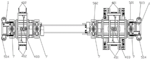
Fig. 1 is the overall structure schematic diagram of the split type self-adaptive floating car carrier of the present invention.
Fig. 2 is a top view of the utility model discloses split type self-adaptation floating car carrier.
Fig. 3 is a top view of the split type adaptive floating car carrier of the present invention.
Fig. 4 is an enlarged detail view of point a in fig. 3.
Fig. 5 is a front view of fig. 1.
Fig. 6 is a schematic view of the structure of the connecting telescopic device.
The reference signs are: the front split type parking device comprises a front split body 1, a chassis frame 101, a rear split body 2, a parking platform 3, a wheel holding device 4, a micro clamping device 401, a speed reducing motor 4011, a lifting block 4012, a crankshaft mechanism 4013, a limiting steel block 4014, a supporting plate 4015, a fixed fork 402, a lateral telescopic device 403, a clamping arm 4031, a screw rod assembly 4032, a motor 4033, a walking mechanism 5, a front driving wheel set 501, a rear driving wheel set 502, a driving motor 503, a limiting wheel set 504, a transmission assembly 505, a connection telescopic device 6, a telescopic guide rod set 601, a servo motor set 602, a telescopic gear 603, a locking unit 604 and a lifting device 7.
Detailed Description
In the following description, numerous specific details are set forth in order to provide a more thorough understanding of the present invention. It will be apparent, however, to one skilled in the art, that the present invention may be practiced without one or more of these specific details. In other instances, well-known features have not been described in order to avoid obscuring the present invention.
As shown in fig. 1 to fig. 6, a split type adaptive floating car carrier and a method for using the same, the carrier is divided into a front split 1 and a rear split 2, and includes: the front split body 1, the rear split body 2, the parking platform 3, the wheel holding device 4, the traveling device, the front split body 2 and the rear split body 2 are connected with the telescopic device 6 and the lifting device 7.
The carrier front split body 1 and the carrier rear split body 2 are fixedly provided with chassis frames 101 which are of an integral welding structure and made of steel materials.
Embrace wheel device 4 fixed mounting and on chassis frame 101 of components of a whole that can function independently 1 and back components of a whole that can function independently 2 before the carrier, include: the device comprises a micro-clamping device 401, a fixed fork 402 and a lateral telescopic device 403, wherein the lateral telescopic device 403 is arranged on a front split body 1 and a rear split body 2 of the carrier, and the micro-clamping device 401 and the fixed fork 402 are arranged at one extending end of the lateral telescopic device 403; the micro-clamping device 401 is arranged on the front split 1 lateral expansion device 403, the fixed fork 402 is arranged on the rear split 2 lateral expansion device 403, and the lateral expansion device 403 comprises: a clamp arm 4031, a motor 4033, and a lead screw assembly, the clamp arm 4031 and the motor 4033 being provided on the chassis frame 101, the lead screw assembly being mounted on the motor 4033 side. The screw rod assemblies are two screw rods which move reversely, the other ends of the screw rods are fixedly connected to the four clamping arms 4031, and the four clamping arms 4031 are provided with slide rails on one side of the clamping arm 4031 close to the chassis frame 101. The clamp arm 4031 can be moved in the reverse direction by the motor 4033.
The traveling mechanism 5 is installed at the bottom of the chassis frame 101, and includes: spacing wheelset 504, driving motor 503, transmission assembly 505 and driving wheelset, spacing wheelset 504 symmetry are installed in chassis frame 101 both sides, and driving motor 503 fixed mounting is on chassis frame 101, and transmission assembly 505 is connected in driving motor 503 one side, and the driving wheelset setting is in chassis frame 101 both sides. The drive wheel sets include a front drive wheel set 501 and a rear drive wheel set 502. The infrared signal receiving device is arranged on the traveling mechanism 5, so that the carrying speed, the advancing direction, the stopping and the starting of the driving wheel set of the traveling mechanism 5 can be remotely controlled.
Connect telescoping device 6 and set up in the opposite side of front and back components of a whole that can function independently 2 and connect telescoping device 6 and connect front and back components of a whole that can function independently 2, include: a telescopic guide rod set 601, a servo motor set 602, a telescopic gear 603 and a locking unit 604. The telescopic guide rod groups 601 are symmetrically installed on the chassis frame 101, one end, arranged at the front split body 1, of the telescopic guide rod group 601 is provided with a limiting block, the telescopic guide rod group 601 is installed on the rear split body 2 through a fixed pin shaft, the servo motor group 602 is arranged on the chassis frame 101 of the front split body 1, the telescopic gear 603 is arranged at one side of the servo motor group 602, and the locking unit 604 is arranged at one side of the telescopic gear 603 and is sleeved on the telescopic guide rod. The telescopic guide rod group 601 is provided with a measuring device, and the telescopic length of the telescopic guide rod can be controlled in time according to the offset distance of the automobile and the speed of the travelling mechanism 5.
The lifting devices 7 are fixedly arranged on the chassis frame 101 and comprise four cam rotary lifters arranged on one side of the driving wheel set. And lifting plates fixedly connected with one end of the cam rotating lifter are respectively and fixedly arranged on two sides of the front and rear split clamping arms. And lifting the automobile parked on the parking platform 3 to enable the automobile to leave the parking platform 3 limited block.
The carrier is parked on the special parking platform 3, the parking platform 3 is provided with a measuring device which can be matched with the carrier for use, and the placement position of the carrier and the telescopic positions of the front and rear split bodies 2 and the lateral telescopic devices 403 can be accurately adjusted according to the weight, the distance and the length of an axle of the vehicle. The parking platform 3 is internally provided with a limit groove and externally provided with a limit block group. The measuring device comprises a wheel base measuring light sensor and a weight sensor which are arranged on the limiting block group.
The driving wheel set comprises a front driving wheel set 501 and a rear driving wheel set 502 which are arranged at two ends of the front split body 1 and the rear split body 2, and an anti-collision baffle is arranged above the limiting wheel set 504. The limit wheel set 504 slides in the limit groove to keep the running direction of the carrier. The transmission assembly 505 includes: a power output device disposed at one side of the driving motor 503, a transmission shaft penetrating the power output device, and gear sets disposed at two sides of the transmission shaft. One section of the transmission shaft lever penetrating through the power output device is provided with a worm, a worm wheel is arranged in the power output device, and the worm wheel is in screwed connection with the worm. The two ends of the transmission shaft rod are provided with main gears, the front driving wheel set 501 is sleeved on the two sides of the chassis frame 101 through the shaft rod, the shaft rod is provided with driven gears, and the main gears are connected with the driven gears in a screwing mode to drive the front driving wheel set 501 to move synchronously.
The micro-gripper devices 401 are four, symmetrically mounted on the gripping arm 4031 of the lateral expansion device 403, and comprise: the support plate 4015 arranged on the clamping arm 4031, the speed reducing motor 4011 fixedly installed on the support plate 4015, the crankshaft mechanism 4013 connected to one end of the speed reducing motor 4011 and the lifting block 4012 connected to one end of the crankshaft mechanism 4013, wherein one side, far away from the support plate 4015, of the lifting block 4012 is a landslide type curved surface, the angle of the lifting block can be adjusted according to the arc surface of an automobile tire, and the acting force on the automobile tire in the lifting process can be reduced. Avoid the tire destruction when the atmospheric pressure is too low. And a limiting steel block 4014 is arranged on one side of the lifting block 4012. Prevent the inclination and the sliding of the automobile caused by the unevenness of the ground in the carrying process. The lifting block is provided with a weight sensor, and whether the front wheel of the automobile deviates or inclines or not can be judged in the driving process.
The locking unit 604 includes: connect soon at the locking tooth piece of expansion gear 603 one side, the briquetting of fixed connection locking tooth piece, fixed connection is at the holding down plate of briquetting one side to and the locking staple bolt of fixed connection in holding down plate one end, the locking staple bolt sets up the outside at flexible guide arm, the locking staple bolt includes left staple bolt and right staple bolt, left side staple bolt and right staple bolt top are provided with the articulated shaft, servo motor group 602 control locking tooth piece up-and-down motion to drive left staple bolt and right staple bolt switching. The telescopic guide rod is telescopic when the left hoop and the right hoop are opened, and the telescopic guide rod is fixed when the left hoop and the right hoop are closed.
The preferred embodiments of the present invention have been described in detail with reference to the accompanying drawings, however, the present invention is not limited to the details of the above embodiments, and the technical concept of the present invention can be modified to perform various equivalent transformations, which all belong to the protection scope of the present invention.
Claims (6)
1. The utility model provides a split type self-adaptation floating car carrier, the carrier divide into preceding components of a whole that can function independently and back components of a whole that can function independently, its characterized in that includes:
the chassis frame is fixedly arranged on the front split body and the rear split body of the carrier;
embrace wheel device, fixed mounting includes on the chassis frame of components of a whole that can function independently and back components of a whole that can function independently before the carrier: the lateral expansion device is arranged on the front split body and the rear split body of the carrier, and the micro-clamping device and the fixed fork are arranged at the extending end of the lateral expansion device; little clamping device sets up in the front on components of a whole that can function independently side direction telescoping device, the stationary fork sets up in the components of a whole that can function independently side direction telescoping device in the back, side direction telescoping device includes: the clamping arm is arranged on the chassis frame, the motor is arranged on the chassis frame, and the screw rod assembly is arranged on one side of the motor;
running gear installs in chassis frame's bottom, includes: the chassis comprises limiting wheel sets symmetrically arranged on two sides of a chassis frame, a driving motor fixedly arranged on the chassis frame, a transmission assembly connected to one side of the driving motor, and driving wheel sets arranged on two sides of the chassis frame;
connect telescoping device, set up in the opposite side of components of a whole that can function independently around the front and back components of a whole that can function independently just connect telescoping device connects, include: the chassis comprises telescopic guide rod groups symmetrically arranged on a chassis frame, a servo motor group arranged on the front split chassis frame, a telescopic gear arranged on one side of the servo motor group, and a locking unit arranged on one side of the telescopic gear and sleeved on a telescopic guide rod; one end of the telescopic guide rod group close to the front split body is provided with a limiting block, and the other end of the telescopic guide rod group is arranged on the rear split body chassis frame through a fixing pin shaft;
the lifting devices are fixedly arranged on the chassis frame and comprise four cam rotary lifters arranged on one side of the driving wheel set, and the four cam rotary lifters are respectively and fixedly arranged on two sides of the front and rear split clamping arms;
the transmission assembly includes: the power output device is arranged on one side of the driving motor, the transmission shaft lever penetrates through the power output device, and the gear sets are arranged on two sides of the transmission shaft lever;
the four clamping arms are symmetrically arranged on the chassis frame which is divided into a front part and a rear part, and a slide rail is arranged at the joint of the clamping arms and the chassis frame.
2. The split adaptive floating car carrier according to claim 1, wherein the carrier is parked on a special parking platform, the parking platform comprises a recessed limiting block group and a limiting groove arranged in the middle of the limiting block group, and a measuring device is arranged on the parking platform; the carrier is parked in the limiting groove, and two groups of grooves are symmetrically formed in the limiting block group; the limiting wheel set slides on two sides of the limiting block set.
3. The split type self-adaptive floating car carrier according to claim 1, wherein the driving wheel sets comprise a front driving wheel set and a rear driving wheel set which are arranged at two ends of a front split body and a rear split body, and an anti-collision baffle is arranged above the limiting wheel set.
4. The split adaptive floating car carrier according to claim 3, wherein a worm is arranged on a section of the transmission shaft rod penetrating through the power output device, a worm wheel is arranged inside the power output device, and the worm wheel is screwed with the worm; the front driving wheel set is sleeved on two sides of the chassis frame through the shaft rod, the shaft rod is provided with a driven gear, and the main gear is in screwed connection with the driven gear to drive the front driving wheel set to move synchronously.
5. The split adaptive floating car carrier of claim 1, wherein said micro-clamping devices are four and symmetrically mounted on lateral telescoping device clamping arms, comprising: the supporting plate of setting on the centre gripping arm, gear motor on the fixed mounting supporting plate connects the bent axle mechanism in gear motor one end to and connect the piece of lifting in bent axle mechanism one end, the piece of lifting is kept away from one side of supporting plate and is the landslide type curved surface, the one side of lifting the piece is provided with spacing steel bloom, the last weighing transducer that is provided with of piece of lifting.
6. The split adaptive floating car carrier of claim 1, wherein said locking unit comprises: connect soon at the locking tooth piece of expansion gear one side, the briquetting of fixed connection locking tooth piece, fixed connection is at the holding down plate of briquetting one side to and the locking staple bolt of fixed connection in holding down plate one end, the locking staple bolt sets up the outside at flexible guide arm, the locking staple bolt includes left staple bolt and right staple bolt, left side staple bolt and right staple bolt top are provided with the articulated shaft, servo motor group drives the switching of the left staple bolt of locking tooth piece up-and-down motion control and right staple bolt.
Priority Applications (1)
| Application Number | Priority Date | Filing Date | Title |
|---|---|---|---|
| CN201920257040.2U CN209958860U (en) | 2019-02-28 | 2019-02-28 | Split type self-adaptation floating car carrier |
Applications Claiming Priority (1)
| Application Number | Priority Date | Filing Date | Title |
|---|---|---|---|
| CN201920257040.2U CN209958860U (en) | 2019-02-28 | 2019-02-28 | Split type self-adaptation floating car carrier |
Publications (1)
| Publication Number | Publication Date |
|---|---|
| CN209958860U true CN209958860U (en) | 2020-01-17 |
Family
ID=69238487
Family Applications (1)
| Application Number | Title | Priority Date | Filing Date |
|---|---|---|---|
| CN201920257040.2U Active CN209958860U (en) | 2019-02-28 | 2019-02-28 | Split type self-adaptation floating car carrier |
Country Status (1)
| Country | Link |
|---|---|
| CN (1) | CN209958860U (en) |
Cited By (1)
| Publication number | Priority date | Publication date | Assignee | Title |
|---|---|---|---|---|
| WO2023128500A1 (en) * | 2021-12-29 | 2023-07-06 | 조민서 | Holder of low-floor parking robot |
-
2019
- 2019-02-28 CN CN201920257040.2U patent/CN209958860U/en active Active
Cited By (1)
| Publication number | Priority date | Publication date | Assignee | Title |
|---|---|---|---|---|
| WO2023128500A1 (en) * | 2021-12-29 | 2023-07-06 | 조민서 | Holder of low-floor parking robot |
Similar Documents
| Publication | Publication Date | Title |
|---|---|---|
| CN209369441U (en) | It is applicable in the all-electric automatic parking robot of different wheelbases and wheelspan | |
| CN102900256B (en) | Intelligent automobile lengthways handling device | |
| CN106672853B (en) | A kind of full-bearing type car power assembly assembly method and tooling | |
| CN112282459B (en) | AGV intelligent transfer robot for stereo parking garage and working method thereof | |
| CN110986697A (en) | Multifunctional rocket cabin docking vehicle | |
| CN112110384A (en) | Auxiliary stacking robot | |
| CN110979722A (en) | A trailer that is used for automatic walking of aircraft engine to dock | |
| CN209958860U (en) | Split type self-adaptation floating car carrier | |
| CN110789280A (en) | Conversion method for tire walking and rail walking of tunnel vehicle | |
| CN208073067U (en) | A kind of car carrying mechanism | |
| CN109958309B (en) | Split type self-adaptive floating car carrier and working method thereof | |
| CN219316550U (en) | Horizontal carrier for vehicle | |
| CN210563646U (en) | Grab car lifting device | |
| CN108222602A (en) | A kind of automobile carrying device | |
| CN109403683B (en) | Clamp holding/clamping device for intelligent parking robot | |
| CN208164661U (en) | A kind of three axis displacement automotive wheel tightening device | |
| CN215706778U (en) | AGV dolly is used in parking area vehicle transfer | |
| CN206128771U (en) | Side direction horizontal type centre gripping moves car robot | |
| CN110294432B (en) | Double-column lifting gripper structure for assisting automatic parking of automobile and operation method | |
| CN105621038A (en) | Mobile feeding mechanism for automobile roof | |
| CN210655963U (en) | Double-column lifting gripper structure for assisting automatic parking of automobile | |
| CN209369444U (en) | Telescopic all-electric automatic parking robot inside and outside faced chamber | |
| CN210310102U (en) | Automobile carrying equipment | |
| CN112761396A (en) | Four-way walking parking carrier | |
| CN107200081B (en) | A kind of vehicle frame support member of trailer assembly system |
Legal Events
| Date | Code | Title | Description |
|---|---|---|---|
| GR01 | Patent grant | ||
| GR01 | Patent grant |