CN110977297A - Welding positioning device for turbine impeller and finished rotor shaft of turbocharger - Google Patents
Welding positioning device for turbine impeller and finished rotor shaft of turbocharger Download PDFInfo
- Publication number
- CN110977297A CN110977297A CN201911327728.4A CN201911327728A CN110977297A CN 110977297 A CN110977297 A CN 110977297A CN 201911327728 A CN201911327728 A CN 201911327728A CN 110977297 A CN110977297 A CN 110977297A
- Authority
- CN
- China
- Prior art keywords
- shaft sleeve
- rotor shaft
- welding
- sleeve
- finished rotor
- Prior art date
- Legal status (The legal status is an assumption and is not a legal conclusion. Google has not performed a legal analysis and makes no representation as to the accuracy of the status listed.)
- Pending
Links
Images


Classifications
-
- B—PERFORMING OPERATIONS; TRANSPORTING
- B23—MACHINE TOOLS; METAL-WORKING NOT OTHERWISE PROVIDED FOR
- B23K—SOLDERING OR UNSOLDERING; WELDING; CLADDING OR PLATING BY SOLDERING OR WELDING; CUTTING BY APPLYING HEAT LOCALLY, e.g. FLAME CUTTING; WORKING BY LASER BEAM
- B23K37/00—Auxiliary devices or processes, not specially adapted to a procedure covered by only one of the preceding main groups
- B23K37/04—Auxiliary devices or processes, not specially adapted to a procedure covered by only one of the preceding main groups for holding or positioning work
- B23K37/0426—Fixtures for other work
- B23K37/0435—Clamps
- B23K37/0443—Jigs
-
- B—PERFORMING OPERATIONS; TRANSPORTING
- B23—MACHINE TOOLS; METAL-WORKING NOT OTHERWISE PROVIDED FOR
- B23K—SOLDERING OR UNSOLDERING; WELDING; CLADDING OR PLATING BY SOLDERING OR WELDING; CUTTING BY APPLYING HEAT LOCALLY, e.g. FLAME CUTTING; WORKING BY LASER BEAM
- B23K37/00—Auxiliary devices or processes, not specially adapted to a procedure covered by only one of the preceding main groups
- B23K37/04—Auxiliary devices or processes, not specially adapted to a procedure covered by only one of the preceding main groups for holding or positioning work
- B23K37/053—Auxiliary devices or processes, not specially adapted to a procedure covered by only one of the preceding main groups for holding or positioning work aligning cylindrical work; Clamping devices therefor
Abstract
The invention discloses a welding positioning device for a turbine impeller and a finished product rotor shaft of a turbocharger, which comprises a positioning clamp body, wherein the upper part of the positioning clamp body is provided with a welding operation channel which is transversely distributed; the upper side and the lower side of the channel are respectively provided with an anti-falling auxiliary disc accommodating groove and a shaft sleeve mounting cavity; the anti-falling auxiliary disc is placed in the anti-falling auxiliary disc accommodating groove; a turbine impeller accommodating groove is formed in the center of the anti-falling auxiliary disc; a turbine impeller is arranged in the turbine impeller accommodating groove; a main shaft sleeve is inserted into the shaft sleeve mounting cavity; a reducing shaft sleeve accommodating cavity is formed in the main shaft sleeve; the reducing shaft sleeve is inserted into the upper part of the reducing shaft sleeve accommodating cavity; the top of the reducing shaft sleeve is fixedly connected with the top of the main shaft sleeve; a finished rotor shaft is vertically inserted into a finished rotor shaft accommodating cavity in the reducing shaft sleeve in a penetrating manner; the turbine wheel is connected with the finished rotor shaft. The invention can quickly and reliably position and restrain the turbine impeller and the finished product rotor shaft, is convenient for an external welding device to carry out welding operation, and ensures the production quality of the finished product turbine rotating shaft.
Description
Technical Field
The invention relates to the technical field of machinery, in particular to a welding and positioning device for a turbine impeller and a finished product rotor shaft of a turbocharger.
Background
Turbochargers are important components for increasing engine power, reducing fuel consumption, and improving emissions. Under the strict environmental protection requirement of the national execution state six-emission standard, the exhaust gas turbocharging becomes an engine standard component, and how to improve the manufacturing capability and the processing efficiency of the turbocharger becomes a consistent target of various manufacturers.
The turbine rotating shaft is a core part of the turbocharger, is an assembly formed by welding a turbine impeller (cast by nickel-based high-temperature alloy K418) and a rotor shaft (42CrMo bar), has the working rotating speed on the automobile turbocharger up to more than 15 ten thousand revolutions per minute, is severe in working environment, has good and bad processing quality, and directly influences the performance and the reliability of the turbocharger.
For a turbine rotating shaft, the existing processing technology is as follows: after the turbine impeller and the blank rotor shaft are welded, rough machining and finish machining are carried out on the shaft rod part, the machining process is long in route, the production period is long, factors influencing the product quality in the machining process are many, and the quality of the finished turbine rotating shaft is easy to cause instability. To avoid these adverse effects, only the improved process is to innovatively employ the direct welding of the turbine wheel and the finished rotor shaft by finishing the turbine wheel and the rotor shaft to size and then welding.
However, at present, there is no technology that can quickly and reliably position and restrain the turbine impeller and the finished rotor shaft, so as to facilitate the welding operation of an external welding device and ensure the stable quality of the finally produced finished turbine rotating shaft.
Disclosure of Invention
The invention aims to provide a welding and positioning device for a turbine impeller and a finished product rotor shaft of a turbocharger, aiming at the technical defects in the prior art.
Therefore, the invention provides a welding and positioning device for a turbine impeller and a finished product rotor shaft of a turbocharger, which comprises a positioning clamp body;
the upper part of the positioning clamp body is provided with welding operation channels which transversely penetrate through and are distributed;
an anti-falling auxiliary disc accommodating groove is formed above the welding operation channel;
an anti-falling auxiliary disc is arranged in the anti-falling auxiliary disc accommodating groove;
a turbine impeller accommodating groove with an upper opening and a lower opening is formed in the central position of the anti-falling auxiliary disc;
a turbine impeller is vertically arranged in the turbine impeller accommodating groove;
a shaft sleeve mounting cavity which is vertically distributed is arranged below the welding operation channel;
the spindle sleeve is arranged in the shaft sleeve mounting cavity and vertically inserted with the spindle sleeve;
a reducing shaft sleeve accommodating cavity which is vertically distributed is arranged in the main shaft sleeve;
the reducing shaft sleeve is inserted into the upper part of the reducing shaft sleeve accommodating cavity;
the top of the reducing shaft sleeve is fixedly connected with the top of the main shaft sleeve;
finished rotor shaft accommodating cavities which are vertically distributed are formed in the variable-diameter shaft sleeve;
the finished rotor shaft accommodating cavity is vertically inserted with a finished rotor shaft in a penetrating way;
the top of the finished rotor shaft protrudes upwards from the finished rotor shaft accommodating cavity;
the turbine impeller is positioned right above the finished rotor shaft;
the turbine wheel is connected with the finished rotor shaft.
Wherein, the top center position of the finished rotor shaft is pre-processed with a connecting shaft head;
an inner hole is pre-processed at the bottom of the turbine impeller at a position corresponding to the connecting shaft head;
and the connecting shaft head at the top of the finished rotor shaft is inserted into an inner hole at the bottom of the wheel blade.
Wherein, the finished product rotor shaft holds the cavity, and turbine wheel holding tank is located same central axis.
Two first radial bearings are arranged between the outer wall of the upper part of the main shaft sleeve and the inner wall of the shaft sleeve mounting cavity;
a second radial bearing is arranged between the outer wall of the middle lower part of the main shaft sleeve and the inner wall of the shaft sleeve mounting cavity;
the first radial bearing and the second radial bearing are sleeved on the outer wall of the main shaft sleeve;
the outer wall of the shaft sleeve is also sleeved with an adjusting spacer sleeve which is distributed annularly;
the position of the spacer sleeve between the first radial bearing and the second radial bearing is adjusted.
The anti-falling auxiliary disc accommodating groove is communicated with the middle part of the upper side of the welding operation channel;
the shaft sleeve is provided with a cavity which is communicated with the middle part of the lower side of the welding operation channel.
The size of a first horizontal supporting platform arranged at the top of the spindle sleeve is larger than the size of a top opening of the shaft sleeve mounting cavity;
the size of the second horizontal supporting platform arranged at the top of the reducing shaft sleeve is larger than the size of the top opening of the accommodating cavity of the reducing shaft sleeve.
Wherein, a tilting prevention auxiliary disc is covered above a first horizontal supporting table arranged at the top of the main shaft sleeve and a second horizontal supporting table arranged at the top of the reducing shaft sleeve;
the size of the anti-falling auxiliary disc is larger than that of the second horizontal supporting table arranged on the top of the first horizontal supporting table and the top of the reducing shaft sleeve.
The anti-falling auxiliary disc is positioned below a preset welding position between the turbine impeller and the finished product rotor shaft;
the bottom of the anti-falling auxiliary disc is provided with bosses distributed in a surrounding mode, and the bosses cover the outer wall of the top of the second horizontal supporting table.
Wherein, the outer wall of the lower part of the main shaft sleeve is sleeved with an end cover;
the top of the end cover is contacted with the bottom of the second radial bearing;
the peripheral edge of the end cover is fixedly connected with the bottom of the positioning clamp body through a plurality of screws distributed at intervals.
The outer wall of the lower part of the main shaft sleeve is in threaded connection with a locking nut at a position below the end cover;
a pressing pad is annularly distributed between the locking nut and the end cover;
the outer wall around the end of the lower part of the main shaft sleeve is provided with a plurality of transmission pins at equal intervals.
Compared with the prior art, the technical scheme provided by the invention has the advantages that the welding positioning device for the turbine impeller and the finished product rotor shaft of the turbocharger can quickly and reliably position and restrain the turbine impeller and the finished product rotor shaft, so that an external welding device can conveniently perform welding operation, the quality of the finally produced finished product turbine rotating shaft is ensured to be stable, and the welding positioning device has great production practice significance.
Drawings
FIG. 1 is a cross-sectional view of a turbocharger turbine wheel and finished rotor shaft weld fixture provided in accordance with the present invention;
FIG. 2 is a top view of a turbocharger turbine wheel and finished rotor shaft weld fixture provided in accordance with the present invention;
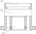
FIG. 3 is a front view of a positioning fixture body in the welding and positioning device for a turbocharger turbine wheel and a finished rotor shaft provided by the invention;
FIG. 4 is a cross-sectional view of a positioning fixture body in the welding and positioning device for a turbocharger turbine wheel and a finished rotor shaft provided by the invention;
FIG. 5 is a front view of a spindle cover of a welding and positioning device for a turbine wheel and a finished rotor shaft of a turbocharger according to the present invention;
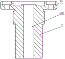
FIG. 6 is a cross-sectional view of a variable diameter shaft sleeve in the welding and positioning device for a turbine impeller and a finished rotor shaft of a turbocharger provided by the invention;
FIG. 7 is an enlarged cross-sectional view of a splash shield in the welding fixture for a turbocharger turbine wheel and a finished rotor shaft according to the present invention;
in the figure: 1. the positioning fixture comprises a positioning fixture body, a main shaft sleeve, a reducing shaft sleeve, a first radial bearing, a second radial bearing, a main shaft sleeve, a reducing shaft sleeve, a main;
6. the anti-falling auxiliary disc 7, the adjusting spacer sleeve 8, the end cover 9, the compression pad 10 and the locking nut; 11. a drive pin;
100. a turbine wheel, 200, a finished rotor shaft;
101. the anti-falling auxiliary disc accommodating groove 102, the welding operation channel 103 and the shaft sleeve mounting cavity are formed in the shaft sleeve;
201. a first horizontal support platform 202 and a reducing shaft sleeve accommodating cavity;
301. a second horizontal support platform 302, a finished rotor shaft receiving cavity;
501. boss 601, turbine wheel holding tank.
Detailed Description
In order that those skilled in the art will better understand the technical solution of the present invention, the following detailed description of the present invention is provided in conjunction with the accompanying drawings and embodiments.
Referring to fig. 1 to 7, the invention provides a welding and positioning device for a turbine impeller and a finished rotor shaft of a turbocharger, in particular to a high-precision positioning technology and a quick clamping technology in welding the turbine impeller and the finished rotor shaft in the production of the turbocharger, and the device comprises a positioning clamp body 1;
the upper part of the positioning clamp body 1 is provided with a welding operation channel 102 (which is a hollow cavity) transversely distributed through;
an anti-falling auxiliary disc accommodating groove 101 is formed above the welding operation channel 12;
an anti-falling auxiliary disc 6 is placed in the anti-falling auxiliary disc accommodating groove 101;
a turbine impeller accommodating groove 601 with an upper opening and a lower opening is formed in the central position of the anti-falling auxiliary disc 6;
the turbine impeller 100 is vertically arranged in the turbine impeller accommodating groove 601;
below the welding operation channel 12, there are vertically distributed shaft sleeve mounting cavities 103;
a spindle sleeve 2 is inserted into the spindle sleeve mounting cavity 103 from top to bottom;
the main shaft sleeve 2 is internally provided with a reducing shaft sleeve accommodating cavity 202 which is vertically distributed;
the reducing shaft sleeve 3 is inserted into the upper part of the reducing shaft sleeve accommodating cavity 202;
the top of the reducing shaft sleeve 3 is fixedly connected with the top of the main shaft sleeve 2 (specifically through a plurality of screws distributed at intervals);
finished rotor shaft accommodating cavities 302 which are vertically distributed are formed in the reducing shaft sleeve 3;
a finished rotor shaft receiving cavity 302 into which the finished rotor shaft 200 is vertically inserted;
the top of finished rotor shaft 200 protrudes upwardly from finished rotor shaft receiving cavity 302;
the turbine wheel 100 is located directly above the finished rotor shaft 200;
In the invention, in the concrete implementation, a connecting shaft head is pre-processed at the top center position of the finished rotor shaft 200;
an inner hole is pre-processed at the bottom of the turbine impeller 100 at a position corresponding to the connecting shaft head;
the connecting stub shaft at the top of the finished rotor shaft 200 is inserted into the internal bore at the bottom of the bucket wheel 100.
In the present invention, the finished rotor shaft receiving cavity 302, and the turbine wheel receiving slot 601, are located on the same central axis for a specific implementation.
In the present invention, in a specific implementation, two first centering bearings 41 are provided between the upper outer wall of the main shaft sleeve 2 and the inner wall of the sleeve mounting cavity 103;
a second radial bearing 42 is arranged between the outer wall of the middle lower part of the main shaft sleeve 2 and the inner wall of the sleeve mounting cavity 103;
the first axial bearing 41 and the second axial bearing 42 are sleeved on the outer wall of the main shaft sleeve 2;
the outer wall of the shaft sleeve 2 is also sleeved with an adjusting spacer sleeve 7 which is distributed annularly;
the spacer 7 is adjusted to a position between the first and second radial bearings 41 and 42.
In the present invention, in a concrete implementation, the falling prevention auxiliary disk accommodating groove 101 is communicated with the upper middle part of the welding operation channel 12;
the bushing installation cavity 103 is communicated with the lower middle part of the welding operation passage 12.
In the present invention, in a concrete implementation, the size of the first horizontal support platform 201 on the top of the spindle sleeve 2 is larger than the size of the top opening of the sleeve mounting cavity 103.
In the present invention, in a specific implementation, the size of the second horizontal support platform 301 on the top of the reducer sleeve 3 is larger than the size of the top opening of the reducer sleeve accommodating cavity 202.
In the invention, in the concrete implementation, an anti-falling auxiliary disc 5 is covered above a first horizontal supporting table 201 arranged at the top of a main shaft sleeve 2 and a second horizontal supporting table 301 arranged at the top of a reducing shaft sleeve 3;
the size of the anti-falling auxiliary disc 5 is larger than the size of the second horizontal support platform 301 arranged at the tops of the first horizontal support platform 201 and the reducing shaft sleeve 3, so that spatters caused by welding can be prevented, and the second horizontal support platform 301 arranged at the tops of the first horizontal support platform 201 and the reducing shaft sleeve 3 is damaged.
In particular, the anti-fall auxiliary disk 5 is located below a preset welding position between the turbine impeller 100 and the finished rotor shaft 200.
In concrete implementation, the bottom of the falling prevention auxiliary disc 5 is provided with bosses 501 distributed in a surrounding manner, and the bosses are covered on the outer wall of the top of the second horizontal support platform 301.
In the invention, in the concrete implementation, the outer wall of the lower part of the main shaft sleeve 2 is sleeved with an end cover 8;
the top of the end cap 8, in contact with the bottom of the second axial bearing 42;
the peripheral edge of the end cover 8 is fixedly connected with the bottom of the positioning clamp body 1 through a plurality of screws distributed at intervals.
In particular, the outer wall of the lower part of the main shaft sleeve 2 is in threaded connection with a locking nut 10 at a position below the end cover 8;
between the locking nut 8 and the end cap 8, there are annularly distributed pressure pads 9.
In the invention, in the concrete implementation, a plurality of transmission pins 11 are distributed on the peripheral outer wall of the lower end of the main shaft sleeve 2 at equal intervals;
and a driving pin 11 for fixedly connecting a driving shaft (specifically, a rotating shaft of a driving motor provided therein) of an externally located vacuum electron beam welding machine (specifically, TW04 vacuum electron beam welding machine) with a lower end of the sleeve 2.
It should be noted that, based on the above technical solutions, for the present invention, the self-centering property of the first radial bearing and the second radial bearing is utilized, and the offset of the parts before welding is constrained in a manner of positioning the shaft rod of the parts, which is not limited by the shape of the blades of the turbine impeller and the size of the hub, so as to avoid the influence of inconsistent casting quality (machining precision) of the blank of the turbine impeller, and the parts can be quickly mounted and clamped;
the invention adopts the axial and radial positioning constraint of the workpiece, only the rotation dimension is reserved, the pressure applied to the workpiece during welding is ensured to be kept stable in the welding process, and the influence caused by overlarge perpendicularity of the turbine impeller wheel back relative to the shaft lever after the workpiece is welded due to welding stress is eliminated to the maximum extent, so that the welding of the turbine impeller and the finished product rotor shaft can be realized; when the design is carried out, the modularized design concept is integrated into the rush horse, the adaptive reducing shaft sleeve is adopted, the welding of finished rotor shafts with various shaft diameters can be met, and the rapid model change can be realized in batch production.
According to the invention, the adaptive reducing shaft sleeve is designed according to the shaft diameter of the finished rotor shaft so as to be used for positioning the finished rotor shaft, the turbine impeller is connected with the finished rotor shaft through a preprocessed inner hole to realize self-centering, and the pneumatic tail top of the turbine impeller is compressed by using external welding equipment (namely a vacuum electron beam welding machine). And then the lower end of the main shaft sleeve is fixedly connected with a rotating shaft of a motor in the vacuum electron beam welding machine through a transmission pin so as to rotate, and finally, the continuous welding (along with the rotation, the connection welding is realized) of the welding position between the turbine impeller of the turbine rotating shaft and the finished product rotor shaft is realized.
The invention relates to a positioning device for a turbocharger turbine impeller and a finished product rotor shaft during electron beam welding, which is researched for improving the existing process method, improving the production efficiency and reducing the production cost.
In order to more clearly understand the technical scheme of the invention, the operation process of the invention for mounting and matching to perform welding is described below.
Firstly, tool installation: the welding positioning device is arranged in a tray of the vacuum electron beam welding machine through the positioning spigot, is in place at one time and only needs to be taken down when in maintenance. Before welding, selecting a corresponding matched reducing shaft sleeve 3 according to the diameter size of a finished rotor shaft 200, cleaning the contact surface of the reducing shaft sleeve 3, and naturally and smoothly installing the reducing shaft sleeve 3 into the main shaft sleeve 2; in addition, an appropriate anti-falling auxiliary disc 6 can be selected according to the maximum outer diameter of the turbine impeller 100, and the replacement is very simple and convenient.
And secondly, matching the processes of starting welding operation. The method comprises the following specific steps:
firstly, inserting a finished rotor shaft 200 into a reducing shaft sleeve 3 of the tool;
then, the turbine impeller 100 is placed on the rotor shaft (the turbine impeller is provided with an inner hole, and the end part of the rotor shaft is provided with a small shaft head which is correspondingly arranged), so that the turbine impeller 100 can freely rotate on the finished rotor shaft 200 without a hairpin state;
then, the device is placed on the top of a cylinder at the bottom of a vacuum electron beam welding machine, a welding switch of the vacuum electron beam welding machine is started, the cylinder at the bottom of the vacuum electron beam welding machine is jacked upwards, the device is sent into a vacuum welding chamber, the vacuum welding chamber is sealed at the same time, and the top tail jack (the pneumatic tail jack arranged on the vacuum electron beam welding machine) at the top of the vacuum electron beam welding machine moves downwards to press the turbine impeller 100.
Then, the lower end of the main shaft sleeve 2 is fixedly connected with a transmission shaft of a vacuum electron beam welding machine (specifically, a TW04 vacuum electron beam welding machine) through a transmission pin 11, the main shaft sleeve 2 rotates with parts to be welded (including a turbine impeller 100 and a finished rotor shaft 200 which are placed together) under the driving of the transmission shaft, after the vacuum degree of a vacuum welding chamber reaches a preset requirement, the vacuum electron beam welding machine sends out an electron beam for welding, and the joint of the turbine impeller 100 and the finished rotor shaft 200 is welded through a welding operation channel 102 on a positioning fixture body.
In particular, the TW04 vacuum electron beam welding machine is an existing vacuum electron beam welding machine, for example, a TW04 vacuum electron beam welding machine produced by the british CVE company can be used, a welding device and a welding positioning device of the welding machine are arranged in double stations, a rotary driving device is installed at the bottom of a working platform to drive the double stations to rotate by 180 degrees, an inlet and an outlet are formed in the bottom of a vacuum chamber, the welding positioning device can vertically lift under the driving of an air cylinder, and when the welding positioning device lifts, the welding positioning device is sealed with the bottom of the vacuum chamber to perform welding processing.
Compared with the prior art, the welding and positioning device for the turbine impeller and the finished product rotor shaft of the turbocharger provided by the invention has the following beneficial effects:
1. the welding positioning device for the turbine impeller and the finished product rotor shaft of the turbocharger provided by the invention solves the welding positioning problem of the turbine impeller and the finished product rotor shaft, the perpendicularity of the back of the turbine impeller and the rod part after welding is less than 0.08mm, and the jumping of the welding part is less than 0.05mm, so that the design requirement can be completely met. The adjustment and replacement of the whole tool are simple and convenient to operate, professional training is not needed, rapid type replacement can be realized, the production efficiency is greatly improved, the positioning in the welding process is stable and reliable, and the welding quality of the final finished turbine rotating shaft is effectively guaranteed.
2. The invention directly adopts the shaft diameter of the finished rotor shaft for positioning welding, ensures the geometric tolerance requirement of the welded parts, and can meet the design requirement of directly welding the turbine impeller and the finished rotor shaft; meanwhile, compared with the original production efficiency of reprocessing after welding, the production efficiency is greatly improved, and the production can be quickly switched to respond to the market order requirement.
In summary, compared with the prior art, the welding and positioning device for the turbine impeller and the finished rotor shaft of the turbocharger provided by the invention can quickly and reliably position and restrain the turbine impeller and the finished rotor shaft, so that an external welding device can conveniently perform welding operation, the quality stability of the finally produced finished turbine rotating shaft is ensured, and the welding and positioning device has great production practice significance.
The foregoing is only a preferred embodiment of the present invention, and it should be noted that, for those skilled in the art, various modifications and decorations can be made without departing from the principle of the present invention, and these modifications and decorations should also be regarded as the protection scope of the present invention.
Claims (10)
1. A welding and positioning device for a turbine impeller and a finished product rotor shaft of a turbocharger is characterized by comprising a positioning clamp body (1);
the upper part of the positioning clamp body (1) is provided with a welding operation channel (102) which transversely penetrates through and is distributed;
an anti-falling auxiliary disc accommodating groove (101) is formed above the welding operation channel (12);
an anti-falling auxiliary disc (6) is arranged in the anti-falling auxiliary disc accommodating groove (101);
a turbine impeller accommodating groove (601) with an upper opening and a lower opening is formed in the central position of the anti-falling auxiliary disc (6);
a turbine impeller (100) is vertically arranged in the turbine impeller accommodating groove (601);
a shaft sleeve mounting cavity (103) which is vertically distributed is arranged below the welding operation channel (12);
a spindle sleeve (2) is inserted into the shaft sleeve mounting cavity (103) from top to bottom;
the spindle sleeve (2) is internally provided with a reducing shaft sleeve accommodating cavity (202) which is vertically distributed;
the reducing shaft sleeve (3) is inserted into the upper part of the reducing shaft sleeve accommodating cavity (202);
the top of the reducing shaft sleeve (3) is fixedly connected with the top of the main shaft sleeve (2);
finished rotor shaft accommodating cavities (302) which are vertically distributed are arranged in the reducing shaft sleeve (3);
a finished rotor shaft receiving cavity (302) into which the finished rotor shaft (200) is vertically inserted;
the top of the finished rotor shaft (200) protrudes upwards from the finished rotor shaft accommodating cavity (302);
the turbine wheel (100) is positioned right above the finished rotor shaft (200);
the turbine wheel (100) is connected to a finished rotor shaft (200).
2. The welding and positioning device for the turbine impeller and the finished rotor shaft of the turbocharger as claimed in claim 1, wherein a connecting shaft head is pre-processed at the top center position of the finished rotor shaft (200);
an inner hole is pre-processed at the bottom of the turbine impeller (100) at a position corresponding to the connecting shaft head;
the connecting shaft head at the top of the finished rotor shaft (200) is inserted into an inner hole at the bottom of the vane wheel (100).
3. The apparatus for weld-locating a turbocharger turbine wheel to a finished rotor shaft as claimed in claim 1, wherein the finished rotor shaft receiving cavity (302), and the turbine wheel receiving groove (601), are located on the same central axis.
4. The welding and positioning device for the turbine impeller and the finished rotor shaft of the turbocharger as in claim 1, wherein two first radial bearings (41) are arranged between the upper outer wall of the main shaft sleeve (2) and the inner wall of the shaft sleeve mounting cavity (103);
a second radial bearing (42) is arranged between the outer wall of the middle lower part of the main shaft sleeve (2) and the inner wall of the shaft sleeve mounting cavity (103);
the first radial bearing (41) and the second radial bearing (42) are sleeved on the outer wall of the spindle sleeve (2);
the outer wall of the shaft sleeve (2) is also sleeved with an adjusting spacer sleeve (7) which is distributed annularly;
the position of the spacing sleeve (7) is adjusted between the first radial bearing (41) and the second radial bearing (42).
5. The welding fixture of turbocharger turbine wheel and finished rotor shaft according to claim 1, characterized in that the fall prevention auxiliary disc accommodating groove (101) is communicated with the upper middle part of the welding operation channel (12);
the shaft sleeve mounting cavity (103) is communicated with the lower middle part of the welding operation channel (12).
6. The welding fixture of turbocharger turbine wheel and finished rotor shaft as claimed in claim 1, characterized in that the spindle sleeve (2) has a top portion with a first horizontal support platform (201) of a size larger than the top opening of the sleeve mounting cavity (103);
the size of a second horizontal support platform (301) arranged at the top of the reducing shaft sleeve (3) is larger than the size of the top opening of the reducing shaft sleeve accommodating cavity (202).
7. The welding and positioning device for the turbine impeller and the finished rotor shaft of the turbocharger as claimed in claim 6, wherein the anti-falling auxiliary disc (5) is covered above a first horizontal supporting table (201) arranged at the top of the main shaft sleeve (2) and a second horizontal supporting table (301) arranged at the top of the reducer shaft sleeve (3);
the size of the anti-falling auxiliary disc (5) is larger than the size of a second horizontal support table (301) arranged at the tops of the first horizontal support table (201) and the reducing shaft sleeve (3).
8. The welding fixture of a turbocharger turbine wheel and a finished rotor shaft as set forth in claim 7, characterized in that the anti-backup auxiliary disk (5) is located below a preset welding position between the turbine wheel (100) and the finished rotor shaft (200);
the bottom of the anti-falling auxiliary disc (5) is provided with bosses (501) distributed around, and the bosses are covered on the outer wall of the top of the second horizontal supporting table (301).
9. The welding and positioning device for the turbine impeller and the finished rotor shaft of the turbocharger as claimed in claim 1, wherein an end cover (8) is sleeved on the outer wall of the lower part of the main shaft sleeve (2);
the top of the end cover (8) is contacted with the bottom of the second radial bearing (42);
the peripheral edge of the end cover (8) is fixedly connected with the bottom of the positioning clamp body (1) through a plurality of screws distributed at intervals.
10. The welding and positioning device for the turbine impeller and the finished rotor shaft of the turbocharger as claimed in claim 1, characterized in that the lower outer wall of the main shaft sleeve (2) is further screwed with a lock nut (10) at a position below the end cover (8);
a pressing pad (9) is annularly distributed between the locking nut (8) and the end cover (8);
the peripheral outer wall of the lower end of the main shaft sleeve (2) is provided with a plurality of transmission pins (11) at equal intervals.
Priority Applications (1)
| Application Number | Priority Date | Filing Date | Title |
|---|---|---|---|
| CN201911327728.4A CN110977297A (en) | 2019-12-20 | 2019-12-20 | Welding positioning device for turbine impeller and finished rotor shaft of turbocharger |
Applications Claiming Priority (1)
| Application Number | Priority Date | Filing Date | Title |
|---|---|---|---|
| CN201911327728.4A CN110977297A (en) | 2019-12-20 | 2019-12-20 | Welding positioning device for turbine impeller and finished rotor shaft of turbocharger |
Publications (1)
| Publication Number | Publication Date |
|---|---|
| CN110977297A true CN110977297A (en) | 2020-04-10 |
Family
ID=70073641
Family Applications (1)
| Application Number | Title | Priority Date | Filing Date |
|---|---|---|---|
| CN201911327728.4A Pending CN110977297A (en) | 2019-12-20 | 2019-12-20 | Welding positioning device for turbine impeller and finished rotor shaft of turbocharger |
Country Status (1)
| Country | Link |
|---|---|
| CN (1) | CN110977297A (en) |
Cited By (3)
| Publication number | Priority date | Publication date | Assignee | Title |
|---|---|---|---|---|
| CN112615497A (en) * | 2021-01-08 | 2021-04-06 | 中国船舶重工集团公司第七0七研究所 | Tool applied to motor rotor bonding and positioning and use method |
| CN113458575A (en) * | 2021-07-22 | 2021-10-01 | 詹伟 | Vacuum electron beam welding turbine shaft |
| CN113612409A (en) * | 2021-07-13 | 2021-11-05 | 湖南科太电气有限公司 | High-voltage soft starter shaft sleeve device |
-
2019
- 2019-12-20 CN CN201911327728.4A patent/CN110977297A/en active Pending
Cited By (4)
| Publication number | Priority date | Publication date | Assignee | Title |
|---|---|---|---|---|
| CN112615497A (en) * | 2021-01-08 | 2021-04-06 | 中国船舶重工集团公司第七0七研究所 | Tool applied to motor rotor bonding and positioning and use method |
| CN112615497B (en) * | 2021-01-08 | 2023-01-17 | 中国船舶重工集团公司第七0七研究所 | Tool applied to motor rotor bonding and positioning and use method |
| CN113612409A (en) * | 2021-07-13 | 2021-11-05 | 湖南科太电气有限公司 | High-voltage soft starter shaft sleeve device |
| CN113458575A (en) * | 2021-07-22 | 2021-10-01 | 詹伟 | Vacuum electron beam welding turbine shaft |
Similar Documents
| Publication | Publication Date | Title |
|---|---|---|
| CN110977297A (en) | Welding positioning device for turbine impeller and finished rotor shaft of turbocharger | |
| CN207087406U (en) | A kind of thin-walled cone bay section housing Quick self-centering positioner | |
| US6830240B2 (en) | Methods and apparatus for securing components for manufacture | |
| US20070119040A1 (en) | Methods and apparatus for securing components for manufacture | |
| CN111843562A (en) | Air supporting gear shaping anchor clamps and gear shaping machine | |
| CN211991551U (en) | Welding positioning device for turbine impeller and finished rotor shaft of turbocharger | |
| CN110539170A (en) | Machining method of high-precision hollow sleeve | |
| CN201211581Y (en) | Bevel wheel shaft double locating supporting gear milling clamper | |
| CN102332788B (en) | Motor production technology | |
| CN211707930U (en) | Pump impeller indexing positioning device | |
| CN111451651B (en) | Engine leather cup cutting clamp and cutting method | |
| CN215356712U (en) | Horizontal electric turntable tool for laser welding | |
| CN209802221U (en) | Quick correcting unit | |
| CN209665111U (en) | A kind of grinding fixture of the long Model For The Bush-axle Type Parts of non-full circle | |
| CN208033667U (en) | A kind of spherical surface processing tool based on lathe in machining V-type semicircle valve ball | |
| CN216939361U (en) | Impeller type casting part correcting mechanism | |
| CN219113679U (en) | Turbocharger blade processing device | |
| CN214559085U (en) | Motorcycle cylinder body milling fixture | |
| CN217032254U (en) | Powder metallurgy air inlet cover plate position degree detection tool | |
| CN220815915U (en) | Transmission block for simulating engine to drive oil pump with rotor shaft | |
| CN216176743U (en) | End cover clamping and fixing device for construction machinery | |
| CN115946067B (en) | Press mounting jig | |
| CN219900627U (en) | Empty cover stator mouth ring seat resistance welding frock | |
| CN215919443U (en) | Laser welding tool equipment for shell and fixing feet | |
| CN217666476U (en) | Overcome centrifugal force's stator spindle nose turning tool equipment |
Legal Events
| Date | Code | Title | Description |
|---|---|---|---|
| PB01 | Publication | ||
| PB01 | Publication | ||
| SE01 | Entry into force of request for substantive examination | ||
| SE01 | Entry into force of request for substantive examination |