CN110977115A - Automatic MIG pulse welding equipment for electric heating wall-mounted water casing pipe - Google Patents
Automatic MIG pulse welding equipment for electric heating wall-mounted water casing pipe Download PDFInfo
- Publication number
- CN110977115A CN110977115A CN201911395192.XA CN201911395192A CN110977115A CN 110977115 A CN110977115 A CN 110977115A CN 201911395192 A CN201911395192 A CN 201911395192A CN 110977115 A CN110977115 A CN 110977115A
- Authority
- CN
- China
- Prior art keywords
- welding
- mig
- cylinder
- wall
- automatic
- Prior art date
- Legal status (The legal status is an assumption and is not a legal conclusion. Google has not performed a legal analysis and makes no representation as to the accuracy of the status listed.)
- Granted
Links
Images


Classifications
-
- B—PERFORMING OPERATIONS; TRANSPORTING
- B23—MACHINE TOOLS; METAL-WORKING NOT OTHERWISE PROVIDED FOR
- B23K—SOLDERING OR UNSOLDERING; WELDING; CLADDING OR PLATING BY SOLDERING OR WELDING; CUTTING BY APPLYING HEAT LOCALLY, e.g. FLAME CUTTING; WORKING BY LASER BEAM
- B23K9/00—Arc welding or cutting
- B23K9/16—Arc welding or cutting making use of shielding gas
- B23K9/173—Arc welding or cutting making use of shielding gas and of a consumable electrode
-
- B—PERFORMING OPERATIONS; TRANSPORTING
- B23—MACHINE TOOLS; METAL-WORKING NOT OTHERWISE PROVIDED FOR
- B23K—SOLDERING OR UNSOLDERING; WELDING; CLADDING OR PLATING BY SOLDERING OR WELDING; CUTTING BY APPLYING HEAT LOCALLY, e.g. FLAME CUTTING; WORKING BY LASER BEAM
- B23K37/00—Auxiliary devices or processes, not specially adapted to a procedure covered by only one of the preceding main groups
- B23K37/04—Auxiliary devices or processes, not specially adapted to a procedure covered by only one of the preceding main groups for holding or positioning work
- B23K37/0426—Fixtures for other work
- B23K37/0435—Clamps
-
- B—PERFORMING OPERATIONS; TRANSPORTING
- B23—MACHINE TOOLS; METAL-WORKING NOT OTHERWISE PROVIDED FOR
- B23K—SOLDERING OR UNSOLDERING; WELDING; CLADDING OR PLATING BY SOLDERING OR WELDING; CUTTING BY APPLYING HEAT LOCALLY, e.g. FLAME CUTTING; WORKING BY LASER BEAM
- B23K9/00—Arc welding or cutting
- B23K9/12—Automatic feeding or moving of electrodes or work for spot or seam welding or cutting
-
- B—PERFORMING OPERATIONS; TRANSPORTING
- B23—MACHINE TOOLS; METAL-WORKING NOT OTHERWISE PROVIDED FOR
- B23K—SOLDERING OR UNSOLDERING; WELDING; CLADDING OR PLATING BY SOLDERING OR WELDING; CUTTING BY APPLYING HEAT LOCALLY, e.g. FLAME CUTTING; WORKING BY LASER BEAM
- B23K9/00—Arc welding or cutting
- B23K9/32—Accessories
-
- B—PERFORMING OPERATIONS; TRANSPORTING
- B23—MACHINE TOOLS; METAL-WORKING NOT OTHERWISE PROVIDED FOR
- B23K—SOLDERING OR UNSOLDERING; WELDING; CLADDING OR PLATING BY SOLDERING OR WELDING; CUTTING BY APPLYING HEAT LOCALLY, e.g. FLAME CUTTING; WORKING BY LASER BEAM
- B23K2101/00—Articles made by soldering, welding or cutting
- B23K2101/04—Tubular or hollow articles
- B23K2101/06—Tubes
Abstract
The invention provides an automatic MIG pulse welding device for an electric wall hanging water sleeve member, and belongs to the technical field of mechanical automation and electrical engineering. It includes board, MIG welding machine, automatic wire feeder, sets up liftout mechanism, anchor clamps and welding module on the board and with MIG welding machine, automatic wire feeder, liftout mechanism, anchor clamps and welding module are signal connection's electrical control system respectively, welding module include with welder that the MIG welding machine is connected, with welder connection's rotary mechanism and with elevating system that rotary mechanism connects, rotary mechanism include step motor and with the gyration main shaft that step motor connects, the gyration main shaft sets gradually disk rack and welder two-dimensional adjustment mechanism from top to bottom. The invention is used for replacing the manual welding of the electric heating wall hanging water sleeve member, so as to improve the production efficiency and the production quality of the electric heating wall hanging and solve the problem of thermal expansion stress deformation of the workpiece.
Description
Technical Field
The invention belongs to the technical field of mechanical automation and electrical engineering, and particularly relates to an automatic MIG pulse welding device for an electric heating wall-mounted water sleeve member.
Background
With the continuous development and growth of companies, the demand of the market for products is increasing, the productivity is facing a great challenge, and the improvement of the productivity becomes important. The electric heating wall-mounted water sleeve parts produced by the company adopt manual welding, but the defect of low manual welding efficiency is obvious along with the increase of market demand, and the problems of high welding difficulty, thermal expansion stress deformation of workpiece welding, uneven welding quality, unattractive appearance and the like exist in the manual welding. Therefore, in order to improve the productivity, improve the product quality, ensure the safety production, ensure the consistency of the product specification in the batch production process, and solve the above disadvantages of manual welding, it is urgent to develop and develop automatic welding equipment for electric wall-mounted water sleeve members.
MIG welding is a welding method in which a welding portion is covered with an inert gas to stabilize an arc and prevent a change in welding quality, and a metal in the welding portion is thermally melted by the arc and a welding rod is fed to connect a weld bead.
The patent document with the publication number of CN 106994547A relates to an arc welding island system with automatic switching between MIG welding and MAG welding, which comprises a welding machine (1) (5), a welding gun (2), a wire feeder (4), a gas cylinder rotary switching mechanism, a wire feeding lifting mechanism and a controller, wherein the welding machine (1) is connected with the welding gun (2), the gas cylinder rotary switching mechanism is provided with an MIG welding gas cylinder (5) and an MAG welding gas cylinder (6), the wire feeding lifting machine is provided with an MIG welding wire disc (7) and an MAG welding wire disc (7), the gas cylinder rotary switching mechanism is connected with the welding machine (1), the wire feeding lifting mechanism is connected with the wire feeder (4), and the controller is respectively connected with the gas cylinder rotary gas cylinder and the wire feeding lifting mechanism. Compared with the prior art, the automatic control system has the advantages of simple structure, high automation degree, capability of saving manpower and material resources, saving equipment resources, improving working efficiency and the like.
Patent document CN 106077915 a discloses a MIG welding system, which relates to the technical field of workpiece welding, and combines a welding robot and a welding machine, etc. to perform a continuous spot welding process on a workpiece, so that the heat input ratio in the welding operation process is greatly reduced, the heat accumulation is low, and the workpiece is not easy to be welded through; meanwhile, due to the adoption of spot welding, the solidification can be rapidly carried out after welding, so that the all-position welding can be realized, and in addition, because the solidification speed of the spot welding is high, the influence of gravity is small, so the welding forming of different welding positions is basically the same.
Patent document No. CN 205629634U discloses an automatic MIG welding device, which includes a frame body, a clamp fixed on the frame body, a welding gun located above the clamp, and an angle oscillating cylinder, an electric X-axis, an electric Y-axis and an electric Z-axis, which respectively drive the welding gun to rotate and move along the X-axis, the Y-axis and the Z-axis; the rack body is also provided with a guide rail parallel to the electric Y shaft, and the guide rail is connected to two ends of the electric X shaft. The device also comprises a control device and a button control box which are in control connection with the angle tilt cylinder, the electric X shaft, the electric Y shaft, the electric Z shaft and the driving cylinder. The utility model discloses a realized carrying out from the fixed, welding axial feed control of clamping, welding angle control and the welding completion after the automatic coordinated control of dismantlement clamping, control is relatively independent, uses and the maintenance cost is low, this utility model has not only improved production efficiency, has all obtained effective guarantee in the aspect of product quality stability and security moreover, especially in the aspect of improving the operation environment and relying on the degree to the operator, the effect is particularly showing.
Above-mentioned automatic MIG welding set can improve production efficiency, and degree of automation is high, ensures product quality, but all can't be applicable to the welding of electric heat hanging water sleeve pipe spare, therefore with regard to welding electric heat hanging water sleeve pipe spare, still can't realize improving electric heat hanging production efficiency and production quality, solves the technological expectation of work piece thermal expansion stress deformation problem.
Disclosure of Invention
The invention aims to solve the technical problem that in order to overcome the defects of the prior art, the invention provides the automatic MIG pulse welding equipment for the electric heating wall hanging water sleeve member, so that the production efficiency and the production quality of the electric heating wall hanging are improved, and the problem of thermal expansion stress deformation of a workpiece is solved.
In order to solve the technical problems, the technical scheme adopted by the invention is as follows:
electric heat hanging water casing spare MIG pulse automatic weld equipment, be in including board, MIG welding machine, automatic wire feeder, setting liftout mechanism, anchor clamps and welding module on the board and with MIG welding machine, automatic wire feeder, liftout mechanism, anchor clamps and welding module are signal connection's electrical control system respectively, welding module include with the welder that the MIG welding machine is connected, with welder connection's rotary mechanism and with the elevating system that rotary mechanism connects, rotary mechanism include step motor and with the gyration main shaft that step motor connects, the gyration main shaft sets gradually disk rack and welder two-dimensional adjustment mechanism from top to bottom.
Preferably, elevating system includes lift cylinder and vertical slip table, set up first support post on the board, the lift cylinder sets up the top of first support post, vertical slip table sets up the side of first support post.
Preferably, the stepping motor is arranged in a box body, and the box body is connected with a piston rod of the lifting cylinder and movably mounted on the vertical sliding table.
Preferably, the welding gun two-dimensional adjusting mechanism comprises a square shaft sleeve connected with the rotary main shaft, a first door-shaped connecting piece connected with the square shaft sleeve, and a second door-shaped connecting piece connected with the inner concave surface of the first door-shaped connecting piece through a plurality of screws and a first connecting block, a second connecting block is arranged on the back surface of the second door-shaped connecting piece, the second connecting block is connected with a third connecting block through a screw, and the third connecting block is connected with a welding gun through a screw.
Preferably, the fixture comprises a fixture matched with the electric heating wall hanging water jacket and double rotary cylinders symmetrically arranged on two sides of the fixture.
Preferably, the jig is provided with a flat plate-shaped disc surface, a through hole is formed in the disc surface, continuous flanges are arranged on the periphery of the disc surface, the jig is vertically arranged on the surface of the machine table, and the upper end portion of the jig is provided with a horizontal cutting surface.
Preferably, the number of the fixtures is two, and the disc surfaces of the two fixtures are located on the same vertical plane.
Preferably, set up the second support post on the board, the top of second support post sets up the translation cylinder, the upper portion of first support post and second support post sets up the slip table fixed plate, set up horizontal slip table on the slip table fixed plate, vertical slip table movable mounting be in on the horizontal slip table, and with the piston rod of translation cylinder is connected.
Preferably, the material ejecting mechanism is arranged on the back surface of the jig and comprises an ejecting cylinder, the ejecting cylinder is horizontally arranged, and a piston rod of the ejecting cylinder corresponds to the through hole in the jig and can penetrate into the through hole.
Preferably, the end of the rotary main shaft is connected with the positioning device through a shaft sleeve.
The electrothermal wall hanging is a product produced by the applicant, the water sleeve pipe is an accessory, the applicant adopts manual welding all the time since the product is produced, but with the increase of market demand and the increase of production capacity, the simple manual welding can not meet the demand of current quantity increase due to low efficiency, and meanwhile, due to the high standard demand of the market on product quality, the problems of uneven welding quality, unattractive surface, thermal expansion stress deformation of the product and the like existing in the manual welding are more and more prominent. Meanwhile, as the consumption is increasingly personalized and differentiated, the industry segmentation trend is increasingly remarkable, so that the market differentiation is obvious for product accessories produced by the applicant, technicians in the field do not have the willingness and motivation for designing automatic welding equipment based on the product accessories, and the market does not see the matched automatic welding equipment for simple modification and use, so that the problems faced by the applicant are effectively solved. For this reason, the applicant proposed an automatic MIG pulse welding device for an electric wall-mounted water bushing member based on a great deal of creative work.
Compared with the prior art, the invention has the following beneficial effects:
the invention provides an automatic MIG pulse welding device for an electric heating wall-mounted water casing pipe piece based on the technical scheme, which is used for replacing the traditional manual welding, so that the aims of obviously improving the production efficiency and the production quality are fulfilled, and the problem of workpiece thermal expansion stress deformation in the manual welding is solved.
The device adopts the MIG pulse welding technology to automatically weld the electric heating wall hanging water sleeve piece, and the welding device consists of a machine table, a clamp, an MIG welding machine, an automatic wire feeder, a welding gun two-dimensional adjusting mechanism, a lifting mechanism, a rotating mechanism and an electric control system. Wherein: the fixture is used for fixing a workpiece, the workpiece is placed on the fixture before welding, two sides of the workpiece are fixed through the double-rotating cylinder, after welding is finished, the double-rotating cylinder resets, and the workpiece is ejected out by the ejection mechanism. The MIG welding machine is an integrated device and has the functions of arc starting, welding and intelligent pulse. An automatic wire feeder for continuously and stably feeding out welding wires according to set parameters.
The rotating mechanism is driven by a stepping motor through a gear to drive the rotating main shaft to rotate and is used for controlling the welding angle of the welding gun; the end part of the rotary main shaft is a detachable positioning device, different positioning devices can be selected according to different sizes of workpieces, and the position of a welding gun needs to be correspondingly adjusted. The lifting mechanism is driven by a cylinder and guided by a linear slide rail and is used for controlling the welding gun to lift and descend. The welding gun two-dimensional adjusting mechanism is used for adjusting the angle of the welding gun in the horizontal dimension and the vertical dimension.
The electric control system adopts a Programmable Logic Controller (PLC) to complete centralized control of the operation process, has high control precision, small volume and strong functions, can realize the control of welding gun lifting action and the adjustment of technological parameters such as automatic lifting of a welding machine, welding rotation angle and the like, ensures more convenient and reliable control, and ensures the welding quality and the attractiveness of a welding seam.
The device has high control precision of the rotation angle of the welding gun, can realize automatic welding, greatly reduces the workload, reduces the manpower requirement and human errors, and can be used in an argon arc welding machine and a CO welding machine2The gas shielded welding machine is matched with the gas shielded welding machine and the like to automatically finish the precise welding of the circular seam. Practice proves that the appearance size and various performance indexes of the workpiece processed by the welding equipment meet the standard requirements, and the processing quality of the workpiece is superior to that of the existing production line.
Drawings
FIG. 1: the invention discloses a three-dimensional view of an automatic MIG pulse welding device for an electric heating wall hanging water sleeve member;
FIG. 2: FIG. 1 is a front view of the present invention;
FIG. 3: the right side view of fig. 1 of the present invention; (ii) a
FIG. 4: the top view of FIG. 1 of the present invention;
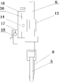
FIG. 5: the structure of the clamp is shown schematically;
FIG. 6: the invention discloses a three-dimensional view of a welding gun two-dimensional adjusting mechanism;
FIG. 7: FIG. 6 is a front view of the present invention;
FIG. 8: the left side view of fig. 6 of the present invention;
FIG. 9: the structure of embodiment 5 of the invention is schematically illustrated;
FIG. 10: a control panel schematic of the apparatus of the present invention;
FIG. 11: the invention relates to an electric principle diagram of an MIG pulse automatic welding device for an electric heating wall hanging water sleeve member;
FIG. 12: the invention relates to a work flow chart of an automatic MIG pulse welding device for an electric heating wall hanging water sleeve member;
wherein, 1-machine table, 2-MIG welding machine, 3-automatic wire feeder, 4-clamp, 5-welding gun, 6-rotary main shaft, 7-round tray rack, 8-positioning device, 9-lifting cylinder, 10-vertical sliding table, 11-first supporting upright post, 12-box body, 13-square shaft sleeve, 14-first door-shaped connecting piece, 15-first connecting block, 16-second door-shaped connecting piece, 17-second connecting block, 18-third connecting block, 19-jig, 1901-disk surface, 1902-through hole, 1903-continuous flange, 1904-horizontal cutting surface, 20-double rotary cylinder, 21-material ejecting mechanism, 22-second supporting upright post, 23-translation cylinder, 24-sliding table fixing plate and 25-horizontal sliding table, 26-a shell, 27-a radiation-proof isolation plate window, 28-a control panel, 29-a translational fastening screw rod and 30-a lifting fastening screw rod.
Detailed Description
In order to better understand the present invention, the following examples are further provided to clearly illustrate the contents of the present invention, but the contents of the present invention are not limited to the following examples. In the following description, numerous specific details are set forth in order to provide a more thorough understanding of the present invention. It will be apparent, however, to one skilled in the art, that the present invention may be practiced without one or more of these specific details. In other instances, well-known features have not been described in order to avoid obscuring the invention.
Example 1
Referring to fig. 1, fig. 2, fig. 3 and fig. 4, electric heat wall hanging water casing spare MIG pulse automatic weld equipment, including board 1, MIG welding machine 2, automatic wire feeder 3, set up liftout mechanism 21, anchor clamps 4 and the welding module on the board 1 and with MIG welding machine 2, automatic wire feeder 3, liftout mechanism 21, anchor clamps 4 and the electric control system that the welding module is signal connection respectively, the welding module include with welder 5 that MIG welding machine 2 is connected, with rotary mechanism that welder 5 is connected and with elevating system that rotary mechanism is connected, rotary mechanism include step motor and with the gyration main shaft 6 that step motor is connected, gyration main shaft 6 sets gradually disk frame 7 and welder two-dimensional adjustment mechanism from top to bottom.
Wherein, the MIG welding machine 2 and the automatic wire feeder 3 are both selected from commercial devices, and are conventional technologies in the field.
The machine table 1 is of a cuboid frame structure, and the top surface is an object placing surface.
The rotating mechanism is driven by a stepping motor through a gear to drive the rotating main shaft 6 to rotate, the welding gun two-dimensional adjusting mechanism is arranged on the rotating main shafts and connected with the welding guns 5, and 360-degree rotation of the rotating mechanism enables the welding guns 5 to realize 360-degree rotation welding, so that the requirements of different welding sites and different welding overlap ratios are met. The lifting mechanism is connected with the rotating mechanism to control the rotating mechanism to lift up and down, and further control the welding gun 5 to lift up and down.
The end part of the rotary main shaft 6 is provided with a positioning device 8, different positioning devices 8 can be selected according to different sizes of workpieces, and the position of the welding gun 5 needs to be correspondingly adjusted. The positioning device 8 is a detachable positioning device 8 which is connected with the end part of the rotary main shaft 6 through a circular shaft sleeve.
The disc frame 7 is arranged on the rotary main shaft 6 to arrange the electronic wire of the welding gun 5, so that the disc frame and the welding gun 5 can rotate synchronously to avoid winding.
The welding gun two-dimensional adjusting mechanism is used for adjusting the welding gun 5 at a plurality of angles so as to meet the requirements of different welding sites.
Referring to fig. 5, the fixture 4 includes a fixture 19 adapted to the electric heating wall hanging water jacket and two rotary cylinders 20 symmetrically disposed on two sides of the fixture 19, and the two rotary cylinders 20 are connected to an electrical control system. After the workpiece is installed on the jig 19, the double rotary cylinders 20 on the two sides of the jig 19 are started, the double rotary cylinders on the left side of the jig 19 rotate 90 degrees rightwards, and the double rotary cylinders on the right side of the jig 19 rotate 90 degrees leftwards, so that the workpiece is held and fixed.
The jig 19 has a flat plate-shaped plate surface 1901, a through hole 1902 is provided on the plate surface, a continuous flange 1903 is provided on the peripheral side of the plate surface, the jig 19 is vertically provided on the surface of the machine table 1, and the upper end portion of the jig 19 has a horizontal cutting surface 1904.
The liftout mechanism 21 sets up the back of tool 19, liftout mechanism 21 includes the liftout cylinder, the liftout cylinder level sets up, the piston rod of liftout cylinder with through-hole 1902 on the tool corresponds, and can penetrate through-hole 1902. The ejection cylinder starts when welding is finished, and a piston rod of the ejection cylinder ejects a workpiece through the through hole, so that the workpiece is convenient to take out.
The end part of the rotary main shaft 6 is connected with a positioning device 8 through a shaft sleeve, and the positioning device is cylindrical, has an arc-shaped end part and is used for assisting in fixing a welding workpiece.
Example 2
The automatic MIG pulse welding equipment for the electric heating wall-hanging water sleeve member described in the embodiment is an improvement on the basis of the embodiment 1, and specifically comprises:
referring to fig. 1, fig. 2, fig. 3 and fig. 4, elevating system includes lift cylinder 9 and vertical slip table 10, set up first support post 11 on the board 1, lift cylinder 9 sets up the top of first support post 11, vertical slip table 10 sets up the side of first support post 11, lift cylinder 9 and electrical control system signal connection.
The stepping motor is arranged in the box body 12 so as to be convenient to install; the box body 12 is connected with a piston rod of the lifting cylinder 9 and movably mounted on the vertical sliding table 10, and the stepping motor is in signal connection with an electrical control system. The stepping motor is arranged in the box body 12, and the box body 12 can be lifted up and down along with the piston rod of the lifting cylinder 9.
Example 3
The automatic MIG pulse welding equipment for the electric heating wall-hanging water sleeve member described in the embodiment is an improvement on the basis of the embodiment 1, and specifically comprises:
referring to fig. 6, 7 and 8, the welding gun two-dimensional adjusting mechanism includes a square shaft sleeve 13 connected to the rotary main shaft 6, a first gate-shaped connecting member 14 connected to the square shaft sleeve 13, and a second gate-shaped connecting member 16 connected to an inner concave surface of the first gate-shaped connecting member 14 through a plurality of screws and a first connecting block 15, wherein a second connecting block 17 is disposed on a back surface of the second gate-shaped connecting member 16, the second connecting block 17 is connected to a third connecting block 18 through a pin, and the third connecting block 18 is connected to the welding gun 5 through a pin.
The welding device comprises a plurality of screws, a first door-shaped connecting piece, a first connecting block, a second door-shaped connecting piece, a second connecting block, a first connecting block, a second connecting block, a first lifting fastening screw, a two-dimensional adjusting mechanism, a welding gun and a rotating mechanism.
Example 4
The automatic MIG pulse welding equipment for the electric heating wall-hanging water sleeve member described in the embodiment is an improvement on the basis of the embodiment 1, and specifically comprises:
referring to fig. 1, 2, 3 and 4, the number of the clamps 4 is two, and the plate surfaces of the two sets of jigs 19 are located on the same vertical surface. And double stations are arranged, so that reciprocating type automatic welding can be performed.
Set up second support post 22 on board 1, the top of second support post 22 sets up translation cylinder 23, the upper portion of first support post 11 and second support post 22 sets up slip table fixed plate 24, set up horizontal slip table 25 on the slip table fixed plate 24, vertical slip table movable mounting be in on the horizontal slip table 25, and with translation cylinder 23's piston rod connection, translation cylinder 23 and electrical control system signal connection.
Referring to fig. 11, the electrical control system includes a power supply, a PLC and a plurality of relays, and the PLC controls the lifting cylinder 9, the stepping motor, the translation cylinder 23, the MIG welder 2 and the automatic wire feeder 3 through the relays, respectively.
The electrical symbols in fig. 11 represent the following material names, respectively: GF is a plastic shell breaker, KM is an alternating current contactor, SF \ SS is normally open/normally closed, and BYD is a text.
Example 5
The automatic MIG pulse welding equipment for the electric heating wall-hanging water sleeve member described in the embodiment is an improvement on the basis of the embodiment 1, and specifically comprises:
referring to fig. 9, the machine table 1, the MIG welder 2 and the automatic wire feeder 3 are all provided with a housing 26, the working area of the machine table 1 is provided with a radiation-proof isolation board window 27, and the side of the machine table 1 is provided with a control panel 28.
The welding area is provided with the radiation-proof isolation plate window, so that the injury of radiation generated during welding to personnel can be reduced.
Referring to fig. 10, the MIG pulse automatic welding equipment control panel 28 is provided with a switch button, a manual/automatic button, a forward/reverse button, a welding gun up/down button, a start button, a stop button, a control emergency stop button, a total power emergency stop button, a power indicator, an operation indicator, a display screen, a buzzer alarm and a one-key start button. The switch button is a power switch, the forward/reverse button is a forward/reverse control button of the stepping motor, the welding gun lifting/lowering button is used for controlling the lifting of the welding gun, the starting button is a welding starting button, and the stopping button is a welding stopping button. The equipment can adopt two operation modes of manual operation and automatic operation.
Referring to fig. 12, the main process of the MIG pulse automatic welding equipment of the invention is to place a workpiece on a jig 19, a double-rotating cylinder 20 presses down to fix the workpiece, a lifting cylinder descends to a welding point, a welding gun 5 starts to arc, a rotary main shaft automatically rotates, a wire feeder starts to feed wires, a MIG welding machine starts to weld, the welding gun 5 finishes welding, the rotary main shaft drives the welding gun to reset upwards, the welded workpiece is withdrawn, the double-rotating cylinder resets, a material ejecting cylinder is opened, the workpiece is reset after being ejected, and the welding operation is repeated in a reciprocating circulation mode.
In practice, the rotation speed of the rotating main shaft of the equipment is preferably set to be in the range of 0.01-10 rpm. The pneumatic lifting stroke of the welding gun is 0-150 mm, and the welding speed is as follows: 1-15 rpm, welding angle: 0-370 DEG, automatic wire feeding speed: 0 to 0.50 mm/s.
And testing the MIG pulse automatic welding equipment. And (4) testing the machine by a technician, inputting parameters according to requirements, checking the machining effect of the workpiece and making professional evaluation.
And (3) testing conditions are as follows:
(1) ambient temperature: -25 ℃ to +55 ℃;
(2) input voltage: three phases [ 380V ] (± 10%);
(3) input voltage frequency: 50 Hz.
The welding speed can be adjusted within the range of 1-15 rpm, the welding angle of the workpiece is 0-370 degrees, and the automatic wire feeding speed of the welding machine is 0-0.50 mm/s. The appearance size and various performance indexes of the processed workpiece meet the standard requirements, and the processing quality of the workpiece is superior to that of the existing production line.
The welding product of the welding equipment is a 2600W electric heating wall hanging water sleeve component, in the welding process, the production efficiency and the product quality are greatly improved, and the problem of welding aging and embrittlement caused by stress expansion deformation and long welding time of a stainless steel sheet is solved.
Finally, the above embodiments are only used for illustrating the technical solutions of the present invention and not for limiting, and other modifications or equivalent substitutions made by the technical solutions of the present invention by those of ordinary skill in the art should be covered within the scope of the claims of the present invention as long as they do not depart from the spirit and scope of the technical solutions of the present invention.
Claims (9)
1. Electric heat hanging water casing spare MIG pulse automatic weld equipment, include board, MIG welding machine, automatic send a machine, set up liftout mechanism, anchor clamps and welding module on the board and with MIG welding machine, automatic send a machine, liftout mechanism, anchor clamps and welding module difference signal connection's electric control system, its characterized in that: the welding module include with welder that the MIG welding machine is connected, with rotary mechanism that welder is connected and with elevating system that rotary mechanism connects, rotary mechanism include step motor and with the gyration main shaft that step motor connects, the gyration main shaft sets gradually disk rack and welder two-dimensional adjustment mechanism from top to bottom.
2. The wall-mounted electric hot water bushing MIG pulse automatic welding device of claim 1, wherein: elevating system includes lift cylinder and vertical slip table, set up first support post on the board, the lift cylinder sets up the top of first support post, vertical slip table sets up the side of first support post.
3. The wall-mounted electric hot water bushing MIG pulse automatic welding device of claim 2, wherein: the stepping motor is arranged in the box body, and the box body is connected with a piston rod of the lifting cylinder and movably installed on the vertical sliding table.
4. The wall-mounted electric hot water bushing MIG pulse automatic welding device of claim 3, wherein: the welding gun two-dimensional adjusting mechanism comprises a square shaft sleeve connected with the rotary main shaft, a first door-shaped connecting piece connected with the square shaft sleeve, and a second door-shaped connecting piece connected with the inner concave surface of the first door-shaped connecting piece through a plurality of screws and a first connecting block, wherein a second connecting block is arranged on the back surface of the second door-shaped connecting piece, the second connecting block is connected with a third connecting block through a screw, and the third connecting block is connected with a welding gun through a screw.
5. The wall-mounted electric hot water sleeve MIG pulse automatic welding device of claim 4, wherein: the fixture comprises a fixture matched with the electric heating wall hanging water jacket and double rotary cylinders symmetrically arranged on two sides of the fixture.
6. The wall-mounted electric hot water sleeve MIG pulse automatic welding device of claim 5, wherein: the jig is provided with a flat plate-shaped disc surface, a through hole is formed in the disc surface, continuous flanges are arranged on the periphery of the disc surface, the jig is vertically arranged on the surface of the machine table, and the upper end portion of the jig is provided with a horizontal cutting surface.
7. The wall-mounted electric hot water sleeve MIG pulse automatic welding device of claim 6, wherein: the fixture is provided with two sets, and the disc surfaces of the two sets of fixtures are positioned on the same vertical surface.
8. The wall-mounted electric hot water bushing MIG pulse automatic welding device of claim 7, wherein: the improved horizontal sliding table is characterized in that a second supporting stand column is arranged on the table, a translation cylinder is arranged at the top of the second supporting stand column, a sliding table fixing plate is arranged on the upper portions of the first supporting stand column and the second supporting stand column, a horizontal sliding table is arranged on the sliding table fixing plate, and a vertical sliding table is movably mounted on the horizontal sliding table and connected with a piston rod of the translation cylinder.
9. The wall-mounted electric hot water sleeve MIG pulse automatic welding device of claim 8, wherein: the ejection mechanism is arranged on the back face of the jig and comprises an ejection cylinder, the ejection cylinder is horizontally arranged, and a piston rod of the ejection cylinder corresponds to the through hole in the jig and can penetrate into the through hole.
Priority Applications (1)
| Application Number | Priority Date | Filing Date | Title |
|---|---|---|---|
| CN201911395192.XA CN110977115B (en) | 2019-12-30 | 2019-12-30 | Automatic MIG pulse welding equipment for electric heating wall-mounted water casing pipe |
Applications Claiming Priority (1)
| Application Number | Priority Date | Filing Date | Title |
|---|---|---|---|
| CN201911395192.XA CN110977115B (en) | 2019-12-30 | 2019-12-30 | Automatic MIG pulse welding equipment for electric heating wall-mounted water casing pipe |
Publications (2)
| Publication Number | Publication Date |
|---|---|
| CN110977115A true CN110977115A (en) | 2020-04-10 |
| CN110977115B CN110977115B (en) | 2021-08-24 |
Family
ID=70078901
Family Applications (1)
| Application Number | Title | Priority Date | Filing Date |
|---|---|---|---|
| CN201911395192.XA Active CN110977115B (en) | 2019-12-30 | 2019-12-30 | Automatic MIG pulse welding equipment for electric heating wall-mounted water casing pipe |
Country Status (1)
| Country | Link |
|---|---|
| CN (1) | CN110977115B (en) |
Cited By (6)
| Publication number | Priority date | Publication date | Assignee | Title |
|---|---|---|---|---|
| CN111774778A (en) * | 2020-08-03 | 2020-10-16 | 广东技术师范大学 | Rotary arm support for robot |
| CN112091364A (en) * | 2020-09-18 | 2020-12-18 | 一重集团大连核电石化有限公司 | Welding head for deep hole surfacing |
| CN112192006A (en) * | 2020-09-03 | 2021-01-08 | 中国化学工程第六建设有限公司 | All-position automatic argon arc welding rapid argon filling protection system |
| CN112453651A (en) * | 2020-11-09 | 2021-03-09 | 孙亚林 | Electric power fitting production is with crooked type equalizer ring processingequipment |
| CN113523517A (en) * | 2021-07-22 | 2021-10-22 | 周功标 | Adjustable multistation pipeline welding equipment |
| CN116135388A (en) * | 2023-04-19 | 2023-05-19 | 沧州友发管道装备有限公司 | Forming and welding equipment and method for large-caliber spiral steel pipe |
Citations (6)
| Publication number | Priority date | Publication date | Assignee | Title |
|---|---|---|---|---|
| CN104175150A (en) * | 2014-08-10 | 2014-12-03 | 强胜精密机械(苏州)有限公司 | Pressure casting transformed special-shaped product hole positioning pneumatic clamp and clamping method |
| CN104308326A (en) * | 2014-09-30 | 2015-01-28 | 芜湖炬胜机电设备厂 | Automatic welding device and welding process thereof |
| CN105201036A (en) * | 2015-10-12 | 2015-12-30 | 广西玉柴重工有限公司 | Pipe grabbing device |
| CN205629634U (en) * | 2016-05-11 | 2016-10-12 | 广州海可姆机电科技有限公司 | Automatic change MIG welding set |
| CN108067779A (en) * | 2016-11-11 | 2018-05-25 | 江苏天南电力器材有限公司 | Yoke plate casing automatic welding device |
| CN209175145U (en) * | 2018-10-31 | 2019-07-30 | 南通永成工业自动化有限公司 | Brake-shoe longitudinal seam welding equipment |
-
2019
- 2019-12-30 CN CN201911395192.XA patent/CN110977115B/en active Active
Patent Citations (6)
| Publication number | Priority date | Publication date | Assignee | Title |
|---|---|---|---|---|
| CN104175150A (en) * | 2014-08-10 | 2014-12-03 | 强胜精密机械(苏州)有限公司 | Pressure casting transformed special-shaped product hole positioning pneumatic clamp and clamping method |
| CN104308326A (en) * | 2014-09-30 | 2015-01-28 | 芜湖炬胜机电设备厂 | Automatic welding device and welding process thereof |
| CN105201036A (en) * | 2015-10-12 | 2015-12-30 | 广西玉柴重工有限公司 | Pipe grabbing device |
| CN205629634U (en) * | 2016-05-11 | 2016-10-12 | 广州海可姆机电科技有限公司 | Automatic change MIG welding set |
| CN108067779A (en) * | 2016-11-11 | 2018-05-25 | 江苏天南电力器材有限公司 | Yoke plate casing automatic welding device |
| CN209175145U (en) * | 2018-10-31 | 2019-07-30 | 南通永成工业自动化有限公司 | Brake-shoe longitudinal seam welding equipment |
Cited By (9)
| Publication number | Priority date | Publication date | Assignee | Title |
|---|---|---|---|---|
| CN111774778A (en) * | 2020-08-03 | 2020-10-16 | 广东技术师范大学 | Rotary arm support for robot |
| CN112192006A (en) * | 2020-09-03 | 2021-01-08 | 中国化学工程第六建设有限公司 | All-position automatic argon arc welding rapid argon filling protection system |
| CN112192006B (en) * | 2020-09-03 | 2022-04-29 | 中国化学工程第六建设有限公司 | All-position automatic argon arc welding rapid argon filling protection system |
| CN112091364A (en) * | 2020-09-18 | 2020-12-18 | 一重集团大连核电石化有限公司 | Welding head for deep hole surfacing |
| CN112091364B (en) * | 2020-09-18 | 2022-01-21 | 一重集团大连核电石化有限公司 | Welding head for deep hole surfacing |
| CN112453651A (en) * | 2020-11-09 | 2021-03-09 | 孙亚林 | Electric power fitting production is with crooked type equalizer ring processingequipment |
| CN113523517A (en) * | 2021-07-22 | 2021-10-22 | 周功标 | Adjustable multistation pipeline welding equipment |
| CN113523517B (en) * | 2021-07-22 | 2022-09-23 | 安徽盈创石化检修安装有限责任公司 | Adjustable multistation pipeline welding equipment |
| CN116135388A (en) * | 2023-04-19 | 2023-05-19 | 沧州友发管道装备有限公司 | Forming and welding equipment and method for large-caliber spiral steel pipe |
Also Published As
| Publication number | Publication date |
|---|---|
| CN110977115B (en) | 2021-08-24 |
Similar Documents
| Publication | Publication Date | Title |
|---|---|---|
| CN110977115B (en) | Automatic MIG pulse welding equipment for electric heating wall-mounted water casing pipe | |
| CN202344110U (en) | Sleeve welding machine | |
| CN109702283B (en) | Full-automatic welding pressure-sensitive machine | |
| CN110977112B (en) | TIG pulse automatic welding equipment | |
| CN220073682U (en) | Automatic welding device for automobile parts | |
| CN213469921U (en) | Special XY-axis vertical girth welding machine | |
| CN217551400U (en) | Equipment for automatically welding magnesium-aluminum alloy goods shelves and trays in vertical warehouse by robot | |
| CN110116285B (en) | Automatic gear welding mechanism who changes | |
| CN217965218U (en) | Automatic change many welder welding equipment | |
| CN115365626A (en) | Plasma welding system for intelligent robot | |
| CN114985866A (en) | Induction brazing machine | |
| CN102085594B (en) | Automatic netting four-taper-sleeve welding machine and automatic welding method thereof | |
| CN210413376U (en) | Automatic assembling machine for lampshade of electric welding pliers | |
| CN109967824B (en) | Two-sided sharp welding equipment of intelligence | |
| CN208162916U (en) | A kind of robot welding system of the rotary clamp device of band | |
| CN214978787U (en) | Brushless motor winding welding equipment | |
| CN110877178A (en) | Automatic welding device for circular pipe fittings | |
| CN218749383U (en) | Servo hot plate welding machine | |
| CN218169028U (en) | Shaft hole spiral welding tool | |
| CN220127898U (en) | Feeding mechanism of laser welding machine | |
| CN216182855U (en) | Hot melting machine capable of realizing automatic feeding and discharging | |
| CN220347572U (en) | Rivet welding tool | |
| CN219113223U (en) | Frame welding device | |
| CN219818438U (en) | Automatic change welding frock | |
| CN214418028U (en) | Automatic welding device based on lathe |
Legal Events
| Date | Code | Title | Description |
|---|---|---|---|
| PB01 | Publication | ||
| PB01 | Publication | ||
| SE01 | Entry into force of request for substantive examination | ||
| SE01 | Entry into force of request for substantive examination | ||
| GR01 | Patent grant | ||
| GR01 | Patent grant |