CN110966168B - Sand setting and exhausting device of plunger pump - Google Patents
Sand setting and exhausting device of plunger pump Download PDFInfo
- Publication number
- CN110966168B CN110966168B CN201911312992.0A CN201911312992A CN110966168B CN 110966168 B CN110966168 B CN 110966168B CN 201911312992 A CN201911312992 A CN 201911312992A CN 110966168 B CN110966168 B CN 110966168B
- Authority
- CN
- China
- Prior art keywords
- liquid
- solid
- exhaust
- liquid separation
- gas
- Prior art date
- Legal status (The legal status is an assumption and is not a legal conclusion. Google has not performed a legal analysis and makes no representation as to the accuracy of the status listed.)
- Active
Links
Images


Classifications
-
- F—MECHANICAL ENGINEERING; LIGHTING; HEATING; WEAPONS; BLASTING
- F04—POSITIVE - DISPLACEMENT MACHINES FOR LIQUIDS; PUMPS FOR LIQUIDS OR ELASTIC FLUIDS
- F04B—POSITIVE-DISPLACEMENT MACHINES FOR LIQUIDS; PUMPS
- F04B47/00—Pumps or pumping installations specially adapted for raising fluids from great depths, e.g. well pumps
-
- B—PERFORMING OPERATIONS; TRANSPORTING
- B01—PHYSICAL OR CHEMICAL PROCESSES OR APPARATUS IN GENERAL
- B01D—SEPARATION
- B01D19/00—Degasification of liquids
-
- B—PERFORMING OPERATIONS; TRANSPORTING
- B01—PHYSICAL OR CHEMICAL PROCESSES OR APPARATUS IN GENERAL
- B01D—SEPARATION
- B01D21/00—Separation of suspended solid particles from liquids by sedimentation
- B01D21/02—Settling tanks with single outlets for the separated liquid
-
- B—PERFORMING OPERATIONS; TRANSPORTING
- B01—PHYSICAL OR CHEMICAL PROCESSES OR APPARATUS IN GENERAL
- B01D—SEPARATION
- B01D21/00—Separation of suspended solid particles from liquids by sedimentation
- B01D21/26—Separation of sediment aided by centrifugal force or centripetal force
-
- F—MECHANICAL ENGINEERING; LIGHTING; HEATING; WEAPONS; BLASTING
- F04—POSITIVE - DISPLACEMENT MACHINES FOR LIQUIDS; PUMPS FOR LIQUIDS OR ELASTIC FLUIDS
- F04B—POSITIVE-DISPLACEMENT MACHINES FOR LIQUIDS; PUMPS
- F04B47/00—Pumps or pumping installations specially adapted for raising fluids from great depths, e.g. well pumps
- F04B47/005—Sand trap arrangements
-
- F—MECHANICAL ENGINEERING; LIGHTING; HEATING; WEAPONS; BLASTING
- F04—POSITIVE - DISPLACEMENT MACHINES FOR LIQUIDS; PUMPS FOR LIQUIDS OR ELASTIC FLUIDS
- F04B—POSITIVE-DISPLACEMENT MACHINES FOR LIQUIDS; PUMPS
- F04B53/00—Component parts, details or accessories not provided for in, or of interest apart from, groups F04B1/00 - F04B23/00 or F04B39/00 - F04B47/00
- F04B53/10—Valves; Arrangement of valves
- F04B53/1002—Ball valves
Abstract
The invention relates to a sand setting exhaust device of a plunger pump, which comprises a plunger, a pump barrel, a traveling valve, an exhaust gas separator assembly and a solid-liquid separation assembly, wherein the plunger is arranged in the pump barrel; the exhaust and gas separator assembly comprises offset exhaust separators and overflow exhaust pipes which are symmetrically arranged, the bottom ends of the offset exhaust separators are provided with tangential liquid inlet ports, and gas-liquid separation conical sections are connected with a tail exhaust pipe; the solid-liquid separation assembly comprises a liquid inlet distribution disc, a solid-phase deposition shell and a gravity settling tank, the liquid inlet distribution disc is connected to the upper port of the solid-phase deposition shell, the gravity settling tank is arranged in the solid-phase deposition shell, and a plurality of solid-liquid separation cups are arranged on the periphery of the gravity settling tank. The invention plays a role in exhausting and preventing sand, thereby improving the pump efficiency and prolonging the service life of the pump.
Description
The technical field is as follows:
the invention relates to the field of oil field oil extraction engineering devices, in particular to a sand setting and exhausting device of a plunger pump.
Background art:
at present, the land oil extraction is mainly carried out in two modes, namely self-injection oil extraction and mechanical oil extraction. Mechanical oil extraction is further divided into sucker-rod pump, rodless pump and gas lift method. Based on the current situation of exploring and developing oil fields in China, land exploitation is still the main field of crude oil exploitation, and mechanical oil exploitation is a generally applicable oil exploitation means for land exploitation. Therefore, how to improve the exploitation capability and reduce the loss is an urgent problem to be solved in the oil field.
After years of development of oil fields in China, most of the oil fields enter the middle and later stages of exploitation, and produced liquid often has the current situations of high sand ratio, high water content, high gas content, high thick oil, high polymer flooding and the like. Under the complex working conditions, the plunger oil well pump is frequently subjected to sand blocking, sand burying, sand grinding pump barrel and air locking in the crude oil extraction process, so that the pump inspection period of the plunger pump well is shorter and shorter, and the oil field extraction is seriously influenced.
Therefore, a new exhaust sand prevention device is designed for the plunger pump, the sand phase and the gas phase entering the plunger oil well pump are effectively reduced, and the plunger pump has important significance.
The invention content is as follows:
the invention aims to provide a sand setting and exhausting device of a plunger pump, which is used for solving the problems of sand blocking, air locking and the like in the operation process of the oil well pump at present.
The technical scheme adopted by the invention for solving the technical problems is as follows: the sand setting and exhausting device of the plunger pump comprises a plunger, a pump cylinder, a traveling valve, an exhaust separator assembly and a solid-liquid separation assembly, wherein the plunger is arranged in the pump cylinder;
the exhaust-gas separator assembly comprises offset exhaust-gas separators which are symmetrically arranged, the bottom end of each offset exhaust-gas separator is provided with a tangential liquid inlet, an overflow exhaust pipe is arranged in each offset exhaust-gas separator, a plurality of exhaust ports are unevenly arranged on each overflow exhaust pipe, the inner cavity of each offset exhaust-gas separator above each overflow exhaust pipe is conical to form a gas-liquid separation conical section, each gas-liquid separation conical section is connected with a liquid exhaust tail pipe, and the liquid exhaust tail pipes are collected at the outlets of the separators;
the solid-liquid separation assembly comprises a liquid supply splitter disc, a solid-phase deposition shell and a gravity settling tank, the liquid supply splitter disc is connected to the upper port of the solid-phase deposition shell, the gravity settling tank is arranged in the solid-phase deposition shell, an outlet of the gravity settling tank penetrates out of the liquid supply splitter disc and extends into a ball seat of a fixed valve, a plurality of solid-liquid separation cups are arranged around the gravity settling tank, the solid-liquid separation cups are connected with the gravity settling tank through a liquid-phase tail flow port at the bottom of the solid-liquid separation cups, and the gravity settling tank is provided with a sand discharge valve; the outer and the inlayer of coming liquid flow distribution disc form the intermediate layer cavity, and the outer liquid entry that sets up that comes, and the inlayer sets up a plurality of diffluence orifices, and every diffluence orifice connects the upper portion entry of a solid-liquid separation cup, and solid-liquid separation cup from the top down is acceleration section, conic section, export section in proper order, and acceleration section sets up centrifugal accelerator, and the conic section is the back taper, and conic section portion is for having set up wedge sand discharge mouth, and the conic section is provided with a plurality of solid phase wedge exports, and the export section sets up the liquid phase tail-flow mouth.
The solid-liquid separation cup has 4 in the above scheme, and is uniformly arranged around the gravity settling tank along the circumferential direction.
Come liquid splitter plate's outer evenly set up 2 and come the liquid entry in above-mentioned scheme, and the inlayer sets up 4 diffluent mouths.
According to the scheme, the middle flowing valve comprises a floating valve ball and a floating valve cover, the floating valve ball is arranged in the floating valve cover, and the lower end of the floating valve is connected with the exhaust separator assembly through an upper connector.
The standing valve assembly includes standing valve ball, standing valve cover, fixed disk seat among the above-mentioned scheme, and the standing valve cover upper end links to each other with row gas separator assembly through the lower joint, and the standing valve cover lower extreme links to each other with the standing valve ball seat, and the standing valve ball seat lower extreme links to each other with gravity settling cask upper end, and the standing valve ball sets up inside the standing valve cover.
The outer two liquid inlets of the incoming liquid flow distribution disc in the scheme realize the collection of the produced liquid, the 4 flow distribution ports on the inner layer realize the flow distribution of the produced liquid into the solid-liquid separation cup respectively, the solid-liquid separation cup realizes the primary first-stage cyclone separation of the solid-liquid separation in the produced liquid, the gravity settling tank realizes the secondary gravity separation of the solid-liquid separation in the produced liquid, and meanwhile, the form combination of the first-stage cyclone separation and the secondary gravity separation is realized, the effective reduction of sand phase particles in the pump is realized, and the phenomena of sand blocking and sand blockage which often occur in the pump are weakened.
The working process of the exhaust separator assembly in the scheme is as follows: the produced liquid enters the interior of the offset gas-discharge separator through the tangential liquid inlet, primary tangential acceleration is carried out, secondary tangential acceleration is carried out in the gas-liquid separation conical section, the condensate gas and the dissolved gas in the produced liquid are reduced through the cyclone separation effect, the gas phase in the produced liquid is gathered around the overflow cylindrical section and is discharged out of the pump barrel from the gas outlet, and the liquid phase in the produced liquid is discharged along the liquid discharge tail pipe and is gathered into the pump barrel.
The invention has the following beneficial effects:
the solid-liquid separation cup realizes the primary first-stage cyclone separation of solid-liquid separation in the produced liquid, the gravity settling tank realizes the further second-stage gravity separation of the solid-liquid separation in the produced liquid, and simultaneously realizes the combination of the forms of the first-stage cyclone separation and the second-stage gravity separation, thereby realizing the effective reduction of sand phase particles in the pump and weakening the phenomena of sand blocking and sand blockage frequently occurring in the pump; the exhaust separator assembly connected with the upper end of the fixed valve cover realizes the separation of gas and avoids the phenomenon of air lock caused by the fact that a large amount of gas enters the pump cylinder. The reciprocating circulation makes the plunger oil pump play the purpose of exhausting and preventing sand, thereby improving the pump efficiency and prolonging the service life of the pump.
Fourthly, explanation of the attached drawings:
FIG. 1 is a schematic diagram of the present invention.
Fig. 2 is a schematic view of the structure of the stationary valve housing of the present invention.
Fig. 3 is a schematic structural view of the incoming liquid flow distribution plate of the present invention.
FIG. 4 is a schematic view of the structure of the centrifugal accelerator according to the present invention.
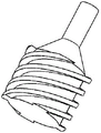
FIG. 5 is a schematic structural view of a solid-liquid separation cup according to the present invention.
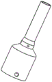
FIG. 6 is a schematic diagram of the gravity settling tank of the present invention.
FIG. 7 is a schematic view showing the connection relationship between the incoming liquid flow-dividing disk, the solid-liquid separation cup and the gravity settling tank in the present invention.
Fig. 8 is an enlarged view at i of fig. 1.
Fig. 9 is an enlarged view of fig. 1 at ii.
In the figure, 1, a plunger 2, a pump cylinder 3, a floating valve ball 4, an upper connector 5, an offset gas-discharging separator 5-1, a liquid discharging tail pipe 5-2, a gas-liquid separation conical section 5-3, an exhaust port 5-4, a tangential liquid inlet 6, a lower connector 7, a fixed valve ball 8, a fixed valve cover 9, a fixed valve seat 10, a gravity settling tank 11, an incoming liquid flow distribution disc 11-1, an incoming liquid inlet 11-2, a flow distribution port 12, a solid-liquid separation cup 12-1, a centrifugal accelerator 12-2, a solid phase wedge-shaped outlet 12-3, a liquid phase tail flow port 13, a sand discharging valve 14 and a solid phase settling shell.
Detailed Description
The invention is further described below with reference to the accompanying drawings:
as shown in figure 1, the sand setting and exhausting device of the plunger pump comprises a plunger 1, a pump cylinder 2, a traveling valve, a fixed valve assembly, an exhaust separator assembly and a solid-liquid separation assembly. The floating valve ball 3 is placed in the plunger 1, the plunger 1 is placed in the pump barrel 2, the pump barrel 2 is connected with the upper end of the upper connector 4, the lower end of the upper connector 4 is connected with the exhaust gas separator assembly, the lower end of the exhaust gas separator assembly is connected with the lower connector 6, the fixed valve ball 7 is placed in the fixed valve cover 8, the fixed valve seat 9 is connected with the upper end of the gravity settling tank 10, the solid-liquid separation cup 12 is connected with the gravity settling tank 10, and the gravity settling tank 10 and the solid-liquid separation cup 12 are placed in the solid-phase settling shell 14 together.
The fixed valve assembly comprises a fixed valve ball 7, a fixed valve cover 8 and a fixed valve seat 9, the upper end of the fixed valve cover 8 is connected with the offset gas-discharge separator 5 through a lower connector 6, the lower end of the fixed valve cover 8 is connected with the fixed valve seat 9, the lower end of the fixed valve seat 9 is connected with the upper end of the gravity settling tank 10, the fixed valve ball 7 is arranged inside the fixed valve cover 8, a lengthened coupling is arranged inside the fixed valve cover 8, the fixed valve ball 7 is propped against the valve ball in the floating process, and the inner wall flow passage hole can ensure the passage of fluid. The fixed valve housing is seen in fig. 2.
The exhaust gas separator assembly is positioned between the upper joint 4 and the lower joint 6 and consists of a left offset exhaust gas separator 5 and a right offset exhaust gas separator 5. Referring to fig. 8, an offset gas-discharging separator 5 is provided with a tangential liquid inlet 5-4, incoming liquid of the offset gas-discharging separator enters from the side wall through the tangential liquid inlet 5-4 and has a certain tangential speed, so that the produced liquid is subjected to rotational flow acceleration in the offset gas-discharging separator 5, a gas-liquid separation conical section 5-2 in the offset gas-discharging separator is a main separation section of liquid and gas under the action of rotational flow separation, gas phase is gathered around an overflow cylindrical section in the offset gas-discharging separator, holes are unevenly distributed on two sides of the surface of an overflow gas-discharging pipe to serve as gas outlets (the gas outlets 5-3 are formed by drilling small holes around the overflow cylindrical section), in the rotational flow separation process, gas phase is discharged out of a pump cylinder 2 from the gas outlets 5-3, and liquid on two sides continuously collects and flows upwards through a tail pipe 5, and out the outlet at the top. The exhaust separator assembly realizes the separation of gas, and avoids a large amount of gas from entering the pump barrel 2, thereby avoiding the gas lock phenomenon caused to the pump. The reciprocating circulation makes the plunger oil pump play the purpose of exhausting and preventing sand, thereby improving the pump efficiency and prolonging the service life of the pump.
The solid-liquid separation assembly comprises an incoming liquid flow distribution disc 11, a solid-phase deposition shell 14, a gravity settling tank 10 and a solid-liquid separation cup 12, wherein the solid-liquid separation cup is formed by circumferentially surrounding and parallelly connecting 4 solid-liquid separation cups at 90 degrees (as shown in figure 7), liquid phase tail flow ports 12-3 of the 4 solid-liquid separation cups are respectively in threaded connection with 4 circumferential inlets of the gravity settling tank 10, the 4 inlets of the solid-liquid separation cups are surrounded and connected through the incoming liquid flow distribution disc 11 to form two general incoming liquid inlets 11-1 on the left side and the right side, and the connected incoming liquid flow distribution disc 11, the gravity settling tank 10 and the 4 solid-liquid separation cups 12 are jointly arranged inside the solid-phase deposition shell 14 to form the solid-liquid separation assembly. The outlet of the gravity settling tank penetrates out of the liquid diversion disc 11 and extends into the fixed valve seat 9, the bottom end of the right side of the gravity settling tank 10 is provided with a sand unloading valve 13, and when the sand phase accumulated in the gravity settling tank 10 is too much, the sand unloading valve 13 is opened to perform internal sand cleaning. The gravity settling tank 10 is shown in figure 6.
Referring to fig. 3, the outer layer and the inner layer of the incoming liquid flow distribution plate 11 form an interlayer cavity, the outer layer is provided with an incoming liquid inlet 11-1, the inner layer is provided with a plurality of flow distribution ports, and each flow distribution port is connected with an upper inlet of a solid-liquid separation cup 12.
With reference to fig. 5 and 9, the solid-liquid separation cup 12 comprises an acceleration section, a conical section and an outlet section from top to bottom in sequence, wherein the acceleration section is provided with a centrifugal accelerator 12-1, the conical section is in an inverted cone shape, the conical section is provided with a wedge-shaped sand discharge port, the conical section is provided with a plurality of solid-phase wedge-shaped outlets 12-2, and the outlet section is provided with a liquid-phase tail flow port 12-3. The centrifugal accelerator is shown in figure 4.
When the invention works, the plunger 1 is driven by the motor to do up-and-down reciprocating motion, when the plunger 1 moves upwards, the space in the pump barrel 2 is enlarged, the pressure is reduced, the floating valve ball 3 is closed, the fixed valve ball 7 is opened under the action of the silence and the pressure difference in the pump cavity, the produced liquid enters the incoming liquid distribution disc 11 from the incoming liquid inlets 11-1 at the two sides of the incoming liquid distribution disc 11, the collected liquid enters the solid-liquid separation cup 12 from the distribution ports 11-2 of 4 parallel incoming liquid distribution discs, the positions of the incoming liquid distribution ports 11-2 are tangential inlets relative to the solid-liquid separation cup 12, the liquid at the moment obtains primary tangential acceleration and has a certain rotational flow separation effect, the two-stage acceleration is obtained by the action of the centrifugal accelerator 12-1 in the advancing process of the liquid, and the produced liquid can carry out three-stage acceleration in the conical section part of the solid-liquid separation cup 12, so that the solid sand phase in the produced liquid is thrown out along the solid phase wedge-shaped outlet 12-2 and falls into the solid phase deposition shell 14, and the treatment capacity of the incoming liquid is increased by the 4 solid-liquid separation cups 12 connected in parallel, thereby ensuring the effective separation. At the moment, the produced liquid containing part of solid-phase substances separated by the cyclone separation in the solid-liquid separation cup 12 enters the gravity settling tank 10 through the liquid-phase tail flow port 12-3, and some solid-phase particles can be deposited at the bottom of the settling tank under the action of gravity, so that the combined separation of primary cyclone separation and secondary gravity separation is realized. At the moment, the produced liquid contains a very small amount of solid-phase substances, the produced liquid enters the interior of the exhaust gas separator with two sides offset through a liquid tangential liquid inlet 5-4 of the offset exhaust gas separator, the entering liquid has a certain tangential speed and is subjected to primary acceleration, secondary acceleration is performed in a gas-liquid separation conical section 5-2, some dissolved gases in the produced liquid are subjected to cyclone separation, gas phases are gathered around an overflow cylindrical section of the offset exhaust gas separator 5, the gas phases are discharged out of the pump cylinder from an exhaust port 5-3, liquid phases are discharged along a liquid discharge tail pipe 5-1 and are gathered into the pump cylinder 2, and the condensate gases and the dissolved gases in the produced liquid are reduced by the offset exhaust gas separator 5 through the cyclone separation. When the plunger 1 moves downwards, the space in the pump barrel 3 is reduced, the floating valve ball 3 is opened under pressure, the fixed valve ball 7 is closed, and the produced liquid is pumped to the upper part through the plunger. Repeating the steps to finish the oil pumping, air exhausting and sand prevention work of the plunger pump.
The sand setting and exhausting device of the plunger pump ensures that the plunger pump can effectively prevent sand and play a key exhausting role at the same time in the working process, and can obviously reduce the phenomena of sand blocking, air locking and the like which often occur in the pump.
Claims (7)
1. The utility model provides a sand setting exhaust apparatus of plunger pump which characterized in that: the sand setting and exhausting device of the plunger pump comprises a plunger (1), a pump cylinder (2), a traveling valve, an exhaust separator assembly and a solid-liquid separation assembly, wherein the plunger (1) is arranged in the pump cylinder (2), the lower end of a traveling valve ball (3) is provided with the exhaust separator assembly, the lower end of the exhaust separator assembly is provided with a fixed valve assembly, and the lower end of the fixed valve assembly is provided with the solid-liquid separation assembly;
the exhaust gas separator assembly comprises offset exhaust gas separators which are symmetrically arranged, the bottom end of each offset exhaust gas separator is provided with a tangential liquid inlet (5-4), an overflow exhaust pipe is arranged in each offset exhaust gas separator, the overflow exhaust pipe is unevenly provided with a plurality of exhaust ports (5-3), the inner cavity of each offset exhaust gas separator above the overflow exhaust pipe is conical to form a gas-liquid separation conical section (5-2), the gas-liquid separation conical section (5-2) is connected with a liquid exhaust tail pipe (5-1), and the liquid exhaust tail pipes (5-1) are collected at the outlet of the separator;
the solid-liquid separation assembly comprises an incoming liquid flow distribution disc (11), a solid-phase deposition shell (14) and a gravity settling tank (10), the incoming liquid flow distribution disc (11) is connected to the upper end opening of the solid-phase deposition shell (14), the gravity settling tank (10) is arranged in the solid-phase deposition shell (14), the outlet of the gravity settling tank penetrates out of the incoming liquid flow distribution disc (11) and extends into a fixed valve seat (9), a plurality of solid-liquid separation cups (12) are arranged on the periphery of the gravity settling tank (10), the solid-liquid separation cups (12) are connected with the gravity settling tank (10) through a liquid-phase tail flow opening (12-3) at the bottom of the solid-liquid separation cups, and the gravity settling tank (10) is provided with a sand discharge valve (13; an interlayer cavity is formed by the outer layer and the inner layer of an incoming liquid flow distribution disc (11), an incoming liquid inlet (11-1) is formed in the outer layer, a plurality of flow distribution ports (11-2) are formed in the inner layer, each flow distribution port (11-2) is connected with an upper inlet of a solid-liquid separation cup (12), the solid-liquid separation cups (12) sequentially comprise an acceleration section, a conical section and an outlet section from top to bottom, a centrifugal accelerator (12-1) is arranged on the acceleration section, the conical section is in an inverted cone shape and provided with a plurality of solid-phase wedge-shaped outlets (12-2), and a liquid-phase tail flow port (12-3) is formed in the outlet.
2. The sand setting exhaust device of a plunger pump according to claim 1, characterized in that: the number of the solid-liquid separation cups (12) is 4, and the solid-liquid separation cups are uniformly arranged around the gravity settling tank (10) along the circumferential direction.
3. The sand setting exhaust device of a plunger pump according to claim 2, characterized in that: come the liquid splitter plate (11) the outer 2 liquid inlets that evenly set up, the inlayer sets up 4 diffluent mouths.
4. The sand setting exhaust device of a plunger pump according to claim 3, characterized in that: the traveling valve comprises a traveling valve ball (3) and a traveling valve cover, the traveling valve ball (3) is arranged in the traveling valve cover, and the lower end of the traveling valve is connected with the exhaust separator assembly through an upper connector (4).
5. The sand setting exhaust device of a plunger pump according to claim 4, characterized in that: the fixed valve assembly comprises a fixed valve ball (7), a fixed valve cover (8) and a fixed valve seat (9), the upper end of the fixed valve cover (8) is connected with the exhaust-gas separator assembly through a lower joint (6), the lower end of the fixed valve cover (8) is connected with the fixed valve seat (9), the lower end of the fixed valve seat (9) is connected with the upper end of a gravity settling tank (10), and the fixed valve ball (7) is arranged inside the fixed valve cover (8).
6. The sand setting exhaust device of a plunger pump according to claim 5, characterized in that: come two outer liquid inlets that come of liquid flow distribution disc (11), realized the collection to the extraction liquid, the reposition of redundant personnel that the extraction liquid entered into respectively in solid-liquid separation cup (12) has been realized to 4 diffluent mouths in the inner layer, solid-liquid separation cup (12) have realized the preliminary one-level hydrocyclone separation of solid-liquid separation in the extraction liquid, gravity settling tank (10) have realized the second grade gravity separation of solid-liquid separation in the extraction liquid, the formal combination of one-level hydrocyclone separation and second grade gravity separation has been realized simultaneously, realize the effective reduction to the interior sand phase granule of pump, the sand card that often takes place in the pump, sand blocking phenomenon weaken.
7. The sand setting exhaust device of a plunger pump according to claim 6, characterized in that: the working process of the exhaust separator assembly is as follows: the produced liquid enters the interior of the offset gas-discharge separator (5) through the tangential liquid inlet (5-4) to be subjected to primary tangential acceleration, then is subjected to secondary tangential acceleration in the gas-liquid separation conical section, condensate gas and dissolved gas in the produced liquid are reduced through the cyclone separation effect, gas phase in the produced liquid is gathered around the overflow cylindrical section and is discharged out of the pump barrel from the gas outlet (5-3), and liquid phase in the produced liquid is discharged along the liquid discharge tail pipe and is collected into the pump barrel.
Priority Applications (1)
| Application Number | Priority Date | Filing Date | Title |
|---|---|---|---|
| CN201911312992.0A CN110966168B (en) | 2019-12-18 | 2019-12-18 | Sand setting and exhausting device of plunger pump |
Applications Claiming Priority (1)
| Application Number | Priority Date | Filing Date | Title |
|---|---|---|---|
| CN201911312992.0A CN110966168B (en) | 2019-12-18 | 2019-12-18 | Sand setting and exhausting device of plunger pump |
Publications (2)
| Publication Number | Publication Date |
|---|---|
| CN110966168A CN110966168A (en) | 2020-04-07 |
| CN110966168B true CN110966168B (en) | 2021-03-23 |
Family
ID=70035151
Family Applications (1)
| Application Number | Title | Priority Date | Filing Date |
|---|---|---|---|
| CN201911312992.0A Active CN110966168B (en) | 2019-12-18 | 2019-12-18 | Sand setting and exhausting device of plunger pump |
Country Status (1)
| Country | Link |
|---|---|
| CN (1) | CN110966168B (en) |
Citations (8)
| Publication number | Priority date | Publication date | Assignee | Title |
|---|---|---|---|---|
| CN85202069U (en) * | 1985-06-03 | 1986-03-19 | 天津市电机厂 | Oil and gas seperating device of latent oil pump |
| CN200955384Y (en) * | 2006-09-23 | 2007-10-03 | 中国石化股份胜利油田分公司海洋采油厂 | Oil-gas separator for electric submersible pump |
| CN202152675U (en) * | 2011-04-25 | 2012-02-29 | 于成龙 | Rotational-flow high-efficient sand setting device |
| CN202300956U (en) * | 2011-08-31 | 2012-07-04 | 中国石油化工股份有限公司 | Rotational flow side draught oil suction pump |
| CN203879482U (en) * | 2014-04-25 | 2014-10-15 | 西南石油大学 | Pumping well spiral-flow type separator |
| CN204627948U (en) * | 2015-04-28 | 2015-09-09 | 中国石油天然气股份有限公司 | Oil well deep oil well pump |
| CN109083831A (en) * | 2018-08-21 | 2018-12-25 | 东北石油大学 | A kind of self-sealing drag reduction anti-seizing oil pump |
| CN110485970A (en) * | 2019-09-18 | 2019-11-22 | 东北石油大学 | A kind of exhaust sand control installation for oil well pump |
Family Cites Families (2)
| Publication number | Priority date | Publication date | Assignee | Title |
|---|---|---|---|---|
| US6702027B2 (en) * | 2001-12-18 | 2004-03-09 | Baker Hughes Incorporated | Gas dissipation chamber for through tubing conveyed ESP pumping systems |
| US20190309612A1 (en) * | 2018-04-04 | 2019-10-10 | Harbison-Fischer, Inc. | Downhole pumps with outside pressure balancing and sand separation and isolation |
-
2019
- 2019-12-18 CN CN201911312992.0A patent/CN110966168B/en active Active
Patent Citations (8)
| Publication number | Priority date | Publication date | Assignee | Title |
|---|---|---|---|---|
| CN85202069U (en) * | 1985-06-03 | 1986-03-19 | 天津市电机厂 | Oil and gas seperating device of latent oil pump |
| CN200955384Y (en) * | 2006-09-23 | 2007-10-03 | 中国石化股份胜利油田分公司海洋采油厂 | Oil-gas separator for electric submersible pump |
| CN202152675U (en) * | 2011-04-25 | 2012-02-29 | 于成龙 | Rotational-flow high-efficient sand setting device |
| CN202300956U (en) * | 2011-08-31 | 2012-07-04 | 中国石油化工股份有限公司 | Rotational flow side draught oil suction pump |
| CN203879482U (en) * | 2014-04-25 | 2014-10-15 | 西南石油大学 | Pumping well spiral-flow type separator |
| CN204627948U (en) * | 2015-04-28 | 2015-09-09 | 中国石油天然气股份有限公司 | Oil well deep oil well pump |
| CN109083831A (en) * | 2018-08-21 | 2018-12-25 | 东北石油大学 | A kind of self-sealing drag reduction anti-seizing oil pump |
| CN110485970A (en) * | 2019-09-18 | 2019-11-22 | 东北石油大学 | A kind of exhaust sand control installation for oil well pump |
Also Published As
| Publication number | Publication date |
|---|---|
| CN110966168A (en) | 2020-04-07 |
Similar Documents
| Publication | Publication Date | Title |
|---|---|---|
| CN109356562B (en) | Underground sand-filtering type gas-liquid separation device | |
| CN110902758B (en) | Single-stage, multi-stage and variable-stage rotational flow air flotation oily sewage treatment device | |
| CN202343336U (en) | Ultrahigh-pressure cyclone desanding device | |
| CN111322057A (en) | Multistage gravity shearing type rotational flow degassing device in oil extraction shaft | |
| CN110485970B (en) | Exhaust sand prevention device for oil well pump | |
| CN104056472B (en) | Squirrel-cage two-stage eddy flow equipment for separating liquid from solid | |
| CN110966168B (en) | Sand setting and exhausting device of plunger pump | |
| CN206715497U (en) | A kind of underwater combined type natural gas gas-liquid separation device | |
| CN201500596U (en) | Integrated cyclone sand-removing and sand-washing device | |
| CN113045172A (en) | Self-rotating sedimentation type sludge thickener | |
| CN208900092U (en) | A kind of online eddy flow is set except being fixedly mounted with | |
| CN110778303A (en) | Multistage swing type oil-gas-sand separation device | |
| CN203886249U (en) | Squirrel cage type two-stage swirl solid-liquid separation device | |
| CN213331056U (en) | Ultrahigh pressure swirler with normal inlet and automatic sand discharge system | |
| CN1233470C (en) | Cyclone separator | |
| CN211974953U (en) | High-pressure wellhead rotational flow desanding device for continuous operation | |
| CN212054561U (en) | Reverse circulation sand cleaning and collecting device | |
| CN210977441U (en) | Multistage swing type oil-gas-sand separation device | |
| CN114293969A (en) | Shut-down-free type sand removing and separating device for natural gas well head | |
| CN209817976U (en) | Continuous sand-discharging and blockage-removing process system for oil well and water well | |
| CN113953103B (en) | Compact gas-liquid cyclone multistage separator | |
| CN2256338Y (en) | Hydraulic swirler for oil-water mixed liquid preseparation | |
| CN2759552Y (en) | Oil-water-sand eddy flow tri-phase separation apparatus | |
| CN111515034A (en) | Vertical three-stage cyclone separator | |
| CN111606389A (en) | Internal and external compound spiral multistage cyclone desanding filter |
Legal Events
| Date | Code | Title | Description |
|---|---|---|---|
| PB01 | Publication | ||
| PB01 | Publication | ||
| SE01 | Entry into force of request for substantive examination | ||
| SE01 | Entry into force of request for substantive examination | ||
| GR01 | Patent grant | ||
| GR01 | Patent grant |