CN110961935A - Steel pipe machining integrated equipment, control system and control method - Google Patents
Steel pipe machining integrated equipment, control system and control method Download PDFInfo
- Publication number
- CN110961935A CN110961935A CN201911344205.0A CN201911344205A CN110961935A CN 110961935 A CN110961935 A CN 110961935A CN 201911344205 A CN201911344205 A CN 201911344205A CN 110961935 A CN110961935 A CN 110961935A
- Authority
- CN
- China
- Prior art keywords
- steel pipe
- stamping
- control system
- excircle
- station
- Prior art date
- Legal status (The legal status is an assumption and is not a legal conclusion. Google has not performed a legal analysis and makes no representation as to the accuracy of the status listed.)
- Pending
Links
Images


Classifications
-
- B—PERFORMING OPERATIONS; TRANSPORTING
- B23—MACHINE TOOLS; METAL-WORKING NOT OTHERWISE PROVIDED FOR
- B23P—METAL-WORKING NOT OTHERWISE PROVIDED FOR; COMBINED OPERATIONS; UNIVERSAL MACHINE TOOLS
- B23P23/00—Machines or arrangements of machines for performing specified combinations of different metal-working operations not covered by a single other subclass
- B23P23/06—Metal-working plant comprising a number of associated machines or apparatus
-
- B—PERFORMING OPERATIONS; TRANSPORTING
- B21—MECHANICAL METAL-WORKING WITHOUT ESSENTIALLY REMOVING MATERIAL; PUNCHING METAL
- B21C—MANUFACTURE OF METAL SHEETS, WIRE, RODS, TUBES OR PROFILES, OTHERWISE THAN BY ROLLING; AUXILIARY OPERATIONS USED IN CONNECTION WITH METAL-WORKING WITHOUT ESSENTIALLY REMOVING MATERIAL
- B21C51/00—Measuring, gauging, indicating, counting, or marking devices specially adapted for use in the production or manipulation of material in accordance with subclasses B21B - B21F
Abstract
The invention discloses a steel pipe machining integrated device, a control system and a control method, wherein the device comprises a control system and a workbench, and a cutting device, a punching device and an excircle machining device are sequentially arranged on the workbench; a feeding device is arranged at one end of the cutting device, and an automatic material picking device is arranged at one end of the outer circle machining device; the control system is respectively and electrically connected with the feeding device, the cutting device, the punching device, the outer circle machining device and the automatic material picking device. Stamping device, including measuring mechanism and punching press feeding mechanism, measuring mechanism includes the measuring arm, the one end that punching press feeding mechanism was kept away from to the measuring arm is connected with the grating chi, the one end that the measuring arm is close to punching press feeding mechanism is connected with the reading head, has solved among the prior art in the steel pipe course of working process chain length, process stock many, the type change frequently, transfer the many scheduling problems of defective products.
Description
Technical Field
The invention belongs to the technical field of steel pipe processing mechanical equipment, and particularly relates to steel pipe processing integrated equipment, a control system and a control method.
Background
At present, the processing of steel pipes is divided into three working procedures, namely cutting, stamping and excircle processing, so that the working procedures are long in chain and large in inventory. The models of the steel pipes are numerous, so that the models need to be frequently adjusted during production, but the existing operating equipment has low intelligent degree, needs manual adjustment, is time-consuming, generates a plurality of defective products, and has high requirements on the proficiency of workers; meanwhile, during the stamping of the steel pipe, the influence of the deviation of the cutting length is large, and a plurality of defective products are generated, so that the chain length of the machining working procedure of the steel pipe, the working procedure inventory, the model change frequency, the machine adjustment defective products and the like are large in the prior art, and the production efficiency is seriously influenced.
Disclosure of Invention
The invention aims to provide steel pipe machining integrated equipment, a control system and a control method, and aims to solve the technical problem of low steel pipe machining efficiency in the prior art.
In order to realize the purpose, the invention adopts the following technical scheme:
the invention provides a steel pipe machining integrated device which is characterized by comprising a control system and a workbench, wherein a cutting device, a punching device and an excircle machining device are sequentially arranged on the workbench; a feeding device is arranged at one end of the cutting device, and an automatic material picking device is arranged at one end of the outer circle machining device;
the control system is respectively and electrically connected with the feeding device, the cutting device, the punching device, the outer circle processing device and the automatic material picking device;
the stamping device comprises a stamping feeding mechanism, and the stamping feeding mechanism extends towards the outer circle machining device; a clamping mechanism is arranged above the stamping and feeding mechanism and can slide to the cutting device; one side of punching press feeding mechanism is equipped with measuring mechanism, measuring mechanism includes the measurement arm, install the grating chi on the measurement arm, the one end of grating chi is connected with the measurement arm, and its other end extends towards punching press feeding mechanism department, just the measurement direction of grating chi with punching press feeding mechanism's extending direction is mutually perpendicular to the realization is to the measurement of steel pipe length.
Preferably, the cutting device comprises a cutter mechanism and an automatic sorting mechanism; the automatic sorting mechanism is arranged on a cutter table in the cutter mechanism; the automatic sorting mechanism comprises an opening and closing piece, the opening and closing piece comprises a first opening and closing piece and a second opening and closing piece which are independently arranged, the first opening and closing piece and the second opening and closing piece are arranged in a V shape and are arranged on the cutter platform, a rotating shaft is arranged on the lower end face of the first opening and closing piece, and the rotating shaft is fixedly arranged on the cutter platform.
Preferably, press from both sides and get the mechanism and press from both sides and get driving piece and moving arm including getting, press from both sides and get the driving piece and extend towards automatic sorting mechanism department, the moving arm is located and is got the power take off tip of driving piece, the tip of moving arm is equipped with and presss from both sides tight finger frock, the structure that presss from both sides tight finger frock cooperatees with the steel pipe structure.
Preferably, the stamping and feeding mechanism is positioned on the workbench and comprises a plurality of station frames, and the station frames are sequentially arranged along the same axis; the automatic transplanting device is characterized in that a transplanting assembly is arranged on one side of the station frame, the transplanting assembly extends towards the arrangement direction of the station frame, a stamping sliding assembly is arranged on the lower end face of the transplanting assembly, lifting assemblies are respectively arranged at two end parts of the transplanting assembly along the conveying direction, and the lifting assemblies are located below the transplanting assembly.
Preferably, six work stations are arranged and are respectively a first work station frame, a second work station frame, a third work station frame, a fourth work station frame, a fifth work station frame and a sixth work station frame which are sequentially arranged; the stamping sliding assembly comprises a first section of stamping sliding assembly and a second section of stamping sliding assembly, the first section of stamping sliding assembly is extended to the second station frame by the first station frame, and the second section of stamping sliding assembly is extended to the sixth station frame by the fifth station frame.
Preferably, the stamping device further comprises a stamping and oiling mechanism, the stamping and oiling mechanism is located on one side of the stamping and feeding mechanism and is right opposite to one side of the third station frame, a lifting block is arranged on the other side of the third station frame, and the lifting block is mounted on the side end face of the third station frame.
Preferably, the outer circle machining device comprises an outer circle conveying and positioning mechanism, an outer circle permanent magnet motor spindle box, an outer circle machining mechanism and an outer circle blanking buffer mechanism, wherein the outer circle permanent magnet motor spindle box is positioned between the outer circle conveying and positioning mechanism and the outer circle machining mechanism; excircle blanking buffer gear meets with excircle processing agency, excircle blanking buffer gear includes spout, cushion table, buffering conveyer belt, the one end and the excircle processing agency of spout meet, its other end with the cushion table meets, the cushion table downward sloping meets with buffering conveyer belt, buffering conveyer belt with automatic material device of picking up meets.
Preferably, the automatic material picking device comprises a material picking conveying mechanism, a storage mechanism and a material picking mechanism; the material picking and conveying mechanism is connected with the storage mechanism, a pushing mechanism is arranged on the outer side of the tail end of the material picking and conveying mechanism, and the pushing direction of the pushing mechanism is perpendicular to the conveying direction of the material picking and conveying mechanism; one side of the storage mechanism is provided with a bearing vehicle, and the picking mechanism is positioned above the storage mechanism and the bearing vehicle.
Preferably, pick up and get the mechanism including picking up and getting the frame and moving and get the tongs, pick up and be equipped with on the frame and move and get the slide rail, move and get the slide rail and extend to the top of bearing the car by storage mechanism's top, just it grabs material lifting unit to be equipped with on the slide rail to move to get, it can follow the extending direction who moves and get the slide rail and make a round trip to slide to grab material lifting unit, just it is equipped with the power supply on the material lifting unit to grab, the power take off end of power supply with move and get the tongs and be connected, and move and get and be equipped with magnetic chuck on the tongs, and can move towards storage mechanism.
The utility model provides a control system, be applicable to above arbitrary one integrative equipment of steel pipe processing which characterized in that, including remote control system, information control system and the MES management system of setting on the workstation, remote control system includes wireless transmitting module, information control system includes wireless receiving module, remote control system and information control system carry out data communication through wireless network, information control system and MES management system electricity are connected, MES management system respectively with loading attachment, cutting device, stamping device, excircle processingequipment, pick up the material device electricity and connect automatically.
Preferably, the information control system comprises a feeding information controller electrically connected with the feeding device, a cutting information controller electrically connected with the cutting device, a stamping information controller electrically connected with the stamping device, an outer circle machining information controller electrically connected with the outer circle machining device, and an automatic material picking information controller electrically connected with the automatic material picking device.
A steel pipe machining control method applied to the steel pipe machining control system described above, characterized by comprising the steps of:
a user inputs feeding parameters, cutting parameters, stamping parameters, excircle processing parameters and automatic material picking parameters through a remote control system, and the remote control system sends the input parameters to an information control system through a wireless transmitting module;
after the feeding information processor receives the parameter information through the wireless receiving module, the feeding information processor controls the feeding device to convey the steel pipe to the feeding end of the cutting mechanism;
the cutting information controller controls the cutting device to complete machining and cutting of an inner hole according to input parameters, the cut steel pipe falls into the automatic sorting mechanism with the V-shaped structure, the cutting information controller feeds back signals to the remote control system after detecting the steel pipe on the automatic sorting mechanism, and then the remote control system sends the signals to the stamping information controller;
after the stamping information controller receives the signal, the clamping mechanism is controlled to clamp the steel pipe to the first station, the material taking time is controlled to be completed within the time of machining an inner hole, then the iron scrap removing mechanism is controlled to complete scrap removing operation, the transplanting assembly is controlled to convey the steel pipe, and meanwhile the stamping information controller sequentially controls the measuring mechanism, the stamping oil pumping mechanism and the stamping mechanism to complete the procedures of measuring, stamping oil pumping and stamping of the steel pipe; finally, the steel pipe is conveyed to a sixth station by the transplanting assembly, when the transplanting assembly moves next time, the steel pipe at the sixth station is conveyed to the rolling material conveying device, and then the steel pipe rolls into the excircle conveying and positioning mechanism by the rolling material conveying device;
the excircle processing information controller controls the excircle transmission positioning mechanism to transmit the steel pipe to the excircle processing mechanism through the excircle permanent magnet motor spindle box, controls the cutter mechanism to process the excircle, and transmits the processed steel pipe to the material picking transmission mechanism through the excircle blanking buffer mechanism;
the automatic material picking information controller controls the material picking and conveying mechanism to convey, when the steel pipes reach the tail end of the material picking and conveying mechanism, the automatic material picking information controller controls the pushing mechanism to apply pushing force perpendicular to the conveying direction to the steel pipes, the steel pipes are moved to the storage mechanism, the steel pipes are stored according to the steel pipe storage quantity parameters sent by the remote control system, and when the number of the steel pipes reaches an input value, the automatic material picking information controller controls the material picking mechanism to move the stored steel pipes to the bearing vehicle.
Compared with the prior art, the invention has the advantages and positive effects that:
1. the invention designs a steel pipe machining integrated device which reasonably combines a feeding device, a cutting device, a stamping device, an outer circle machining device and an automatic material picking device together, and effectively controls the whole device by arranging a new control system, thereby realizing the automatic machining of steel pipes, avoiding manual operation and reducing the problem of low steel pipe machining efficiency caused by unskilled operation of staff and the like. And a measuring mechanism is arranged in the stamping device, so that the size of the steel pipe is more accurate, the qualification rate of the steel pipe is further improved, the machining efficiency of the steel pipe is improved, and the problem of low machining efficiency of the steel pipe in the prior art is solved.
2. The invention designs a steel pipe processing control system, which is characterized in that data communication is carried out through a remote control system and an information control system through a wireless network, and the information control system and an MES management system are electrically connected, so that the full-automatic continuous processing of steel pipes is realized, the rejection rate is reduced, the processing efficiency of the steel pipes is improved, the cost is reduced, the problem of low processing efficiency of the steel pipes in the prior art is solved, and meanwhile, the information control system is butted with the MES management system, the real-time feedback of the parameters in the product manufacturing process is realized, and the digitization degree of equipment is improved.
3. The invention designs a control method for steel pipe processing, which enables the steel pipe to be processed automatically and continuously, namely, the steel pipe can be fed, cut off, processed in an inner hole, punched, processed in an outer circle and automatically stored and picked up in a full-automatic manner, so that the processing efficiency of the steel pipe is improved, the cost is reduced, and the problem of low processing efficiency of the steel pipe in the prior art is solved.
Drawings
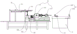
Fig. 1 and 2 are schematic overall structures of the present invention;
FIG. 3 is a front view of the loading device/cutting device/gripping mechanism of the present invention;
FIG. 4 is a top view of the punch/cylindrical tooling of the present invention;
FIG. 5 is a schematic structural view of the automatic material picking device of the present invention;
FIG. 6 is an enlarged schematic view of the structure at A in FIG. 1;
FIG. 7 is a schematic view of the overall structure of the automatic sorting mechanism according to the present invention;
FIG. 8 is a left side view of the automatic sorting mechanism of the present invention;
FIG. 9 is an enlarged view of a part of the structure of the present invention;
FIG. 10 is a block diagram of the control system of the present invention;
fig. 11 is a flowchart of a steel pipe machining control method of the present invention.
In the above figures: 1. a feeding device; 11. a support table; 12. a feeding mechanism; 121. a first feeding guide head; 122. a second feeding guide head; 13. a transfer table;
2. a cutting device; 21. cutting off a main spindle box of the permanent magnet motor; 211. cutting off the auxiliary clamping mechanism; 212. cutting off the permanent magnet motor; 213. cutting off the clamping chuck; 22. a cutter mechanism; 23. an automatic sorting mechanism; 231. a first opening and closing block; 232. a second opening and closing block; 233. a rotating shaft; 234. a groove;
3. a stamping device; 31. a gripping mechanism; 311. a clamping driving cylinder; 312. an up-down moving cylinder; 313. Clamping a finger tool; 314. a clamping cylinder; 32. a stamping feeding mechanism; 321. a station frame; 3211. a first station tank; 3212. a second station groove; 3213. a third station groove; 3214. a fourth station tank; 3215. a fifth station groove; 3216. a sixth station groove; 322. transplanting the assembly; 3221. a transfer rod; 3222. a transplanting groove; 323. stamping the sliding component; 324. a lifting assembly; 325. a scrap iron removing component; 326. a first steel pipe stopper; 327. a second steel pipe stopper; 33. a measuring mechanism; 331. a grating scale; 332. a measuring arm; 34. a stamping and oiling mechanism; 341. a top plate; 342. a nozzle tip; 343. a lifting block; 35. a stamping mechanism; 351. a servo pressure cylinder;
4. a roll material conveying device; 5. an outer circle machining device; 51. an outer circle conveying and positioning mechanism; 511. an excircle transmission positioning rod; 52. a main spindle box of an excircle permanent magnet motor; 521. the outer circle assists the clamping mechanism; 522. an outer circle permanent magnet motor; 523. clamping a chuck by an excircle; 53. a stock stop mechanism; 531. a swing arm; 532. a stopper; 533. a cylinder; 54. an outer circle machining mechanism; 55. a chute; 56. a buffer table; 57. a buffer conveyor;
6. an automatic material picking device; 61. a material picking and conveying mechanism; 611. a conveyor belt; 62. a pushing mechanism; 63. a storage mechanism; 631. a storage buffer; 632. an alignment assembly; 633. a storage tray; 64. a picking mechanism; 641. Picking up the frame; 642. a material grabbing and lifting assembly; 643. moving the gripper; 644. moving and taking the slide rail; 645. a first cylinder; 646. a second cylinder; 647. an optical axis; 648. a rack; 649. carrying vehicle.
Detailed Description
Referring to fig. 1, the embodiment of the invention provides a steel pipe machining integrated device, which comprises a workbench, wherein a cutting device 2, a punching device 3 and an outer circle machining device 5 are sequentially arranged on the workbench; and a feeding device 1 is arranged at one end of the cutting device 2, and an automatic material picking device 6 is arranged at one end of the excircle processing device 5. The steel pipe is conveyed to a cutting device 2 by a feeding device 1 to be cut off and processed into an inner hole, then clamped to a punching device 3 to be punched, then conveyed to an outer circle processing device 5 to be processed into an outer circle, finally conveyed to an automatic material picking device 6 to be sequentially arranged, conveyed into a skip car to be loaded, and the direction from the feeding device 1 to the automatic material picking device 6 is the conveying direction of the steel pipe.
Referring to fig. 2, the feeding device 1 includes a support table 11, a feeding mechanism 12 is mounted on the support table 11, and the feeding mechanism 12 includes a feeding guide head and a transfer table 13, in this embodiment, the feeding guide head includes a first feeding guide head 121 and a second feeding guide head 122, the first feeding guide head 121 is located at one end of the support table 11, and the second feeding guide head 122 is located at the other end of the support table 11; conveying platform 13 is installed on supporting bench 11, and second material loading direction guide head 122 is installed on conveying platform 13, still is equipped with material loading sliding assembly on conveying platform 13, and material loading sliding assembly slides along the direction of transfer, adopts above structure to make conveying platform 13 drive second material loading direction guide head 122 and slide towards cutting device 2, makes the steel pipe can be along with second material loading direction guide head 122 conveying to cutting device 2 automatically from this, carries out next process.
Referring to fig. 3, and fig. 7 and 8, the cutting device 2 includes a cutting permanent magnet motor headstock 21, a cutter mechanism 22, and an automatic sorting mechanism 23; the feeding end of the cutting permanent magnet motor spindle box 21 is arranged opposite to the discharging end of the feeding device 1, and the cutting permanent magnet motor spindle box 21 is arranged opposite to the cutter mechanism 22. Specifically, the cutting permanent magnet motor spindle box 21 is coaxially provided with a cutting auxiliary clamping mechanism 211, a cutting permanent magnet motor spindle box 212 and a cutting clamping chuck 213 along the conveying direction, the cutting permanent magnet motor 212 is located between the cutting auxiliary clamping mechanism 211 and the cutting clamping chuck 213, and the axis of the feeding end of the cutting auxiliary clamping mechanism 211 coincides with the axis of the feeding guide head along the conveying direction. Specifically, the feeding end of the auxiliary cutting-off clamping mechanism 211 is arranged opposite to the discharging end of the second feeding guide head 122, that is, the second feeding guide head 122 conveys the steel pipe to the auxiliary cutting-off clamping mechanism 211, the auxiliary cutting-off clamping mechanism 211 clamps the steel pipe, and then the steel pipe is conveyed to the clamping chuck 213 via the permanent magnet cutting-off motor 212, and then the steel pipe is subjected to flat-end cutting processing via the cutter mechanism 22. Specifically, the cutter mechanism 22 includes a cutter table, a cutter sliding assembly is arranged on the lower end surface of the cutter table, and the cutter table can slide back and forth, left and right along with the cutter sliding assembly; the tool apron is installed on the upper end face of the tool post, a tool bit is installed on the tool apron towards the discharge end of the cutting and clamping chuck 213, and the tool bit and the cutting and clamping chuck 213 are located on the same horizontal plane. After the flat head of the steel pipe is cut, the cutter table slides correspondingly, so that the cutter holder can accurately align to the position, required to be machined, of the steel pipe, and an inner hole is machined in the steel pipe. After the inner hole of the steel pipe is machined, the auxiliary cutting clamping mechanism 211 clamps the steel pipe, and the control system controls the auxiliary cutting clamping mechanism 211 to feed the steel pipe to the cutting clamping collet 213 by a length required actually. And then, the cutter table moves to the corresponding cutting position to cut the steel pipe, and the cutting and blanking process is completed. At this time, the automatic sorting mechanism 23 fixed on the knife stand is in a closed state, and the cut steel pipe falls onto the automatic sorting mechanism 23.
Specifically, the automatic sorting mechanism 23 is an opening and closing member, the opening and closing member includes a first opening and closing block 231 and a second opening and closing block 232 which are independently arranged, the first opening and closing block 231 and the second opening and closing block 232 are arranged in a V shape and are mounted on the knife rest, a rotating shaft 233 is mounted on the lower end face of the first opening and closing block 231, the rotating shaft 233 is fixedly mounted on the knife rest, the first opening and closing block 231 is controlled to rotate by controlling the rotating shaft 233, and the opening and closing operation between the first opening and closing block 231 and the second opening and closing block 232 is achieved. When the size of the cut steel pipe is qualified, the V-shaped opening and closing piece is in a closed state, and the steel pipe falls on the V-shaped opening and closing piece so as to be clamped by the subsequent clamping mechanism 31; when the size of the stub bar or the tailing is cut to be not enough to meet the required size by the flat head of the steel pipe, the V-shaped opening and closing piece is in an open state at the moment, so that the cut stub bar and the cut tailing fall into a slag groove arranged below the automatic sorting mechanism 23. And the upper ends of the first opening and closing block 231 and the second opening and closing block 232 are oppositely provided with a groove 234, and the groove 234 can facilitate the clamping of the steel pipe by the clamping mechanism 31. Structure more than adopting, through material loading unit 1 and cutting device 2 cooperate for the steel pipe can complete automation accomplish cut off and hole processing, and still be equipped with automatic sorting mechanism 23 and material sediment groove among the cutting device 2, make the orderly completion letter sorting of steel pipe in the in-process of processing and the collection of material sediment, and be equipped with the response feedback component on the automatic sorting mechanism 23, make cutting device 2 and stamping device 3 realize continuous harmonious cooperation work.
The stamping device 3 comprises a clamping mechanism 31, a stamping feeding mechanism 32, a measuring mechanism 33, a stamping oiling mechanism 34 and a stamping mechanism 35;
referring to fig. 2 and 3, the gripping mechanism 31 includes a gripping driving cylinder 311, and an up-down moving arm including an up-down moving cylinder 312 and a gripping cylinder 314. The clamping driving cylinder 311 extends to the automatic sorting mechanism 23, the power output end of the clamping driving cylinder 311 is connected with the up-down moving cylinder 312, the power output end of the up-down moving cylinder 312 is connected with the clamping cylinder 314, the end of the clamping cylinder 314 is provided with a clamping finger tool 313, therefore, the clamping driving cylinder 311 pushes the up-down moving cylinder 312 to move back and forth along the extending direction of the clamping driving cylinder 311, the up-down moving cylinder 312 can push the clamping cylinder 314 to move up and down, and then the clamping finger tool 313 clamps the steel pipe under the action of the clamping cylinder 314. Specifically, when equipment detects that there is the steel pipe that has already been processed on the automatic sorting mechanism 23, give punching press information controller with signal transmission, the control is moved the arm from top to bottom and is driven and press from both sides tight finger frock 313 and move towards the direction that is close to automatic sorting mechanism 23, and take away the steel pipe that has already been processed, and place the steel pipe in punching press feeding mechanism 32 department, it makes the steel pipe by cutting device 2 department to stamping device 3 department to press from both sides the mechanism 31 to get through being equipped with, the automatic operation of transporting has been realized, replace manual operation completely, not only practiced thrift the cost but also improved the machining efficiency of steel pipe.
Referring to fig. 4 and 6, specifically, the stamping and feeding mechanism 32 is located on the workbench, in this embodiment, the stamping and feeding mechanism 32 includes six station frames 321, the station frames 321 include a first station frame, a second station frame, a third station frame, a fourth station frame, a fifth station frame, and a sixth station frame, and the station frames 321 are sequentially arranged along the same axis; every station frame 321 all includes two station platforms of arranging along the steel pipe direction of placing, form two rows of station platforms from this, and be equipped with corresponding station groove on the up end of every station platform, first station groove 3211, second station groove 3212, third station groove 3213, fourth station groove 3214, fifth station groove 3215, sixth station groove 3216 promptly, in order to be used for placing the steel pipe, the structure in each station groove cooperatees with the structure of steel pipe, make the steel pipe can be stable place on station frame 321. One side of the station rack 321 is provided with a transplanting assembly 322, and the transplanting assembly 322 extends towards the direction in which the station racks 321 are arranged, namely, extends from the first station rack to the sixth station rack. In this embodiment, the transplanting assembly 322 is formed by two parallel conveying rods 3221, the two conveying rods 3221 are arranged in parallel with the two rows of work racks in a crossing manner, and the conveying rods 3221 are provided with transplanting grooves 3222, each transplanting groove 3222 includes a first transplanting groove, a second transplanting groove, a third transplanting groove, a fourth transplanting groove, a fifth transplanting groove, and a sixth transplanting groove, the steel pipe can be clamped into the transplanting groove 3222, and the transplanting groove 3222 is arranged corresponding to the station groove, so that the transplanting assembly 322 can stably transfer the steel pipe. And the front end and the tail end of the transplanting assembly 322 are respectively provided with a lifting assembly 324 along the conveying direction, and the lifting assembly 324 is positioned below the transplanting assembly 322. Specifically, the lifting assembly 324 comprises an air cylinder and a lifting platform, the lifting platform is connected with the air cylinder, and the lifting platform is in contact with the transplanting assembly 322, so that the lifting platforms at two ends drive the transplanting assembly 322 to move up and down under the action of the air cylinder, meanwhile, the air cylinder fixed on the side edge of the lifting assembly 324 at the other end is installed in parallel with the transplanting assembly 322, the driving end part of the air cylinder is connected with the transmission rod 3221, two sections of stamping sliding assemblies 323 are installed on the lower end face of the transplanting assembly 322, and then the air cylinder can drive the transmission rod to move left and right. Meanwhile, two sections of stamping sliding assemblies 323 are mounted on the lower end face of the transplanting assembly 322, wherein the first section of stamping sliding assembly extends from the first station frame to the second station frame, and the second section of stamping sliding assembly extends from the fifth station frame to the sixth station frame, so that the steel pipes are sequentially conveyed from the first station to the sixth station under the combined action of the stamping sliding assemblies 323 and the lifting assembly 324. Specifically, when the steel pipe is clamped to the first station, the iron scrap removing mechanism located on one side of the first station blows air to the steel pipe to clean iron scraps. After the scrap iron is cleaned, the lifting assembly 324 moves upwards to lift the steel pipe away from the station frame 321, the punching sliding assembly 323 drives the steel pipe to move 300mm to the second station along the conveying direction, then the lifting assembly 324 moves downwards to enable the steel pipe to be located on the second station, then the transplanting assembly 322 resets and moves 300mm to the first station to wait for the next cut steel pipe.
After the steel pipe is moved to the second station, the length measurement is started by the measuring mechanism 33 located at one side of the second station. The measuring arm 332 is provided with a grating ruler 331, one end of the grating ruler 331 is connected with the measuring arm 332, the other end of the grating ruler 331 extends towards the stamping and feeding mechanism 32, the measuring direction of the grating ruler 331 is perpendicular to the extending direction of the stamping and feeding mechanism 32, and the length of the steel pipe is measured. Specifically, be equipped with the cylinder on the measuring arm 332, the direction of motion of cylinder is mutually perpendicular with the extending direction of punching press feeding mechanism 32, moves towards being close to second station department promptly, and the both sides of cylinder are equipped with the optical axis, plays spacing effect to the motion of cylinder from this, prevents that the cylinder motion from deviating, influences measured data, just the end of cylinder is ann has the reading frock, and the reading frock is connected with both sides optical axis simultaneously. Grating scale 331 includes the reading head, and the reading head is connected with the frock of cylinder department, under the effect of cylinder, promotes frock and reading head and moves towards the second station department at steel pipe place, makes the reading head contact with the one end of steel pipe, and with the other end top of steel pipe to second steel pipe stop 327 department alignment, second steel pipe stop 327 is located on the second station frame. After the steel pipes are aligned, the grating ruler 331 and the reading head measure the length. After the measurement is completed, the measuring mechanism 33 is reset, and the length of the next steel pipe is measured. Meanwhile, the transplanting assembly 322 moves the measured steel pipe from the second station to the third station, and then the transplanting assembly 322 is reset.
And after the steel pipe is moved to the third station, the stamping and oiling mechanism 34 positioned on one side of the third station stamps and oils the steel pipe. Specifically, one end on the third station frame is equipped with elevator 343, and elevator 343 contacts with the one end of steel pipe. When the length of the steel pipe is qualified, the lifting block 343 is in a lifting state, the stamping and oiling mechanism 34 at the third station operates, the air cylinder drives the top plate 341 and the oil nozzle 342 to move, the top plate 341 pushes the steel pipe, one end of the steel pipe is pushed against the lifting block 343 to be aligned, and the oil nozzle 342 is oiled. When the length of the steel pipe is unqualified, the lifting block 343 is in a descending state, the stamping and oiling mechanism 34 at the third station operates, the air cylinder drives the top plate 341 and the oil nozzle 342 to move, the steel pipe is pushed by the top plate 341, and under the pushing action of the top plate 341, the steel pipe keeps continuously advancing and then drops into the waste material tank below the station frame 321 due to the fact that the other end of the steel pipe is not blocked by the lifting block 343, so that the product with unqualified length is removed, and the accurate control of the length of the steel pipe is further improved.
The stamping mechanism 35 comprises a pre-stamping part and a stamping part which are sequentially arranged along the extension direction of the transplanting assembly 322, the fourth station frame is aligned with the pre-stamping part, and the fifth station frame is aligned with the stamping part. The steel pipe is transported to the fourth station from the third station by transplanting subassembly 322, and servo pressure cylinder 351 drives the mould and begins the operation, carries out the preliminary punching to the steel pipe, then transports to the fifth station by the fourth station again and carries out the punching press, adopts the sectional type punching press, mainly prevents that a punching press makes the steel pipe atress too big and cause the damage. After the stamping is completed, the steel pipes are sequentially conveyed to a sixth station, namely a buffer position, waiting for the next movement of the transplanting assembly 322, the steel pipes which are stamped in the sixth station are lifted up and conveyed to the rolling material conveying device 4, the rolling material conveying device 4 is positioned at one side of a sixth station frame 321, namely, positioned at the middle position between the sixth station frame and the excircle conveying and positioning mechanism 51, one end of the rolling material conveying device 4 is connected with the excircle processing device 5, and the rolling material conveying device 4 inclines downwards towards the excircle processing device 5, specifically, the rolling material conveying device 4 comprises a bracket and a bearing table, the bearing table is installed on the bracket and is in a downwards inclined state, namely, the plane where the feeding end of the bearing table is positioned is higher than the plane where the discharging end of the bearing table is positioned, so that a downwards inclined table top is formed, and the discharging end of the bearing table is fixedly connected with one end of the excircle processing device 5, so that the transplanting assembly 322 places the steel pipes on the downwards inclined bearing table, and rolling the steel pipe into the cylindrical machining device 5 according to inertia, and conveying the steel pipe into the cylindrical machining device 5. Through the cooperation of transplanting the subassembly 322 and the lifting unit 324 in stamping device 3 for the steel pipe realizes the automation completely at the in-process of different station piece conveying, and the cooperation of measuring mechanism 33 and punching press mechanism 34 among the punching press controlling means for equipment carries out further measurement and gets rid of the further of the unqualified steel pipe of size to the length of steel pipe, has further improved the accuracy of steel pipe size from this, has guaranteed the quality of later stage product. And one end of the cylindrical machining device 5 is also provided with a rolling material conveying device 4, and the steel pipe is rolled into the cylindrical machining device 5 through the stamping device 3 through the rolling material conveying device 4, so that the automatic continuous machining of the steel pipe is realized.
Referring to fig. 2 and 6, the cylindrical machining device 5 is located on one side of the rolling material conveying device 4, a feeding end of the cylindrical machining device 5 is arranged opposite to a discharging end of the rolling material conveying device 4, and a discharging end of the cylindrical machining device 5 is arranged opposite to the automatic material picking device 6. The excircle processing device 5 comprises an excircle transmission positioning mechanism 51, an excircle permanent magnet motor spindle box 52, an excircle processing mechanism 54 and an excircle blanking buffer mechanism, wherein the excircle permanent magnet motor spindle box 52 is positioned between the excircle transmission positioning mechanism 51 and the excircle processing mechanism 54; the excircle blanking buffer mechanism is connected with the excircle processing mechanism 54, the excircle blanking buffer mechanism comprises a chute 55, a buffer table 56 and a buffer conveyor belt 57, one end of the chute 55 is connected with the excircle processing mechanism 54, the other end of the chute is connected with the buffer table 56, the buffer table 56 inclines downwards and is connected with the buffer conveyor belt 57, and the buffer table is connected with the buffer conveyor belt, namely the buffer conveyor table and the buffer conveyor belt are fixedly connected into an integral structure; the buffer conveyor belt is connected with the automatic material picking device. Specifically, the excircle transmission positioning mechanism 51 comprises an excircle transmission positioning rod 511, and the feed end of the excircle transmission positioning mechanism 51 is connected with the discharge end of the roller conveyor 4, so that the steel pipe is rolled to the excircle transmission positioning mechanism 51 by the roller conveyor 4, and then is transmitted to the feed end of the excircle permanent magnet motor spindle box 52 under the action of the excircle transmission positioning rod 511. The excircle permanent magnet motor headstock 52 comprises an excircle permanent magnet motor 522, one end of the excircle permanent magnet motor 522 is connected with an excircle auxiliary clamping mechanism 521, and the other end of the excircle permanent magnet motor 522 is connected with an excircle clamping chuck 523. The upper end surface of the excircle permanent magnet motor 522 is also provided with a material stop mechanism 53, and the material stop mechanism 53 comprises a bracket, a swing arm 531, a stopper 532 and a cylinder 533; the support is fixed in the up end of excircle permanent-magnet machine 522, and the one end and the support of cylinder 533 are rotated and are connected, and the power take off end of cylinder 533 is connected with the one end of swing arm 531, and the other end of swing arm 531 is connected with fender head 532, and the middle part and the support of swing arm 531 rotate to be connected. Stock stop 53 extends to excircle permanent-magnet machine 522's front end along the driven direction of excircle permanent-magnet machine 522, when excircle conveying locating lever 511 conveys the steel pipe to excircle auxiliary clamping mechanism 521, excircle auxiliary clamping mechanism 52 presss from both sides tight steel pipe and sends into in the permanent-magnet machine headstock, convey forward to excircle clamp chuck 523 under excircle permanent-magnet machine 522's the effect, when control system control excircle permanent-magnet machine 522 stall, the steel pipe is because inertia can continue to convey forward, make the length of steel pipe output exceed actually required, stock stop 53 of excircle permanent-magnet machine 522 upper end begins the function under the drive of cylinder 533 this moment, make swing arm 531 drive the stop 532 and keep off the steel pipe in the relevant position that is fit for the excircle processing. Then, the outer circle machining mechanism 54 is used for machining the outer circle of the steel pipe, a slag groove is formed below the outer circle machining mechanism 54, and scrap iron generated by machining the outer circle falls into the slag groove and is discharged. After the steel pipe is processed, the steel pipe rolls onto the buffer table 56 through the sliding groove 55, rolls to the buffer conveyor belt 57 along the buffer table 56, the buffer conveyor belt 57 is provided with a buffer, and when the steel pipe is inclined during rolling down, the buffer is lifted, the steel pipe is blocked, the buffer descends after the steel pipe is buffered and the position of the steel pipe is adjusted, and the steel pipe rolls to the material picking conveying mechanism in the automatic material picking device stably.
Referring to fig. 2 and 5, the automatic pickup device 6 includes a pickup transport mechanism 61, a storage mechanism 63, and a pickup mechanism 64; the material picking and conveying mechanism 61 is connected with the storage mechanism 63, the outer side of the tail end of the material picking and conveying mechanism 61 is provided with a pushing mechanism 62, and the pushing direction of the pushing mechanism 62 is vertical to the conveying direction of the material picking and conveying mechanism 61; one side of the storage mechanism 63 is provided with a bearing vehicle, and the picking mechanism 64 is positioned above the storage mechanism and the bearing vehicle. Specifically, the steel pipe rolls to the material picking and conveying mechanism from the outer circle blanking buffer mechanism stably, the steel pipe slides to the tail end of the conveying belt 611 along the conveying direction, the tail end of the conveying belt 611 is provided with the pushing mechanism 62, the pushing mechanism 62 is located on the outer side of the conveying belt 611, and the pushing direction of the pushing mechanism is perpendicular to the conveying direction of the conveying belt 611. The storage mechanism 63 includes a storage tray which is located inside the conveyor belt 611 and is disposed along the pushing direction of the pushing mechanism 62; when the steel pipe is conveyed to the end of the conveyor belt 611, the pushing mechanism 62 pushes the steel pipe into the storage mechanism 63. The storage mechanism is also provided with a storage buffer part which is mainly used for buffering the steel pipe and righting the moving position direction; meanwhile, one side of the storage mechanism is provided with an alignment assembly, and one end of the steel pipe is mainly pushed to the side edge of the storage mechanism, so that all the steel pipes are aligned and arranged.
The picking mechanism 64 comprises a picking frame 641, a material grabbing lifting assembly 642 and a moving gripper 643, wherein a moving slide rail 644 is arranged at the top of the picking frame 641, the moving slide rail 644 extends from the upper part of the storage mechanism 63 to the upper part of the carrying vehicle 649, the material grabbing lifting assembly 642 is arranged on the moving slide rail 644, a first air cylinder 645 is arranged on the moving slide rail 644, and the power output end of the first air cylinder 645 is connected with the material grabbing lifting assembly 642 and enables the material grabbing lifting assembly 642 to slide back and forth along the extending direction of the moving slide rail under the action of the first air cylinder 645.
Grab material hoist assembly 642 includes second cylinder 646, optical axis 647, rack 648, optical axis 647 is two, and sets up respectively in the both sides of second cylinder 646 for the motion of cylinder is more stable. Meanwhile, the power output end of the second air cylinder 646 is connected with the moving gripper, a magnetic suction cup is arranged on the moving gripper 643, under the pushing action of the second air cylinder, the magnetic suction cup of the moving gripper 643 is tightly attached to the steel pipe and transfers the steel pipe into the bearing vehicle 649, and the second air cylinder 646 can automatically identify the height position and drive the moving gripper 643 to suck the steel pipe and stack the steel pipe into the bearing vehicle 649 layer by layer.
The structure is equipped with excircle blanking buffer gear between excircle processingequipment 5 and automatic material device 6, the steel pipe that makes excircle processing accomplish through excircle blanking buffer gear's connection gets into automatic material device 6 department of picking up by 5 departments of excircle processingequipment automatically, convey through picking up material transport mechanism 61, and the propelling movement of terminal propelling movement mechanism 62 to the steel pipe, make the steel pipe get into storage mechanism 63, at last through picking up mechanism 64 with the steel pipe immigration bear the car in, the automated processing of steel pipe is finally accomplished, the machining efficiency of steel pipe has been improved, the cost is reduced, the occupation of land space has been reduced, the process stock has been avoided, the problem that steel pipe machining efficiency is low among the prior art has been solved.
Referring to fig. 10, the present invention provides a block diagram of a control system for steel pipe machining. The control system comprises a remote control system, an information control system and an MES management system, wherein the information control system and the MES management system are arranged on a workbench, the remote control system comprises a wireless transmitting module, the information control system comprises a wireless receiving module, the remote control system and the information control system are in data communication through a wireless network, and the information control system is electrically connected with the MES management system. The information control system comprises a feeding information controller electrically connected with the feeding device 1, a cutting information controller electrically connected with the cutting device 2, a stamping information controller electrically connected with the stamping device 3, an outer circle machining information controller electrically connected with the outer circle machining device 5 and an automatic material picking information controller electrically connected with the automatic material picking device 6. Specifically, the order information of the remote control system comprises information such as an order number, steel pipe details, cutting length and cutting quantity, the information is transmitted to the information control system through a wireless network, the information control system transmits the received order information to the MES management system, and a worker checks the order information through the MES management system and controls the processing system to work through the MES management system.
According to the steel pipe cutting device, data communication is carried out through a wireless network through a remote control system and an information control system, and the information control system and an MES management system are electrically connected, so that the control of a feeding information controller on the feeding device 1 and the control of a cutting information controller on the cutting device 2 are realized, and the steel pipes can automatically and continuously complete feeding and cutting processes; and the punching device 3 is controlled by the punching information controller through the induction feedback element on the cutting device 2, the steel pipe is transferred to the punching device 3 from the cutting device 2, the punching operation of the steel pipe is completed by the punching information controller, the steel pipe is transferred to the excircle processing device 5, the excircle processing of the steel pipe is completed through the control of the excircle processing information controller, the steel pipe is conveyed to the automatic material picking device 6, the processed steel pipe is orderly stored and transferred through the control of the automatic material picking information controller, thereby the complete automatic continuous processing of the steel pipe is realized through the continuous control of the information controllers on the corresponding devices, the rejection rate is reduced, the processing efficiency of the steel pipe is improved, the cost is reduced, the problem of low processing efficiency of the steel pipe in the prior art is solved, and simultaneously the information control system is butted with an MES management system, the real-time feedback of the parameters in the manufacturing process of the product is realized, and the digitization degree of the equipment is improved.
As shown in fig. 11, an embodiment of the present invention further provides a control method for the above steel pipe machining, which may include:
s1: a user inputs feeding parameters, cutting parameters, stamping parameters, excircle processing parameters and automatic material picking parameters through a remote control system, and the remote control system sends the input parameters to an information control system through a wireless transmitting module;
s2: after the feeding information controller receives the parameter information through the wireless receiving module, the feeding information controller controls the feeding device 1 to convey the steel pipe to the feeding end of the cutting mechanism;
s3: the cutting information controller controls the cutting device 2 to complete the processing and cutting of the inner hole according to the input parameters, the cut steel pipe falls into the automatic sorting mechanism 23 with the V-shaped structure, the cutting information controller feeds back a signal to the remote control system after detecting the steel pipe on the automatic sorting mechanism 23, and then the remote control system sends the signal to the stamping information controller;
s4: after the stamping information controller receives the signal, the clamping mechanism 31 is controlled to clamp the steel pipe to the first station, the material taking time is controlled to be completed within the time of machining an inner hole, then the iron scrap removing mechanism is controlled to complete scrap removing operation, the transplanting assembly 322 is controlled to convey the steel pipe, and meanwhile the stamping information controller sequentially controls the measuring mechanism 33, the stamping oil applying mechanism 34 and the stamping mechanism 35 to sequentially complete the procedures of measuring, stamping oil applying and stamping of the steel pipe; finally, the transplanting assembly 322 conveys the steel pipe to a sixth station, when the transplanting assembly 322 moves next time, the steel pipe at the sixth station is conveyed to the rolling material conveying device 4, and then the steel pipe rolls into the excircle conveying and positioning mechanism 51 from the rolling material conveying device 4;
s5: the excircle processing information controller controls the excircle transmission positioning mechanism 51 to transmit the steel pipe to the excircle permanent magnet motor spindle box 52 and to transmit the steel pipe to a corresponding length, then controls the cutter mechanism to carry out excircle processing, and transmits the processed steel pipe to the material picking and transmitting mechanism 61 through the excircle blanking buffer mechanism;
s6: the automatic material picking information controller controls the material picking transmission mechanism 61 to transmit, when the steel pipe reaches the tail end of the material picking transmission mechanism 61, the automatic material picking information controller controls the pushing mechanism 62 to apply a pushing force perpendicular to the transmission direction to the steel pipe, so that the steel pipe is moved to the storage mechanism 63, the steel pipe storage quantity parameter sent by the remote control system is used, and when the number of the steel pipe reaches an input value, the automatic material picking information controller controls the material picking mechanism 64 to move the stored steel pipe into the bearing vehicle.
According to the control method for processing the steel pipe, the steel pipe can be processed automatically and continuously, namely, the steel pipe can be fed, cut off, processed in an inner hole, punched, processed in an outer circle and automatically stored and picked up, so that the processing efficiency of the steel pipe is improved, the cost is reduced, and the problem of low processing efficiency of the steel pipe in the prior art is solved.
For a more clear explanation of the present application, the working principle and method of the present invention will be further explained by taking the embodiments shown in fig. 1 to 11 as examples:
(1) feeding process
The original steel pipe is put into the feeding guide head of the feeding mechanism 12, and the conveying table 13 drives the second feeding guide head 122 to slide towards the cutting device 2, so that the steel pipe is conveyed to the cutting device 2 along with the feeding guide head to perform the next process.
(2) Cutting/inner hole/grabbing process
After the original steel pipe is sent to the auxiliary cutting clamping mechanism 211 by the second feeding guide head 122, the auxiliary cutting clamping mechanism 211 clamps the original steel pipe, the original steel pipe is sent to the cutting clamping chuck 213 by the cutting permanent magnet motor 212, the cutting information controller firstly controls the cutter mechanism 22 to move to cut the flat head of the original steel pipe, and meanwhile, the automatic sorting mechanism 23 is controlled by the cutting information controller to be in an open state, so that the cut material head falls into a slag groove below the automatic sorting mechanism 23 and is discharged; and when the length of the tail of the steel pipe is less than the required length, the automatic sorting mechanism 23 is also in an open state at the moment, and the tail falls into a slag chute below the automatic sorting mechanism 23 to be discharged.
After the original steel pipe is flatheaded, the cutter mechanism 22 moves to an inner hole turning working position to machine an inner hole of the steel pipe, the automatic sorting mechanism 23 fixed on the cutter table is in a closed state at the moment, after the inner hole machining is finished, the cutting auxiliary clamping mechanism 211 clamps the steel pipe and conveys the steel pipe with the corresponding length to the cutting clamping chuck 213, the length is consistent with the cutting length parameter input in the remote control system, namely the remote control system sends the cutting length information of the steel pipe to the cutting information control system, and the cutting information control system controls the cutting permanent magnet motor 212 to convey the corresponding length of the original steel pipe to the cutting clamping chuck 213 after receiving the information.
After the steel pipe is conveyed to the corresponding length, the cutter table moves to a cutting working position, and the steel pipe is subjected to cutting and blanking procedures. The automatic sorting mechanism 23 of the V-shaped structure fixed on the knife rest moves simultaneously along with the knife rest, and the automatic sorting mechanism 23 is in a closing state at the moment, so that the cut steel pipes fall onto the automatic sorting mechanism 23 of the V-shaped material head and the material tail.
After the blanking is completed, the cutter mechanism 22 moves to the inner hole turning working position, and the inner hole turning process is performed on the next steel pipe. Meanwhile, the equipment detects the machined steel pipes on the automatic sorting mechanism 23, sends signals to the stamping information controller, the stamping information controller controls the clamping mechanism 31 to move, the machined steel pipes on the automatic sorting mechanism 23 are grabbed away while the second steel pipe inner holes are machined, and material taking is ensured to be completed within the time of machining the inner holes.
After the inner hole of the second steel pipe is turned, the tool post moves to a cutting working position to perform a cutting process, the auxiliary cutting clamping mechanism 211 clamps the steel pipe, and the steel pipe with the corresponding size input on the remote control system is repeatedly conveyed to the cutting clamping chuck 213. The second machined steel tube falls onto the closed automatic sorting mechanism 23, and then the inner hole turning and material grabbing processes are repeated in a circulating mode.
(3) Scrap iron removing process
The clamping mechanism 31 takes materials and puts the materials into a first station of the stamping and feeding mechanism 32, and then the iron scrap removing mechanism is controlled to blow air to clean iron scraps.
(4) Length measurement/defective product removal/oiling process
After the iron fillings clearance finishes, punching press information controller received signal, transplants subassembly 322 and operates, lifts up the back with the steel pipe of first station, lateral shifting 300mm to second station, the position of second station for measuring steel pipe length, the steel pipe is placed behind the second station, transplants subassembly 322 and resets to 300mm of lateral shifting to opposite direction, waits for the next steel pipe that cuts off.
After the steel pipe moves to the second station, the stamping information controller controls the grating ruler 331 length measuring mechanism to start length measurement, the air cylinder 533 pushes the movable reading head to move, one side of the steel pipe is pushed to the second steel pipe baffle tool to be aligned, then length measurement is carried out, and the measuring process is also ensured to be completed within the process time of machining the inner hole. After measurement, the reading head tool of the grating ruler 331 is reset to wait for the next steel pipe to measure the length. Specifically, the processes of cutting/inner hole, grabbing, removing scrap iron and feeding the transplanting assembly 322 are sequentially and circularly operated, the transplanting assembly 322 moves the second steel pipe to the second station for length measurement, and simultaneously moves the first steel pipe with measured length to the third station, and the grating ruler 331 measures the size of the second steel pipe on the second station.
The steel pipe is sent to third station department, and when the steel pipe length measurement was qualified, the elevator 343 of third station department was the rising state, and the punching press end mechanism of buying oil of third station department operates, and cylinder 533 drives roof 341 and glib talker 342 frock removal, and the steel pipe top aligns to elevator 343 department, and the buying oil is carried out. When the steel pipe is unqualified in measurement, the lifting block 343 is the decline state, and when the stamping end mechanism of buying oil of third station department operated, cylinder 533 drove roof 341 glib talker 342 frock and removes, and the steel pipe continues to keep advancing under the operation of stamping mechanism 34 of buying oil, because there is not the lifting block to block, then drops in the dirty silo, has realized the accurate control of steel pipe length from this.
(5) Punching step
When the above processes are operated circularly, the steel pipe is moved from the third station to the fourth station pre-stamping position in sequence, the servo pressure cylinder 351 starts to operate, the steel pipe is pre-stamped, and then the steel pipe is transported from the fourth station to the fifth station for stamping. After the punching is completed, the steel pipes are sequentially conveyed to a sixth station, namely a buffer position, the next movement of the transplanting assembly 322 is waited, and the transplanting assembly 322 conveys the punched steel pipes on the sixth station to the rolling material conveying device 4.
(6) Outer circle procedure
Along with the cyclic operation of the transplanting assembly 322, the punched steel pipe rolls down to the position of the excircle servo feeding transmission rod along the rolling material conveying device 4, the excircle processing information controller controls the excircle conveying positioning rod 511 to operate, the steel pipe is fed into the excircle auxiliary clamping mechanism 521 and is conveyed forwards to the excircle clamping chuck 523 under the action of the excircle permanent magnet motor 522. At this time, the material stop mechanism 53 operates, the air cylinder 533 pushes the swing arm 531 to move, and the swing arm 531 drives the stopper 532 to stop the steel pipe at a size position suitable for excircle processing. The outer circle machining mechanism 54 operates to perform outer circle machining, and scrap iron is discharged along the material slag groove.
(7) Automatic material picking process
After the steel pipe is processed, the steel pipe rolls into the buffer table 56 through the sliding groove 55, falls to the buffer conveyor belt 57 along the buffer table 56, and is inclined due to the fact that the steel pipe rolls downwards, the buffer part is lifted at the moment, the steel pipe is blocked, the steel pipe is guaranteed to be buffered and is guaranteed to be in a position righting state, the buffer part descends, and the steel pipe stably rolls into the buffer conveyor belt and is conveyed to the material picking conveying mechanism.
When the steel pipe is conveyed to the tail end of the material picking conveying mechanism 61, the pushing mechanism 62 senses the steel pipe, pushes the steel pipe into the storage mechanism 63, rolls along the downward inclined slope of the storage mechanism 63, rises the storage buffer at the moment, buffers the steel pipe, and positions and directions of the steel pipe are aligned, then the storage buffer descends, and the steel pipe continues to move and is sequentially and stably arranged in the tray of the storage mechanism 63.
When the number of steel tubes sequentially arranged in the trays of the storage mechanism 63 reaches the number set in the controller, one end of the steel tube is pushed to the side of the storage tray by the liftout aligning assembly 632 to ensure that all the steel tubes are aligned and arranged, and at this time, the picking mechanism 64 above the storage tray starts to operate. The air cylinder on the grabbing lifting assembly 642 is driven by the sensor in the air cylinder to move the magnetic sucker of the grabbing hand 643 to descend to an induction position, and the air cylinder is in close contact with the steel pipe, stops for a period of time, is electrified by magnetic force to be opened, and ensures that the steel pipe is tightly attached to the magnetic sucker. After the magnetic suction cups of the moving grippers 643 suck all steel pipes, the air cylinders on the material grabbing lifting assemblies 642 drive the magnetic suction cups of the moving grippers to rise to a certain position, the first air cylinders 645 arranged on the moving slide rails 644 start to operate to drive the material grabbing lifting assemblies 642, the moving grippers 643 are driven to move to the upper portion inside the bearing vehicle, the second air cylinders 646 on the material grabbing lifting assemblies 642 start to operate, the air cylinders drive the magnetic suction cups of the moving grippers 643 to descend to the inner portion of the bearing vehicle under the action of the sensors in the air cylinders, the steel pipes are stably placed in the bearing vehicle, the magnetic suction cups are powered off, and the steel pipes are orderly arranged and left in the bearing vehicle.
Then, the air cylinder of the material grabbing and lifting assembly 642 starts to operate, and after the magnetic suction cup of the moving gripper 643 is driven to rise to a certain position, the material grabbing and lifting assembly 642 and the moving gripper 643 are reset to the upper side of the storage mechanism 63 along the moving slide rail 644 to wait for the next round of steel pipe alignment, and the operation is repeated. The moving gripper 643 senses the falling position according to the cylinder sensor, and the magnetic sucker is ensured to accurately suck the steel pipe; meanwhile, the steel pipes in the bearing vehicle are orderly stacked layer by layer.
The present invention has been described in detail above with reference to exemplary embodiments. It should be understood, however, that elements, structures and features of one embodiment may be beneficially incorporated in other embodiments without further recitation.
In the description of the present invention, it should be noted that the terms "inside", "outside", "upper", "lower", "front", "rear", "first", "second", etc. indicate orientations or positional relationships based on the positional relationships shown in the drawings, and are only for convenience of description and simplicity of description, but do not indicate or imply that the devices or elements referred to must have a specific orientation, be constructed in a specific orientation, and be operated, and thus, should not be construed as limiting the present invention.
In the description of the present application, the terms "mounted," "connected," "fixed," and the like are used in a broad sense, and for example, "connected" may be a fixed connection, a detachable connection, or an integral connection; either directly or through an intermediary profile. The specific meaning of the above terms in the present application can be understood by those of ordinary skill in the art as appropriate.
Claims (12)
1. The steel pipe machining integrated equipment is characterized by comprising a control system and a workbench, wherein a cutting device, a punching device and an excircle machining device are sequentially arranged on the workbench; a feeding device is arranged at one end of the cutting device, and an automatic material picking device is arranged at one end of the outer circle machining device;
the control system is respectively and electrically connected with the feeding device, the cutting device, the punching device, the outer circle processing device and the automatic material picking device;
the stamping device comprises a stamping feeding mechanism, and the stamping feeding mechanism extends towards the outer circle machining device; a clamping mechanism is arranged above the stamping and feeding mechanism and can slide to the cutting device; one side of punching press feeding mechanism is equipped with measuring mechanism, measuring mechanism includes the measurement arm, install the grating chi on the measurement arm, the one end of grating chi is connected with the measurement arm, and its other end extends towards punching press feeding mechanism department, just the measurement direction of grating chi with punching press feeding mechanism's extending direction is mutually perpendicular to the realization is to the measurement of steel pipe length.
2. The steel pipe processing integrated equipment according to claim 1, wherein the cutting device comprises a cutter mechanism, an automatic sorting mechanism; the automatic sorting mechanism is arranged on a cutter table in the cutter mechanism; the automatic sorting mechanism comprises an opening and closing piece, the opening and closing piece comprises a first opening and closing piece and a second opening and closing piece which are independently arranged, the first opening and closing piece and the second opening and closing piece are arranged in a V shape and are arranged on the cutter platform, a rotating shaft is arranged on the lower end face of the first opening and closing piece, and the rotating shaft is fixedly arranged on the cutter platform.
3. The integrated steel pipe machining device according to claim 2, wherein the clamping mechanism comprises a clamping driving member and a moving arm, the clamping driving member extends towards the automatic sorting mechanism, the moving arm is arranged at a power output end of the clamping driving member, a clamping finger tool is arranged at an end of the moving arm, and the structure of the clamping finger tool is matched with that of the steel pipe.
4. The integrated steel tube machining device according to claim 1, wherein the stamping and feeding mechanism is located on the workbench and comprises a plurality of station frames, and the station frames are sequentially arranged along the same axis; the automatic transplanting device is characterized in that a transplanting assembly is arranged on one side of the station frame, the transplanting assembly extends towards the arrangement direction of the station frame, a stamping sliding assembly is arranged on the lower end face of the transplanting assembly, lifting assemblies are respectively arranged at two end parts of the transplanting assembly along the conveying direction, and the lifting assemblies are located below the transplanting assembly.
5. The integrated steel pipe machining equipment according to claim 4, wherein six station frames are arranged, namely a first station frame, a second station frame, a third station frame, a fourth station frame, a fifth station frame and a sixth station frame which are sequentially arranged in sequence; the stamping sliding assembly comprises a first section of stamping sliding assembly and a second section of stamping sliding assembly, the first section of stamping sliding assembly is extended to the second station frame by the first station frame, and the second section of stamping sliding assembly is extended to the sixth station frame by the fifth station frame.
6. The integrated steel pipe machining device according to claim 5, wherein the stamping device further comprises a stamping and oiling mechanism, the stamping and oiling mechanism is located on one side of the stamping and feeding mechanism and is right opposite to one side of the third station frame, a lifting block is arranged on the other side of the third station frame, and the lifting block is mounted on the side end face of the third station frame.
7. The steel pipe machining integrated equipment according to any one of claims 4 to 6, wherein the outer circle machining device comprises an outer circle conveying and positioning mechanism, an outer circle permanent magnet motor spindle box, an outer circle machining mechanism and an outer circle blanking buffering mechanism, and the outer circle permanent magnet motor spindle box is positioned between the outer circle conveying and positioning mechanism and the outer circle machining mechanism; excircle blanking buffer gear meets with excircle processing agency, excircle blanking buffer gear includes spout, cushion table, buffering conveyer belt, the one end and the excircle processing agency of spout meet, its other end with the cushion table meets, the cushion table downward sloping meets with buffering conveyer belt, buffering conveyer belt with automatic material device of picking up meets.
8. The steel pipe processing integrated equipment according to claim 1, wherein the automatic material picking device comprises a material picking and conveying mechanism, a storage mechanism and a material picking mechanism; the material picking and conveying mechanism is connected with the storage mechanism, a pushing mechanism is arranged on the outer side of the tail end of the material picking and conveying mechanism, and the pushing direction of the pushing mechanism is perpendicular to the conveying direction of the material picking and conveying mechanism; one side of the storage mechanism is provided with a bearing vehicle, and the picking mechanism is positioned above the storage mechanism and the bearing vehicle.
9. The steel pipe machining integrated equipment according to claim 8, wherein the picking mechanism comprises a picking frame and a moving gripper, the picking frame is provided with a moving slide rail, the moving slide rail extends from the upper part of the storage mechanism to the upper part of the bearing vehicle, the moving slide rail is provided with a material grabbing lifting assembly, the material grabbing lifting assembly can slide back and forth along the extending direction of the moving slide rail, the material grabbing lifting assembly is provided with a power source, the power output end of the power source is connected with the moving gripper, the moving gripper is provided with a magnetic sucker, and the moving gripper can move towards the direction of the storage mechanism and the direction of the bearing vehicle.
10. A control system is suitable for the steel pipe machining integrated equipment as claimed in any one of claims 1 to 9, and is characterized by comprising a remote control system, an information control system and an MES management system, wherein the information control system and the MES management system are arranged on a workbench, the remote control system comprises a wireless transmitting module, the information control system comprises a wireless receiving module, the remote control system and the information control system are in data communication through a wireless network, the information control system is electrically connected with the MES management system, and the MES management system is electrically connected with a feeding device, a cutting device, a stamping device, an outer circle machining device and an automatic material picking device respectively.
11. The control system according to claim 10, wherein the information control system comprises a feeding information controller electrically connected to the feeding device, a cutting information controller electrically connected to the cutting device, a punching information controller electrically connected to the punching device, an outer circle processing information controller electrically connected to the outer circle processing device, and an automatic material picking information controller electrically connected to the automatic material picking device.
12. A steel pipe working control method applied to the steel pipe working control system according to claim 11, characterized by comprising the steps of:
a user inputs feeding parameters, cutting parameters, stamping parameters, excircle processing parameters and automatic material picking parameters through a remote control system, and the remote control system sends the input parameters to an information control system through a wireless transmitting module;
after the feeding information processor receives the parameter information through the wireless receiving module, the feeding information processor controls the feeding device to convey the steel pipe to the feeding end of the cutting mechanism;
the cutting information controller controls the cutting device to complete machining and cutting of an inner hole according to input parameters, the cut steel pipe falls into the automatic sorting mechanism with the V-shaped structure, the cutting information controller feeds back signals to the remote control system after detecting the steel pipe on the automatic sorting mechanism, and then the remote control system sends the signals to the stamping information controller;
after the stamping information controller receives the signal, the clamping mechanism is controlled to clamp the steel pipe to the first station, the material taking time is controlled to be completed within the time of machining an inner hole, then the iron scrap removing mechanism is controlled to complete scrap removing operation, the transplanting assembly is controlled to convey the steel pipe, and meanwhile the stamping information controller sequentially controls the measuring mechanism, the stamping oil pumping mechanism and the stamping mechanism to complete the procedures of measuring, stamping oil pumping and stamping of the steel pipe; finally, the steel pipe is conveyed to a sixth station by the transplanting assembly, when the transplanting assembly moves next time, the steel pipe at the sixth station is conveyed to the rolling material conveying device, and then the steel pipe rolls into the excircle conveying and positioning mechanism by the rolling material conveying device;
the excircle processing information controller controls the excircle transmission positioning mechanism to transmit the steel pipe to the excircle processing mechanism through the excircle permanent magnet motor spindle box, controls the cutter mechanism to process the excircle, and transmits the processed steel pipe to the material picking transmission mechanism through the excircle blanking buffer mechanism;
the automatic material picking information controller controls the material picking and conveying mechanism to convey, when the steel pipes reach the tail end of the material picking and conveying mechanism, the automatic material picking information controller controls the pushing mechanism to apply pushing force perpendicular to the conveying direction to the steel pipes, the steel pipes are moved to the storage mechanism, the steel pipes are stored according to the steel pipe storage quantity parameters sent by the remote control system, and when the number of the steel pipes reaches an input value, the automatic material picking information controller controls the material picking mechanism to move the stored steel pipes to the bearing vehicle.
Priority Applications (1)
| Application Number | Priority Date | Filing Date | Title |
|---|---|---|---|
| CN201911344205.0A CN110961935A (en) | 2019-12-24 | 2019-12-24 | Steel pipe machining integrated equipment, control system and control method |
Applications Claiming Priority (1)
| Application Number | Priority Date | Filing Date | Title |
|---|---|---|---|
| CN201911344205.0A CN110961935A (en) | 2019-12-24 | 2019-12-24 | Steel pipe machining integrated equipment, control system and control method |
Publications (1)
| Publication Number | Publication Date |
|---|---|
| CN110961935A true CN110961935A (en) | 2020-04-07 |
Family
ID=70036283
Family Applications (1)
| Application Number | Title | Priority Date | Filing Date |
|---|---|---|---|
| CN201911344205.0A Pending CN110961935A (en) | 2019-12-24 | 2019-12-24 | Steel pipe machining integrated equipment, control system and control method |
Country Status (1)
| Country | Link |
|---|---|
| CN (1) | CN110961935A (en) |
Cited By (4)
| Publication number | Priority date | Publication date | Assignee | Title |
|---|---|---|---|---|
| CN112247596A (en) * | 2020-10-22 | 2021-01-22 | 广州文冲船厂有限责任公司 | Pipe flange production line communication system |
| CN113182860A (en) * | 2021-04-14 | 2021-07-30 | 上海运城制版有限公司 | Automatic control method and system for steel pipe stock house unit |
| CN114227384A (en) * | 2022-01-07 | 2022-03-25 | 青岛张氏机械有限公司 | Intelligent steel pipe machining equipment |
| CN117102891A (en) * | 2023-10-24 | 2023-11-24 | 江苏常达金联汽车科技发展有限公司 | Full-automatic valve guide pipe assembly detecting system |
-
2019
- 2019-12-24 CN CN201911344205.0A patent/CN110961935A/en active Pending
Cited By (6)
| Publication number | Priority date | Publication date | Assignee | Title |
|---|---|---|---|---|
| CN112247596A (en) * | 2020-10-22 | 2021-01-22 | 广州文冲船厂有限责任公司 | Pipe flange production line communication system |
| CN113182860A (en) * | 2021-04-14 | 2021-07-30 | 上海运城制版有限公司 | Automatic control method and system for steel pipe stock house unit |
| CN114227384A (en) * | 2022-01-07 | 2022-03-25 | 青岛张氏机械有限公司 | Intelligent steel pipe machining equipment |
| CN114227384B (en) * | 2022-01-07 | 2023-03-07 | 青岛张氏机械有限公司 | Intelligent steel pipe machining equipment |
| CN117102891A (en) * | 2023-10-24 | 2023-11-24 | 江苏常达金联汽车科技发展有限公司 | Full-automatic valve guide pipe assembly detecting system |
| CN117102891B (en) * | 2023-10-24 | 2024-01-23 | 江苏常达金联汽车科技发展有限公司 | Full-automatic valve guide pipe assembly detecting system |
Similar Documents
| Publication | Publication Date | Title |
|---|---|---|
| CN110961935A (en) | Steel pipe machining integrated equipment, control system and control method | |
| CN211438947U (en) | Integrative equipment of steel pipe processing | |
| CN210549485U (en) | Automatic cutting and welding equipment for integrated plates | |
| CN111408953B (en) | Material handle clearing device and engine cylinder block production line | |
| CN209998588U (en) | touch screen cell-phone polaroid laser cutting automatic feeding discharge apparatus | |
| JPH0773765B2 (en) | Multi-collecting small product sorting / collecting device | |
| CN115415430A (en) | Sheet metal part automatic production system and production process | |
| CN113426909B (en) | Material feeding unit and automated production line | |
| CN210305424U (en) | Automatic punching press assembly line | |
| CN212823876U (en) | Sheet metal production system | |
| CN110722039A (en) | Automatic workpiece stamping carrying and film laminating system | |
| CN116037766A (en) | Automatic production line for stamping, shearing and folding metal plates | |
| CN114227384B (en) | Intelligent steel pipe machining equipment | |
| CN215905365U (en) | Automatic workpiece feeding device | |
| CN213034792U (en) | Numerical control drilling device with automatic feeding and discharging structure | |
| CN211890021U (en) | Screw tap machining device | |
| CN209919423U (en) | Feeding device for numerical control machine tool | |
| CN109158885B (en) | Forming machine capable of automatically feeding filter shell | |
| CN219216763U (en) | Conveying system applied to cover plate glass production | |
| CN220160594U (en) | Part sorting system | |
| JP2549830B2 (en) | Punch press | |
| CN219791702U (en) | Battery cell robot carrying system | |
| CN219486168U (en) | Engraving and milling production line | |
| CN217626387U (en) | Automatic separating and feeding device for steaming tray | |
| CN219254921U (en) | Feeding machine for engraving and milling machine |
Legal Events
| Date | Code | Title | Description |
|---|---|---|---|
| PB01 | Publication | ||
| PB01 | Publication | ||
| SE01 | Entry into force of request for substantive examination | ||
| SE01 | Entry into force of request for substantive examination |