CN1109599A - DC current sensor - Google Patents
DC current sensor Download PDFInfo
- Publication number
- CN1109599A CN1109599A CN94117624A CN94117624A CN1109599A CN 1109599 A CN1109599 A CN 1109599A CN 94117624 A CN94117624 A CN 94117624A CN 94117624 A CN94117624 A CN 94117624A CN 1109599 A CN1109599 A CN 1109599A
- Authority
- CN
- China
- Prior art keywords
- iron core
- current
- coil
- current sensor
- magnetic
- Prior art date
- Legal status (The legal status is an assumption and is not a legal conclusion. Google has not performed a legal analysis and makes no representation as to the accuracy of the status listed.)
- Pending
Links
Images


Classifications
-
- G—PHYSICS
- G01—MEASURING; TESTING
- G01R—MEASURING ELECTRIC VARIABLES; MEASURING MAGNETIC VARIABLES
- G01R29/00—Arrangements for measuring or indicating electric quantities not covered by groups G01R19/00 - G01R27/00
-
- G—PHYSICS
- G01—MEASURING; TESTING
- G01R—MEASURING ELECTRIC VARIABLES; MEASURING MAGNETIC VARIABLES
- G01R19/00—Arrangements for measuring currents or voltages or for indicating presence or sign thereof
- G01R19/18—Arrangements for measuring currents or voltages or for indicating presence or sign thereof using conversion of DC into AC, e.g. with choppers
- G01R19/20—Arrangements for measuring currents or voltages or for indicating presence or sign thereof using conversion of DC into AC, e.g. with choppers using transductors, i.e. a magnetic core transducer the saturation of which is cyclically reversed by an AC source on the secondary side
Abstract
It is an object of the present invention to provide a sensitive DC current sensor, which has a relatively simple construction and a detecting capability with a good linearity, against current variations in a wide range from a microscopic current to a relatively large current (e.g. about 0.2 A to 20 A). In the configuration, wherein an exciting coil and a detecting coil are wound in a toroidal shape around a core consisting of an annular soft magnetic material, when a triangular waveform exciting current which produces a magnetic field exceeding a coercive force of the core is applied to the exciting coil, a direction of the magnetic flux in the core is inverted, whereby an absolute value and a direction of a DC current flowing through a lead wire being detected can be detected, by detecting an inverse timing by a pulse voltage produced in the detection coil for comparison measurement of the pulse intervals.
Description
The present invention relates to DC current sensor, it is applied in the extensive fields, for example, at maintenance switch plate control circuit signal current instruments, various sensor simulate amount current signals from the main equipment that is installed in steel rolling mill's one class, and on the measurement current instrument of control small-sized DC equipment.More particularly, it relates to sensitive DC current sensor, and its structure is simple relatively, from minimum electric current to big relatively electric current (for example approximately 0.2A to 20A) on a large scale in good linearity test ability is all arranged.
In recent years, the equipment of application DC current sensor increased in many technical fields.For these device securities are moved reposefully, the DC current instrument is indispensable, and sensitive DC current sensor is in demand.For this class DC current sensor, that has known has a Hall device method, and magnetrol method and many oscillators of magnetic method (Japanese patent application Nos.Sho471644, Sho53-31176, Sho59-46859).
The formation of Hall device method is such, and detected lead directly circularizes around the iron core outside of being made by soft magnetic material, and Hall device partly is distributed on the iron core, and this iron core has an air gap.Because the DC current of passing through on the detected lead changes, the iron core magnetic linkage variation that is caused is directly detected by Hall device.
Magnetrol method and many oscillators of magnetic method are the iron cores that utilizes by soft magnetic material system, with magnetic test coil coiled annular on iron core, detected lead passes iron core, in advance alternating current is added in the coil on the iron core, the alternation magnetic linkage that is produced reaches full and closes, DC current is by detected lead, making has the direct current magnetic deflection on the full soft magnetic material system iron core that closes in magnetic linkage density (BS) scope, the a certain moment has produced the imbalance of positive and negative direction, and magnetic test coil detects this variation.
For the magnetrol method, because producing magnetic linkage in advance in iron core changes, its formation is a magnetizing coil to be arranged around iron core, the alternating current of determining amount is passed through coil, but, for many oscillators of magnetic method, its formation is owing to produce self-oscillation with the operation of semiconductor ex hoc genus anne in the loop that magnetic test coil links to each other, and vibration makes the duty ratio variation of waveform to the response of sensed current.
Though it is simple relatively on the Hall device method structure, deal with easily, because its detectability does not have the characteristic that depends on Hall device with fixed attention, when adopting existing Hall device, be difficult to have relative high precision (being approximately 20%) when measuring 20A with following electric current, therefore, it is confined to detect big electric current (promptly being higher than 20A).
For example, though may use Hall device, by amplifier amplification detection signal, but, the biasing output that the iron core coercive force of composition DC current sensor is caused and all very big by the drift that temperature characterisitic caused of Hall device, for total energy realizes desired high measurement accuracy, must constantly adjust zero point, consequently precision is low especially.
In addition, though also can consider detected lead is twined hundreds of to several thousand circles or more on the iron core of forming DC current sensor,, this just makes DC current sensor become bigger, thereby has limited its use widely.
At present, though compare with the Hall device method, can measure relative little electric current with the magnetrol method with many oscillators of magnetic method, but its structure but becomes complicated, and, as previously mentioned, need a direct current magnetic deflection, so that when DC current flows through detected lead, the soft magnetic material system of making iron core is full to be incorporated into being in close proximity to and fullly to close magnetic linkage density (BS), and therefore, detected lead must twine tens to hundreds of circle or more on iron core, detect electric current with response, limited its use widely.
In addition,, make that linearity is very poor, can not realize desired high measurement accuracy because the distinctive magnetic characteristic of iron core itself appears in the output characteristics.
As mentioned above, it is hard to tell existing traditional Hall device method, the structure of magnetrol method and many oscillators of magnetic method can cooperate electric current filling (for example approximately 0.2A to 20A) variation on a large scale to relative big electricity from little electric current, at present, in fact they can not be used as sensitive DC current sensor.
The DC current sensor that the purpose of this invention is to provide a kind of sensitivity, it can address the above problem, structure is relatively simple, when electric current from Weak current to big relatively electric current (for example approximately 0.2A to 20A) on a large scale in during variation, detection has good linearity.
The result of the various researchs of being done is the simplest a kind of structures in order to achieve the above object, magnetizing coil and magnetic test coil are wound in annular around the iron core by annular soft magnetic material system, the fact of being seen is, on magnetizing coil, add the triangular wave exciting curent, when the magnetic field that is produced surpasses the coercive force of iron core, the direction of magnetic linkage is just reverse in the iron core, the inventor finds, by detecting in the pulse voltage that magnetic test coil produced that is used for comparing and measuring the recurrent interval, detect reversed time, can detect the DC current absolute value that flows through in the detected lead.
The objective of the invention is to DC current sensor, it is developed according to above-mentioned discovery, comprising: by the iron core that annular soft magnetic material is formed, pass therethrough detected lead, being used for not, the DC current of contact detection flows through from lead; Around iron core, be wound in the magnetizing coil and the magnetic test coil of annular; On magnetizing coil, add the triangular waveform exciting curent, the magnetic field that it is produced in iron core has surpassed the coercive force of iron core, by detecting the pulse voltage that in comparing and measuring the magnetic test coil in recurrent interval, is produced, just the reversed time of iron core magnetic linkage direction can be detected, thereby the DC current absolute value that flows through in the detected conductor can be detected.
DC current sensor structure of the present invention is relatively simple, because it has adopted the simplest structure as basic structure, wherein, magnetizing coil and magnetic test coil are wound in annular around the iron core by annular soft magnetic material system.In addition, on magnetizing coil, add a triangular wave exciting curent, it is excitatory to iron core, the magnetic field that is produced has surpassed the coercive force of iron core, and by detecting in the pulse voltage that magnetic test coil produced that is used for comparing and measuring the recurrent interval, detect the reversed time of iron core magnetic linkage direction, thereby detect absolute value and the direction that flows through DC current in the detected coil.Circuit is very complicated, can from little electric current to big relatively electric current (promptly about 0.2A is to 20A) on a large scale in obtain the very detectability of linearity, thereby it can be used as sensor, is used in the control and maintenance of various DC equipment.
Particularly adopted iron core along the circumferential direction to be divided at least one section structure, made it be easy to be installed on the detected lead, therefore, this DC current sensor can be applied even more extensively.
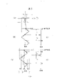
Fig. 1 is the principle synoptic diagram of an embodiment of DC current sensor of the present invention.
Fig. 2 (A is to D) be in the circuit shown in Figure 1 A to D place electric signal waveform key diagram.
Fig. 3 (A is to E) is the conceptual illustration figure of DC current sensor operation logic shown in Figure 1.
Fig. 4 (A) is the illustrated planar figure of another embodiment of DC current sensor of the present invention, (B) is its explanation front view.
The rectilinear figure of Fig. 5 is represented by the relation between the DC current sensor output of the present invention among the DC current of detected lead and Fig. 1.
The rectilinear figure of Fig. 6 is represented by the relation between the DC current sensor output of the present invention among the DC current of detected lead and Fig. 1.
Next, the operation of specific explanations DC current sensor of the present invention with reference to the accompanying drawings.
Fig. 1 is the principle synoptic diagram of an embodiment of DC current sensor of the present invention, wherein, and the main body of numeral 1 expression DC current sensor.
In Fig. 1, the iron core that the annular soft magnetic material of numeral 11 expressions is formed wherein passes detected lead 12, and the DC current of non-contact detecting flows through from this lead.The soft magnetic material of known permalloy or similar material formation is struck out annular, after predetermined Temperature Treatment, build up multilayer tablet, be placed in the insulating resin shell, just form iron core 11.
In Fig. 1, numeral 13 expression magnetizing coils, it is the coiled annular around iron core 11.Numeral 14 expression magnetic test coils, it and magnetizing coil 13 the same ground, coiled annular around iron core 11.
In Fig. 1, the power unit that numeral 2 expressions link to each other with magnetizing coil 13.Power supply 2 is made up of function generator 21 and steady current amplifier 22, applies to give to decide the triangular waveform exciting curent, will describe later on.The circuit part that numeral 3 expressions link to each other with magnetic test coil 14, the giving of pulse voltage correspondence that here obtains being detected by magnetic test coil 14 decided analog quantity output, will describe later on.
In the figure, when the magnetic characteristic of iron core 11 is shown in Fig. 3 (A), add the exciting curent i of a triangular waveform on magnetizing coil 13, the magnetic field that it produced has surpassed the coercive force of iron core 11.In other words, when current peak be i
p, when the coercive force of iron core 11 is Hc, the peak value i of triangular wave exciting curent
pJust determine, so as to have Hc<<Ni
p/ l.
Here, N represents the number of turns of magnetizing coil 13, and l represents the length of magnetic path of iron core 11.Because exciting curent causes magnetic field H in the field core 11 over time shown in Fig. 3 (B).
Do not flow through in electric current I under the situation of detected lead 12, perhaps under the situation of I=0, when exciting curent increases, Ni/l=Hc sets up, perhaps exciting curent reduces, when Ni/l=-Hc sets up, and the magnetic direction snap back in the iron core 11, when reverse, produced the reverse impulse voltage shown in Fig. 3 (C) in the magnetic test coil 14.
So the coercive force in iron core 11 (Hc) is under the situation of positive dirction and negative direction symmetry, and is much no matter the density of coercive force (Hc) has, at the recurrent interval t of triangular wave crest and the generation of trough place
1And t
2Equate (referring to Fig. 3 (B) and Fig. 3 (C)).
Flow through in electric current I under the situation of detected lead 12 (I=Io), since in the iron core 11 except the increase of above-mentioned exciting curent i and the magnetic field that reduces to be produced, also has in advance magnetic field (Io/l) that electric current I produced by detected lead 12 when magnetic field superposition, shown in Fig. 3 (D)), exciting curent i increases, make the magnetic field H in the iron core 11 satisfy H=Ni/l-Io/l=+Hc, or exciting curent i reduces, make the magnetic field H in the field core 11 satisfy H=Ni/l-Io/l=-Hc, magnetic linkage direction in the iron core 11 is snap back just, just oppositely the time at the reverse impulse voltage that produces in the magnetic test coil 14 shown in Figure 13 (E).
In this case, even the coercive force of iron core 11 (Hc) is forward and negative sense symmetry, at the recurrent interval t of triangular wave crest and the generation of trough place
1, t
2Be different (t
1<t
2) (referring to Fig. 3 (D) and Fig. 3 (E)).Yet,, increase and the absolute value that reduces gradient equates that (di(increase)/dt=-di(reduces when the constant that is changed to of unit interval exciting curent I)/the dt=constant), the electric current I that flows through detected lead 12 is proportional to { (t
2-t
1)/(t
2+ t
1).
Therefore, by measuring recurrent interval t
1And t
2Difference and flow through the relation between the electric current I on the detected lead 12 in advance, by electric measurement recurrent interval t
1And t
2, just can detect absolute value and direction by the electric current I of detected lead 12.
For example, in structure shown in Figure 1, when giving of being produced of the power unit of being made up of function generator and steady current amplifier 2 decided triangular wave exciting curent i and is added on the magnetizing coil 13, electric current I flows through detected lead 12, in coil 14, detect pulse voltage, obtain the analog quantity output of being scheduled to by circuit 3 at last corresponding to the electric current I absolute value.Figure 2 shows that among Fig. 1 the corresponding electric signal waveform of A, D point on circuit 3.
Be wound into structure on the iron core 11 independently though narrated magnetizing coil 13 and magnetic test coil 14 above, because magnetizing coil 13 and magnetic test coil 14 are to twine with equidirectional at same position basically, in magnetizing coil 13, also produce above-mentioned pulse voltage, just can increase a circuit, only, has the function of magnetic test coil 14 by magnetizing coil 13 from electric taking-up pulse component.
DC current sensor of the present invention is easy to separately, because the structure of iron core 11 is very simple.So, just be easy to be installed to detected excitatory lead and get on, expanded its purposes widely.
Fig. 4 (A) and (B) be respectively schematic plan view and the front view of an embodiment of DC current sensor of the present invention who adopts division shape iron core.
Iron core 11 is made up of a pair of iron core member 11a and 11b, forms C shape.The common winding 15 that plays magnetizing coil and magnetic test coil effect only be wrapped in an iron core member around (being the 11a side in the drawings).Coupling part formation groove and the projection of a pair of iron core member 11a and 11b make by adjusting the quantity of relative part iron core in advance, they are meshed mutually smoothly be integral, as shown in FIG..
Therefore, pass the iron core 11 of DC current sensor of the present invention in order to make detected lead 12, as long as iron core member 11a and 11b are placed on respectively around the detected lead 12, do not need to cut off lead, engagement part relatively is an one, just can easily finish.In addition, because common winding 15 only is installed on the iron core member, even at magnetizing coil and magnetic test coil is under the independent situation of installing, by being installed, an iron core member 3 just can finish needed measurement, reduced connecting and cutting off the possibility of coil during in conjunction with a pair of iron core member 11a and 11b, made its easy processing.
Further, DC current sensor of the present invention is characterised in that and both makes under the situation that adopts the Schizoid iron core, also can keep measuring accuracy.That is to say, in the structure of assembling Schizoid iron core, can not produce magnetic air gap.For example, in the C clamp type structure (damp type tester) of the electromagnetic conversion type that adopts Hall device (detecting a kind of method of magnetic linkage density or magnetic linkage total amount), can operate with a hand, because after being installed in detected lead in the C shape iron core, with spring or similar tool with the contact portion of iron core when closed, the magnetic linkage density that the magnetic air gap of iron core contact portion has reduced in iron core to be produced, thereby produced measuring error, clamp the contact portion of tight iron core so that reduce magnetic resistance although be necessary with screw one class instrument, in lightweight, can adopt the method for tightening, but, the variation of iron core contact portion pressure can change magnetic resistance, thereby can not obtain stable measurement.
Yet, for the present invention, even under the situation that adopts the Schizoid iron core, though increased at the surface of contact of iron core member and the magnetic resistance of coupling part, because the height of the pulse signal that has only reduced in magnetic test coil to be produced, but the not change time locatees or reversed time fully, and iron core is separately very little for the influence of accuracy of detection.For example, by the circuit of joint detection pulse peak position, can realize adopting the above-mentioned same measurement under the sections core situation of not dividing, therefore, it is suitable for use in the aforesaid light pincers type most.
Above-mentioned DC current sensor of the present invention is such, though annular soft magnetic material is indispensable as iron core, also wish the strength of current passed through corresponding in the detected lead or detection sensitivity, or other requirement of sensor, select soft magnetic material.Generally, when considering magnetic characteristic and processibility, though permalloy is preferred, the soft magnetic material that other is known, siliconized plate for example, non-crystal electromagnetism soft iron and soft ferrite can separately or be used in combination.
Similarly, though these soft magnetic materials can be made of one flat plate, also build up with multilayer soft magnetic material sheet among the embodiment as the aforementioned and be one.
In addition, in DC current sensor of the present invention, about annular soft magnetic material, be not limited to so-called annular, soft magnetic material can only link up, form the electromagnetic circuit of a closure, picture oval ring except annular, the various structures of rectangle and other shape all can adopt.
Under the situation that adopts the Schizoid iron core, consider preferably and detect the position that lead is laid particularly that the assembling and the assembly working possibility that reach iron core member are selected division number and the structure that is connected, and are not limited to the structure of the foregoing description.
In case of necessity, the shielding box cover of the most handy permalloy of DC current sensor of the present invention or heterogeneous body silicon steel plate system gets up, so that prevent to sneak into the induction noise.
Example
The permalloy that 0.5mm is thick (copper 4%, other is an iron for nickel 78%, molybdenum 5%) sheet stamping becomes annular, and outer through being 45mm, internal diameter is 33mm.Heating is 3 hours under 1100 ℃ of hydrogen-pressure, then, and at 600 ℃, and per hour 100 ℃ multistage cold treatment between 400 ℃, the core material of DC current sensor of the present invention is formed in preparation.
Three core material sheets are superimposed, put into the shell of forming by insulating resin, just obtain annular core 11.
Homogeneous conductor coiled 100 circle annulars around iron core 11 with the 0.2mm external diameter are ready to magnetizing coil 13.Homogeneous conductor coiled 100 circle annulars with the 0.1mm external diameter are ready to magnetic test coil 14.Magnetizing coil 13 and magnetic test coil 14 are connected respectively on power unit 2 and the circuit part 3, as shown in Figure 1, form DC current sensor of the present invention.After the detected lead of the polyvinyl chloride crust of 8mm external diameter passed iron core 11, on magnetizing coil 13, add 50Hz, i
pThe triangular current of=± 0.15A changes the DC current (sensed current) that is added on the detected lead 12, and last output characteristics at this moment as shown in Figure 5.
Figure 6 shows that particularly output characteristics in atomic galvanic areas.
Apparent from embodiment, when electric current changes in relatively on a large scale, the accurate measurement is possible (guaranteeing ± 2% precision at 0.5A in the 10A scope), in atomic range of current, accurate relatively the measurement equally also is possible (in the 0.5A scope, guaranteeing ± 5% precision at 0.1A), therefore, it is applicable to various uses, and particularly in the control and maintenance of DC equipment, effect of the present invention can realize effectively.
Claims (5)
1, a kind of DC current sensor comprises the iron core of being made up of annular soft magnetic material, passes therethrough detected lead, and being used for not, the DC current of contact detection flows through from lead; Around described iron core, be wound in the magnetizing coil and the magnetic test coil of annular; On magnetizing coil, add the triangular waveform exciting curent, the magnetic field that it is produced in iron core has surpassed the coercive force of iron core, by detecting the pulse voltage that in comparing and measuring the magnetic test coil in recurrent interval, is produced, can detect the reversed time of iron core magnetic linkage direction, thereby detect the DC current absolute value that flows through in the detected conductor.
According to the DC current sensor of claim 1, it is characterized in that 2, a coil has the function of magnetizing coil and magnetic test coil.
3, according to the DC current sensor of claim 1, it is characterized in that, when detected lead when the centre is passed, iron core can be divided into a part at least along peripheral direction.
4,, it is characterized in that the iron core be made up of annular soft magnetic material can be superimposed and form one by multilayer soft magnetic material sheet according to the DC current sensor of claim 1.
5,, it is characterized in that the iron core that annular soft magnetic material is formed is to be made of permalloy according to the DC current sensor of claim 1.
Applications Claiming Priority (2)
| Application Number | Priority Date | Filing Date | Title |
|---|---|---|---|
| JP5297542A JPH07128373A (en) | 1993-11-02 | 1993-11-02 | Dc current sensor |
| JP297542/93 | 1993-11-02 |
Publications (1)
| Publication Number | Publication Date |
|---|---|
| CN1109599A true CN1109599A (en) | 1995-10-04 |
Family
ID=17847890
Family Applications (1)
| Application Number | Title | Priority Date | Filing Date |
|---|---|---|---|
| CN94117624A Pending CN1109599A (en) | 1993-11-02 | 1994-11-02 | DC current sensor |
Country Status (6)
| Country | Link |
|---|---|
| EP (1) | EP0651258A3 (en) |
| JP (1) | JPH07128373A (en) |
| KR (1) | KR950014895A (en) |
| CN (1) | CN1109599A (en) |
| CA (1) | CA2134576A1 (en) |
| TW (1) | TW284849B (en) |
Cited By (3)
| Publication number | Priority date | Publication date | Assignee | Title |
|---|---|---|---|---|
| CN101813723A (en) * | 2010-04-07 | 2010-08-25 | 中环光伏系统有限公司 | Non-contact type direct current measuring method |
| CN101949965A (en) * | 2009-07-09 | 2011-01-19 | 株式会社田村制作所 | Current sensor |
| CN108120865A (en) * | 2017-12-18 | 2018-06-05 | 海宁天悦电子有限公司 | A kind of high sensitivity safety electric flow sensor |
Families Citing this family (16)
| Publication number | Priority date | Publication date | Assignee | Title |
|---|---|---|---|---|
| DE19845778B4 (en) | 1998-09-22 | 2004-04-29 | Siemens Ag | Process for mapping direct currents and direct current converter for carrying out the process |
| FR2824951B1 (en) * | 2001-05-21 | 2003-07-25 | Schneider Electric Ind Sa | DETECTION TRANSFORMER FOR DIFFERENTIAL PROTECTION DEVICE AND PROTECTION DEVICE COMPRISING SUCH A TRANSFORMER |
| KR100831338B1 (en) * | 2006-12-15 | 2008-05-22 | 한국전기연구원 | Signal detection circuit, digital data processing method for recognition of arc current and self- performance test method |
| JP5606941B2 (en) * | 2011-01-26 | 2014-10-15 | ヒロセ電機株式会社 | Fluxgate sensor |
| DE102011110648A1 (en) * | 2011-08-18 | 2013-02-21 | Universität Stuttgart | Current sensor for measuring high-current required for electric drive of motor car, has evaluation circuit that is adapted to determine change in non-constant excitation current recorded evaluate signals for current measurement |
| DE112012003417A5 (en) | 2011-08-18 | 2014-04-30 | Universität Stuttgart | ammeter |
| JP5943768B2 (en) * | 2011-08-25 | 2016-07-05 | 三菱電機株式会社 | DC current detector |
| JP2013096848A (en) * | 2011-11-01 | 2013-05-20 | Hirose Electric Co Ltd | Current sensor |
| JP2013148439A (en) * | 2012-01-19 | 2013-08-01 | Hirose Electric Co Ltd | Current sensor |
| JP6033569B2 (en) * | 2012-03-30 | 2016-11-30 | トヨタ自動車株式会社 | Current measurement method |
| KR101329240B1 (en) * | 2012-10-31 | 2013-11-20 | 이상철 | Non-contact current measuring apparatus using flux gate |
| CN103969488B (en) * | 2013-01-31 | 2017-09-29 | 西门子公司 | Current transformer and its current detection circuit |
| JP6300016B2 (en) * | 2014-03-12 | 2018-03-28 | パナソニックIpマネジメント株式会社 | Toroidal coil device and current measuring device using the same |
| WO2015136910A1 (en) * | 2014-03-12 | 2015-09-17 | パナソニックIpマネジメント株式会社 | Torroidal coil device and current measurement device using same |
| US11181555B2 (en) | 2018-04-30 | 2021-11-23 | Isentek Inc. | Current sensing method and current sensor |
| DE102018119017A1 (en) * | 2018-08-06 | 2020-02-06 | Tridonic Gmbh & Co Kg | Synchronous flyback converter circuit for operating a lamp path |
Family Cites Families (4)
| Publication number | Priority date | Publication date | Assignee | Title |
|---|---|---|---|---|
| DE2300802A1 (en) * | 1973-01-09 | 1974-07-11 | Philips Patentverwaltung | CIRCUIT ARRANGEMENT FOR POTENTIAL-FREE CURRENT MEASUREMENT |
| US3883835A (en) * | 1974-07-10 | 1975-05-13 | Electromagnetic Ind Inc | Ground fault sensor current transformer |
| DE3715789A1 (en) * | 1987-05-12 | 1988-12-01 | Bosch Gmbh Robert | Electrically isolated current transformer for measuring DC and AC currents |
| FR2615956B1 (en) * | 1987-05-27 | 1989-08-18 | Chauvin Arnoux Sa | METHOD AND DEVICE FOR MEASURING A DIRECT CURRENT WHILE MAINTAINING GALVANIC INSULATION |
-
1993
- 1993-11-02 JP JP5297542A patent/JPH07128373A/en active Pending
-
1994
- 1994-10-28 CA CA002134576A patent/CA2134576A1/en not_active Abandoned
- 1994-11-01 EP EP94308045A patent/EP0651258A3/en not_active Withdrawn
- 1994-11-02 KR KR1019940028606A patent/KR950014895A/en not_active Application Discontinuation
- 1994-11-02 CN CN94117624A patent/CN1109599A/en active Pending
- 1994-11-02 TW TW083110096A patent/TW284849B/zh active
Cited By (3)
| Publication number | Priority date | Publication date | Assignee | Title |
|---|---|---|---|---|
| CN101949965A (en) * | 2009-07-09 | 2011-01-19 | 株式会社田村制作所 | Current sensor |
| CN101813723A (en) * | 2010-04-07 | 2010-08-25 | 中环光伏系统有限公司 | Non-contact type direct current measuring method |
| CN108120865A (en) * | 2017-12-18 | 2018-06-05 | 海宁天悦电子有限公司 | A kind of high sensitivity safety electric flow sensor |
Also Published As
| Publication number | Publication date |
|---|---|
| KR950014895A (en) | 1995-06-16 |
| CA2134576A1 (en) | 1995-05-03 |
| EP0651258A3 (en) | 1995-05-31 |
| JPH07128373A (en) | 1995-05-19 |
| EP0651258A2 (en) | 1995-05-03 |
| TW284849B (en) | 1996-09-01 |
Similar Documents
| Publication | Publication Date | Title |
|---|---|---|
| CN1109599A (en) | DC current sensor | |
| EP0215454B1 (en) | Position detecting apparatus utilizing a magnetic sensor | |
| US4506214A (en) | Measuring transformer | |
| EP0611952B1 (en) | Position detector | |
| US6160395A (en) | Non-contact position sensor | |
| US5146790A (en) | Torque sensor | |
| JPH0861906A (en) | Magnetic type position sensor | |
| US3986105A (en) | Dual purpose electromagnetic thickness gauge | |
| JPH0769130B2 (en) | Magnetic displacement sensor | |
| JPS618670A (en) | Device for detecting speed of revolution and/or angle of rotation of shaft | |
| JPH0626884A (en) | Position detection device | |
| US4931729A (en) | Method and apparatus for measuring strain or fatigue | |
| US20200284672A1 (en) | Magnetostriction type torque detection sensor | |
| JP3619156B2 (en) | Magnetic detector | |
| US4733177A (en) | High resolution high output magneto resistive transducer for determining static and dynamic position | |
| Hristoforou et al. | Displacement sensors using soft magnetostrictive alloys | |
| EP0228883B1 (en) | Magnetic field generating device for electromagnetic flowmeter of residual magnetization type | |
| US7148679B2 (en) | Transformer probe | |
| JPH1010161A (en) | Dc current sensor | |
| JPS6344730Y2 (en) | ||
| JP3673412B2 (en) | Pulse signal generator | |
| EP0192812B1 (en) | Position sensing system | |
| Gilbert et al. | Linear hall-effect sensor ics | |
| SU697802A1 (en) | Transformer-type transducer | |
| KR101419262B1 (en) | Temperature sensor and related remote temperature sensing method |
Legal Events
| Date | Code | Title | Description |
|---|---|---|---|
| C10 | Entry into substantive examination | ||
| SE01 | Entry into force of request for substantive examination | ||
| C06 | Publication | ||
| PB01 | Publication | ||
| C01 | Deemed withdrawal of patent application (patent law 1993) | ||
| WD01 | Invention patent application deemed withdrawn after publication |