CN110921594A - Lifting platform supporting structure in wind generating set - Google Patents
Lifting platform supporting structure in wind generating set Download PDFInfo
- Publication number
- CN110921594A CN110921594A CN201911148875.5A CN201911148875A CN110921594A CN 110921594 A CN110921594 A CN 110921594A CN 201911148875 A CN201911148875 A CN 201911148875A CN 110921594 A CN110921594 A CN 110921594A
- Authority
- CN
- China
- Prior art keywords
- inverted
- shaped
- arc
- plates
- sides
- Prior art date
- Legal status (The legal status is an assumption and is not a legal conclusion. Google has not performed a legal analysis and makes no representation as to the accuracy of the status listed.)
- Granted
Links
Images


Classifications
-
- B—PERFORMING OPERATIONS; TRANSPORTING
- B66—HOISTING; LIFTING; HAULING
- B66F—HOISTING, LIFTING, HAULING OR PUSHING, NOT OTHERWISE PROVIDED FOR, e.g. DEVICES WHICH APPLY A LIFTING OR PUSHING FORCE DIRECTLY TO THE SURFACE OF A LOAD
- B66F19/00—Hoisting, lifting, hauling or pushing, not otherwise provided for
-
- F—MECHANICAL ENGINEERING; LIGHTING; HEATING; WEAPONS; BLASTING
- F03—MACHINES OR ENGINES FOR LIQUIDS; WIND, SPRING, OR WEIGHT MOTORS; PRODUCING MECHANICAL POWER OR A REACTIVE PROPULSIVE THRUST, NOT OTHERWISE PROVIDED FOR
- F03D—WIND MOTORS
- F03D13/00—Assembly, mounting or commissioning of wind motors; Arrangements specially adapted for transporting wind motor components
-
- Y—GENERAL TAGGING OF NEW TECHNOLOGICAL DEVELOPMENTS; GENERAL TAGGING OF CROSS-SECTIONAL TECHNOLOGIES SPANNING OVER SEVERAL SECTIONS OF THE IPC; TECHNICAL SUBJECTS COVERED BY FORMER USPC CROSS-REFERENCE ART COLLECTIONS [XRACs] AND DIGESTS
- Y02—TECHNOLOGIES OR APPLICATIONS FOR MITIGATION OR ADAPTATION AGAINST CLIMATE CHANGE
- Y02E—REDUCTION OF GREENHOUSE GAS [GHG] EMISSIONS, RELATED TO ENERGY GENERATION, TRANSMISSION OR DISTRIBUTION
- Y02E10/00—Energy generation through renewable energy sources
- Y02E10/70—Wind energy
- Y02E10/72—Wind turbines with rotation axis in wind direction
Abstract
The utility model provides a lift platform bearing structure in wind generating set, includes two casks that distribute from top to bottom, and the cask comprises four arcs respectively, and four arcs of every cask can be a style of calligraphy and arrange, and adjacent side is articulated through the articulated shaft respectively and is connected, and bolted connection is passed through to the arc board adjacent side at both ends, first electric telescopic handle, motor, electromagnetic clutch respectively with the output electric connection of controller, one side fixed mounting objective table of the arc of upside. The lifting platform is simple in structure and ingenious in conception, and can be used for flexibly moving and transferring the lifting platform of the wind generating set, so that the lifting platform is suitable for a plurality of wind generating sets, the mounting quantity of the lifting platforms in the wind generating sets is saved, resources are saved, the lifting platform is arranged on the outer side of the tower frame, and large-size objects are conveniently carried, so that the convenience of replacing large parts of the wind generating set is improved, the actual requirements can be met, and the lifting platform is suitable for popularization.
Description
Technical Field
The invention belongs to the field of auxiliary equipment of wind generating sets, and particularly relates to a lifting platform supporting structure in a wind generating set.
Background
Along with wind turbine generator system is bigger and bigger, the wind tower height is higher and higher, need dispose automatic lift system in order to alleviate fortune dimension personnel's the site operation degree of difficulty, but current elevating gear installs inside the pylon mostly, lead to can not carry great object, like the fan blade, or every pylon all is equipped with the elevator device, lead to wind turbine generator system equipment complicated, increase the cost, and wind turbine generator system's lift frequency of use is lower, install the lift in a large number and make the wasting of resources, can't satisfy the actual demand, so I invented a lift platform bearing structure in the wind turbine generator system.
Disclosure of Invention
The invention provides a lifting platform supporting structure in a wind generating set, which is used for overcoming the defects in the prior art.
The invention is realized by the following technical scheme:
a lifting platform supporting structure in a wind generating set comprises two drums which are distributed up and down, wherein each drum is composed of four arc-shaped plates, the four arc-shaped plates of each drum can be arranged in a straight shape, adjacent sides of the four arc-shaped plates are hinged through a hinge shaft, the adjacent sides of the arc-shaped plates at two ends are connected through bolts, blind holes are formed in two ends of the top side of the arc-shaped plate at the lower side of each drum respectively, first electric telescopic rods are fixedly installed in the blind holes respectively, and the upper ends of the first electric telescopic rods are fixedly connected with the bottom sides of the corresponding arc-shaped plates at the upper side of each; the middle of the upper part of the outer side of the arc-shaped plate is respectively provided with two through holes which are distributed up and down, an inner thread pipe is respectively arranged in the through holes in a bearing way, the outer end of the inner thread pipe is respectively and fixedly connected with the output shaft of an electromagnetic clutch, the electromagnetic clutches are respectively and fixedly connected with the corresponding arc-shaped plate, the input shafts of the electromagnetic clutches are respectively and fixedly provided with gears, a motor which is fixedly connected with the corresponding arc-shaped plate is respectively arranged between the two adjacent electromagnetic clutches up and down, the output shaft of the motor is respectively and fixedly provided with a driving gear, the gears are respectively engaged and matched with the corresponding driving gears, the inner ends of the two adjacent screws up and down are respectively provided with a screw rod, the upper end of the outer side of the clamping plate is respectively hinged and connected with the inner end of the corresponding screw rod, the lower part of the, first type of falling T slider only can slide from top to bottom along the first type of falling T spout that corresponds, the outside of first type of falling T slider is connected with the inner articulated of the lead screw that corresponds respectively, the top side and the bottom side of splint are equipped with pressure sensor respectively, pressure sensor's contact is inboard towards, the fixed installation controller in one side of the cask of upside, pressure sensor and the input electric connection of controller, an electric telescopic handle, including a motor, an end cap, a controller, electromagnetic clutch, one side fixed installation objective table of the arc of upside respectively with the output electric connection of controller.
The lifting platform supporting structure in the wind generating set comprises a clamping plate, a plurality of vertical plates, a plurality of suction holes, a vertical pipe, a piston rod, a tension spring, a plurality of suction holes, a piston rod, a plurality of lifting platform supporting structures and a plurality of lifting platform supporting structures, wherein the clamping plate is an inverted T-shaped sliding plate, the inner sides of the inverted T-shaped sliding plates are respectively provided with a vertical plate, the outer sides of the vertical plates are respectively provided with a second inverted T-shaped sliding groove, the inverted T-shaped sliding plates are respectively positioned in the second inverted T-shaped sliding grooves and can slide up and down along the second inverted T-shaped sliding grooves, the inner sides of the vertical pipes are respectively and fixedly connected with the outer sides of the strip-shaped boxes, the inner sides of the vertical pipes are respectively and fixedly provided with the suction holes, the top of the second inverted T-shaped sliding grooves are respectively and fixedly provided with, one side of the upper end of the vertical pipe is provided with a through groove communicated with the inside of the corresponding strip-shaped box, and the pressure sensors are respectively and fixedly arranged on the top side or the bottom side of the corresponding strip-shaped box.
According to the lifting platform supporting structure in the wind generating set, the outer ends of the suction holes are respectively and fixedly provided with the retaining rings, the inner sides of the retaining rings are respectively provided with the moving rings, the two sides of each moving ring are respectively provided with the rubber pads, the inner walls of the suction holes are respectively provided with the strip-shaped sliding grooves, the sliding blocks are respectively and movably arranged in the strip-shaped sliding grooves, the outer sides of the sliding blocks and the outer sides of the corresponding strip-shaped sliding grooves are respectively and fixedly connected through the springs, and the sliding blocks are respectively and fixedly connected with the corresponding moving rings.
According to the lifting platform supporting structure in the wind generating set, the outer sides of the baffle rings are respectively hinged with the baffle plates through the torsion springs, the inner holes of the baffle rings are sealed through the baffle plates, the inner walls of the moving rings are respectively fixedly connected with the inner ends of the push rods, and the outer ends of the push rods can be respectively in contact fit with the inner sides of the corresponding baffle plates.
According to the lifting platform supporting structure in the wind generating set, the inner sides of the baffle plates are respectively and fixedly provided with the sealing gaskets, and the inner sides of the sealing gaskets are respectively in close contact fit with the outer sides of the corresponding baffle rings.
According to the lifting platform supporting structure in the wind generating set, two ends of the top side of the arc-shaped plate at the upper side are fixedly connected with one side of the periphery of the nut respectively, and the adjacent nut central lines are collinear and the same bolt is installed in the inner threads.
The invention has the advantages that: the lifting platform is simple in structure and ingenious in conception, and can be used for flexibly moving and transferring the lifting platform of the wind generating set, so that the lifting platform is suitable for a plurality of wind generating sets, the mounting quantity of the lifting platforms in the wind generating sets is saved, resources are saved, the lifting platform is arranged on the outer side of the tower frame, and large-size objects are conveniently carried, so that the convenience of replacing large parts of the wind generating set is improved, the actual requirements can be met, and the lifting platform is suitable for popularization. The invention is suitable for a round tube tower, and the periphery of the tower is a frustum-shaped multi-edge tube structure, namely an octagonal pyramid-shaped tube, when the invention is used, firstly, a connecting bolt between arc plates at two ends is detached, a barrel consisting of the arc plates is sleeved on the periphery of the octagonal pyramid-shaped tube tower, then the arc plates at two ends are fixedly connected through the bolt, then the angle is adjusted, so that the inner side of a clamping plate can be opposite to the side surface of the octagonal pyramid-shaped tube, an article to be carried is put into an objective table, then a controller is electrified, a lifting button of the controller is pressed, the controller controls a motor at the periphery of the lower barrel to rotate, a rotating shaft of the motor drives a gear to rotate through a driving gear, the gear drives an input shaft of a corresponding electromagnetic clutch to rotate, at the moment, the controller controls the electromagnetic clutch at the outer side of the lower barrel to be electrified, the input, the screw rod in the internal thread pipe moves inwards, the screw rod drives the clamping plate to move inwards until the pressure sensor on the lower side is in contact fit with the side wall of the tower frame, the pressure detected by the pressure sensor on the lower side reaches a set value, the correction of the barrel is completed, the center line of the barrel and the tower frame of the eight-pyramid type pipe is collinear at the moment, then the controller controls the power-off of the electromagnetic clutch on the lower side, the upper portion of the clamping plate continues to be close to the side wall of the eight-pyramid type pipe until the pressure monitored by the pressure sensor on the upper side reaches the set value, the inner side of the clamping plate on the lower side is parallel to and in contact fit with the side wall of the eight-pyramid type pipe, and the angle of the lower clamping plate is adjusted; when the objective table starts to ascend, the controller controls all the electromagnetic clutches to be electrified, then controls the motor on the upper side to reversely rotate, the clamping plate on the upper side moves outwards and is opened, the controller controls the upper end of the first electric telescopic rod to drive the drum on the upper side to move upwards, so that the objective table ascends, the controller controls the motor on the upper side to be electrified and normally rotates, the inner side of the clamping plate is in contact fit with the side wall of the tower again, until the pressure detected by the corresponding pressure sensor reaches a set value, the motor on the upper side stops rotating, the controller controls the motor on the lower side to be electrified and reversely rotate, so that the clamping plate on the lower side moves outwards and is opened, then the controller controls the first electric telescopic rod to shorten, the drum on the lower side is lifted, the controller controls the motor on the lower side to normally rotate, so that the inner part of the clamping plate on the lower side is, finishing one-time lifting, and continuously repeating the process, thereby realizing that the object stage continuously climbs upwards along the periphery of the tower; when the stop button of the controller is pressed, the object stage can be stopped at a certain height, and when the descending button of the controller is pressed, the ascending process of the object stage is carried out in a reverse order, so that the object stage descends along the tower.
Drawings
In order to more clearly illustrate the embodiments of the present invention or the technical solutions in the prior art, the drawings needed to be used in the description of the embodiments or the prior art will be briefly introduced below, and it is obvious that the drawings in the following description are some embodiments of the present invention, and for those skilled in the art, other drawings can be obtained according to these drawings without creative efforts.
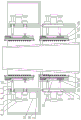
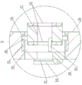
FIG. 1 is a schematic structural view of the present invention; FIG. 2 is a zoom view of the top view of FIG. 1; FIG. 3 is an enlarged view of section I of FIG. 1; fig. 4 is a partial enlarged view of ii of fig. 3.
Detailed Description
In order to make the objects, technical solutions and advantages of the embodiments of the present invention clearer, the technical solutions in the embodiments of the present invention will be clearly and completely described below with reference to the drawings in the embodiments of the present invention, and it is obvious that the described embodiments are some, but not all, embodiments of the present invention. All other embodiments, which can be derived by a person skilled in the art from the embodiments given herein without making any creative effort, shall fall within the protection scope of the present invention.
A lifting platform supporting structure in a wind generating set comprises two drums which are distributed up and down, wherein each drum is composed of four arc-shaped plates 1, the four arc-shaped plates 1 of each drum can be arranged in a straight line shape, adjacent sides of the four arc-shaped plates are hinged through hinged shafts respectively, the adjacent sides of the arc-shaped plates 1 at two ends are connected through bolts, blind holes 2 are formed in two ends of the top side of the arc-shaped plate 1 at the lower side respectively, first electric telescopic rods 3 are fixedly installed in the blind holes 2 respectively, and the upper ends of the first electric telescopic rods 3 are fixedly connected with the bottom sides of the corresponding arc-shaped plates 1 at the upper side respectively; two through holes 4 distributed up and down are respectively arranged in the middle of the upper part of the outer side of the arc-shaped plate 1, an inner threaded pipe 5 is respectively arranged in the through holes 4 in a bearing mode, the outer end of the inner threaded pipe 5 is respectively and fixedly connected with an output shaft of an electromagnetic clutch 6, the electromagnetic clutches 6 are respectively and fixedly connected with the corresponding arc-shaped plates 1, gears 7 are respectively and fixedly arranged on input shafts of the electromagnetic clutches 6, a motor 8 fixedly connected with the corresponding arc-shaped plates 1 is respectively arranged between the two adjacent electromagnetic clutches 6 up and down, the motor 8 is an alternating current servo motor, driving gears 9 are respectively and fixedly arranged on output shafts of the motor 8, the gears 7 are respectively engaged and matched with the corresponding driving gears 9, lead screws 10 are respectively and threadedly arranged in the inner threaded pipe 5, the inner ends of the two adjacent lead screws 10 up and down are respectively provided with a same clamping plate 11, the upper ends of the outer sides, the first inverted T-shaped sliding grooves 12 are internally and respectively and movably provided with first inverted T-shaped sliding blocks 13, the first inverted T-shaped sliding blocks 13 only can slide up and down along the corresponding first inverted T-shaped sliding grooves 12, the outer sides of the first inverted T-shaped sliding blocks 13 are respectively hinged with the inner ends of the corresponding screw rods 10, the top sides and the bottom sides of the clamping plates 11 are respectively provided with a pressure sensor 14, the contact of the pressure sensor 14 faces the inner side, one side of the barrel on the upper side is fixedly provided with a controller 15, the pressure sensor 14 is electrically connected with the input end of the controller 15, the first electric telescopic rod 3, the motor 8 and the electric telescopic rod 6 are respectively and electrically connected with the output end of the controller 15, one side of the arc-shaped magnetic clutch plate 1 on the upper side is fixedly provided with an objective table 16, and the objective table 16 is fixedly arranged, when two object stages 16 are installed, the object stages 16 are respectively fixedly installed at the outer sides of the two symmetrical arc-shaped plates 1. The lifting platform is simple in structure and ingenious in conception, and can be used for flexibly moving and transferring the lifting platform of the wind generating set, so that the lifting platform is suitable for a plurality of wind generating sets, the mounting quantity of the lifting platforms in the wind generating sets is saved, resources are saved, the lifting platform is arranged on the outer side of the tower frame, and large-size objects are conveniently carried, so that the convenience of replacing large parts of the wind generating set is improved, the actual requirements can be met, and the lifting platform is suitable for popularization. The invention is suitable for a round tube tower, and the periphery of the tower is a frustum-shaped multi-edge tube structure, namely an octagonal pyramid-shaped tube, when the invention is used, firstly, a connecting bolt between arc plates 1 at two ends is detached, a barrel consisting of the arc plates 1 is sleeved on the periphery of the octagonal pyramid-shaped tube tower, then the arc plates 1 at two ends are fixedly connected through the bolt, then the angle is adjusted, the inner side of a clamping plate 11 can be just opposite to the side surface of the octagonal pyramid-shaped tube, articles to be carried are placed in an objective table 16, then a controller 15 is electrified, a lifting button of the controller 15 is pressed, the controller 15 controls a motor 8 at the periphery of a lower barrel to rotate, a rotating shaft of the motor 8 drives a gear 7 to rotate through a driving gear 9, the gear 7 drives an input shaft of a corresponding electromagnetic clutch 6 to rotate, at the moment, the controller 15 controls the electromagnetic clutch 6 at the outer side of the lower barrel to be electrified, and the input, The internal thread pipe 5 rotates, the screw rod 10 in the internal thread pipe 5 moves inwards, the screw rod 10 drives the clamping plate 11 to move inwards, the pressure sensor 14 on the lower side is in contact fit with the side wall of the tower frame, the pressure detected by the pressure sensor 14 on the lower side reaches a set value, the correction of the barrel is completed, the center line of the barrel and the tower frame of the octagonal pyramid pipe is collinear at the moment, then the controller 15 controls the electromagnetic clutch 6 on the lower side to be powered off, the upper portion of the clamping plate 11 continues to be close to the side wall of the octagonal pyramid pipe until the pressure monitored by the pressure sensor 14 on the upper side reaches the set value, the inner side of the clamping plate 11 on the lower side is parallel to and in contact fit with the side wall of the octagonal pyramid pipe, the angle of the lower clamping plate 11 is adjusted, and the angle of the clamping plate 11 on the upper; when the objective table 16 starts to ascend, the controller 15 controls all the electromagnetic clutches 6 to be electrified, then controls the motor 8 on the upper side to reversely rotate, the clamping plate 11 on the upper side moves outwards to be opened, the controller 15 controls the upper end of the first electric telescopic rod 3 to drive the barrel on the upper side to upwards move, so that the objective table 16 ascends, the controller 15 controls the motor 8 on the upper side to be electrified to normally rotate, the inner side of the clamping plate 11 is contacted and matched with the side wall of the tower again, until the pressure detected by the corresponding pressure sensor 14 reaches a set value, the motor 8 on the upper side stops rotating, the controller 15 controls the motor 8 on the lower side to be electrified to reversely rotate, so that the clamping plate 11 on the lower side moves outwards to be opened, then the controller 15 controls the first electric telescopic rod 3 to shorten, the motor 8 on the lower side is lifted, the controller 15 controls the motor 8 on the lower side to normally rotate, so that the, when the pressure sensor 14 on the periphery of the lower drum reaches a set value, completing one-time lifting, and continuously repeating the process, so that the object stage 16 can continuously climb upwards along the periphery of the tower; when the stop button of the controller 15 is pressed, the stage 16 can be stopped at a certain height, and when the lowering button of the controller 15 is pressed, the stage 16 is raised in reverse order, and the stage 16 is lowered along the tower.
Specifically, as shown in the figures, the clamping plate 11 according to the embodiment is an inverted T-shaped sliding plate, the inner sides of the inverted T-shaped sliding plate are respectively provided with a vertical plate 17, the outer sides of the vertical plates 17 are respectively provided with a second inverted T-shaped sliding groove 18, the inverted T-shaped sliding plate is respectively located in the second inverted T-shaped sliding groove 18 and can slide up and down, the inner side of the vertical plate 17 is fixedly connected to the outer side of a strip-shaped box 19, the inner side of the strip-shaped box 19 is uniformly provided with a plurality of suction holes 20, the top of the second inverted T-shaped sliding groove 18 is respectively and fixedly provided with a vertical tube 21, the lower end of the vertical tube 21 is open and the upper end is closed, a piston 22 is respectively and movably installed in the vertical tube 21, the outer periphery of the piston 22 is respectively and slidably matched with the inner periphery of the corresponding vertical tube 21, the bottom side of the piston 22 is respectively and fixedly connected to the upper end of a piston rod 23, the lower end, one side of the upper end of the vertical pipe 21 is provided with a through groove 25 communicated with the inside of the corresponding strip-shaped box 19, and the pressure sensors 14 are respectively and fixedly arranged on the top side or the bottom side of the corresponding strip-shaped box 19. After the inner side of the strip-shaped box 19 is attached to the side wall of the tower, under the action of gravity, the lead screw 10 drives the inverted-T-shaped sliding plate to slide downwards along the corresponding second inverted-T-shaped sliding groove 18 respectively, the inverted-T-shaped sliding plate pulls the corresponding piston 22 to move downwards along the vertical pipe 21 through the piston rod 23, negative pressure is formed in the vertical pipe 21 above the piston 22, so that the negative pressure is formed in the strip-shaped box 19 through the through groove 25, finally, suction force is generated on the side wall of the tower through the suction hole 20, the suction force between the clamping plate 11 and the side wall of the tower is increased, the stability and the firmness of the clamping plate 11 are increased, and the clamping plate 11 can be more; when the inner side of the bar box 19 is separated from the side wall of the tower, the piston 22 is moved upwards along the vertical tube 21 by the tension spring 24 to be reset, and the above process is performed in reverse order.
Specifically, as shown in the figures, the outer ends of the suction holes 20 in this embodiment are respectively fixedly mounted with a retaining ring 26, the inner sides of the retaining rings 26 are respectively provided with a moving ring 27, two sides of the moving ring 27 are respectively provided with a rubber pad 28, the inner walls of the suction holes 20 are respectively provided with a bar-shaped sliding chute 29, a sliding block 30 is respectively movably mounted in the bar-shaped sliding chute 29, the outer side of the sliding block 30 is respectively fixedly connected with the outer side of the corresponding bar-shaped sliding chute 29 through a spring 31, and the sliding block 30 is respectively fixedly connected with the corresponding moving ring 27. When the inner side of the strip-shaped box 19 is in contact fit with the corresponding tower side wall, the sliding block 30 moves outwards along the corresponding strip-shaped sliding groove 29, the spring 31 is compressed, the inner side of the rubber pad 28 on the inner side is in close contact fit with the tower side wall, and the outer side of the rubber pad 28 on the outer side is in contact fit with the inner side of the baffle ring 26, so that the suction hole 20 can be in close contact fit with the tower side wall, and the sealing performance between the suction hole 20 and the tower side wall is ensured.
Further, as shown in the drawings, the outer sides of the baffle rings 26 in this embodiment are respectively hinged to the baffles 32 through torsion springs, the baffles 32 close the inner holes of the baffle rings 26, the inner walls of the moving rings 27 are respectively fixedly connected to the inner ends of the push rods 33, and the outer ends of the push rods 33 can respectively contact and cooperate with the inner sides of the corresponding baffles 32. When the outer rubber pad 28 is in contact fit with the inner side of the baffle ring 26, the outer end of the push rod 33 is in contact fit with the inner side of the corresponding baffle plate 32, the outer end of the push rod 33 pushes the baffle plate 32 to rotate along the hinge shaft along with the extrusion of the outer rubber pad 28, so that the inner hole of the baffle ring 26 is opened, and when the push rod 33 is separated from the baffle plate 32, the baffle plate 32 rotates along the hinge shaft under the action of the torsion spring, the inner hole of the baffle ring 26 is closed; when the inner side of the rubber pad 28 on the inner side is not in contact fit with the tower side wall or the rubber pad 28 on the outer side is not pressed, the outer end of the push rod 33 does not push the baffle 32 to open the inner hole of the baffle ring 26, so that the suction hole 20 on the part where the inner side of the strip box 19 is not in contact fit with the tower side wall is in a closed state.
Further, as shown in the drawings, the inner sides of the baffles 32 are respectively fixedly provided with a sealing gasket 34, and the inner sides of the sealing gaskets 34 are respectively in close contact fit with the outer sides of the corresponding baffle rings 26. Under the action of the torsion spring, the inner side of the sealing gasket 34 is in close contact fit with the outer side of the corresponding baffle ring 26, so that the sealing performance of the baffle 32 on the inner hole of the baffle ring 26 is improved.
Furthermore, as shown in the figure, two ends of the top side of the arc plate 1 on the upper side of the embodiment are respectively and fixedly connected with one side of the periphery of the nut 35, the center lines of the adjacent nuts 35 are collinear, and the same bolt 36 is installed in the internal thread. When the arc-shaped plates 1 form a barrel, the bolts 36 can be screwed into the adjacent nuts 25 respectively, so that the stability of the structure of the barrel 1 formed by the arc-shaped plates 1 is further improved.
Finally, it should be noted that: the above examples are only intended to illustrate the technical solution of the present invention, but not to limit it; although the present invention has been described in detail with reference to the foregoing embodiments, it will be understood by those of ordinary skill in the art that: the technical solutions described in the foregoing embodiments may still be modified, or some technical features may be equivalently replaced; and such modifications or substitutions do not depart from the spirit and scope of the corresponding technical solutions of the embodiments of the present invention.
Claims (6)
1. The utility model provides a lift platform bearing structure in wind generating set which characterized in that: the drum comprises two drums which are distributed up and down, wherein each drum is respectively composed of four arc plates (1), the four arc plates (1) of each drum can be arranged in a straight line shape, adjacent sides are respectively hinged and connected through a hinged shaft, the adjacent sides of the arc plates (1) at two ends are connected through bolts, blind holes (2) are respectively formed in two ends of the top side of the arc plate (1) at the lower side, first electric telescopic rods (3) are respectively and fixedly installed in the blind holes (2), and the upper ends of the first electric telescopic rods (3) are respectively and fixedly connected with the bottom sides of the corresponding arc plates (1) at the upper sides; two through holes (4) distributed up and down are respectively formed in the middle of the upper part of the outer side of the arc-shaped plate (1), an inner threaded pipe (5) is respectively installed in each through hole (4) through a bearing, the outer end of each inner threaded pipe (5) is respectively and fixedly connected with the output shaft of an electromagnetic clutch (6), the electromagnetic clutches (6) are respectively and fixedly connected with the corresponding arc-shaped plates (1), gears (7) are respectively and fixedly installed on the input shafts of the electromagnetic clutches (6), a motor (8) fixedly connected with the corresponding arc-shaped plates (1) is respectively arranged between the two adjacent electromagnetic clutches (6) up and down, driving gears (9) are respectively and fixedly installed on the output shafts of the motors (8), the gears (7) are respectively engaged with the corresponding driving gears (9), lead screws (10) are respectively installed in the inner threaded pipes (5), the inner ends of the two lead screws (, the upper end of the outer side of the clamping plate (11) is respectively hinged with the inner end of the corresponding screw rod (10), the lower part of the outer side of the clamping plate (11) is respectively provided with a first inverted T-shaped sliding groove (12), a first inverted T-shaped sliding block (13) is movably arranged in the first inverted T-shaped sliding groove (12), the first inverted T-shaped sliding block (13) can only slide up and down along the corresponding first inverted T-shaped sliding groove (12), the outer side of the first inverted T-shaped sliding block (13) is respectively hinged with the inner end of the corresponding screw rod (10), the top side and the bottom side of the clamping plate (11) are respectively provided with a pressure sensor (14), the contact of the pressure sensor (14) faces the inner side, one side of the barrel at the upper side is fixedly provided with a controller (15), the pressure sensor (14) is electrically connected with the input end of the controller (15), the first electric telescopic rod (3), the motor (8) and the electromagnetic clutch (6) are respectively electrically connected with, an object stage (16) is fixedly arranged on one side of the arc-shaped plate (1) on the upper side.
2. The lifting platform support structure in a wind turbine generator system according to claim 1, wherein: the clamp plate (11) is an inverted T-shaped slide plate, the inner sides of the inverted T-shaped slide plates are respectively provided with a vertical plate (17), the outer sides of the vertical plates (17) are respectively provided with a second inverted T-shaped sliding groove (18), the inverted T-shaped slide plates are respectively positioned in the second inverted T-shaped sliding grooves (18) and can slide up and down along the second inverted T-shaped sliding grooves, the inner sides of the vertical plates (17) are fixedly connected with the outer sides of strip boxes (19), the inner sides of the strip boxes (19) are uniformly provided with a plurality of suction holes (20), the tops of the second inverted T-shaped sliding grooves (18) are respectively and fixedly provided with vertical pipes (21), the lower ends of the vertical pipes (21) are opened and closed, the vertical pipes (21) are respectively and movably provided with pistons (22), the peripheries of the pistons (22) are respectively in sliding contact fit with the inner peripheries of the corresponding vertical pipes (21), the bottom sides of the pistons (22) are respectively and fixedly connected with the upper ends of, the top side of the inverted T-shaped sliding plate is fixedly connected with the bottom side of the vertical pipe (21) through a tension spring (24) sleeved on the periphery of the piston rod (23), a through groove (25) communicated with the interior of the corresponding strip-shaped box (19) is formed in one side of the upper end of the vertical pipe (21), and the pressure sensor (14) is fixedly installed on the top side or the bottom side of the corresponding strip-shaped box (19) respectively.
3. The lifting platform support structure in a wind turbine generator system according to claim 2, wherein: inhale the outer end of hole (20) fixed mounting respectively and keep off ring (26), keep off the inboard of ring (26) and be equipped with shift ring (27) respectively, the both sides of shift ring (27) are equipped with rubber pad (28) respectively, the inner wall of inhaling hole (20) is seted up bar spout (29) respectively, movable mounting slider (30) respectively in bar spout (29), the outside of slider (30) and the outside of the bar spout (29) that correspond are respectively through spring (31) fixed connection, slider (30) respectively with the shift ring (27) fixed connection that corresponds.
4. A lifting platform support structure in a wind turbine generator system according to claim 3, wherein: the outer side of the baffle ring (26) is hinged with the baffle plates (32) through torsion springs respectively, the inner holes of the baffle plates (26) are sealed by the baffle plates (32), the inner wall of the moving ring (27) is fixedly connected with the inner ends of the push rods (33) respectively, and the outer ends of the push rods (33) can be in contact fit with the inner sides of the corresponding baffle plates (32) respectively.
5. The lifting platform support structure in a wind turbine generator system according to claim 4, wherein: the inner sides of the baffles (32) are respectively fixedly provided with a sealing gasket (34), and the inner sides of the sealing gaskets (34) are respectively in close contact fit with the outer sides of the corresponding baffle rings (26).
6. The lifting platform support structure in a wind turbine generator system according to claim 1, wherein: both ends of the top side of the arc-shaped plate (1) on the upper side are fixedly connected with one side of the periphery of the nut (35) respectively, and the center lines of the adjacent nuts (35) are collinear and the same bolt (36) is installed in the internal thread.
Priority Applications (1)
| Application Number | Priority Date | Filing Date | Title |
|---|---|---|---|
| CN201911148875.5A CN110921594B (en) | 2019-11-21 | 2019-11-21 | Lifting platform supporting structure in wind generating set |
Applications Claiming Priority (1)
| Application Number | Priority Date | Filing Date | Title |
|---|---|---|---|
| CN201911148875.5A CN110921594B (en) | 2019-11-21 | 2019-11-21 | Lifting platform supporting structure in wind generating set |
Publications (2)
| Publication Number | Publication Date |
|---|---|
| CN110921594A true CN110921594A (en) | 2020-03-27 |
| CN110921594B CN110921594B (en) | 2020-06-26 |
Family
ID=69850565
Family Applications (1)
| Application Number | Title | Priority Date | Filing Date |
|---|---|---|---|
| CN201911148875.5A Active CN110921594B (en) | 2019-11-21 | 2019-11-21 | Lifting platform supporting structure in wind generating set |
Country Status (1)
| Country | Link |
|---|---|
| CN (1) | CN110921594B (en) |
Cited By (1)
| Publication number | Priority date | Publication date | Assignee | Title |
|---|---|---|---|---|
| CN113053652A (en) * | 2021-03-30 | 2021-06-29 | 铜陵日科电子有限责任公司 | Transformer processing fixing device |
Citations (8)
| Publication number | Priority date | Publication date | Assignee | Title |
|---|---|---|---|---|
| CN101297114A (en) * | 2005-10-27 | 2008-10-29 | 歌美飒创新技术公司 | Nacelle lifting tool and method |
| CN101786586A (en) * | 2010-04-09 | 2010-07-28 | 太原重工股份有限公司 | Large-diameter cylinder body outer wall climbing device |
| EP2368834A1 (en) * | 2010-03-22 | 2011-09-28 | FCC Construccion, S.A | Equipment for raising/lowering of wind generator turbines |
| CN202032175U (en) * | 2011-03-30 | 2011-11-09 | 上海锅炉厂有限公司 | Pipeline guiding device |
| CN202297047U (en) * | 2011-09-29 | 2012-07-04 | 张德利 | Hanging basket for blade of wind driven generator |
| CN202440279U (en) * | 2012-02-08 | 2012-09-19 | 赵传明 | Tower drum climbing machine |
| CN103009030A (en) * | 2011-09-20 | 2013-04-03 | 通用电气公司 | Component handling system for use in wind turbines |
| CN106495054A (en) * | 2015-09-07 | 2017-03-15 | 孙燕平 | Single track tooth bar electric lift |
-
2019
- 2019-11-21 CN CN201911148875.5A patent/CN110921594B/en active Active
Patent Citations (8)
| Publication number | Priority date | Publication date | Assignee | Title |
|---|---|---|---|---|
| CN101297114A (en) * | 2005-10-27 | 2008-10-29 | 歌美飒创新技术公司 | Nacelle lifting tool and method |
| EP2368834A1 (en) * | 2010-03-22 | 2011-09-28 | FCC Construccion, S.A | Equipment for raising/lowering of wind generator turbines |
| CN101786586A (en) * | 2010-04-09 | 2010-07-28 | 太原重工股份有限公司 | Large-diameter cylinder body outer wall climbing device |
| CN202032175U (en) * | 2011-03-30 | 2011-11-09 | 上海锅炉厂有限公司 | Pipeline guiding device |
| CN103009030A (en) * | 2011-09-20 | 2013-04-03 | 通用电气公司 | Component handling system for use in wind turbines |
| CN202297047U (en) * | 2011-09-29 | 2012-07-04 | 张德利 | Hanging basket for blade of wind driven generator |
| CN202440279U (en) * | 2012-02-08 | 2012-09-19 | 赵传明 | Tower drum climbing machine |
| CN106495054A (en) * | 2015-09-07 | 2017-03-15 | 孙燕平 | Single track tooth bar electric lift |
Cited By (1)
| Publication number | Priority date | Publication date | Assignee | Title |
|---|---|---|---|---|
| CN113053652A (en) * | 2021-03-30 | 2021-06-29 | 铜陵日科电子有限责任公司 | Transformer processing fixing device |
Also Published As
| Publication number | Publication date |
|---|---|
| CN110921594B (en) | 2020-06-26 |
Similar Documents
| Publication | Publication Date | Title |
|---|---|---|
| CN103256817B (en) | Feeding device for aluminum bar heating furnace | |
| CN108996426B (en) | Storage battery maintenance and inspection device based on automobile | |
| CN204716124U (en) | Portable removable level-sensing device inspection platform | |
| CN110921594B (en) | Lifting platform supporting structure in wind generating set | |
| CN205257788U (en) | Full -automatic intelligent grabbing device | |
| CN206278864U (en) | A kind of simple machine hoisting device safeguarded for power equipment | |
| CN108838954A (en) | A kind of novel and multifunctional mechanical equipment inspection rack device and its repair method | |
| CN206800973U (en) | A kind of packaged type building hanging basket | |
| CN111099345A (en) | Conveying device for communication equipment production | |
| CN207027479U (en) | A kind of numerically controlled lathe repairs climbing frame | |
| CN213414525U (en) | Punching die placing frame | |
| CN213141282U (en) | Lifting device for auto repair | |
| CN213231280U (en) | Lifting device with protection effect for decoration construction | |
| CN212687411U (en) | Crane for dismounting wind driven generator | |
| CN210340203U (en) | New forms of energy group battery lifting devices | |
| CN210885009U (en) | Equipment hoisting alignment device for wind power generation | |
| CN2433649Y (en) | Automatic PS plate drying machine | |
| CN217021591U (en) | White spirit packing carton front cover pasting mould | |
| CN216721257U (en) | Photovoltaic solar panel angle bead installation device | |
| CN214243712U (en) | Dedicated jacking equipment of electromechanical installation | |
| CN211377354U (en) | Substation equipment overhauls frame | |
| CN109516193A (en) | Paper support grasping mechanism | |
| CN217650788U (en) | Automatic elevator for distribution live working | |
| CN113824042B (en) | Movable cable accessory installation box | |
| CN219321932U (en) | Box-type substation with stable hoisting |
Legal Events
| Date | Code | Title | Description |
|---|---|---|---|
| PB01 | Publication | ||
| PB01 | Publication | ||
| SE01 | Entry into force of request for substantive examination | ||
| SE01 | Entry into force of request for substantive examination | ||
| GR01 | Patent grant | ||
| GR01 | Patent grant | ||
| PE01 | Entry into force of the registration of the contract for pledge of patent right |
Denomination of invention: A lifting platform support structure inside wind turbines Effective date of registration: 20230605 Granted publication date: 20200626 Pledgee: Qilu bank Limited by Share Ltd. Ji'nan Jiyang branch Pledgor: SHANDONG KINGLIFT GROUP Co.,Ltd. Registration number: Y2023980042858 |
|
| PE01 | Entry into force of the registration of the contract for pledge of patent right |