CN110892198A - Cooking appliance with a retractable door with a special retaining spring for the bearing bush - Google Patents
Cooking appliance with a retractable door with a special retaining spring for the bearing bush Download PDFInfo
- Publication number
- CN110892198A CN110892198A CN201880049736.4A CN201880049736A CN110892198A CN 110892198 A CN110892198 A CN 110892198A CN 201880049736 A CN201880049736 A CN 201880049736A CN 110892198 A CN110892198 A CN 110892198A
- Authority
- CN
- China
- Prior art keywords
- door
- cooking appliance
- cooking
- housing
- guide element
- Prior art date
- Legal status (The legal status is an assumption and is not a legal conclusion. Google has not performed a legal analysis and makes no representation as to the accuracy of the status listed.)
- Pending
Links
Images


Classifications
-
- F—MECHANICAL ENGINEERING; LIGHTING; HEATING; WEAPONS; BLASTING
- F24—HEATING; RANGES; VENTILATING
- F24C—DOMESTIC STOVES OR RANGES ; DETAILS OF DOMESTIC STOVES OR RANGES, OF GENERAL APPLICATION
- F24C15/00—Details
- F24C15/02—Doors specially adapted for stoves or ranges
- F24C15/026—Doors specially adapted for stoves or ranges stowing of door in open position
-
- F—MECHANICAL ENGINEERING; LIGHTING; HEATING; WEAPONS; BLASTING
- F24—HEATING; RANGES; VENTILATING
- F24C—DOMESTIC STOVES OR RANGES ; DETAILS OF DOMESTIC STOVES OR RANGES, OF GENERAL APPLICATION
- F24C15/00—Details
- F24C15/02—Doors specially adapted for stoves or ranges
- F24C15/04—Doors specially adapted for stoves or ranges with transparent panels
- F24C15/045—Doors specially adapted for stoves or ranges with transparent panels being dismountable, e.g. giving access for cleaning
-
- F—MECHANICAL ENGINEERING; LIGHTING; HEATING; WEAPONS; BLASTING
- F24—HEATING; RANGES; VENTILATING
- F24C—DOMESTIC STOVES OR RANGES ; DETAILS OF DOMESTIC STOVES OR RANGES, OF GENERAL APPLICATION
- F24C15/00—Details
- F24C15/02—Doors specially adapted for stoves or ranges
- F24C15/023—Mounting of doors, e.g. hinges, counterbalancing
Abstract
The invention relates to a cooking appliance (1) having a housing (2) in which a cooking chamber (3) is formed and having a door (4) for closing the cooking chamber (3) which is arranged on the housing (2) in a movable manner, wherein a handle (6) is arranged in a stationary manner on the door (4) and the cooking appliance has a storage chamber (7) which is separate from the cooking chamber (3) and which is formed in the housing (3) and into which the door (4) can be lowered in the open state, wherein the storage chamber (7) has at least one guide rail (10, 11) in which a guide element (18, 19) of the door (4) is guided, wherein the guide element (18, 19) is mounted on the door (4) in a movable manner and is held directly with the door (4) The first end (29 a) of the spring (29) is connected, and at least one coupling point of the guide element (18, 19) is held on the door (4) by means of the holding spring.
Description
Technical Field
The invention relates to a cooking appliance having a housing in which a cooking chamber is formed. The cooking appliance has a door for closing the cooking chamber. The door is movably disposed on the housing. A handle is arranged on the door in a stationary and thus immovable manner. The cooking appliance has a storage chamber, which is separate from the cooking chamber and is formed in the housing, in which storage chamber the door can be lowered in its open state. The storage compartment has at least one guide rail in which a guide element of the door is guided.
Background
It is known for cooking appliances that a door for closing the cooking chamber in the open state is arranged in a sunken manner in such a storage chamber. This makes it possible to achieve a space-saving solution which makes it possible to access the cooking chamber without restrictions and in a close manner on the front side. In contrast to a hinged door, which is arranged only pivotably on the housing, the use of such a retractable door offers the possibility of being very close to the cooking chamber in the open state. This simplifies the handling for equipping the cooking chamber or for removing objects from the cooking chamber. The impact of the impact on the open door is thereby also minimized, so that undesired thermal effects on the user are also avoided.
Such a retractable door in a cooking appliance is known from the prior art. In this connection, it is also known that such doors also have a handle which is arranged in a movable manner on the door itself. This is achieved in that, when the door is pivoted and lowered into the storage space, the handle is likewise pivoted relative to the door leaf on which the handle is arranged. In the fully open state, in which the door leaf is oriented substantially in a horizontal plane, the door handle is thereby pivoted such that it can be grasped at the front. In order to be able to achieve this additional pivotability of the handle, relatively complicated mechanical devices are constructed. This requires additional installation space and increases the weight of the door.
In order to overcome this, in an alternative embodiment it can be provided that the handle is arranged on the door leaf in a positionally fixed and thus immovable manner. This means that the handle itself does not pivot when the door and thus also when the door leaf pivots. Such a design is known, for example, from DE 1274306. A disadvantage of this design is that the door is fixedly mounted and cannot be removed to some extent. Thereby making maintenance work and cleaning difficult.
Disclosure of Invention
The object of the present invention is to provide a cooking appliance having a door which can be lowered into a storage space and which has a handle arranged in a stationary manner on a door leaf, wherein the operability of the door is simplified as a separate component.
This object is achieved by a cooking appliance having the features of claim 1.
According to one aspect of the present invention, a cooking appliance is provided having a housing in which a cooking chamber is configured. The cooking appliance has a door for closing the cooking chamber. The door is movably disposed on the housing. A handle is arranged on the door in a stationary and thus immovable manner. This means in particular that the handle does not move relative to the door leaf on which it is arranged when the door is moved. Furthermore, the cooking appliance has a storage chamber which is separate from the cooking chamber and is formed in the housing, into which the door can be lowered in the open state. The storage compartment has at least one guide rail in which a guide element of the door is guided. The movement of the door into and out of the storage chamber is thereby specified in a very defined manner, so that this can be carried out without pinching (klemmfrei) and smoothly (ruckfrei) and very simply.
The guide element is movably mounted on the door and is directly connected to a first end of a retaining spring of the door. By means of the retaining spring, the coupling position of the guide element is retained on the door. This embodiment makes it possible to easily and reversibly detach and reassemble the door from the housing without damage, simply and quickly. In order to be able to achieve this simply and reliably as well, defined coupling positions of the guide elements are required. However, since the guide element is also to be mounted in a movable manner, this defined coupling position is required for mounting the door on the housing. In order not to undesirably adjust the coupling position or in principle not even to occur (vorfinden) due to the movable mounting, the coupling position is held by means of a special holding element, i.e. in particular a holding spring. The retaining spring is a particularly advantageous component for this purpose, since on the one hand the coupling position is reliably retained and on the other hand a very continuous movement possibility of the guide element is provided, which is then also predetermined by the spring. On the other hand, when the coupling position is released after assembly, it is also possible to achieve this automatically again by the retaining spring, since the retaining spring automatically forms the (einstellen) coupling position again upon removal by its subsequent pretensioning. A mechanically stable and component-minimized coupling mechanism is also provided by the specific connection of the retaining springs.
Provision is preferably made for the door to have a holding angle (halfwinkel) for holding a door glass of the door. The second end of the holding spring is directly connected to the holding bracket. This is also a mechanically stable, component-reducing design. In addition, such a holding bracket, which is then present anyway, is a multifunctional component which is designed on the one hand for holding the door glass and on the other hand for holding the second end of the spring.
Preferably, the first end of the retaining spring is configured as a hook and is arranged in such a way that it engages into a lead-through in the radial tab of the guide element. A particularly reliable and simple mechanical coupling of the retaining spring directly to the guide element is thereby achieved.
In particular, the retaining spring is a helical spring.
In an advantageous embodiment, the lead-through is configured as a keyhole-shaped geometry. On the one hand, this enables the first end of the retaining spring to be inserted into the insertion section very easily and reliably. On the other hand, it is also achieved that in the end position, in which the first end then engages in the tapered section of the keyhole geometry, as little play as possible and therefore a movement tolerance is provided for the first end. Undesired slipping of the spring and undesired noise development during the movement of the door are thereby avoided. In particular, undesired jumping of the retaining spring (Verspringen) in the event of such a movement is thereby avoided.
Preferably, a damping element for damping frictional noise between the retaining spring and the lead-through is arranged on a limiting wall of the lead-through. On the one hand, smooth movement is also possible as a result, and in particular a particularly noise-reducing bearing of the retaining spring is achieved in a particularly advantageous manner.
In a further advantageous embodiment, it is provided that the retaining spring is surrounded by a tubular housing. The housing is in particular a noise reduction element. The noise occurring during the tensioning and relaxing of the retaining spring is at least strongly damped by the sheathing, so that no undesired outward noise or an undesired strong perception of noise occurs here either. Such a hose-like housing is preferably of elastically deformable design and may be, for example, a hose made of an elastomer.
It can be provided that the length of the housing, measured in the direction of its longitudinal axis, corresponds to the length corresponding to the inlet area or axial extension of the spiral coil (spiralwind) of the retaining spring when the retaining spring is in the untensioned state. This means that if the spring is tensioned and thus pulled apart, this area with the spiral wrap will become longer than the length of the casing. On the one hand, the possibility of movement of the retaining spring is thus not limited, and on the other hand, the length of the housing is sufficient to sufficiently reduce noise.
In another embodiment, however, it can also be provided that the length of the housing is greater. This can be advantageous in particular if the housing is not fixed in length but is constructed variable in length. For example, in such an embodiment, the housing may be configured as a bellows. With this embodiment, the length of the helical spring region holding the spring can also be varied together by the housing.
In an advantageous embodiment, the guide element is designed as a bearing bush (Lagerbuchse). In the embodiment as a bearing bush, the bearing bush is then coupled in particular directly to the limiting element of the guide rail. Provision can therefore be made for the bearing bush to have a guide groove into which the guide wall of the guide rail or the guide runner engages. The design as a bushing is furthermore designed in particular in such a way that a hollow region is formed, with which the bearing sleeves can then be inserted, for example, onto a coupling element, such as a coupling rod. In particular, the receptacle is configured as a blind hole. The bearing sleeve is therefore not a tubular component in particular, but is closed on one end side.
In an advantageous embodiment, it is provided that the guide element has an integrated adjusting pin, by means of which the assembled state of the door can be released from the receptacle arranged on the guide rail. The adjusting pin must be held in the assembly position, in particular by a retaining spring, in order to be able to mount the door on the housing. After assembly, the adjusting pin is then in a retaining position which is different from its assembly position, so that an undesired loosening or automatic falling of the door from the housing is avoided. The adjusting pin is arranged at the end on the guide element and is oriented in a freely protruding manner (kragent).
Preferably, it is provided that the adjusting pin is beam-shaped and is arranged with its longitudinal axis in the coupling or assembly position at an angle of between 20 ° and 60 ° relative to the vertical axis of the door. By means of this particular coupling or assembly position, a simple, quick and reliable mounting of the door on the housing can be achieved, and the assembly process or assembly movement can be carried out simply and intuitively. Thereby, the assembly process of the door on the housing can be performed simply, quickly and reliably.
Provision is preferably made for the door to have an upper, hood-shaped covering strip. The cover strip is a separate component and may also be referred to as a top panel (toppanede). The covering strip is in particular of one-piece construction, in particular of plastic.
In a further advantageous embodiment, the door has a glass pane stack (scheibenpaker) with at least one front glass and an inner glass. The front glass is the outermost glass of this glass plate group facing away from the cooking chamber. The front glass is designed in particular such that it covers the above-mentioned covering strip on the front side in the assembled state. The surface size and the positioning of the front glass are therefore selected such that the covering strip located behind it, viewed in the depth direction of the cooking appliance, is covered on the front. This also protects the covering strip and creates a quiet appearance of the door on the front.
An embodiment can also be provided in which the cover strip is not covered on the front side by the front glass.
In a further advantageous embodiment, it is provided that the covering strip has a separate reinforcement for reinforcing the covering strip. This is advantageous because, for cooking appliances having a pyrolysis operation, undesirable deformation of the covering element, in particular of plastic, or of the covering strip, is avoided in the pyrolysis operation. It is precisely when the user pulls on the door with a relatively high force during such a pyrolysis operation that this may lead to an undesired deformation of the covering strip, which is then avoided by the at least one additional reinforcement. The reinforcement can be arranged on the front glass and then the cover strip is pushed or inserted onto the front glass. In particular, a screw connection to the front glass can also be provided here.
In an advantageous embodiment, it is provided that this reinforcement also additionally has the function of a locking element with which the door is locked in its closed position during the pyrolysis operation of the cooking appliance.
Preferably, at least one stop is formed in the storage chamber, which limits the insertion depth of the door into the storage chamber in such a way that the handle is positioned at a distance from the front of the cooking appliance in the maximum pushed-in position of the door. In particular, it is provided that, in the maximum pushed-in position between the front side of the housing and the upper edge of the door, which is not necessarily equal to the upper edge of the handle, the handle can also be arranged in this respect at a distance of between 80mm and 90mm, in particular 85mm, from the upper edge of the door.
In an advantageous embodiment, it is provided that the door is designed such that different front panes of the above-mentioned glass pane package can be fitted. In particular, different colored glasses can be used here, so that different variants can be formed with regard to the optical appearance of the front side. In this way, a uniform visual front appearance can be formed by the optionally additionally present switch or operating panel of the cooking appliance, which is preferably arranged adjacent to the door.
It is also possible to mount a covering strip on the door with at least two different variants. Therefore, a cover strip for a cooking appliance having a pyrolysis operation can be provided. However, it is also possible to provide different cover strips, which are suitable for cooking appliances that do not have a pyrolysis operation. In particular, identical components are provided in this connection, which enable the connection of the cover strip variants.
Preferably, the handle of the door is fixed, in particular screwed, to the front glass. For this purpose, the front glass preferably has two guides or holes through which bolts can be passed. It is preferably provided that a reinforcement which can be arranged on the cover strip and is used to reinforce the cover strip is likewise screwed to the front glass. For this purpose, it can be provided in particular that the threaded connection is made by means of such a threaded hole, to which the handle is also screwed. Thereby, the holding points are locally limited and the number of feedthroughs or bolt holes in the front glass is minimized.
In one embodiment, it can be provided that the guide element is formed in one piece. The guide element can preferably be made of plastic.
The positions and orientations given when the appliance is used and arranged in accordance with regulations are explained by expressions of "above", "below", "front", "rear", "horizontal", "vertical", "depth direction", "width direction", "height direction", and the like.
Further features of the invention emerge from the claims, the figures and the description of the figures. The features and feature combinations mentioned above in the description and the features and feature combinations mentioned below in the description of the figures and/or shown in the figures individually can be used not only in the respectively given combination but also in other combinations without departing from the scope of the invention. Thus, embodiments of the invention that are not explicitly shown and described in the drawings, but which result from and can be produced by individual combinations of features from the described embodiments, are also considered to be included in and disclosed. Thus, embodiments and combinations of features not possessing all the characteristics of the originally filed independent claims should also be considered disclosed. Furthermore, embodiments and combinations of features beyond or deviating from the combinations of features recited in the cited claims shall be regarded as being disclosed, in particular by the embodiments recited above.
Drawings
Embodiments of the invention are explained in detail below with the aid of schematic drawings. In which is shown:
fig. 1 shows a perspective view of an embodiment of a cooking appliance according to the invention;
FIG. 2 illustrates an exploded view of one embodiment of a door;
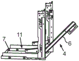
fig. 3 shows a schematic representation of a sub-assembly of the cooking appliance according to fig. 1 with the door partially open;
fig. 4 shows a diagrammatic view of the assembly according to fig. 3, with the door fully open and pushed into the storage compartment;
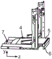
fig. 5 shows a side view of the illustration according to fig. 4;
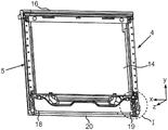
fig. 6 shows a perspective view of the door according to fig. 2 in an assembled state;
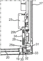
figure 7 shows an enlarged view of a part of the door according to figure 6;
figure 8 shows a partial illustration of one side region of the door according to figures 6 and 7;
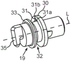
FIG. 9 shows a perspective view of one embodiment of a guide element of the door configured as a bearing sleeve;
FIG. 10 shows a perspective view of a partial region of a door;
fig. 11 shows a side view of the bearing sleeve according to fig. 9, and
fig. 12 shows a perspective view with a bearing sleeve and other components.
In the figures, identical or functionally identical elements are provided with the same reference signs.
Detailed Description
Fig. 1 shows a cooking appliance 1, which may be, for example, an oven, a microwave cooking appliance, a steam cooking appliance or a combination of the above. The cooking appliance 1 has a housing 2, in which housing 2 a cooking chamber 3 for cooking food is formed. Furthermore, the cooking appliance 1 has a door 4, which is designed to close the cooking chamber 3 on the front side. The door 4 has a door leaf 5, which is designed as a plate-like part. On the door leaf 5, a handle 6 is arranged on the front side and thus faces away from the cooking chamber 3. The handle 6 is arranged in a stationary manner and is therefore immovably attached, in particular screwed, to the door leaf 5. The door 4 is shown in a closed state in fig. 1. The door leaf 5 is then oriented in a vertical plane, i.e. in the x-y plane, in this embodiment.
Furthermore, the cooking appliance 1 has a storage chamber 7 which is formed separately from the cooking chamber 3 and is formed below the cooking chamber 3 in the housing 2 in the height direction (y direction). The door 4 can be pushed or sunk into said storage chamber 7 in the open state. The position of the handle 6 on the door leaf 5 relative to the door leaf 5 does not change even when the door 4 is moved.
In this exemplary embodiment, the cooking appliance 1 also has an operating panel 8, on which an operating and/or display device 9 is preferably formed.
The storage chamber 7 is delimited by walls, wherein in particular two opposite side walls have a guide rail 10 and 11, respectively, in which the guide elements of the door 4 are guided.
One embodiment of the door 4 is shown in an exploded view in fig. 2. The plate-shaped door leaf 5 has a glass pane stack 12, wherein the glass pane stack 12 has a front glass 13, an inner glass 14 and here in particular also an intermediate glass 15. The three panes 13 to 15 are arranged in particular parallel to one another and spaced apart from one another. The door 4 furthermore has a covering strip 16, which is designed as a cover or a top panel placed thereon. The covering strip 16 is preferably formed in one piece and in particular from plastic. It covers the door leaf 5 from above.
Furthermore, the door 4 has a frame 17, which is designed in multiple parts and on which the glass panel group 12 is held.
The door 4 furthermore has the already mentioned guide elements, which are designed here as bearing sleeves 18, 19. In this embodiment, two bearing sleeves are positioned at opposite ends in the width direction of the door and are preferably connected by a connecting rod 20. The bearing sleeves 18 and 19 are pushed tightly onto the connecting rod 20. One of the bearing sleeves 18, 19 is then arranged in such a way that it engages into the guide rails 10, 11, so that the lowering movement of the door 4 into the storage chamber 7 or out of the storage chamber 7 takes place and therefore takes place particularly smoothly and without opening (versprezhei).
In addition, the bearing sleeves 18 and 19 are also held by bores 21 and 22, which are formed in the frame part or frame profile of the frame 17.
Furthermore, as can be seen, a plurality of holding angles 23 are arranged on the inner side 13a of the front glass 13, which form bonding angles.
It can also be seen that the two leadthroughs 24 and 25 in the front pane 13 are in the form of bolt holes through which bolts can be passed, in order to be able to fix the handle 6 to the front pane 13 in a stationary manner.
As can be seen in fig. 1 and is shown in fig. 2, the front glass 13 has a height (extension in the y direction) such that the covering strip 16 is covered, in particular completely covered, by the front glass 13 when the door 4 is viewed from the front.
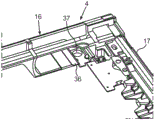
Fig. 3 shows a subassembly of the cooking appliance 1, wherein the door 4 is shown in a partially opened state, but has not yet been moved into the storage space 7.
For this purpose, fig. 4 shows a representation in which the door 4 is completely open and is lowered into the storage space 7.
As can already be seen in fig. 4, the door 4 and in particular the door leaf 5 in this maximum pushed-in position nevertheless project a certain length forward from the storage space 7. The maximum insertion depth of the door 4 and in particular of the door leaf 5 in this end position is such that the distance a between the front face 26 of the housing 2 and the upper edge 27 of the door 4 and in particular of the door leaf 5 lies between 80mm and 90mm, in particular 85 mm. The maximum insertion depth and thus the spacing a are selected such that the handle 6 is positioned in the depth direction to be gripped by hand from the rear at a distance from the front 26, as can be seen in fig. 5. Furthermore, as shown in fig. 5, a stop 28 is arranged in the storage chamber 7, which stop defines the maximum insertion depth of the door 4.
Fig. 6 shows the door 4 in an assembled state. Here, the door 4 is shown in a view towards the inner glass 14.
The bearing bushes 18 and 19 are arranged on the door 4 in a movable manner such that they can be rotated about an axis which is oriented in the width direction (x direction) and is in particular predefined by the connecting rod 20. In this connection, a relative movement relative to the door leaf 5 is thus possible.
If a specific coupling point or coupling point of the bearing sleeves 18 and 19 is formed in this connection, the door 4 can be mounted on the housing 2, which coupling point or coupling point is the mounting point. However, the coupling position of the bearing sleeves 18, 19 is a specific rotational position about the rotational axis, which must first be formed and in connection therewith specifically maintained.
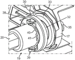
For this purpose, the door 4 has a retaining spring 29, as can be better seen in the enlarged view in fig. 7. The enlarged region I in fig. 6 shown in fig. 7 shows that the retaining spring 29 is directly connected with the bearing sleeve 19 with a first end 29a, which is bent in the shape of a hook.
In the embodiment shown here, the bearing sleeve 19 has a radial web 30 with a lead-through 31 in the form of a bore, through which the first end 29a is guided and suspended. The radial webs 30 also form the boundary of the slots 32. On the other hand, the groove 32 is delimited by a further radial web 33. The groove 32 is used to produce a coupling with a guide runner of the guide rail 11, wherein the guide runner engages into the groove 32.
Furthermore, the holding spring 29, in particular a helical spring, is suspended with a second end 29b opposite the first end 29a directly from a holding bracket 23, which is provided for holding the front glass 13 and is glued to the front glass 13.
Furthermore, the door 4 has a hose-like casing 34 surrounding the retaining spring 29. In the axial direction, the length of this housing 34 corresponds to the area of the spiral winding with the retaining spring 29 when the retaining spring 29 is in the relaxed state. In contrast, fig. 7 shows a tensioned state in which the rolls are pulled apart from one another. Thus, only a partial region of the spiral wraps is surrounded by the hose-like casings 34. The hose-like casing 34 constitutes a noise reducing element. It may be made of an elastic material, for example an elastomer.
The above-mentioned coupling position of the guide element 29 is held in position by a holding spring 29. Furthermore, it is also possible by means of the retaining spring 29 that if the bearing sleeve 19 is pivoted out of the coupling position in the assembled state, the coupling position is automatically formed again when the door 4 is subsequently detached from the housing 2.
In a further embodiment according to fig. 7, it can also be provided that the housing 34 is not length-stable, but rather is of variable length design and can be, for example, a bellows. In this type of embodiment, the housing 34 can be varied as a function of the length of the helical region of the retaining spring 29, so that in the tensioned state of the retaining spring 29 the helical region is in particular completely enclosed by the housing 34.
On the opposite side of the bearing sleeve 18, the door 4 is preferably configured accordingly.
Fig. 8 shows an enlarged view of the door 4, wherein the outer end of the bearing sleeve 19 is seen here, as can be seen, the bearing sleeve 19 has an adjusting pin 35 in one piece, which is of beam-like design and is freely arranged or projects laterally freely, the door leaf 5 has a vertical axis H which is oriented in the height direction in the closed state of the door 4, in contrast to which the beam-like adjusting pin 35 is arranged obliquely to the longitudinal axis K, wherein the angle α can be between 10 ° and 40 °, in particular between 10 ° and 30 °, the above-mentioned coupling position of the bearing sleeve 19 and thus of the adjusting pin 35 is shown in fig. 8 in this connection.
An enlarged view of an embodiment of the bearing sleeve 19 is shown in fig. 9. It can also be seen here that the leadthrough 31 has the shape of a keyhole or the type of keyhole geometry. As can be seen here, a region 31a facing the longitudinal axis L of the bearing sleeve 19 is widened in order to enable simple insertion of the end 29 a. The further region 31b of the lead-through 31, which is radially spaced apart from this and therefore further outside from the longitudinal axis L, tapers opposite thereto. In the final assembled state, the hook-shaped end 29a is supported in this tapered region 31 b. It can be provided that the delimiting walls of the lead-through 31 are covered with a noise-reducing material, for example provided with a sealing element or a corresponding coating. For this purpose, for example, the suspension ear opening can be sheathed with a plastic sleeve or a sealing ring can be arranged on the delimiting wall.
Fig. 10 shows a further detail of the door 4 in a perspective view, wherein here the corner region with the upper part of the cover strip 16 is shown. A reinforcing element 36, which is separate therefrom, can be arranged on the covering strip 16, in particular inserted. The reinforcing member 36 may be made of metal. The reinforcement serves, in particular during the pyrolysis operation of the cooking appliance 1, to reinforce the covering strip 16 made of plastic, so that it is not deformed undesirably, in particular when pulled over it. Preferably, the reinforcement 36 is screwed onto the front glass 13, wherein a lead-through 37 for a screw is provided here. In particular, the lead-through 37 then coincides with the lead-through 25, so that the same screw connection as for the handle 6 is also provided for this reinforcement 36. The reinforcement 36 can additionally also serve as a locking element for locking the door 4 during the pyrolysis operation.
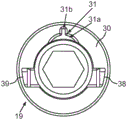
Fig. 11 shows a side view of the bearing sleeve 19. The geometry of the lead-through 31 is shown in more detail here. Furthermore, in this example, wing- like stops 38, 39 are formed, which are oriented in the axial direction and are arranged radially spaced apart from the base tube of the bearing sleeve 19. The stops 38, 39 prevent the spring-out of a stop spring 40, with which the position of the bearing sleeve 19 on the connecting rod 20 is fixed. The retaining spring 40 is shown in a perspective view according to fig. 12. A retaining spring 40, which is designed as a wire spring, engages with an arcuate region into an opening 41 in the base tube of the bearing sleeve 19. The arcuate region engages the wall of the base pipe to mechanically couple to the tie rod 20 and fix its position.
List of reference numerals
1 cooking appliance
2 casing
3 cooking chamber
4 door
5 door leaf
6 handle
7 storage space
8 operating panel
9 operating/display device
10 guide rail
11 guide rail
12 glass plate group
13 front glass
13a inside
14 inner glass
15 intermediate glass
16 cover strip
17 frame
18 guide element
19 guide element
20 connecting rod
21 holes
22 holes
23 holding angle piece
24 threading part
25 threading part
26 front side
27 upper edge
28 stop
29 holding spring
29a first end portion
29b second end
30 radial tab
31 threading part
32 groove
33 radial tab
34 cover
35 adjusting pin
36 stiffener
37 threading part
38 stop
39 stop
40 stop spring
41 opening
I region
a distance between
H vertical axis
Longitudinal axis of K
L longitudinal axis
α angle.
Claims (13)
1. Cooking appliance (1) having a housing (2) in which a cooking chamber (3) is formed and having a door (4) for closing the cooking chamber (3) which is arranged on the housing (2) in a movable manner, wherein a handle (6) is arranged in a stationary manner on the door (4) and the cooking appliance has a storage chamber (7) which is separate from the cooking chamber (3) and which is formed in the housing (3) and into which the door (4) can be lowered in the open state, wherein the storage chamber (7) has at least one guide rail (10, 11) in which a guide element (18, 19) of the door (4) is guided, characterized in that the guide element (18, 19) is mounted on the door (4) in a movable manner and is directly connected to a retaining spring of the door (4) (29) Is connected, at least one coupling position of the guide element (18, 19) being held on the door (4) by means of the holding spring.
2. The cooking appliance (1) according to claim 1, characterised in that the door (4) has a holding angle (23) for the door glass (13, 14, 15) of the door (4) and the second end (29 b) of the holding spring (29) is directly connected to the holding angle (23).
3. The cooking appliance (1) according to claim 1 or 2, characterized in that the first end (29 a) of the retaining spring (29) is configured as a hook and engages into a threading (31) within a radial tab (30) of the guide element (18, 19).
4. Cooking appliance (1) according to claim 3, characterized in that the lead-through (31) has a keyhole geometry.
5. Cooking appliance (1) according to claim 3 or 4, characterized in that a damping element for damping the frictional noise of the holding spring (29) is arranged on a delimiting wall of the lead-through (31).
6. Cooking appliance (1) according to any of the preceding claims, characterized in that the retaining spring (29) is surrounded by a hose-like casing (34).
7. Cooking appliance (1) according to any of the preceding claims, characterized in that the guiding element is a bearing sleeve (18, 19).
8. Cooking appliance (1) according to one of the preceding claims, characterized in that the guide element (18, 19) has an integrated adjustment pin (35) by means of which the release of the assembled state of the door (4) on the guide rail (10, 11) can be performed.
9. The cooking appliance (1) according to claim 8, characterized in that the adjusting pin (35) is configured beam-like and is arranged with its longitudinal axis (L) in the coupled position at an angle of between 10 ° and 40 ° with respect to a vertical axis (H) of the door (4).
10. The cooking appliance (1) according to any one of the preceding claims, wherein the door (4) has an upper covering strip (16).
11. The cooking appliance (1) according to claim 10, characterised in that the door (4) has a front glass (13) as door glass, which is arranged such that it covers the covering strip (16) at the front.
12. The cooking appliance (1) according to claim 10 or 11, characterized in that the door (4) has a reinforcement (36) for reinforcing the covering strip (16), which is arranged on the covering strip (16).
13. Cooking appliance (1) according to one of the preceding claims, characterized in that a stop (28) is configured in the storage chamber (7) which limits the insertion depth of the door (4) in such a way that the handle (6) is positioned spaced apart from a front face (26) of the cooking appliance (1) in the maximum pushed-in position of the door (4), in particular an upper edge (27) of the door (4) is arranged at a distance (a) of between 80mm and 90mm from the front face (26).
Applications Claiming Priority (3)
| Application Number | Priority Date | Filing Date | Title |
|---|---|---|---|
| DE102017213095.4A DE102017213095A1 (en) | 2017-07-28 | 2017-07-28 | Cooking appliance with retractable door, which has a specific retaining spring for a bearing bush |
| DE102017213095.4 | 2017-07-28 | ||
| PCT/EP2018/068534 WO2019020355A1 (en) | 2017-07-28 | 2018-07-09 | Cooking appliance comprising a lowerable door, which has a specific retaining spring for a bearing bush |
Publications (1)
| Publication Number | Publication Date |
|---|---|
| CN110892198A true CN110892198A (en) | 2020-03-17 |
Family
ID=62846208
Family Applications (1)
| Application Number | Title | Priority Date | Filing Date |
|---|---|---|---|
| CN201880049736.4A Pending CN110892198A (en) | 2017-07-28 | 2018-07-09 | Cooking appliance with a retractable door with a special retaining spring for the bearing bush |
Country Status (5)
| Country | Link |
|---|---|
| US (1) | US11371715B2 (en) |
| EP (1) | EP3658824B1 (en) |
| CN (1) | CN110892198A (en) |
| DE (1) | DE102017213095A1 (en) |
| WO (1) | WO2019020355A1 (en) |
Families Citing this family (3)
| Publication number | Priority date | Publication date | Assignee | Title |
|---|---|---|---|---|
| DE102019202418A1 (en) * | 2019-02-22 | 2020-08-27 | BSH Hausgeräte GmbH | Cooking appliance with a specific damping unit between guide tracks of a guide device for a retractable door |
| US11199331B2 (en) | 2019-10-10 | 2021-12-14 | Electrolux Home Products, Inc. | Cooking oven with cavity drawer having movable door |
| DE102021202844A1 (en) | 2021-03-23 | 2022-09-29 | BSH Hausgeräte GmbH | Cooking appliance with specific locking device for a door, and method |
Citations (3)
| Publication number | Priority date | Publication date | Assignee | Title |
|---|---|---|---|---|
| US2925081A (en) * | 1957-03-06 | 1960-02-16 | Borg Warner | Slide-away door structure |
| DE102007041891A1 (en) * | 2007-09-04 | 2009-03-05 | BSH Bosch und Siemens Hausgeräte GmbH | Door for domestic cooker has metal, possibly aluminum, protective element produced by press extrusion |
| CN106537045A (en) * | 2014-08-07 | 2017-03-22 | Bsh家用电器有限公司 | Door for household appliance, and household appliance having door |
Family Cites Families (19)
| Publication number | Priority date | Publication date | Assignee | Title |
|---|---|---|---|---|
| US3127889A (en) * | 1960-09-23 | 1964-04-07 | Mills Prod Inc | Oven closure and hinge construction |
| DE1274306B (en) | 1960-09-23 | 1968-08-01 | Mills Prod Inc | Baking and roasting tubes for cooking appliances, in particular stoves, with baking and roasting tube doors that can be pivoted around the lower edge |
| AU469744B2 (en) * | 1972-07-04 | 1976-02-26 | Simpson Pope Limited | Oven door mounting |
| US4704870A (en) * | 1984-04-19 | 1987-11-10 | Vapor Corporation | Thermoelectric cooler |
| DE20121929U1 (en) * | 2001-01-25 | 2003-09-04 | Bsh Bosch Siemens Hausgeraete | Oven door mechanism has turning axis and guide element in track so that door is guided along track as it turns |
| DE10103303B4 (en) * | 2001-01-25 | 2004-03-18 | BSH Bosch und Siemens Hausgeräte GmbH | Device with a door, in particular a cooking appliance door |
| US6397836B1 (en) * | 2001-02-27 | 2002-06-04 | The Stanley Works | Damped oven door mounting assemblies |
| DE10208457A1 (en) * | 2002-02-27 | 2003-09-04 | Bsh Bosch Siemens Hausgeraete | Household appliance and appliance door |
| DE10208472A1 (en) * | 2002-02-27 | 2003-09-25 | Bsh Bosch Siemens Hausgeraete | household appliance |
| DE102006002409A1 (en) * | 2006-01-18 | 2007-07-19 | BSH Bosch und Siemens Hausgeräte GmbH | Device with a door |
| DE102008010525A1 (en) * | 2008-02-22 | 2009-08-27 | BSH Bosch und Siemens Hausgeräte GmbH | Domestic appliance device |
| DE102011078535A1 (en) * | 2011-07-01 | 2013-01-03 | BSH Bosch und Siemens Hausgeräte GmbH | Hinge for a door of a domestic appliance, door with such a hinge and household appliance with a corresponding hinge and method for actuating a door handle of a door |
| DE102011086970A1 (en) * | 2011-11-23 | 2013-05-23 | BSH Bosch und Siemens Hausgeräte GmbH | Household appliance with a retractable appliance door |
| US9574778B2 (en) * | 2012-03-16 | 2017-02-21 | Derek Glenn Woods | Oven with door having a convex shaped surface |
| US9121211B1 (en) * | 2012-10-31 | 2015-09-01 | Mansfield Engineered Components, Inc. | Soft close hinge assembly |
| DE102015206576A1 (en) * | 2015-04-13 | 2016-10-13 | BSH Hausgeräte GmbH | Household appliance with a retractable in a storage space door with specific storage unit |
| DE102015226009A1 (en) * | 2015-12-18 | 2017-06-22 | BSH Hausgeräte GmbH | Cooking appliance with a door opening device for automatically bringing a door into an intermediate position and method for opening a door of a cooking appliance |
| DE102016215651A1 (en) * | 2016-08-19 | 2018-02-22 | BSH Hausgeräte GmbH | Retractable door with a swiveling plate-like handle and household appliance |
| US11035576B2 (en) * | 2019-06-25 | 2021-06-15 | Bsh Home Appliances Corporation | Cooking appliance with side opening retractable door |
-
2017
- 2017-07-28 DE DE102017213095.4A patent/DE102017213095A1/en active Pending
-
2018
- 2018-07-09 US US16/606,775 patent/US11371715B2/en active Active
- 2018-07-09 CN CN201880049736.4A patent/CN110892198A/en active Pending
- 2018-07-09 EP EP18738311.2A patent/EP3658824B1/en active Active
- 2018-07-09 WO PCT/EP2018/068534 patent/WO2019020355A1/en active Application Filing
Patent Citations (3)
| Publication number | Priority date | Publication date | Assignee | Title |
|---|---|---|---|---|
| US2925081A (en) * | 1957-03-06 | 1960-02-16 | Borg Warner | Slide-away door structure |
| DE102007041891A1 (en) * | 2007-09-04 | 2009-03-05 | BSH Bosch und Siemens Hausgeräte GmbH | Door for domestic cooker has metal, possibly aluminum, protective element produced by press extrusion |
| CN106537045A (en) * | 2014-08-07 | 2017-03-22 | Bsh家用电器有限公司 | Door for household appliance, and household appliance having door |
Also Published As
| Publication number | Publication date |
|---|---|
| US20200378613A1 (en) | 2020-12-03 |
| EP3658824A1 (en) | 2020-06-03 |
| DE102017213095A1 (en) | 2019-01-31 |
| WO2019020355A1 (en) | 2019-01-31 |
| US11371715B2 (en) | 2022-06-28 |
| EP3658824B1 (en) | 2023-11-01 |
Similar Documents
| Publication | Publication Date | Title |
|---|---|---|
| CN110892198A (en) | Cooking appliance with a retractable door with a special retaining spring for the bearing bush | |
| KR101085901B1 (en) | A Heating Cooker | |
| EP2556782B1 (en) | Dishwasher | |
| US20100051067A1 (en) | Assisted-movement system for one of a rack and a door of an appliance | |
| KR20180080032A (en) | A built-in refrigerator including a wire cover unit | |
| US11828096B2 (en) | Method for installing a guide assembly for a movable furniture part | |
| US9790724B2 (en) | Household appliance with door damper | |
| EP1431671B1 (en) | A door hinge | |
| EP2687786A2 (en) | Assembly of a door hinge of an oven of a household appliance with dampened closing | |
| CA2746104C (en) | A household appliance comprising a sliding decorative panel on its door | |
| JP2010285793A (en) | Locking structure for driving cable of opening/closing body | |
| US20060200940A1 (en) | Multi-coil spring window counterbalance assembly | |
| TWI791350B (en) | Arrangement for guiding a moveable furniture part and furniture with the arrangement | |
| KR20200127163A (en) | Furniture or household appliances and how to mount functional units of drawer elements in furniture or household appliances | |
| US10190780B2 (en) | Door for a household appliance, and household appliance having a door | |
| EP1402809B1 (en) | Device for balancing the door of a dishwasher appliance | |
| KR200467638Y1 (en) | Door hinge assembly and cabinet having the assembly | |
| KR102112685B1 (en) | A spring unit for closing door automatically and apparatus for having the same | |
| US20230145622A1 (en) | Hinge | |
| KR100744767B1 (en) | Door opening and closing Apparatus for Home Appliances | |
| CN218061920U (en) | Door body structure and oven | |
| CN109138685B (en) | Hinge assembly | |
| KR101302354B1 (en) | Opening and closing apparatus for window glass in vehicles | |
| US11473360B2 (en) | Device for controlling the opening/closing of door wings of a piece of furniture and the like | |
| KR100569513B1 (en) | Front panel door structure of dvd player |
Legal Events
| Date | Code | Title | Description |
|---|---|---|---|
| PB01 | Publication | ||
| PB01 | Publication | ||
| SE01 | Entry into force of request for substantive examination | ||
| SE01 | Entry into force of request for substantive examination | ||
| WD01 | Invention patent application deemed withdrawn after publication |
Application publication date: 20200317 |
|
| WD01 | Invention patent application deemed withdrawn after publication |