CN110891793B - Fluid ejection die with enclosed lateral channels - Google Patents
Fluid ejection die with enclosed lateral channels Download PDFInfo
- Publication number
- CN110891793B CN110891793B CN201780093600.9A CN201780093600A CN110891793B CN 110891793 B CN110891793 B CN 110891793B CN 201780093600 A CN201780093600 A CN 201780093600A CN 110891793 B CN110891793 B CN 110891793B
- Authority
- CN
- China
- Prior art keywords
- fluid
- array
- ejection
- channels
- substrate
- Prior art date
- Legal status (The legal status is an assumption and is not a legal conclusion. Google has not performed a legal analysis and makes no representation as to the accuracy of the status listed.)
- Active
Links
- 239000012530 fluid Substances 0.000 title claims abstract description 289
- 239000000758 substrate Substances 0.000 claims abstract description 66
- 238000007639 printing Methods 0.000 claims description 18
- 238000000034 method Methods 0.000 claims description 14
- 238000005530 etching Methods 0.000 claims description 10
- 239000003086 colorant Substances 0.000 claims description 3
- 230000008878 coupling Effects 0.000 claims description 2
- 238000010168 coupling process Methods 0.000 claims description 2
- 238000005859 coupling reaction Methods 0.000 claims description 2
- 238000003491 array Methods 0.000 claims 3
- 239000007921 spray Substances 0.000 abstract description 4
- XUIMIQQOPSSXEZ-UHFFFAOYSA-N Silicon Chemical compound [Si] XUIMIQQOPSSXEZ-UHFFFAOYSA-N 0.000 description 9
- 238000004519 manufacturing process Methods 0.000 description 9
- 229910052710 silicon Inorganic materials 0.000 description 9
- 239000010703 silicon Substances 0.000 description 9
- 239000000463 material Substances 0.000 description 8
- 238000010586 diagram Methods 0.000 description 6
- 239000012528 membrane Substances 0.000 description 6
- 238000010304 firing Methods 0.000 description 5
- 239000012212 insulator Substances 0.000 description 5
- XLYOFNOQVPJJNP-UHFFFAOYSA-N water Substances O XLYOFNOQVPJJNP-UHFFFAOYSA-N 0.000 description 5
- 238000000151 deposition Methods 0.000 description 4
- 230000004907 flux Effects 0.000 description 4
- 238000002156 mixing Methods 0.000 description 4
- 239000000654 additive Substances 0.000 description 3
- 230000000996 additive effect Effects 0.000 description 3
- 239000000853 adhesive Substances 0.000 description 3
- 230000001070 adhesive effect Effects 0.000 description 3
- 238000001816 cooling Methods 0.000 description 3
- 230000036541 health Effects 0.000 description 3
- 239000002245 particle Substances 0.000 description 3
- 229920002120 photoresistant polymer Polymers 0.000 description 3
- 235000001892 vitamin D2 Nutrition 0.000 description 3
- 238000010146 3D printing Methods 0.000 description 2
- VYPSYNLAJGMNEJ-UHFFFAOYSA-N Silicium dioxide Chemical compound O=[Si]=O VYPSYNLAJGMNEJ-UHFFFAOYSA-N 0.000 description 2
- 239000003795 chemical substances by application Substances 0.000 description 2
- 230000007812 deficiency Effects 0.000 description 2
- 238000005516 engineering process Methods 0.000 description 2
- 239000000049 pigment Substances 0.000 description 2
- 230000008569 process Effects 0.000 description 2
- 230000004044 response Effects 0.000 description 2
- 239000002210 silicon-based material Substances 0.000 description 2
- 239000000725 suspension Substances 0.000 description 2
- 239000002918 waste heat Substances 0.000 description 2
- 230000009172 bursting Effects 0.000 description 1
- 230000015556 catabolic process Effects 0.000 description 1
- 230000007547 defect Effects 0.000 description 1
- 238000006731 degradation reaction Methods 0.000 description 1
- 230000008021 deposition Effects 0.000 description 1
- 230000001627 detrimental effect Effects 0.000 description 1
- 239000011521 glass Substances 0.000 description 1
- 238000000227 grinding Methods 0.000 description 1
- 238000007641 inkjet printing Methods 0.000 description 1
- 238000002032 lab-on-a-chip Methods 0.000 description 1
- 238000000608 laser ablation Methods 0.000 description 1
- 230000000873 masking effect Effects 0.000 description 1
- 230000007246 mechanism Effects 0.000 description 1
- 238000012986 modification Methods 0.000 description 1
- 230000004048 modification Effects 0.000 description 1
- 238000000465 moulding Methods 0.000 description 1
- 238000000206 photolithography Methods 0.000 description 1
- 229920000642 polymer Polymers 0.000 description 1
- 230000003134 recirculating effect Effects 0.000 description 1
- 230000009467 reduction Effects 0.000 description 1
- 239000000377 silicon dioxide Substances 0.000 description 1
- 235000012239 silicon dioxide Nutrition 0.000 description 1
- 238000004448 titration Methods 0.000 description 1
- 238000001721 transfer moulding Methods 0.000 description 1
- 230000007723 transport mechanism Effects 0.000 description 1
Images


Classifications
-
- B—PERFORMING OPERATIONS; TRANSPORTING
- B41—PRINTING; LINING MACHINES; TYPEWRITERS; STAMPS
- B41J—TYPEWRITERS; SELECTIVE PRINTING MECHANISMS, i.e. MECHANISMS PRINTING OTHERWISE THAN FROM A FORME; CORRECTION OF TYPOGRAPHICAL ERRORS
- B41J2/00—Typewriters or selective printing mechanisms characterised by the printing or marking process for which they are designed
- B41J2/005—Typewriters or selective printing mechanisms characterised by the printing or marking process for which they are designed characterised by bringing liquid or particles selectively into contact with a printing material
- B41J2/01—Ink jet
- B41J2/135—Nozzles
- B41J2/14—Structure thereof only for on-demand ink jet heads
- B41J2/14016—Structure of bubble jet print heads
- B41J2/14032—Structure of the pressure chamber
- B41J2/1404—Geometrical characteristics
-
- B—PERFORMING OPERATIONS; TRANSPORTING
- B41—PRINTING; LINING MACHINES; TYPEWRITERS; STAMPS
- B41J—TYPEWRITERS; SELECTIVE PRINTING MECHANISMS, i.e. MECHANISMS PRINTING OTHERWISE THAN FROM A FORME; CORRECTION OF TYPOGRAPHICAL ERRORS
- B41J2/00—Typewriters or selective printing mechanisms characterised by the printing or marking process for which they are designed
- B41J2/005—Typewriters or selective printing mechanisms characterised by the printing or marking process for which they are designed characterised by bringing liquid or particles selectively into contact with a printing material
- B41J2/01—Ink jet
- B41J2/135—Nozzles
- B41J2/14—Structure thereof only for on-demand ink jet heads
- B41J2/14016—Structure of bubble jet print heads
- B41J2/14145—Structure of the manifold
-
- B—PERFORMING OPERATIONS; TRANSPORTING
- B41—PRINTING; LINING MACHINES; TYPEWRITERS; STAMPS
- B41J—TYPEWRITERS; SELECTIVE PRINTING MECHANISMS, i.e. MECHANISMS PRINTING OTHERWISE THAN FROM A FORME; CORRECTION OF TYPOGRAPHICAL ERRORS
- B41J2/00—Typewriters or selective printing mechanisms characterised by the printing or marking process for which they are designed
- B41J2/005—Typewriters or selective printing mechanisms characterised by the printing or marking process for which they are designed characterised by bringing liquid or particles selectively into contact with a printing material
- B41J2/01—Ink jet
- B41J2/135—Nozzles
- B41J2/14—Structure thereof only for on-demand ink jet heads
- B41J2/14016—Structure of bubble jet print heads
- B41J2/14032—Structure of the pressure chamber
-
- B—PERFORMING OPERATIONS; TRANSPORTING
- B41—PRINTING; LINING MACHINES; TYPEWRITERS; STAMPS
- B41J—TYPEWRITERS; SELECTIVE PRINTING MECHANISMS, i.e. MECHANISMS PRINTING OTHERWISE THAN FROM A FORME; CORRECTION OF TYPOGRAPHICAL ERRORS
- B41J2/00—Typewriters or selective printing mechanisms characterised by the printing or marking process for which they are designed
- B41J2/005—Typewriters or selective printing mechanisms characterised by the printing or marking process for which they are designed characterised by bringing liquid or particles selectively into contact with a printing material
- B41J2/01—Ink jet
- B41J2/135—Nozzles
- B41J2/16—Production of nozzles
- B41J2/1601—Production of bubble jet print heads
- B41J2/1603—Production of bubble jet print heads of the front shooter type
-
- B—PERFORMING OPERATIONS; TRANSPORTING
- B41—PRINTING; LINING MACHINES; TYPEWRITERS; STAMPS
- B41J—TYPEWRITERS; SELECTIVE PRINTING MECHANISMS, i.e. MECHANISMS PRINTING OTHERWISE THAN FROM A FORME; CORRECTION OF TYPOGRAPHICAL ERRORS
- B41J2/00—Typewriters or selective printing mechanisms characterised by the printing or marking process for which they are designed
- B41J2/005—Typewriters or selective printing mechanisms characterised by the printing or marking process for which they are designed characterised by bringing liquid or particles selectively into contact with a printing material
- B41J2/01—Ink jet
- B41J2/135—Nozzles
- B41J2/16—Production of nozzles
- B41J2/1621—Manufacturing processes
- B41J2/1623—Manufacturing processes bonding and adhesion
-
- B—PERFORMING OPERATIONS; TRANSPORTING
- B41—PRINTING; LINING MACHINES; TYPEWRITERS; STAMPS
- B41J—TYPEWRITERS; SELECTIVE PRINTING MECHANISMS, i.e. MECHANISMS PRINTING OTHERWISE THAN FROM A FORME; CORRECTION OF TYPOGRAPHICAL ERRORS
- B41J2/00—Typewriters or selective printing mechanisms characterised by the printing or marking process for which they are designed
- B41J2/005—Typewriters or selective printing mechanisms characterised by the printing or marking process for which they are designed characterised by bringing liquid or particles selectively into contact with a printing material
- B41J2/01—Ink jet
- B41J2/135—Nozzles
- B41J2/16—Production of nozzles
- B41J2/1621—Manufacturing processes
- B41J2/1626—Manufacturing processes etching
- B41J2/1628—Manufacturing processes etching dry etching
-
- B—PERFORMING OPERATIONS; TRANSPORTING
- B41—PRINTING; LINING MACHINES; TYPEWRITERS; STAMPS
- B41J—TYPEWRITERS; SELECTIVE PRINTING MECHANISMS, i.e. MECHANISMS PRINTING OTHERWISE THAN FROM A FORME; CORRECTION OF TYPOGRAPHICAL ERRORS
- B41J2/00—Typewriters or selective printing mechanisms characterised by the printing or marking process for which they are designed
- B41J2/005—Typewriters or selective printing mechanisms characterised by the printing or marking process for which they are designed characterised by bringing liquid or particles selectively into contact with a printing material
- B41J2/01—Ink jet
- B41J2/135—Nozzles
- B41J2/16—Production of nozzles
- B41J2/1621—Manufacturing processes
- B41J2/1631—Manufacturing processes photolithography
-
- B—PERFORMING OPERATIONS; TRANSPORTING
- B41—PRINTING; LINING MACHINES; TYPEWRITERS; STAMPS
- B41J—TYPEWRITERS; SELECTIVE PRINTING MECHANISMS, i.e. MECHANISMS PRINTING OTHERWISE THAN FROM A FORME; CORRECTION OF TYPOGRAPHICAL ERRORS
- B41J2/00—Typewriters or selective printing mechanisms characterised by the printing or marking process for which they are designed
- B41J2/005—Typewriters or selective printing mechanisms characterised by the printing or marking process for which they are designed characterised by bringing liquid or particles selectively into contact with a printing material
- B41J2/01—Ink jet
- B41J2/135—Nozzles
- B41J2/16—Production of nozzles
- B41J2/1621—Manufacturing processes
- B41J2/1632—Manufacturing processes machining
- B41J2/1634—Manufacturing processes machining laser machining
-
- B—PERFORMING OPERATIONS; TRANSPORTING
- B41—PRINTING; LINING MACHINES; TYPEWRITERS; STAMPS
- B41J—TYPEWRITERS; SELECTIVE PRINTING MECHANISMS, i.e. MECHANISMS PRINTING OTHERWISE THAN FROM A FORME; CORRECTION OF TYPOGRAPHICAL ERRORS
- B41J2/00—Typewriters or selective printing mechanisms characterised by the printing or marking process for which they are designed
- B41J2/005—Typewriters or selective printing mechanisms characterised by the printing or marking process for which they are designed characterised by bringing liquid or particles selectively into contact with a printing material
- B41J2/01—Ink jet
- B41J2/17—Ink jet characterised by ink handling
- B41J2/175—Ink supply systems ; Circuit parts therefor
- B41J2/17503—Ink cartridges
-
- B—PERFORMING OPERATIONS; TRANSPORTING
- B41—PRINTING; LINING MACHINES; TYPEWRITERS; STAMPS
- B41J—TYPEWRITERS; SELECTIVE PRINTING MECHANISMS, i.e. MECHANISMS PRINTING OTHERWISE THAN FROM A FORME; CORRECTION OF TYPOGRAPHICAL ERRORS
- B41J2/00—Typewriters or selective printing mechanisms characterised by the printing or marking process for which they are designed
- B41J2/005—Typewriters or selective printing mechanisms characterised by the printing or marking process for which they are designed characterised by bringing liquid or particles selectively into contact with a printing material
- B41J2/01—Ink jet
- B41J2/21—Ink jet for multi-colour printing
-
- B—PERFORMING OPERATIONS; TRANSPORTING
- B41—PRINTING; LINING MACHINES; TYPEWRITERS; STAMPS
- B41J—TYPEWRITERS; SELECTIVE PRINTING MECHANISMS, i.e. MECHANISMS PRINTING OTHERWISE THAN FROM A FORME; CORRECTION OF TYPOGRAPHICAL ERRORS
- B41J2202/00—Embodiments of or processes related to ink-jet or thermal heads
- B41J2202/01—Embodiments of or processes related to ink-jet heads
- B41J2202/12—Embodiments of or processes related to ink-jet heads with ink circulating through the whole print head
-
- B—PERFORMING OPERATIONS; TRANSPORTING
- B41—PRINTING; LINING MACHINES; TYPEWRITERS; STAMPS
- B41J—TYPEWRITERS; SELECTIVE PRINTING MECHANISMS, i.e. MECHANISMS PRINTING OTHERWISE THAN FROM A FORME; CORRECTION OF TYPOGRAPHICAL ERRORS
- B41J2202/00—Embodiments of or processes related to ink-jet or thermal heads
- B41J2202/01—Embodiments of or processes related to ink-jet heads
- B41J2202/20—Modules
Abstract
In one example in accordance with the present disclosure, a fluid ejection die is described. The die includes an array of nozzles. Each nozzle includes a spray chamber and an opening. A fluid actuator is disposed within the ejection chamber. The fluid ejection die also includes an array of vias formed in the substrate to transport fluid to and from the ejection chambers. The fluid ejection die also includes an array of enclosed lateral channels. Each closed transverse channel in the array of closed transverse channels is fluidly connected to a respective plurality of passageways in the array of passageways.
Description
Background
A fluid ejection die is a component of a fluid ejection system that includes a number of fluid ejection nozzles. The fluid die may also include other non-jetting actuators, such as a micro-recirculation pump. Through these nozzles and pumps, fluids such as ink and flux are ejected or moved. For example, a nozzle may include an ejection chamber that holds a quantity of fluid, and a fluid actuator within the ejection chamber operates to eject fluid through an opening of the nozzle.
Drawings
The accompanying drawings illustrate various examples of the principles described herein and are a part of the specification. The illustrated examples are given for illustration only and do not limit the scope of the claims.
Fig. 1A-1D are views of a fluid ejection die having closed lateral channels according to one example of principles described herein.
Fig. 2 is a cross-sectional view of a fluid ejection die having closed lateral channels according to one example of principles described herein.
Fig. 3 is an isometric view of an underside of a fluid ejection die having closed lateral channels according to one example of principles described herein.
Fig. 4 is a block diagram of a printing-fluid cartridge including a fluid-ejecting die having closed lateral channels according to one example of principles described herein.
Fig. 5 is a block diagram of a printing device including several fluid ejection dies with closed lateral channels in a substrate (or substrate) wide print bar according to one example of principles described herein.
Fig. 6 is a block diagram of a print bar including several fluid ejection dies with enclosed lateral channels according to one example of principles described herein.
Fig. 7 is a flow chart of a method for forming a fluid ejection die having closed lateral channels according to one example of principles described herein.
Fig. 8A-8D depict a method of fabricating a fluid ejection die having closed lateral channels according to one example of principles described herein.
Fig. 9A-9D depict a method of fabricating a fluid ejection die having closed lateral channels according to another example of principles described herein.
Fig. 10A-10D depict a method of fabricating a fluid ejection die having closed lateral channels according to another example of principles described herein.
Throughout the drawings, identical reference numbers designate similar, but not necessarily identical, elements. The figures are not necessarily to scale and the dimensions of some portions may be exaggerated to more clearly illustrate the example shown. Moreover, the figures also provide examples and/or embodiments consistent with the description; however, the description is not limited to the examples and/or implementations provided in the drawings.
Detailed Description
As used herein, a fluidic die may describe various types of integrated devices with which small amounts of fluid may be pumped, mixed, analyzed, sprayed, and the like. Such fluid dies can include fluid ejection dies, additive manufacturing dispenser components, digital titration components, and/or other such devices with which a large quantity of fluid can be selectively and controllably ejected. Other examples of fluid dies include fluid sensor devices, lab-on-a-chip devices, and/or other such devices in which fluids may be analyzed and/or processed.
In certain examples, these fluidic dies are found in a variety of printing devices, such as inkjet printers, multifunction printers (MFPs), and additive manufacturing equipment. The fluid systems in these devices are used to accurately and quickly dispense small amounts of fluid. For example, in an additive manufacturing apparatus, a fluid ejection system dispenses a flux. The flux is deposited on the build material, which assists in hardening of the build material to form a three-dimensional product.
Other fluid ejection systems dispense ink on a two-dimensional print medium, such as paper. For example, during inkjet printing, fluid is directed to a fluid ejection die. Depending on what is to be printed, the device in which the fluid ejection die is disposed determines when and where to release/eject the ink drops onto the print medium. In this manner, the fluid-ejecting die releases a plurality of ink drops over a predetermined area to produce a presentation of image content to be printed. Other forms of print media besides paper may also be used. Thus, as already described, the systems and methods described herein may be implemented in two-dimensional printing, i.e., when depositing a fluid on a substrate, and in three-dimensional printing, i.e., when depositing a flux or other functional agent (functional agent) on a material substrate to form a three-dimensional printed product.
While such fluid ejection dies have improved the efficiency of ejecting various types of fluids, enhancements to their operation may result in improved performance. For example, some fluid ejection dies include resistive elements that urge fluid through the nozzle openings. In some examples, the fluid may include suspended particles that may be removed from the suspension and accumulate as deposits in certain areas within the fluid ejection die. For example, pigment particles suspended in the ink may tend to migrate out of suspension and accumulate within the firing chamber of the nozzle. This may block the ejection of fluid and/or cause a reduction in print quality.
Such particle deposition can be corrected by including several recirculation pumps within a micro-recirculation channel disposed within the fluid ejection die. These recirculation pumps may be micro-resistive elements that reduce or eliminate pigment settling by recirculating fluid through the spray chambers of the fluid spray die.
However, the addition of a recirculation pump and the operation of the fluid ejector may cause an undesirable amount of waste heat to accumulate within the fluid, the fluid-ejection dies, and other portions of the overall fluid-ejection device. This increase in waste heat may cause thermal defects in the ejection of fluid from the fluid ejection die, damage to components of the fluid ejection die, and reduce print quality.
Furthermore, the desired impact of these micro recirculation pumps is also reduced due to fluid mechanics. For example, fluid is supplied to the fluid ejection die via a fluid supply slot. Large-scale recirculation systems (macro-recirculation systems) include external pumps that drive fluid through these fluid supply tanks. Due to the narrowness of the fluid ejection die, this large recirculation flow may not reach deep enough into the fluid supply slot to be drawn into the micro-recirculation loop in the nozzle. That is, the fluid supply tank separates the macro-recycle stream from the micro-recycle stream.
Thus, the fluid in the micro-recirculation loop is not replenished, but the same volume of fluid is recirculated through the loop. Doing so has a detrimental effect on the nozzle. For example, during operation, after several actuations by the micro fluid pump and fluid jet, a portion of the fluid evaporates, causing the fluid to be depleted of water. The water-depleted fluid may negatively affect the nozzles and may cause print quality degradation.
Accordingly, the present specification describes a fluid ejection die that addresses these and other issues. That is, the present specification describes systems and methods that force a flow into a fluid ejection die in a lateral direction. In this example, the die slot is replaced with an inlet port and an outlet port that are coupled to closed lateral channels on the rear of the fluid ejection die. More specifically, the nozzles through which the fluid is ejected are disposed on the front surface of the fluid ejection die. Fluid is supplied to these nozzles via the backside. The closed lateral channel promotes flow closer to the fluid ejection die. That is, without the closed lateral channel, the fluid supplied to the inlet of the fluid-ejecting die through the supply slot has a low velocity that is insufficient to approach the micro-recirculation loop. In this example, the fluid circulates throughout the microfluidic circuit, but the fluid is not replenished from the fluid supply.
These closed transverse channels hydrodynamically increase the flow close to the micro-recirculation loop so that they can be replenished with fresh fluid. That is, the micro-recirculation flow draws fluid from, and injects fluid into, the large recirculation flow traveling through the closed cross-channel. Thus, in this example, both the micro-recirculation loop and the nozzle are provided with fresh fluid.
That is, the micro-recirculation pump sucks a fluid into a passage and ejects the fluid from the passage in a pulsating manner that generates a secondary flow and a vortex flow. These vortices dissipate at a distance from the passage. The closed cross channel draws the macro-scale recirculation flow directly to the vortices such that the macro-scale recirculation fluid interacts with the vortices at a sufficient flow rate such that mixing between the macro-scale recirculation fluid and the fluid in the micro-recirculation loop is accelerated. Without the closed cross-channels to force the macro-scale recirculation fluid to approach the micro-recirculation loop, the macro-scale recirculation fluid will not enter the fluid supply tank at a sufficient velocity to interact with the vortex around the inlet/outlet of the micro-recirculation loop. This increased flow also enhances cooling because fresh ink is more efficient at absorbing heat from the fluid-ejecting die than consumed or recirculated fluid.
In particular, this specification describes a fluid ejection die. The fluid-ejecting die includes an array of nozzles to eject a quantity of fluid. Each nozzle comprises: an ejection chamber holding a quantity of fluid; an opening to dispense the amount of fluid; and a fluid actuator disposed within the ejection chamber to eject the quantity of fluid through the opening. The fluid ejection die also includes an array of vias formed in the substrate to transport fluid to and from the ejection chambers. The fluid ejection die also includes an array of enclosed lateral channels formed on the back surface of the substrate. Each closed transverse channel in the array of closed transverse channels is fluidly connected to a respective plurality of passageways in the array of passageways.
The present specification also describes a printing-fluid cartridge. The printing-fluid cartridge includes a housing and a reservoir disposed within the housing to contain a fluid to be deposited on a substrate. The cartridge also includes an array of fluid ejection dies disposed on the housing. Each fluid-ejecting die includes an array of nozzles to eject a quantity of fluid. Each nozzle comprises: an ejection chamber holding the amount of fluid; an opening to dispense the amount of fluid; and a fluid actuator disposed within the ejection chamber to eject the quantity of fluid through the opening. The fluid ejection die further includes: 1) an array of passages formed on the substrate to transport fluid to and from the ejection chambers; and 2) an array of closed lateral channels formed on the rear surface of the substrate. Each closed transverse channel in the array of closed transverse channels is fluidly connected to a respective plurality of passageways in the array of passageways.
The present specification also describes a method for fabricating a fluid ejection die. According to the method, an array of nozzles and corresponding passages through which fluid is ejected is formed. Closed transverse channels are also formed. Each closed transverse channel in the array of closed transverse channels is fluidly connected to a respective plurality of passageways in the array of passageways. An array of nozzles and passageways are then coupled to the number of enclosed transverse channels.
In summary, using such a fluid ejection die: 1) reducing the likelihood of decap (decap) by maintaining water concentration in the fluid; 2) facilitating more efficient micro-recirculation within the nozzle; 3) the nozzle health is improved; 4) providing fluid mixing near the die to improve print quality; 5) convectively cooling the fluid ejection die; 6) removing bubbles from the fluid-ejecting die; and 7) allowing the re-priming (re-priming) nozzle. However, it is contemplated that the devices disclosed herein may address other problems and deficiencies in many areas of technology.
As used in this specification and the appended claims, the term "actuator" refers to a nozzle or another non-jetting actuator. For example, a nozzle as an actuator operates to eject fluid from a fluid ejection die. A recirculation pump, as an example of a non-jetting actuator, moves fluid through passages, channels, and paths within the fluid jet die.
Thus, as used in this specification and the appended claims, the term "nozzle" refers to a separate component of a fluid-ejecting die that dispenses fluid onto a surface. The nozzle includes at least a spray chamber, an injector fluid actuator, and a nozzle opening.
Furthermore, as used in this specification and the appended claims, the term "printing-fluid cartridge" may refer to a device for ejecting ink or other fluid onto a print medium. In general, a printing-fluid cartridge may be a fluid-ejection device that dispenses a fluid, such as ink, wax, polymer, or other fluid. The printer cartridge may include a fluid ejection die. In some examples, the printer cartridges may be used in printers, plotters, copiers, and facsimile machines. In these examples, the fluid-ejecting dies may eject ink or another fluid onto a medium, such as paper, to form a desired image.
Furthermore, as used in this specification and the appended claims, the term "plurality" or similar language is intended to be broadly construed to include any positive number from 1 to infinity.
In the following description, for purposes of explanation, numerous specific details are set forth in order to provide a thorough understanding of the present systems and methods. It will be apparent, however, to one skilled in the art that the apparatus, systems, and methods of the present invention may be practiced without these specific details. Reference in the specification to "an example" or similar language means that a particular feature, structure, or characteristic described in connection with the example is included as described, but may or may not be included in other examples.
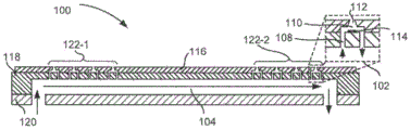
Turning now to the drawings, fig. 1A-1D are views of a fluid-ejecting die (100) having closed lateral channels (104) according to one example of the principles described herein. Specifically, fig. 1A is an isometric view of a fluid ejection die (100). As described above, a fluid-ejecting die (100) refers to a component of a printing system for depositing printing fluid onto a substrate. To eject printing fluid onto a substrate, a fluid-ejecting die (100) includes an array of nozzles (102). For simplicity in fig. 1A, one nozzle (102) has been labeled with a reference numeral. Further, it should be noted that the relative sizes of the nozzle (102) and the fluid-ejecting die (100) are not drawn to scale, with the nozzle being exaggerated for purposes of illustration.
The nozzles (102) of the fluid-ejecting dies (100) may be arranged in a column or array such that properly sequenced ejection of fluid from the nozzles (102) causes characters, symbols, and/or other graphics or images to be printed upon the print medium as the fluid-ejecting dies (100) and the print medium are moved relative to each other.
In one example, the nozzles (102) in the array may be further grouped. For example, a first subset of nozzles (102) in an array may be slaved to one ink color, or one type of fluid having one set of fluid properties, while a second subset of nozzles (102) in an array may be slaved to another ink color, or a fluid having a different set of fluid properties.
The fluid-ejection die (100) may be coupled to a controller that controls the fluid-ejection die (100) when ejecting fluid from the nozzle (102). For example, the controller defines a pattern of ejected fluid drops that form characters, symbols, and/or other graphics or images on the print medium. The pattern of ejected fluid drops is determined by print job commands and/or command parameters received from a computing device.
Fig. 1B and 1C are cross-sectional views of a fluid ejection die (100). More specifically, fig. 1B and 1C are sectional views taken along line a-a in fig. 1A. Fig. 1B and 1C each illustrate a particular type of closed transverse channel (104). Note that in fig. 1B and 1C, reference numeral 104 denotes a closed lateral channel instead of a fluid flow, which is indicated by an arrow.
Fig. 1B and 1C depict, among other things, nozzles (102) in an array. For simplicity, one nozzle (102) in fig. 1B and 1C is depicted with a reference numeral. For ejecting the fluid, the nozzle (102) comprises several components. For example, the nozzle (102) comprises: an ejection chamber (110) holding a quantity of fluid to be ejected; an opening (112) through which the quantity of fluid is ejected; and an ejection fluid actuator (114) disposed within the ejection chamber (110) to eject the quantity of fluid through the opening (112). The ejection chamber (110) and the nozzle opening (112) may be defined in a nozzle substrate (116), the nozzle substrate (116) being placed on top of a channel substrate (118). In some examples, the nozzle base plate (116) is formed of SU-8 or other material.
Turning to ejection actuators (114), ejection fluid actuators (114) may include firing resistors or other thermal devices, piezoelectric elements, or other mechanisms for ejecting fluid from ejection chambers (110). For example, the injector (114) may be a firing resistor. The firing resistor heats in response to an applied voltage. As the firing resistor heats up, a portion of the fluid in the ejection chamber (110) evaporates to form a bubble. The bubble pushes fluid out of the opening (112) and onto the print media. Upon bursting of the vaporized fluid bubble, fluid is drawn from the passageway (108) into the ejection chamber (110), and the process repeats. In this example, the fluid-ejecting die (100) may be a Thermal Inkjet (TIJ) fluid-ejecting die (100).
In another example, the jetting fluid actuator (114) can be a piezoelectric device. Upon application of a voltage, the piezoelectric device changes shape, which generates a pressure pulse in the ejection chamber (110) that pushes fluid out of the opening (112) and onto the print medium. In this example, the fluid-ejection die (100) may be a Piezoelectric Inkjet (PIJ) fluid-ejection die (100).
The fluid ejection die (100) also includes an array of vias (108) formed in the channel substrate (118). The passages (108) convey fluid to and from the respective ejection chambers (110). In some examples, the vias (108) are formed in a perforated film of the channel substrate (118). For example, the channel substrate (118) may be formed of silicon, and the via (108) may be formed in a perforated silicon film forming a portion of the channel substrate (118). That is, the membrane may be perforated with holes that align with the ejection chamber (110) when coupled with the nozzle substrate (116) to form a path for fluid to and from during the ejection process. As depicted in fig. 1B and 1C, there may be two passageways (108) per ejection chamber (110), such that one passageway (108) of the pair is an inlet of the ejection chamber (110) and the other passageway (108) is an outlet of the ejection chamber (110). In some examples, the passages may be round holes, square holes with rounded corners, or other types of passages.
The fluid-ejecting die (100) also includes an array of enclosed lateral channels (104). A closed lateral channel (104) is formed on the back side of the channel substrate (118) and carries fluid to and from the passage (108). In one example, each enclosed transverse channel (104) is fluidly connected to a respective plurality of passageways (108) in an array of passageways (108). That is, fluid enters the closed transverse channel (104), passes through the closed transverse channel (104), passes to the corresponding passageway (108), and subsequently exits the closed transverse channel (104) to mix with other fluids in the associated fluid delivery system. In some examples, the fluid path through the closed lateral channel (104) is perpendicular to the flow through the passageway (108), as indicated by the arrows. That is, fluid enters the inlet, passes through the closed lateral channel (104), passes to the corresponding passageway (108), and then exits the outlet to mix with other fluids in the associated fluid delivery system. The flow through the inlet, closed transverse channel (104) and outlet is indicated by arrows in fig. 1B and 1C.
The closed transverse channel (104) is defined by any number of surfaces. For example, one surface of the closed lateral channel (104) is defined by a membrane portion of a channel substrate (118) in which the passage (108) is formed. The other surface is defined by the cover substrate (120) and the other surface is defined by ribs, as shown in fig. 1D.
Each lateral channel (104) in the array may correspond to a particular row of passageways (108) and a corresponding ejection chamber (110). For example, as depicted in fig. 1A, an array of nozzles (102) may be arranged in rows, and each transverse channel (104) may be aligned with a row such that nozzles (102) in a row share the same transverse channel (104). Although fig. 1A depicts rows of nozzles (102) in line, the rows of nozzles (102) may be angled, curved, V-shaped, or otherwise oriented. Thus, in these examples, the closed lateral channel (104) may be similarly angled, curved, V-shaped, or otherwise oriented to align with the arrangement of nozzles (102). In another example, a particular row of passages (108) may correspond to a plurality of transverse channels (104). That is, the rows may be straight, but the enclosed transverse channels (104) may be angled. Although specific reference is made to one closed cross-channel (104) per row of nozzles (102), in some examples, multiple rows of nozzles (102) may correspond to a single closed cross-channel (104).
In some examples, the closed lateral channels (104) deliver fluid to each row of a different subset of the array of passageways (108). For example, as depicted in fig. 1C, a single closed cross channel (104) may deliver fluid to one row of nozzles (102) in the first subset (122-1) and one row of nozzles (102) in the second subset (122-2). In this example, one type of fluid, e.g., one ink color, may be provided to different subsets (122). In a particular example, a single color fluid ejection die (100) may implement one closed lateral channel (104) that spans multiple subsets (122) of nozzles (102).
In some examples, the closed lateral channels (104) deliver fluid to each row of a single subset (122) of the array of passageways (108). For example, as depicted in FIG. 1B, a first transverse channel (104-1) delivers fluid to a row of nozzles (102) in a first subset (122-1), and a second transverse channel (104-2) delivers fluid to a row of nozzles (102) in a second subset (122-2). In this example, different types of fluids, e.g., different ink colors, may be provided to different subsets (122). Such a fluid-ejecting die (100) may be used in a multi-color printing fluid cartridge.
These closed lateral channels (104) facilitate increased fluid flow through the fluid ejection die (100). For example, without the enclosed lateral channels (104), fluid passing on the back side of the fluid-ejection die (100) may not pass close enough to the passages (108) to be adequately mixed with fluid passing through the nozzles (102). However, the closed lateral channel (104) draws fluid closer to the nozzle (102), thereby facilitating more fluid mixing. The increased fluid flow also improves nozzle health because used fluid is removed from the nozzle (102), which may damage the nozzle (102) if recirculated throughout the nozzle (102).
Fig. 1D is a cross-sectional view of the fluid ejection die (100). More specifically, FIG. 1D is a cross-sectional view taken along line B-B in FIG. 1A. Fig. 1D depicts several closed lateral channels (104) along the length of the fluid-ejecting die (100). Although fig. 1D depicts a number of closed lateral channels (104), the fluid-ejecting die (100) may include any number of these closed lateral channels (104).
Fig. 1D also depicts a passageway (108) through which fluid passes to the ejection chamber (110). For the sake of brevity, a single instance of the passageway (108) and the enclosed transverse channel (104) are depicted with reference numerals. Although fig. 1D illustrates the ribs partially defining the closed lateral channels (104) as being formed by the channel substrate (118), in some examples, the closed lateral channels may be formed by a cover substrate (120), which cover substrate (120) may be formed of glass, silicon, or other material.
Fig. 2 is a cross-sectional view of a fluid ejection die (fig. 1, 100) having closed lateral channels (104) according to one example of principles described herein. Specifically, fig. 2 depicts the portion of the enclosed transverse channel (104) that passes under the single pass (108). Note that the elements depicted in fig. 2 are not drawn to scale and are exaggerated for illustrative purposes. Fig. 2 clearly depicts fluid flow through the closed transverse channel (104) and the passageway (108). As depicted, the fluid flow is vertical. That is, as the fluid flows through the closed lateral channel (104), it changes direction vertically as it passes through the passageway (108) to be directed to the nozzle (fig. 1, 102).
In some examples, each nozzle (fig. 1, 102) may include a channel (221-1, 221-2) in addition to the ejection fluid actuator (fig. 1, 114), the ejection chamber (110-1, 110-2), and the opening (112-1, 112-2) to direct fluid to and from the corresponding ejection chamber (110). Such channels (221) may have dimensions (e.g., nanoscale, microscale, millimeter-scale, etc.) small enough to facilitate the transport of small amounts of fluids (e.g., pico-upgrades, nano-upgrades, micro-upgrades, nano-upgrades, etc.). In this example, the channels (221-1, 221-2) and passages (108) corresponding to the nozzles (fig. 1, 102) form a micro-recirculation loop. In some examples, a pump fluid actuator is disposed within the channel (221) to shuttle fluid to and from the ejection chamber (110). Such microchannels (221-1, 221-2) prevent fluid passing therethrough from settling and ensure that fresh fluid is available for ejection through the opening (112). The fluid actuators, i.e., both the ejector (114, fig. 1) and the pump actuator, may be electrostatic membrane actuators, mechanical/impact driven membrane actuators, magnetostrictive driven actuators, or other such elements that can displace fluid in response to electrical actuation.
As described above, such a micro-recirculation loop provides fresh fluid to the ejection chamber (110), thereby increasing the useful life of the nozzle (fig. 1, 102). This is because the nozzle (fig. 1, 102) operates optimally when supplied with fresh fluid.
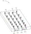
Fig. 3 is an isometric view of the underside of a fluid ejection die (100) having closed lateral channels (104-1, 104-2) according to one example of the principles described herein. For the sake of brevity, a few examples of closed transverse channels (104-1, 104-2) and associated ribs (324-1, 324-2) are labeled with reference numerals.
Fig. 3 clearly depicts the fluid flow path through the fluid ejection die (100), particularly through the closed lateral channels (104). In the example depicted in fig. 3, the array of nozzles (fig. 1, 102) may be divided into two subsets (fig. 2, 221-1, 221-2), however, the array of nozzles (fig. 1, 102) may be divided into any number of subsets (fig. 2, 221).
In this example, the fluid enters an inlet, which may be common to several closed transverse channels (104). The fluid then enters the closed lateral channel (104), the closed lateral channel (104) being defined in part by the ribs (324-1 ) and the cover substrate (120). As the fluid flows through the closed cross channel (104), it is directed through the passageway (fig. 1, 108) and the nozzle (fig. 1, 102), which may include a micro-recirculation loop (fig. 1, 102). The excess fluid is then transferred back to the closed lateral channel (104), where it is discharged out of the outlet of the closed lateral channel (104).
Fig. 4 is a block diagram of a printing-fluid cartridge (426) including a fluid-ejecting die (100) with closed lateral channels (fig. 1, 104) according to one example of principles described herein. A print fluid cartridge (426) is within the printing system for ejecting fluid. In some examples, the printing-fluid cartridge (426) is removable from the system, for example as a replaceable cartridge (426). In some examples, the printing-fluid cartridge (426) is a substrate-wide print bar, and the array of fluid-ejecting dies (100) is grouped into printheads that are staggered across the width of the substrate on which fluid is to be deposited. An example of such a printhead is depicted in fig. 6.
The printing fluid cartridge (426) includes a housing (428) to house components of the printing fluid cartridge (426). The housing (428) houses a fluid reservoir (430) to supply an amount of fluid to the fluid-ejecting die (100). Generally, fluid flows between the reservoir (430) and the fluid-ejecting die (100). In some examples, a portion of the fluid supplied to the fluid-ejection die (100) is consumed during operation, while fluid not consumed during printing is returned to the fluid reservoir (430). In some examples, the fluid may be ink. In one particular example, the ink may be a water-based Ultraviolet (UV) ink, a pharmaceutical fluid, or a 3D printing material, among other fluids.
Fig. 5 is a block diagram of a printing device (532) including several fluid ejection dies (100-1, 100-2, 100-3, 100-4) with enclosed lateral channels (fig. 1, 104) in a substrate wide printbar (534), according to one example of principles described herein. The printing device (532) may include a print bar (534) spanning the width of a print substrate (536), a number of flow regulators (538) associated with the print bar (534), a substrate transport mechanism (540), a printing fluid supply (542), such as a fluid reservoir (430, fig. 4), and a controller (544). The controller (544) represents programming, a processor and associated memory, along with other electronic circuitry and components that control the operative elements of the printing apparatus (532). The printbar (534) can include an arrangement of fluid-ejecting dies (100) for dispensing fluid onto a sheet or continuous web of paper or other print substrate (536). Each fluid ejecting die (100) receives fluid through a flow path that is: the flow path extends from the fluid supply (542) into and through the flow regulator (538) and through a number of transfer molding fluid channels (546) defined in the printbar (534).
Fig. 6 is a block diagram of a printbar (534) including several fluid-ejecting dies (100) with enclosed lateral channels (fig. 1, 104) according to one example of principles described herein. In some examples, the fluid ejection die (100) are embedded in an elongated, single-piece molding (650) and arranged end-to-end in rows (648). The fluid-ejection dies (100) are arranged in a staggered configuration, with the fluid-ejection dies (100) in each row (648) overlapping another fluid-ejection die (100) in the same row (648). In this arrangement, each row (648) of fluid ejection dies (100) receives fluid from a different transfer mold fluid channel (652), as shown with dashed lines in fig. 6. Although fig. 6 depicts four fluid channels (652) that supply four rows (648) of interleaved fluid ejection dies (100), for example, when printing four different colors, such as cyan, magenta, yellow, and black, other suitable configurations are possible.
Fig. 7 is a flow chart of a method (700) for forming a fluid ejection die (fig. 1, 100) having closed lateral channels (fig. 1, 104) according to one example of principles described herein. According to the method (700), an array of nozzles (fig. 1, 102) and vias (fig. 1, 108) is formed (block 701). In some examples, the via (fig. 1, 108) may be part of a perforated silicon film. The nozzle (fig. 1, 102), and more specifically the opening (fig. 1, 112) of the nozzle (fig. 1, 102) and the ejection chamber (fig. 1, 110), may be formed from a nozzle substrate (fig. 1, 116) such as SU-8. Thus, forming (block 701) an array of nozzles (fig. 1, 102) and vias (fig. 1, 108) may include coupling the perforated silicon membrane with an SU-8 nozzle substrate (fig. 1, 116).
Then, a closed lateral channel (fig. 1, 104) is formed (block 702). Forming (block 702) the enclosed lateral channel (fig. 1, 104) may include adhering a rib (fig. 3, 324) to a back side of the membrane having the via (fig. 1, 108) formed therein, and attaching a cover substrate (fig. 1, 120). In another example, the forming (block 702) may include etching away the channel substrate (fig. 1, 118) to form ribs (fig. 3, 324) that partially define the enclosed lateral channels (fig. 1, 104).
Where a closed lateral channel (fig. 1, 104) is formed and a nozzle (fig. 1, 102) and a passageway (fig. 1, 108) are formed, the two are coupled (block 703) to form a fluid-ejecting die (fig. 1, 100) having a closed lateral channel (fig. 1, 104). Fig. 8A-10D depict various examples of fabricating a fluid ejection die (fig. 1, 104).
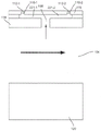
Fig. 8A-8D depict a method of fabricating a fluid ejection die (fig. 1, 100) having closed lateral channels (fig. 1, 104) according to one example of principles described herein. For purposes of clarity, within a given figure, one instance of each component is labeled with a reference numeral, but multiple instances of those components may be illustrated.
First, in fig. 8A, a nozzle opening (112) and an ejection chamber (110) are formed in a nozzle substrate (116) that may be formed of a material such as SU-8. Forming the opening (112) and the ejection chamber (110) in the nozzle substrate (116) may be by etching or photolithography. The nozzle substrate (116) with the openings (112) and ejection chambers (110) formed therein is then coupled to the layer (854) with the vias (108) formed therein. Such a layer (854) may be a thin silicon film with perforations that define the vias (108). In this example, the via (108) may be formed to a predetermined depth and the layer (854) thinned until the via (108) is exposed.
Next, in fig. 8B, ribs (324) may be formed that define channels (fig. 1, 104). In some examples, this may include etching a portion of the silicon substrate to define closed lateral channels (fig. 1, 104), and further etching or laser ablating other portions of the substrate to define inlet and outlet slots.
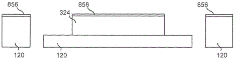
Then, as depicted in fig. 8C, adhesive (856) is placed on the lid substrate (120) and ribs (324), and the structure including nozzles (fig. 1, 102) and vias (108) is coupled to the ribs (324)/lid substrate (120), as depicted in fig. 8D. The fluid then flows through the inlet in the closed lateral channel (fig. 1, 104), past the ribs (324), into the corresponding passageway (108), and out the outlet.
Fig. 9A-9D depict a method of fabricating a fluid ejection die (fig. 1, 100) having closed lateral channels (fig. 1, 104) according to another example of principles described herein. In this example, a nozzle substrate (116) defining an ejection chamber (110) and a nozzle opening (112) is adhered to a substrate (854), such as a silicon film perforated to define a passageway (108). In this example, a layer (958) of silicon dioxide or another insulator may be embedded in the substrate (854). Thus, in this example, the via (108) may be formed in the substrate (854) by performing a Deep Reactive Ion Etch (DRIE) on the substrate (854) that will form the via (108) to the insulator material layer (958). Fig. 9A also depicts a portion of a first of two etching operations for forming closed-ended lateral channels (fig. 1, 104). In this first part of the first etching operation, a photoresist is laid down that defines closed lateral channels (fig. 1, 104) that include ribs (324). A first etching operation is performed on the silicon material to define ribs (324), the ribs (324) defining closed lateral channels (fig. 1, 104).
Fig. 9B depicts a second portion of the first etch operation and a second etch operation. In a second part of the first etch operation, the photoresist is removed, leaving a second masking layer defining windows around the ribs (324). The substrate (854) is further etched to continue defining the ribs (324) with 1) and forming windows around the ribs (324). Finally, during a third etch operation, portions of the insulator layer (958) are removed to expose the vias (108) to the closed lateral channels (fig. 1, 104).
In fig. 9C, adhesive (960) is disposed on top of the ribs (324), and the ribs (324) are adhered to the cover substrate (120) to form closed transverse channels (fig. 1, 104), as depicted in fig. 9D. The fluid then flows through the inlet in the closed lateral channel (fig. 1, 104), past the ribs (324), into the corresponding passageway (108), and out the outlet.
Fig. 10A-10D depict a method of fabricating a fluid ejection die having closed lateral channels according to another example of principles described herein. In fig. 10A, a nozzle substrate (116) defining an ejection chamber (110) and nozzle opening (112) is adhered to a substrate (854), such as a silicon film perforated to define a via (108), the substrate (854) having an embedded insulator layer (958), as described above with respect to fig. 9A-9D. In this example, the substrate (854) is thinned and a first etching operation is performed on the silicon material using photoresist to define ribs (324), the ribs (324) defining closed lateral channels (104, fig. 1). A second etch operation is then performed to etch away the insulator layer 958 to expose the vias 108.
In FIG. 10B, a cover substrate (120) having inlet and outlet slots is formed by: the substrate is thinned by etching or laser ablation of the grooves followed by wafer thinning using a wafer grinding operation. In fig. 10C, adhesive (960) is disposed on top of the ribs (324), and the cover substrate (120) is adhered to the ribs (324) to form closed transverse channels (fig. 1, 104), as depicted in fig. 10D. The fluid then flows through the inlet in the closed lateral channel (fig. 1, 104), past the ribs (324), into the corresponding passageway (108), and out the outlet.
In summary, using such a fluid ejection die: 1) reducing the likelihood of decap by maintaining water concentration in the fluid; 2) facilitating more efficient micro-recirculation within the nozzle; 3) the nozzle health is improved; 4) providing fluid mixing near the die to improve print quality; 5) convectively cooling the fluid ejection die; 6) removing bubbles from the fluid-ejecting die; and 7) allowing the nozzle to be refilled. However, it is contemplated that the devices disclosed herein may address other problems and deficiencies in many areas of technology.
The foregoing description has been presented to illustrate and describe examples of the principles described. This description is not intended to be exhaustive or to limit these principles to any precise form disclosed. Many modifications and variations are possible in light of the above teaching.
Claims (15)
1. A fluid ejection die, comprising:
an array of nozzles, each nozzle comprising:
an ejection chamber;
an opening; and
a fluid actuator disposed within the ejection chamber;
an array of passages formed in the substrate to transport fluid to and from the ejection chambers; and
an array of closed lateral channels formed on the rear surface of the substrate, each closed lateral channel in the array being fluidly connected to a respective plurality of the array of passageways.
2. The fluid ejection die of claim 1, wherein the via is formed in a perforated layer of the substrate.
3. The fluid ejection die of claim 1, wherein the closed lateral channels deliver fluid to rows of different sub-arrays of the vias.
4. The fluid ejection die of claim 1, wherein the array of closed lateral channels are grouped into sub-arrays, each sub-array of closed lateral channels delivering fluid to a respective row of the sub-array of the array of passages.
5. The fluid ejection die of claim 4, wherein different sub-arrays of vias correspond to different colors of fluid.
6. The fluid ejection die of claim 1, wherein:
each nozzle further comprises a channel directing fluid to and from a corresponding ejection chamber; and
the channels and the passages corresponding to the nozzles form a micro-recirculation loop.
7. The fluid ejection die of claim 1, wherein the channels of a row correspond to the same closed lateral channel.
8. The fluid ejection die of claim 1, wherein the channels of a row correspond to a plurality of closed lateral channels.
9. The fluid ejection die of claim 1, wherein fluid flow through the closed lateral channel is perpendicular to fluid flow in the via.
10. A printing-fluid cartridge comprising:
a housing;
a reservoir disposed within the housing to contain a fluid to be deposited on a substrate; and
an array of fluid ejection dies disposed on the housing, each fluid ejection die comprising:
an array of nozzles, each nozzle comprising:
an ejection chamber;
an opening; and
a fluid actuator disposed within the ejection chamber;
an array of passages that transport fluid to and from the ejection chambers; and
an array of closed lateral channels formed on the rear surface of the substrate, each closed lateral channel in the array of closed lateral channels being fluidly connected to a respective plurality of the array of passageways.
11. The printing-fluid cartridge of claim 10, wherein:
each nozzle further comprises:
channels that direct fluid to and from the corresponding ejection chambers; and
a secondary fluid actuator to move fluid through the channel; and
the channels and the passages corresponding to the nozzles form a micro-recirculation loop of the nozzles.
12. The printing-fluid cartridge of claim 10, wherein:
the printing fluid box is a substrate wide printing rod; and
the array of fluid ejection dies is grouped into printheads, wherein the printheads are staggered across a width of a substrate on which fluid is to be deposited.
13. A method for fabricating a fluid ejection die, comprising:
forming an array of nozzles and corresponding passages through which fluid is ejected;
forming a plurality of closed transverse channels, wherein the plurality of closed transverse channels transport fluid to and from the passageway; and
coupling the array of nozzles and corresponding passageways to the number of closed transverse channels.
14. The method of claim 13, wherein forming the plurality of closed lateral channels on the substrate comprises: etching a rear layer of the substrate on which the via is formed.
15. The method of claim 13, wherein forming the array of nozzles and corresponding vias comprises: adhering a film containing the via to a layer defining the nozzle.
Applications Claiming Priority (1)
| Application Number | Priority Date | Filing Date | Title |
|---|---|---|---|
| PCT/US2017/044738 WO2019027430A1 (en) | 2017-07-31 | 2017-07-31 | Fluidic ejection dies with enclosed cross-channels |
Publications (2)
| Publication Number | Publication Date |
|---|---|
| CN110891793A CN110891793A (en) | 2020-03-17 |
| CN110891793B true CN110891793B (en) | 2021-04-09 |
Family
ID=65232954
Family Applications (1)
| Application Number | Title | Priority Date | Filing Date |
|---|---|---|---|
| CN201780093600.9A Active CN110891793B (en) | 2017-07-31 | 2017-07-31 | Fluid ejection die with enclosed lateral channels |
Country Status (6)
| Country | Link |
|---|---|
| US (2) | US11059291B2 (en) |
| EP (1) | EP3609711A4 (en) |
| JP (1) | JP6967151B2 (en) |
| CN (1) | CN110891793B (en) |
| TW (1) | TWI681880B (en) |
| WO (1) | WO2019027430A1 (en) |
Families Citing this family (3)
| Publication number | Priority date | Publication date | Assignee | Title |
|---|---|---|---|---|
| US11780227B2 (en) | 2019-06-25 | 2023-10-10 | Hewlett-Packard Development Company, L.P. | Molded structures with channels |
| EP3990286A4 (en) * | 2019-06-25 | 2023-04-26 | Hewlett-Packard Development Company, L.P. | Molded structures with channels |
| US11597204B2 (en) * | 2019-06-25 | 2023-03-07 | Hewlett-Packard Development Company, L.P. | Fluid ejection polymeric recirculation channel |
Family Cites Families (48)
| Publication number | Priority date | Publication date | Assignee | Title |
|---|---|---|---|---|
| US7527357B2 (en) * | 1997-07-15 | 2009-05-05 | Silverbrook Research Pty Ltd | Inkjet nozzle array with individual feed channel for each nozzle |
| US6309054B1 (en) | 1998-10-23 | 2001-10-30 | Hewlett-Packard Company | Pillars in a printhead |
| US6244694B1 (en) * | 1999-08-03 | 2001-06-12 | Hewlett-Packard Company | Method and apparatus for dampening vibration in the ink in computer controlled printers |
| US6513896B1 (en) | 2000-03-10 | 2003-02-04 | Hewlett-Packard Company | Methods of fabricating fit firing chambers of different drop weights on a single printhead |
| JP4875997B2 (en) | 2007-02-16 | 2012-02-15 | 富士フイルム株式会社 | Liquid discharge head and liquid discharge apparatus |
| JP5593616B2 (en) | 2008-02-26 | 2014-09-24 | 株式会社リコー | Liquid ejection head and image forming apparatus |
| US8109607B2 (en) | 2008-03-10 | 2012-02-07 | Hewlett-Packard Development Company, L.P. | Fluid ejector structure and fabrication method |
| BRPI0912897A2 (en) | 2008-05-23 | 2015-10-06 | Fujifilm Corp | fluid droplet ejection |
| US8651624B2 (en) | 2008-10-14 | 2014-02-18 | Hewlett-Packard Development Company, L.P. | Fluid ejector structure |
| JP5375669B2 (en) | 2009-06-29 | 2013-12-25 | 株式会社リコー | Liquid ejection head, liquid droplet ejection apparatus, and image forming apparatus |
| US8240796B2 (en) | 2009-07-09 | 2012-08-14 | Fujifilm Corporation | Fluid ejector housing insert |
| JP5328542B2 (en) * | 2009-07-27 | 2013-10-30 | キヤノン株式会社 | Recording element substrate, ink jet head, and manufacturing method thereof |
| US8287094B2 (en) | 2009-07-27 | 2012-10-16 | Zamtec Limited | Printhead integrated circuit configured for backside electrical connection |
| US8496317B2 (en) | 2009-08-11 | 2013-07-30 | Eastman Kodak Company | Metalized printhead substrate overmolded with plastic |
| JP5777706B2 (en) * | 2010-05-21 | 2015-09-09 | ヒューレット−パッカード デベロップメント カンパニー エル.ピー.Hewlett‐Packard Development Company, L.P. | Fluid ejecting apparatus having circulation pump |
| US8205965B2 (en) | 2010-07-20 | 2012-06-26 | Hewlett-Packard Development Company, L.P. | Print bar structure |
| CN103025530B (en) * | 2010-07-28 | 2015-06-10 | 惠普发展公司,有限责任合伙企业 | Fluid ejection assembly with circulation pump |
| US8657420B2 (en) | 2010-12-28 | 2014-02-25 | Fujifilm Corporation | Fluid recirculation in droplet ejection devices |
| US8438730B2 (en) * | 2011-01-26 | 2013-05-14 | Eastman Kodak Company | Method of protecting printhead die face |
| US8449086B2 (en) | 2011-03-30 | 2013-05-28 | Eastman Kodak Company | Inkjet chamber and inlets for circulating flow |
| US9221247B2 (en) | 2011-06-29 | 2015-12-29 | Hewlett-Packard Development Company, L.P. | Piezoelectric inkjet die stack |
| KR20140048159A (en) | 2011-06-29 | 2014-04-23 | 휴렛-팩커드 디벨롭먼트 컴퍼니, 엘.피. | Piezoelectric printhead trace layout |
| US8382253B1 (en) | 2011-08-25 | 2013-02-26 | Hewlett-Packard Development Company, L.P. | Fluid ejection device and methods of fabrication |
| JP5728622B2 (en) * | 2011-09-28 | 2015-06-03 | ヒューレット−パッカード デベロップメント カンパニー エル.ピー.Hewlett‐Packard Development Company, L.P. | Circulation between slots in fluid ejection devices |
| US8814293B2 (en) | 2012-01-13 | 2014-08-26 | Lexmark International, Inc. | On-chip fluid recirculation pump for micro-fluid applications |
| WO2013165373A1 (en) | 2012-04-30 | 2013-11-07 | Hewlett-Packard Development Company, L.P. | Flexible substrate with integrated circuit |
| US8672463B2 (en) | 2012-05-01 | 2014-03-18 | Fujifilm Corporation | Bypass fluid circulation in fluid ejection devices |
| US9597873B2 (en) | 2012-09-12 | 2017-03-21 | Hewlett-Packard Development Company, L.P. | Printhead protective coating |
| JP6090560B2 (en) | 2012-10-12 | 2017-03-08 | セイコーエプソン株式会社 | Liquid ejector |
| US11426900B2 (en) | 2013-02-28 | 2022-08-30 | Hewlett-Packard Development Company, L.P. | Molding a fluid flow structure |
| US9517626B2 (en) | 2013-02-28 | 2016-12-13 | Hewlett-Packard Development Company, L.P. | Printed circuit board fluid ejection apparatus |
| EP3296113B1 (en) | 2013-02-28 | 2019-08-28 | Hewlett-Packard Development Company, L.P. | Molded print bar |
| CN105555539B (en) | 2013-09-20 | 2017-08-15 | 惠普发展公司,有限责任合伙企业 | Print bar and the method for forming print bar |
| WO2015080730A1 (en) | 2013-11-27 | 2015-06-04 | Hewlett-Packard Development Company, L.P. | Printhead with bond pad surrounded by dam |
| US10421274B2 (en) | 2014-01-28 | 2019-09-24 | Hewlett-Packard Devleopment Company. L.P. | Printbars and methods of forming printbars |
| KR102247763B1 (en) | 2014-04-24 | 2021-05-03 | 휴렛-팩커드 디벨롭먼트 컴퍼니, 엘.피. | Overmolded ink delivery device |
| KR20170105108A (en) | 2015-02-27 | 2017-09-18 | 휴렛-팩커드 디벨롭먼트 컴퍼니, 엘.피. | Fluid ejection device with fluid feed hole |
| JP6536130B2 (en) | 2015-03-31 | 2019-07-03 | ブラザー工業株式会社 | Liquid discharge head and liquid discharge device |
| US10479081B2 (en) | 2015-10-12 | 2019-11-19 | Hewlett-Packard Development Company, L.P. | Printhead with flexible substrate |
| CN107949481B (en) | 2015-10-12 | 2021-01-05 | 惠普发展公司,有限责任合伙企业 | Printing head |
| WO2017074354A1 (en) | 2015-10-28 | 2017-05-04 | Hewlett-Packard Development Company, L.P. | Printer cartridge with multiple backpressure chambers |
| CN108367569B (en) | 2015-12-11 | 2020-06-16 | 柯尼卡美能达株式会社 | Ink jet head and ink jet recording apparatus |
| JP6716258B2 (en) * | 2016-01-08 | 2020-07-01 | キヤノン株式会社 | Recording device, recording device control method, and program |
| JP6987497B2 (en) | 2016-01-08 | 2022-01-05 | キヤノン株式会社 | Liquid discharge module and liquid discharge head |
| JP7013124B2 (en) * | 2016-01-08 | 2022-01-31 | キヤノン株式会社 | Manufacturing method of liquid discharge head |
| CN110891792B (en) * | 2017-07-31 | 2021-06-01 | 惠普发展公司,有限责任合伙企业 | Fluid ejection device with enclosed lateral channels |
| CN111372782B (en) * | 2017-11-27 | 2021-10-29 | 惠普发展公司,有限责任合伙企业 | Cross-die recirculation channel and chamber recirculation channel |
| WO2019108235A1 (en) * | 2017-12-02 | 2019-06-06 | Hewlett-Packard Development Company, L.P. | Fluid circulation and ejection |
-
2017
- 2017-07-31 US US16/629,366 patent/US11059291B2/en active Active
- 2017-07-31 WO PCT/US2017/044738 patent/WO2019027430A1/en unknown
- 2017-07-31 CN CN201780093600.9A patent/CN110891793B/en active Active
- 2017-07-31 JP JP2020527725A patent/JP6967151B2/en active Active
- 2017-07-31 EP EP17919812.2A patent/EP3609711A4/en active Pending
-
2018
- 2018-07-23 TW TW107125342A patent/TWI681880B/en not_active IP Right Cessation
-
2021
- 2021-06-07 US US17/340,570 patent/US11654680B2/en active Active
Also Published As
| Publication number | Publication date |
|---|---|
| US11059291B2 (en) | 2021-07-13 |
| EP3609711A1 (en) | 2020-02-19 |
| JP6967151B2 (en) | 2021-11-17 |
| US11654680B2 (en) | 2023-05-23 |
| US20210129534A1 (en) | 2021-05-06 |
| CN110891793A (en) | 2020-03-17 |
| WO2019027430A1 (en) | 2019-02-07 |
| TW201910143A (en) | 2019-03-16 |
| TWI681880B (en) | 2020-01-11 |
| JP2020528844A (en) | 2020-10-01 |
| EP3609711A4 (en) | 2020-11-11 |
| US20210291547A1 (en) | 2021-09-23 |
Similar Documents
| Publication | Publication Date | Title |
|---|---|---|
| CN110891792B (en) | Fluid ejection device with enclosed lateral channels | |
| US11654680B2 (en) | Fluidic ejection dies with enclosed cross-channels | |
| CN111212737B (en) | Fluid chip | |
| EP3212409A1 (en) | Fluid ejection device | |
| US11565521B2 (en) | Fluid ejection device with a portioning wall | |
| TWI715867B (en) | Fluidic ejection die and method for making the same, and printing fluid cartridge | |
| CN111032359B (en) | Fluidic sheet, system for circulating fluid within fluidic sheet, and fluid flow structure |
Legal Events
| Date | Code | Title | Description |
|---|---|---|---|
| PB01 | Publication | ||
| PB01 | Publication | ||
| SE01 | Entry into force of request for substantive examination | ||
| SE01 | Entry into force of request for substantive examination | ||
| GR01 | Patent grant | ||
| GR01 | Patent grant |