JP5728622B2 - Circulation between slots in fluid ejection devices - Google Patents
Circulation between slots in fluid ejection devices Download PDFInfo
- Publication number
- JP5728622B2 JP5728622B2 JP2014533251A JP2014533251A JP5728622B2 JP 5728622 B2 JP5728622 B2 JP 5728622B2 JP 2014533251 A JP2014533251 A JP 2014533251A JP 2014533251 A JP2014533251 A JP 2014533251A JP 5728622 B2 JP5728622 B2 JP 5728622B2
- Authority
- JP
- Japan
- Prior art keywords
- fluid
- slot
- channel
- chamber
- slots
- Prior art date
- Legal status (The legal status is an assumption and is not a legal conclusion. Google has not performed a legal analysis and makes no representation as to the accuracy of the status listed.)
- Expired - Fee Related
Links
- 239000012530 fluid Substances 0.000 title claims description 384
- 239000000758 substrate Substances 0.000 claims description 38
- 238000006073 displacement reaction Methods 0.000 claims description 37
- 238000005086 pumping Methods 0.000 claims description 24
- 238000000034 method Methods 0.000 claims description 16
- 238000004891 communication Methods 0.000 claims description 10
- 230000002093 peripheral effect Effects 0.000 claims description 9
- 230000006835 compression Effects 0.000 claims description 8
- 238000007906 compression Methods 0.000 claims description 8
- 230000008878 coupling Effects 0.000 claims 3
- 238000010168 coupling process Methods 0.000 claims 3
- 238000005859 coupling reaction Methods 0.000 claims 3
- 239000000976 ink Substances 0.000 description 77
- 238000007641 inkjet printing Methods 0.000 description 14
- 239000000049 pigment Substances 0.000 description 12
- 239000002245 particle Substances 0.000 description 6
- 239000001042 pigment based ink Substances 0.000 description 6
- 238000007639 printing Methods 0.000 description 6
- 230000015572 biosynthetic process Effects 0.000 description 5
- 238000010304 firing Methods 0.000 description 5
- 239000000463 material Substances 0.000 description 5
- 235000001892 vitamin D2 Nutrition 0.000 description 5
- XLYOFNOQVPJJNP-UHFFFAOYSA-N water Substances O XLYOFNOQVPJJNP-UHFFFAOYSA-N 0.000 description 5
- 238000003860 storage Methods 0.000 description 4
- 230000000694 effects Effects 0.000 description 3
- 239000010408 film Substances 0.000 description 3
- 230000007246 mechanism Effects 0.000 description 3
- 229910052751 metal Inorganic materials 0.000 description 3
- 239000002184 metal Substances 0.000 description 3
- PXHVJJICTQNCMI-UHFFFAOYSA-N Nickel Chemical compound [Ni] PXHVJJICTQNCMI-UHFFFAOYSA-N 0.000 description 2
- KDLHZDBZIXYQEI-UHFFFAOYSA-N Palladium Chemical compound [Pd] KDLHZDBZIXYQEI-UHFFFAOYSA-N 0.000 description 2
- 238000009825 accumulation Methods 0.000 description 2
- 230000004913 activation Effects 0.000 description 2
- 238000003491 array Methods 0.000 description 2
- 230000015556 catabolic process Effects 0.000 description 2
- 238000006731 degradation reaction Methods 0.000 description 2
- 238000010586 diagram Methods 0.000 description 2
- 239000002270 dispersing agent Substances 0.000 description 2
- -1 for example Polymers 0.000 description 2
- 230000033001 locomotion Effects 0.000 description 2
- 230000007774 longterm Effects 0.000 description 2
- 238000012423 maintenance Methods 0.000 description 2
- 150000002739 metals Chemical class 0.000 description 2
- 238000001556 precipitation Methods 0.000 description 2
- 230000003134 recirculating effect Effects 0.000 description 2
- 238000000935 solvent evaporation Methods 0.000 description 2
- 229920002799 BoPET Polymers 0.000 description 1
- 239000004642 Polyimide Substances 0.000 description 1
- XUIMIQQOPSSXEZ-UHFFFAOYSA-N Silicon Chemical compound [Si] XUIMIQQOPSSXEZ-UHFFFAOYSA-N 0.000 description 1
- 230000003213 activating effect Effects 0.000 description 1
- 230000002411 adverse Effects 0.000 description 1
- 230000002776 aggregation Effects 0.000 description 1
- 238000004220 aggregation Methods 0.000 description 1
- 230000005540 biological transmission Effects 0.000 description 1
- 230000000903 blocking effect Effects 0.000 description 1
- 230000008859 change Effects 0.000 description 1
- 238000011161 development Methods 0.000 description 1
- 230000007613 environmental effect Effects 0.000 description 1
- 238000001704 evaporation Methods 0.000 description 1
- 230000008020 evaporation Effects 0.000 description 1
- 230000006870 function Effects 0.000 description 1
- 230000008571 general function Effects 0.000 description 1
- 230000005484 gravity Effects 0.000 description 1
- 238000010438 heat treatment Methods 0.000 description 1
- 230000006872 improvement Effects 0.000 description 1
- 239000007788 liquid Substances 0.000 description 1
- 238000004519 manufacturing process Methods 0.000 description 1
- 239000012528 membrane Substances 0.000 description 1
- 229910052759 nickel Inorganic materials 0.000 description 1
- 229910052763 palladium Inorganic materials 0.000 description 1
- 238000002161 passivation Methods 0.000 description 1
- 229920001721 polyimide Polymers 0.000 description 1
- 229920000642 polymer Polymers 0.000 description 1
- 238000000926 separation method Methods 0.000 description 1
- 229910052710 silicon Inorganic materials 0.000 description 1
- 239000010703 silicon Substances 0.000 description 1
- 238000002791 soaking Methods 0.000 description 1
- 229910001220 stainless steel Inorganic materials 0.000 description 1
- 239000010935 stainless steel Substances 0.000 description 1
- 239000010409 thin film Substances 0.000 description 1
- MECHNRXZTMCUDQ-RKHKHRCZSA-N vitamin D2 Chemical compound C1(/[C@@H]2CC[C@@H]([C@]2(CCC1)C)[C@H](C)/C=C/[C@H](C)C(C)C)=C\C=C1\C[C@@H](O)CCC1=C MECHNRXZTMCUDQ-RKHKHRCZSA-N 0.000 description 1
- 239000011653 vitamin D2 Substances 0.000 description 1
Images


Classifications
-
- G—PHYSICS
- G01—MEASURING; TESTING
- G01D—MEASURING NOT SPECIALLY ADAPTED FOR A SPECIFIC VARIABLE; ARRANGEMENTS FOR MEASURING TWO OR MORE VARIABLES NOT COVERED IN A SINGLE OTHER SUBCLASS; TARIFF METERING APPARATUS; MEASURING OR TESTING NOT OTHERWISE PROVIDED FOR
- G01D15/00—Component parts of recorders for measuring arrangements not specially adapted for a specific variable
- G01D15/16—Recording elements transferring recording material, e.g. ink, to the recording surface
- G01D15/18—Nozzles emitting recording material
-
- B—PERFORMING OPERATIONS; TRANSPORTING
- B41—PRINTING; LINING MACHINES; TYPEWRITERS; STAMPS
- B41J—TYPEWRITERS; SELECTIVE PRINTING MECHANISMS, i.e. MECHANISMS PRINTING OTHERWISE THAN FROM A FORME; CORRECTION OF TYPOGRAPHICAL ERRORS
- B41J2/00—Typewriters or selective printing mechanisms characterised by the printing or marking process for which they are designed
- B41J2/005—Typewriters or selective printing mechanisms characterised by the printing or marking process for which they are designed characterised by bringing liquid or particles selectively into contact with a printing material
- B41J2/01—Ink jet
- B41J2/135—Nozzles
- B41J2/14—Structure thereof only for on-demand ink jet heads
- B41J2/14016—Structure of bubble jet print heads
- B41J2/14032—Structure of the pressure chamber
- B41J2/1404—Geometrical characteristics
-
- B—PERFORMING OPERATIONS; TRANSPORTING
- B41—PRINTING; LINING MACHINES; TYPEWRITERS; STAMPS
- B41J—TYPEWRITERS; SELECTIVE PRINTING MECHANISMS, i.e. MECHANISMS PRINTING OTHERWISE THAN FROM A FORME; CORRECTION OF TYPOGRAPHICAL ERRORS
- B41J2/00—Typewriters or selective printing mechanisms characterised by the printing or marking process for which they are designed
- B41J2/005—Typewriters or selective printing mechanisms characterised by the printing or marking process for which they are designed characterised by bringing liquid or particles selectively into contact with a printing material
- B41J2/01—Ink jet
- B41J2/135—Nozzles
- B41J2/14—Structure thereof only for on-demand ink jet heads
- B41J2/14016—Structure of bubble jet print heads
- B41J2/14145—Structure of the manifold
-
- B—PERFORMING OPERATIONS; TRANSPORTING
- B41—PRINTING; LINING MACHINES; TYPEWRITERS; STAMPS
- B41J—TYPEWRITERS; SELECTIVE PRINTING MECHANISMS, i.e. MECHANISMS PRINTING OTHERWISE THAN FROM A FORME; CORRECTION OF TYPOGRAPHICAL ERRORS
- B41J2/00—Typewriters or selective printing mechanisms characterised by the printing or marking process for which they are designed
- B41J2/005—Typewriters or selective printing mechanisms characterised by the printing or marking process for which they are designed characterised by bringing liquid or particles selectively into contact with a printing material
- B41J2/01—Ink jet
- B41J2/135—Nozzles
- B41J2/14—Structure thereof only for on-demand ink jet heads
- B41J2/1433—Structure of nozzle plates
-
- B—PERFORMING OPERATIONS; TRANSPORTING
- B41—PRINTING; LINING MACHINES; TYPEWRITERS; STAMPS
- B41J—TYPEWRITERS; SELECTIVE PRINTING MECHANISMS, i.e. MECHANISMS PRINTING OTHERWISE THAN FROM A FORME; CORRECTION OF TYPOGRAPHICAL ERRORS
- B41J2/00—Typewriters or selective printing mechanisms characterised by the printing or marking process for which they are designed
- B41J2/005—Typewriters or selective printing mechanisms characterised by the printing or marking process for which they are designed characterised by bringing liquid or particles selectively into contact with a printing material
- B41J2/01—Ink jet
- B41J2/135—Nozzles
- B41J2/145—Arrangement thereof
- B41J2/15—Arrangement thereof for serial printing
-
- B—PERFORMING OPERATIONS; TRANSPORTING
- B41—PRINTING; LINING MACHINES; TYPEWRITERS; STAMPS
- B41J—TYPEWRITERS; SELECTIVE PRINTING MECHANISMS, i.e. MECHANISMS PRINTING OTHERWISE THAN FROM A FORME; CORRECTION OF TYPOGRAPHICAL ERRORS
- B41J2/00—Typewriters or selective printing mechanisms characterised by the printing or marking process for which they are designed
- B41J2/005—Typewriters or selective printing mechanisms characterised by the printing or marking process for which they are designed characterised by bringing liquid or particles selectively into contact with a printing material
- B41J2/01—Ink jet
- B41J2/17—Ink jet characterised by ink handling
- B41J2/175—Ink supply systems ; Circuit parts therefor
- B41J2/17596—Ink pumps, ink valves
-
- B—PERFORMING OPERATIONS; TRANSPORTING
- B41—PRINTING; LINING MACHINES; TYPEWRITERS; STAMPS
- B41J—TYPEWRITERS; SELECTIVE PRINTING MECHANISMS, i.e. MECHANISMS PRINTING OTHERWISE THAN FROM A FORME; CORRECTION OF TYPOGRAPHICAL ERRORS
- B41J2/00—Typewriters or selective printing mechanisms characterised by the printing or marking process for which they are designed
- B41J2/005—Typewriters or selective printing mechanisms characterised by the printing or marking process for which they are designed characterised by bringing liquid or particles selectively into contact with a printing material
- B41J2/01—Ink jet
- B41J2/135—Nozzles
- B41J2/14—Structure thereof only for on-demand ink jet heads
- B41J2002/14387—Front shooter
-
- B—PERFORMING OPERATIONS; TRANSPORTING
- B41—PRINTING; LINING MACHINES; TYPEWRITERS; STAMPS
- B41J—TYPEWRITERS; SELECTIVE PRINTING MECHANISMS, i.e. MECHANISMS PRINTING OTHERWISE THAN FROM A FORME; CORRECTION OF TYPOGRAPHICAL ERRORS
- B41J2/00—Typewriters or selective printing mechanisms characterised by the printing or marking process for which they are designed
- B41J2/005—Typewriters or selective printing mechanisms characterised by the printing or marking process for which they are designed characterised by bringing liquid or particles selectively into contact with a printing material
- B41J2/01—Ink jet
- B41J2/135—Nozzles
- B41J2/14—Structure thereof only for on-demand ink jet heads
- B41J2002/14467—Multiple feed channels per ink chamber
-
- B—PERFORMING OPERATIONS; TRANSPORTING
- B41—PRINTING; LINING MACHINES; TYPEWRITERS; STAMPS
- B41J—TYPEWRITERS; SELECTIVE PRINTING MECHANISMS, i.e. MECHANISMS PRINTING OTHERWISE THAN FROM A FORME; CORRECTION OF TYPOGRAPHICAL ERRORS
- B41J2202/00—Embodiments of or processes related to ink-jet or thermal heads
- B41J2202/01—Embodiments of or processes related to ink-jet heads
- B41J2202/12—Embodiments of or processes related to ink-jet heads with ink circulating through the whole print head
Description
背景
インクジェットプリンタの流体吐出デバイスは、液滴のドロップオンデマンドの吐出を行う。インクジェットプリンタは、1枚の用紙のような印刷媒体上に、複数のノズルを通してインク滴を吐出することによりイメージを生成する。ノズルは一般に、ノズルからインク滴を適切に順序付けて吐出することによって、プリントヘッド及び印刷媒体が互いに対して移動する際に文字または他のイメージが印刷媒体上に印刷されるように、1つ又は複数のアレイに配列される。特定の例において、サーマルインクジェットプリントヘッドは、加熱素子に電流を通電して熱を発生させ、発射チャンバ内の流体のごく一部を気化させることにより、ノズルから小滴を吐出する。蒸気泡により変位した流体の一部は、ノズルから吐出される。別の例において、圧電インクジェットプリントヘッドは、ノズルからインク滴を押し出す圧力パルスを生成するために圧電材料のアクチュエータを使用する。
BACKGROUND Fluid ejection devices for inkjet printers perform drop-on-demand ejection of droplets. An inkjet printer generates an image by ejecting ink droplets through a plurality of nozzles onto a print medium such as a sheet of paper. A nozzle is generally one or more so that characters or other images are printed on the print medium as the printhead and print medium move relative to each other by ejecting ink drops from the nozzle in an appropriate order. Arranged in a plurality of arrays. In a particular example, a thermal inkjet printhead ejects droplets from a nozzle by energizing a heating element to generate heat and vaporize a small portion of the fluid in the firing chamber. A part of the fluid displaced by the vapor bubbles is discharged from the nozzle. In another example, a piezoelectric inkjet printhead uses piezoelectric material actuators to generate pressure pulses that push ink drops from nozzles.
インクジェットプリンタは、合理的コストで高い印字品質を提供するが、それらの継続した改善は、様々な動作の問題を克服することに部分的に依存する。例えば、印刷中にインクからの気泡の解放(放出)は、インク流れの閉塞、小滴を吐出するのに十分でない圧力、及び誤った方向に行く小滴のような問題の原因となる可能性がある。顔料インクビヒクル分離(pigment-ink vehicle separation:PIVS)は、顔料系インクを用いる際に生じる可能性がある別の問題である。PIVSは一般に、ノズル領域のインクからの水分蒸発、及び水に対する顔料のより高い親和性に起因したノズル領域近くのインクの顔料濃度の低下の結果である。保管または不使用の期間中、顔料粒子も沈殿またはインクビヒクルから析出する可能性があり、それによりプリントヘッドの発射チャンバ及びノズルへのインク流れが阻害または遮断される可能性がある。水または溶剤の蒸発のような、「デキャップ(decap:キャッピングしないこと)」に関する他の要因は、PIVS及び粘性のあるインクプラグ(詰め物)の形成の原因となる可能性がある。デキャップは、インクジェットノズルがキャッピングされない状態のままであり且つ吐出されるインク滴の劣化を生じずに周囲環境にさらされたままである可能性がある時間である。デキャップの影響は、小滴の飛翔軌道、速度、形状および色を変更する可能性があり、それらの全ては、インクジェットプリンタの印字品質に悪影響を及ぼす可能性がある。 Inkjet printers provide high print quality at a reasonable cost, but their continued improvement depends in part on overcoming various operational problems. For example, the release (release) of bubbles from ink during printing can cause problems such as blockage of ink flow, pressure not sufficient to eject droplets, and droplets that go in the wrong direction. There is. Pigment-ink vehicle separation (PIVS) is another problem that can arise when using pigment-based inks. PIVS is generally the result of a decrease in pigment concentration in the ink near the nozzle area due to water evaporation from the ink in the nozzle area and the higher affinity of the pigment for water. During storage or non-use periods, pigment particles can also settle out of the ink vehicle, thereby hindering or blocking ink flow to the printhead firing chamber and nozzles. Other factors related to “decap”, such as water or solvent evaporation, can contribute to the formation of PIVS and viscous ink plugs. Decap is the time during which an inkjet nozzle can remain uncapped and remain exposed to the surrounding environment without causing degradation of the ejected ink droplets. The effects of decaps can change droplet flight trajectory, speed, shape and color, all of which can adversely affect the print quality of inkjet printers.
さて、本実施形態が、添付図面に関連して一例として説明される。 The present embodiment will now be described by way of example with reference to the accompanying drawings.
詳細な説明
問題点および解決策の概要
上述したように、インクジェット印刷システムの開発において、様々な問題が依然として克服される必要がある。例えば、そのようなシステムで使用されるインクジェットプリントヘッドは時として、インクの閉塞および/または目詰まりに関連する問題を有する。インク閉塞の1つの原因は、プリントヘッドの中で気泡として蓄積する過剰の空気である。インクがインクリザーバに貯蔵されている間のように、インクが空気にさらされる場合、追加の空気がインクに溶解する。プリントヘッドの発射チャンバからインク滴を吐出する後続の動作は、インクから過剰な空気を解放し、次いでそれは気泡として蓄積する。当該気泡は、発射チャンバからプリントヘッドの他の領域へ移動し、この場合、当該気泡はプリントヘッドへの及びプリントヘッド内のインクの流れを阻止する可能性がある。チャンバ内の気泡は、圧力を吸収し、ノズルを通って押し出される流体に対する力を低減し、それにより小滴の速度が低減される又は吐出が妨げられる。
DETAILED DESCRIPTION Overview of Problems and Solutions As noted above, various problems still need to be overcome in the development of inkjet printing systems. For example, inkjet printheads used in such systems sometimes have problems associated with ink clogging and / or clogging. One cause of ink blockage is excess air that accumulates as bubbles in the printhead. When the ink is exposed to air, such as while the ink is stored in the ink reservoir, additional air dissolves in the ink. Subsequent operations of ejecting ink drops from the printhead firing chamber release excess air from the ink, which then accumulates as bubbles. The bubbles move from the firing chamber to other areas of the printhead, where the bubbles can block the flow of ink to and within the printhead. Bubbles in the chamber absorb pressure and reduce the force on the fluid pushed through the nozzle, thereby reducing the velocity of the droplets or preventing ejection.
また、顔料系インクは、プリントヘッドにおけるインクの閉塞または目詰まりの原因となる可能性もある。インクジェット印刷システムは、顔料系インク及び染料インクを使用するが、インクの双方のタイプには利点および欠点が存在し、顔料系インクが一般に好ましい。染料インクにおいて、染料粒子は液体に溶解され、そのためインクが用紙の中へより深く染み込む傾向がある。これは、染料インクの効率を悪くし、インクがイメージのエッジにおいて、にじむので印字品質を低減する可能性がある。一方、顔料系インクは、インクビヒクル、及びインクビヒクルに顔料粒子を懸濁した状態を維持することを可能にする分散剤でコーティングされた高濃度の不溶性顔料粒子からなる。これは、顔料インクが、用紙の中へ染み込むのではなくて用紙の表面にいっそう多くとどまることに役立つ。従って、顔料インクは、印刷されるイメージにおいて同じ色強度を生成するのに必要とされるインクがより少ないので、染料インクよりも効率的である。また、顔料インクは、染料インクよりも耐久性があり永久的である傾向もあり、そのため顔料インクは、水に接触した場合に染料インクよりも汚くならない。 Also, pigment-based inks can cause ink blockage or clogging in the printhead. Ink jet printing systems use pigment-based inks and dye inks, but there are advantages and disadvantages to both types of inks, and pigment-based inks are generally preferred. In dye inks, the dye particles are dissolved in the liquid so that the ink tends to penetrate deeper into the paper. This can reduce the efficiency of the dye ink and can reduce print quality because the ink will bleed at the edges of the image. Pigment-based inks, on the other hand, consist of an ink vehicle and a high concentration of insoluble pigment particles coated with a dispersant that allows the pigment particles to remain suspended in the ink vehicle. This helps the pigment ink stay more on the surface of the paper rather than soaking into the paper. Thus, pigment inks are more efficient than dye inks because less ink is required to produce the same color intensity in the printed image. Pigment inks also tend to be more durable and permanent than dye inks, so that pigment inks do not become more dirty than dye inks when in contact with water.
しかしながら、顔料系インクに関する1つの欠点は、インクジェットペンの常識破りの貧弱な性能という結果になる可能性がある、長期の保管および他の環境的危機のような要因に起因したインクの閉塞がインクジェットプリントヘッドに生じる可能性がある点である。インクジェットペンは、インク供給部に内部で結合された一端部に固定されたプリントヘッドを有する。インク供給部は、プリントヘッドアセンブリ内に内蔵され得るか、又はペンの外側のプリンタに設けられ、プリントヘッドアセンブリを介してプリントヘッドに結合され得る。保管の長期にわたって、大きな顔料粒子に対する重力の影響、ランダムな変動、及び/又は分散剤の劣化により、顔料の凝集、沈殿、又は析出を生じる可能性がある。1つの場所での顔料粒子の蓄積は、プリントヘッドの発射チャンバ及びノズルへのインクの流れを妨げる又は阻止する可能性があり、プリントヘッドによる常識破りの貧弱な性能およびプリンタからの印字品質の低下という結果になる。また、インクからの水および溶剤の蒸発のような他の要因も、PIVS、及び/又はインク粘性の増加および粘性のあるプラグ(詰め物)の形成に寄与する可能性があり、それはデキャップの性能を低減し、不使用の期間後の即時の印刷を妨げる可能性がある。 However, one drawback with pigment-based inks is that ink blockage due to factors such as long-term storage and other environmental crises can result in poor performance of inkjet pens. This is a point that may occur in the print head. The ink-jet pen has a print head fixed at one end coupled to the ink supply unit. The ink supply can be built into the printhead assembly or can be provided on the printer outside the pen and coupled to the printhead via the printhead assembly. Over the long term of storage, the effect of gravity on large pigment particles, random fluctuations, and / or degradation of the dispersant can cause pigment aggregation, precipitation, or precipitation. Accumulation of pigment particles in one location can hinder or prevent ink flow to the printhead firing chamber and nozzles, resulting in poor common sense performance by the printhead and poor print quality from the printer. Result. Also, other factors such as water and solvent evaporation from the ink may contribute to PIVS, and / or increased ink viscosity and the formation of viscous plugs, which can affect decap performance. And may prevent immediate printing after periods of non-use.
従来の解決策は主として、プリントヘッドを使用する前後にプリントヘッドを保守(サービス)すること、並びにプリントヘッドを介してインクを循環するための様々なタイプの外部ポンプを使用することを含む。例えば、プリントヘッドは一般に、ノズルが乾燥したインクで詰まることを防止するために不使用の間にキャッピングされる(蓋を被される)。また、プリントヘッドを使用する前に、ノズルは、ノズルを通してインクを吐き出すことにより準備され得る、又は外部ポンプを用いてインクの連続した流れでもってプリントヘッドを浄化することもできる。これら解決策の欠点には、保守時間に起因して即座に(即ち、オンデマンドで)印刷する能力の低下、及び保守中にインクを消費することに起因した総所有コストの増加が含まれる。プリントヘッドを介してインクを循環するための外部ポンプの使用は一般に、扱いにくくてコストが高くつき、ノズルの入口における背圧を維持するために複雑な圧力調整器を必要とする。従って、デキャップの性能、PIVS、空気および微粒子の蓄積、及びインクジェット印刷システムにおけるインクの閉塞および/または目詰まりの他の原因は、全体的な印字品質を劣化させ、所有コスト、製造コスト又は双方を増加させる可能性がある基本的な問題であり続けている。 Conventional solutions mainly include maintaining the printhead before and after using the printhead, and using various types of external pumps to circulate ink through the printhead. For example, printheads are typically capped (covered) when not in use to prevent nozzles from becoming clogged with dry ink. Also, before using the printhead, the nozzles can be prepared by ejecting ink through the nozzles, or an external pump can be used to clean the printhead with a continuous flow of ink. Disadvantages of these solutions include reduced ability to print immediately (ie, on demand) due to maintenance time and increased total cost of ownership due to consuming ink during maintenance. The use of an external pump to circulate ink through the printhead is generally cumbersome and costly and requires complex pressure regulators to maintain back pressure at the nozzle inlet. Thus, decap performance, PIVS, air and particulate accumulation, and other causes of ink clogging and / or clogging in inkjet printing systems can degrade overall print quality and reduce cost of ownership, manufacturing costs, or both. It continues to be a fundamental problem that can be increased.
本開示の実施形態は、一般に流体供給スロット間(即ち、スロット間)で流体を循環させることにより、インクジェット印刷システムにおけるインクの閉塞および/または目詰まりを低減する。流体は、流体チャネルを介してスロット間で循環し、当該流体チャネルは、流体をポンピングするための流体変位アクチュエータを有するポンプチャンバを含む。流体アクチュエータは、各流体供給スロットに隣接する、チャンバの流体チャネルの端部の方に非対称的に(即ち、中心を外れて又は偏心して)配置される。異なる持続時間の圧縮および膨張(引っ張り)の流体変位を生じさせるためにアクチュエータの非対称的な活性化と共に、流体チャネルの端部の方にアクチュエータを非対称的に配置することは、スロット間でチャネルを介した方向性のある流体の流れを生じる。幾つかの実施形態において、流体アクチュエータは、順方向(即ち、圧縮)および逆方向(即ち、膨張または引っ張り)のアクチュエータ/ポンプ行程の持続時間がチャネルを介した流体の流れの方向を変更するために制御され得るように制御可能である。 Embodiments of the present disclosure reduce ink blockage and / or clogging in an inkjet printing system by generally circulating fluid between fluid supply slots (ie, between slots). The fluid circulates between the slots through a fluid channel that includes a pump chamber having a fluid displacement actuator for pumping the fluid. The fluid actuator is positioned asymmetrically (ie, off-center or eccentric) toward the end of the fluid channel of the chamber adjacent to each fluid supply slot. Placing the actuator asymmetrically towards the end of the fluid channel, with asymmetric activation of the actuator to produce different duration compression and expansion (tensile) fluid displacements, This creates a directional fluid flow through. In some embodiments, the fluid actuator changes the direction of fluid flow through the channel for the duration of the actuator (pump stroke) in the forward (ie, compression) and reverse (ie, expansion or pull) directions. It is controllable so that it can be controlled.
一実施形態において、流体吐出デバイスは、基板の対向する側部に沿って且つ基板の中央領域により分離された第1及び第2の細長い流体スロットを有するダイ基板を含む。閉じたチャンバの第1及び第2の内側列がそれぞれ、第1及び第2のスロットと関連付けられる。内側列は中央領域により分離される。流体チャネルが中央領域を横切って延在し、第1の内側列からの閉じたチャンバを第2の内側列からの閉じたチャンバと流体的に連通するように結合する。各閉じたチャンバの中のポンプアクチュエータが、チャネルを介してスロット間で流体をポンピングする。 In one embodiment, the fluid ejection device includes a die substrate having first and second elongated fluid slots separated by a central region of the substrate along opposite sides of the substrate. First and second inner rows of closed chambers are associated with the first and second slots, respectively. Inner rows are separated by a central region. A fluid channel extends across the central region and couples the closed chambers from the first inner row in fluid communication with the closed chambers from the second inner row. A pump actuator in each closed chamber pumps fluid between the slots through the channels.
一実施形態において、流体吐出デバイスは、基板の対向する側部に沿った第1及び第2の流体スロットを含む。小滴吐出チャンバの第1の列が、第1のスロットに隣接して基板の中央部に面し、小滴吐出チャンバの第2の列が第2のスロットに隣接して基板の中央部に面する。流体チャネルが、基板の中央部を横切って延在し、第1及び第2の列の小滴吐出チャンバを介して第1及び第2のスロットを結合する。ポンプチャンバが、小滴吐出チャンバに隣接する流体チャネルの中にある。ポンプチャンバが、スロット間でチャネルを介して流体を循環させるためのポンプアクチュエータを有する。 In one embodiment, the fluid ejection device includes first and second fluid slots along opposite sides of the substrate. A first row of droplet ejection chambers faces the center of the substrate adjacent to the first slot, and a second row of droplet ejection chambers faces the center of the substrate adjacent to the second slot. Face. A fluid channel extends across the central portion of the substrate and couples the first and second slots via first and second rows of droplet ejection chambers. A pump chamber is in the fluid channel adjacent to the droplet discharge chamber. The pump chamber has a pump actuator for circulating fluid through the channel between slots.
一実施形態において、流体吐出デバイスにおいてスロット間で流体を循環させる方法は、ダイ基板の中央領域上の流体を第1のスロットから第2のスロットへ第1の流体チャネルを介してポンピングすることを含む。第1の流体チャネルが、第1のスロットから第1のスロットに隣接する第1のチャンバを介して、中央領域を横切り、第2のスロットに隣接する第2のチャンバを介して第2のスロットまで延在する。当該方法は、中央領域上の流体を第2のスロットから第1のスロットへ第2の流体チャネルを介してポンピングすることを含む。第2の流体チャネルが、第2のスロットから第2のスロットに隣接する第3のチャンバを介して、中央領域を横切り、第1のスロットに隣接する第4のチャンバを介して第1のスロットまで延在する。 In one embodiment, a method for circulating fluid between slots in a fluid ejection device comprises pumping fluid on a central region of a die substrate from a first slot to a second slot via a first fluid channel. Including. A first fluid channel traverses the central region from the first slot through the first chamber adjacent to the first slot and through the second chamber adjacent to the second slot. Extend to. The method includes pumping fluid on the central region from the second slot to the first slot via the second fluid channel. A second fluid channel extends from the second slot through the third chamber adjacent to the second slot across the central region and through the fourth chamber adjacent to the first slot. Extend to.
例示的な実施形態
図1は、本開示の一実施形態による、本明細書で開示されたようなスロット間の流体循環を実現するために流体吐出デバイスを組み込むのに適したインクジェット印刷システム100を示す。インクジェット印刷システム100は、インクジェットプリントヘッドアセンブリ102、インク供給アセンブリ104、取り付けアセンブリ106、媒体搬送アセンブリ108、電子プリンタコントローラ110、及びインクジェット印刷システム100の様々な電気コンポーネントに電力を供給する少なくとも1つの電源112を含む。インクジェットプリントヘッドアセンブリ102は、印刷媒体118上に印刷するように、複数のオリフィス又はノズル116を通してインク滴を印刷媒体118へ向けて吐出する少なくとも1つの流体吐出デバイス114(プリントヘッド114)を含む。印刷媒体118は、用紙、カードのストック、透明媒体、マイラー(登録商標)などのような、任意のタイプの適切なシート又はロール材料とすることができる。ノズル116は一般に、インクジェットプリントヘッドアセンブリ102及び印刷媒体118が互いに対して移動する際に、ノズル116からの適切に順序付けられたインクの吐出によって文字、記号、及び/又は他のグラフィックス又はイメージが印刷媒体118上に印刷されるように、1つ又は複数の列またはアレイに配列されている。
Exemplary Embodiment FIG. 1 illustrates an
インク供給アセンブリ104は、供給管のようなインターフェース接続を介してインク貯蔵リザーバ120からプリントヘッドアセンブリ102へ流体インクを供給する。リザーバ120は、取り外され得る、交換され得る、及び/又は補充され得る。一実施形態において、図1に示されるように、インク供給アセンブリ104及びインクジェットプリントヘッドアセンブリ102は、一方向のインク供給システムを形成する。一方向のインク供給システムにおいて、インクジェットプリントヘッドアセンブリ102に供給されたインクのほぼ全ては、印刷中に消費される。別の実施形態(図示せず)において、インク供給アセンブリ104及びインクジェットプリントヘッドアセンブリ102は、再循環インク供給システムを形成する。再循環インク供給システムにおいて、プリントヘッドアセンブリ102に供給されるインクの一部のみが印刷中に消費される。印刷中に消費されなかったインクは、インク供給アセンブリ104に戻される。
The
取り付けアセンブリ106は、インクジェットプリントヘッドアセンブリ102を媒体搬送アセンブリ108に対して位置決めし、媒体搬送アセンブリ108は印刷媒体118をインクジェットプリントヘッドアセンブリ102に対して位置決めする。従って、印刷区域122が、インクジェットプリントヘッドアセンブリ102と印刷媒体118との間の領域においてノズル116に隣接して画定される。一実施形態において、インクジェットプリントヘッドアセンブリ102は、走査型プリントヘッドアセンブリである。そういうものだから、取り付けアセンブリ106は、印刷媒体118を走査するために媒体搬送アセンブリ108に対してインクジェットプリントヘッドアセンブリ102を移動させるためのキャリッジを含む。別の実施形態において、インクジェットプリントヘッドアセンブリ102は、非走査型プリントヘッドアセンブリである。そういうものだから、取り付けアセンブリ106は、媒体搬送アセンブリ108に対して所定位置にインクジェットプリントヘッドアセンブリ102を固定する。従って、媒体搬送アセンブリ108はインクジェットプリントヘッドアセンブリ102に対して印刷媒体118を位置決めする。
Mounting assembly 106 positions
電子プリンタコントローラ110は一般に、プロセッサ、メモリ、ファームウェア、ソフトウェア、及びシステム100の一般的な機能を制御し且つインクジェットプリントヘッドアセンブリ102、取り付けアセンブリ106及び媒体搬送アセンブリ108のようなシステムコンポーネントと通信し当該システムコンポーネントを制御するための他の電子回路のような標準的なコンピュータシステムのコンポーネント(構成要素)を含む。電子コントローラ110は、コンピュータのようなホストシステムからデータ124を受け取り、データ124を一時的にメモリに格納する。一般に、データ124は、電子、赤外線、光または他の情報伝達経路に沿ってインクジェット印刷システム100に送られる。例えば、データ124は、印刷されるべき文章および/またはファイルを表す。そういうものだから、データ124は、インクジェット印刷システム100の印刷ジョブを形成し、1つ又は複数の印刷ジョブコマンド及び/又はコマンドパラメータを含む。
The
一実施形態において、電子プリンタコントローラ110は、ノズル116からのインク滴の吐出のためにインクジェットプリントヘッドアセンブリ102を制御する。従って、電子コントローラ110は、印刷媒体118に文字、記号、及び/又は他のグラフィックス又はイメージを形成する、吐出されるインク滴のパターンを定義する。吐出されるインク滴のパターンは、印刷ジョブコマンド及び/又はコマンドパラメータにより決定される。一実施形態において、電子コントローラ110は、コントローラ110のメモリに格納された流体循環モジュール126を含む。流体循環モジュール126は、流体吐出デバイス114内にポンプアクチュエータとして組み込まれた1つ又は複数の流体アクチュエータの動作を制御するために電子コントローラ110(即ち、コントローラ110のプロセッサ)で実行する。より具体的には、一実施形態において、コントローラ110は、流体循環モジュール126からの命令を実行して、流体吐出デバイス114内のポンプアクチュエータのどれがアクティブで、どれがアクティブでないかを制御する。また、コントローラ110は、ポンプアクチュエータの活性化のタイミングも制御する。別の実施形態において、ポンプアクチュエータが制御可能である場合、コントローラ110は、モジュール126からの命令を実行して、ポンプアクチュエータの順方向および逆方向のポンピング行程(即ち、それぞれ、圧縮および膨張/引っ張りの流体変位)のタイミング及び持続時間を制御して、流体吐出デバイス114内の流体供給スロット間で流体チャネルを介した流体の流れの方向、速度、及びタイミングを制御する。
In one embodiment,
一実施形態において、インクジェットプリントヘッドアセンブリ102は、1つの流体吐出デバイス(プリントヘッド)114を含む。別の実施形態において、インクジェットプリントヘッドアセンブリ102は、幅広いアレイ又はマルチヘッドプリントヘッドアセンブリである。幅広いアレイアセンブリの一具現化形態において、インクジェットプリントヘッドアセンブリ102は、流体吐出デバイス114を担持し、且つ流体吐出デバイス114と電子コントローラ110との間に電気通信を提供し、且つ流体吐出デバイス114とインク供給アセンブリ104との間に流体連絡を提供する搬器を含む。
In one embodiment, the
一実施形態において、インクジェット印刷システム100は、ドロップオンデマンドのサーマルバブルインクジェット印刷システムであり、この場合、流体吐出デバイス114は、サーマルインクジェット(TIJ)プリントヘッドである。サーマルインクジェットプリントヘッドは、インクを気化させてインク滴または他の液滴をノズル116から押し出す気泡を生成するために、インクチャンバの中に熱抵抗吐出素子を実装する。別の実施形態において、インクジェット印刷システム100は、ドロップオンデマンドの圧電インクジェット印刷システムであり、この場合、流体吐出デバイス114は圧電インクジェット(PIJ)プリントヘッド114であり、PIJプリントヘッドは、ノズルからインク滴を押し出す圧力パルスを生成するための吐出要素として圧電材料のアクチュエータを実装する。
In one embodiment,
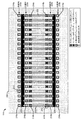
図2(図2a及び図2b)は、本開示の実施形態による、流体吐出デバイス114の上からの図を示す。図3は、図2aの上からの図にほぼ対応する流体吐出デバイス114の断面図を示す。図2a及び図3を一般に参照すると、流体吐出デバイス114は、内部に形成された第1の流体供給スロット202及び第2の流体供給スロット204を備えるシリコンダイ基板200を含む。流体スロット202及び204は、流体リザーバ120(図1)のような流体供給部(図示せず)と流体連絡する細長いスロットである。スロット間の流体循環の概念が、2つの流体スロットを有する流体吐出デバイスに関して本開示の全体にわたって説明されるが、そのような概念は2つの流体スロットを備えるデバイスに対するそれらの適用に限定されない。それどころか、例えば、6個または8個のスロットのような2つより多い流体スロットを有する流体デバイスも、スロット間の流体循環を実現するのに適したデバイスであるとして企図される。更に、他の実施形態において、流体スロットの構成は変更され得る。例えば、他の実施形態の流体スロットは、丸い穴、四角い穴、四角いトレンチなどのような様々な形状およびサイズからなることができる。
FIG. 2 (FIGS. 2a and 2b) shows a top view of the
流体吐出デバイス114は、流体チャンバ210、212を画定し、且つノズル116を有するノズル層214から基板200を分離する壁208を有するチャンバ層206を含む。チャンバ層206及びノズル層214は、例えば、ポリイミド又はSU8のような耐久性があり化学的に不活性のポリマーから形成され得る。幾つかの実施形態において、ノズル層214は、例えば、ステンレス鋼、ニッケル、パラジウム、複数の金属からなる多層構造などを含む様々なタイプの金属から形成され得る。流体チャンバ210及び212はそれぞれ、流体吐出チャンバ210及び流体ポンプチャンバ212を含む。流体チャンバ210及び212は、流体スロットと流体連絡する。流体吐出チャンバ210は、流体が流体変位アクチュエータ216(即ち、流体吐出アクチュエータ216a)の駆動により吐出されるノズル116を有する。流体ポンプチャンバ212は、流体が吐出されるノズルを備えていないという点で閉じたチャンバである。より詳細に後述されるように、ポンプチャンバ212内の流体変位アクチュエータ216(即ち、流体ポンプアクチュエータ216b)の駆動により、スロット202と204との間に流体の流れが生じる。
The
図2a及び図2bから明らかであるように、チャンバ210及び212は、スロット202及び204の内側および外側に沿ってチャンバの列を形成する。図2a及び図2bの実施形態において、第1の外側列218aは、第1の流体スロット202に隣接して、スロット202と基板200のエッジとの間に位置する。第2の外側列218bは、第2の流体スロット204に隣接して、スロット204と基板200の別のエッジとの間に位置する。チャンバの第1の内側列220aは、第1の流体スロット202に隣接して、スロット202と基板200の中央部との間に位置する。第2の内側列220bは、第2の流体スロット204に隣接して、スロット204と基板200の中央部との間に位置する。図2a及び図3の実施形態において、外側列218のチャンバは流体吐出チャンバ210であるが、内側列220のチャンバは流体ポンプチャンバ212である。しかしながら、他の実施形態において、外側列および内側列は、流体吐出チャンバ210及び流体ポンプチャンバ212の双方を含むことができる。例えば、図2bに示された実施形態は、流体吐出チャンバ210及び流体ポンプチャンバ212の双方を備える内側列220a及び220bを有する。図2bの実施形態は、チャネル222を介したスロット間の再循環を提供するが、単に内側列220a及び220bのノズル分解能(解像度)を半分に減らす。
As is apparent from FIGS. 2 a and 2 b,
流体変位アクチュエータ216は概して、ノズル116を介して液滴を吐出するために、及び/又はスロット202と204との間に流体の流れを生じさせように流体ポンプチャンバ212の中に流体変位を生成するために流体吐出チャンバ210の流体を変位させることができる素子であるように本開示の全体にわたって説明される。流体変位アクチュエータ216の一例は、熱抵抗素子である。熱抵抗素子は一般に、基板200の表面上の酸化物層、及び酸化物層、金属層およびパッシベーション層を含む薄膜スタック(個々の層は特に示されていない)から形成される。活性化される場合、熱抵抗素子からの熱がチャンバ210、212内の流体を気化させ、それにより蒸気泡の成長が流体を変位させる。圧電素子は一般に、チャンバ210、212の底部に形成された可動膜に付着された圧電材料を含む。活性化される場合、圧電材料が、膜のチャンバ210、212の中への変位を生じ、流体を変位させる圧力パルスを生成する。熱抵抗素子および圧電素子に加えて、他のタイプの流体変位アクチュエータ216も、スロット間の流体循環を生じさせるために、流体吐出デバイス114に実装するのに適しているかもしれない。例えば、流体吐出デバイス114は、静電(MEMS)アクチュエータ、機械/衝撃駆動型アクチュエータ、音声コイルアクチュエータ、磁気歪み駆動型アクチュエータなどを実装することができる。
The fluid displacement actuator 216 generally generates a fluid displacement in the
一実施形態において、図2及び図3に示されるように、流体吐出デバイス114は、流体チャネル222を含む。流体チャネル222は、第1の流体スロット202から、ダイ基板200の中央部を横切って、第2の流体スロット204まで延在する。従って、流体チャネル222は、第1の内側列220aの流体ポンプチャンバ212を第2の内側列220bのそれぞれの流体ポンプチャンバ212と結合する。流体ポンプチャンバ212は、流体チャネル222中にあり、チャネル222の一部であるとみなされ得る。従って、各流体ポンプチャンバ212は、流体チャネル222内に当該チャネルの端部の方に非対称的に(即ち、中心を外れて又は偏心して)配置される。
In one embodiment, as shown in FIGS. 2 and 3, the
図2及び図3の凡例に示されるように、内側列220a及び220bの幾つかの流体ポンプアクチュエータ216bがアクティブであり、幾つかがイナクティブである。イナクティブのポンプアクチュエータ216bは、「×」で示される。アクティブ及びイナクティブのポンプアクチュエータ216bのパターンは、流体循環モジュール126(図1)を実行するコントローラ110により制御され、第1のスロット202と第2のスロット204との間で流体を循環させる、チャネル222を介した流体の流れを生じさせる。方向の矢印は、スロット202と204との間で流体がチャネル222を介してどの方向に流れるかを示す。チャネル222を介した流体の流れの方向は、チャネル222の両端部における流体ポンプアクチュエータ216bの一方または他方を活性化することにより制御される。従って、どのポンプアクチュエータ216bがアクティブであり、どのポンプアクチュエータ216bがアクティブでないかを制御することにより、様々な流体循環のパターンがスロット202と204との間で確立され得る。図2の例に示されるように、アクティブ及びイナクティブとなるようにポンプアクチュエータ216bのグループを制御することは、第1のスロット202から第2のスロット204へ幾つかのチャネル222を介して流れる、及び第2のスロット204から第1のスロット202へ他のチャネル222を介して戻るように流れる流体を生じさせる。ポンプアクチュエータ216bがアクティブでないチャネル222は、流体の流れがほとんど又は全くない。
As shown in the legend of FIGS. 2 and 3, some
図4は、本開示の一実施形態による、流体吐出デバイス114の上からの図を示す。図4の実施形態は、追加の流体チャネルがダイ基板200の周辺部の周りで更なるスロット間の流体循環を可能にすることを除いて、図2及び図3に説明された実施形態に類似する。周辺部流体チャネル400は、基板200の両側(両方の側部)および両端部に沿って配置される。周辺部流体チャネル400は、第1の外側列218a及び第2の外側列218bから流体吐出チャンバ210及び流体ポンプチャンバ212の双方に流体的に連通するように結合される。従って、図2及び図3に関連して説明された実施形態とは異なり、外側列218及び内側列220は、流体吐出チャンバ210及び流体ポンプチャンバ212の双方を含む。流体循環のパターンは、流体ポンプチャンバ212(及びポンプアクチュエータ216b)が配置されるチャネル222に基づいて、及び流体ポンプチャンバ212が外側列218に配置される場所に基づいて、この実施形態において決定される。従って、ダイ基板200の中央部を横切ってスロットからスロットまでの流体の循環は、流体ポンプチャンバ212を備えるチャネル222を介して行われるが、流体ポンプチャンバを備えないチャネル222を介して行われない。同様に、周辺部流体チャネル400の周りでスロット202と204との間の流体の循環は、外側列218の流体ポンプチャンバ212を介して行われる。先の実施形態においてのように、どのポンプアクチュエータ216bがアクティブ及びイナクティブとなるかを制御するためにコントローラ110で実行する流体循環モジュール126が、チャネル222及び400を介したスロット間で流体がどの方向に循環するかを決定する。
FIG. 4 shows a top view of the
図5は、本開示の一実施形態による、流体吐出デバイス114の上からの図を示す。図5の実施形態は、チャンバの外側列218及びチャンバの内側列220の双方があらゆる流体ポンプチャンバ212を備えずに流体吐出チャンバ210を有することを除いて、図2及び図3に説明された実施形態に類似する。この実施形態において、流体スロット202、204の周りのチャンバ位置を占める流体ポンプチャンバ212を有する(そうでなければ、流体吐出チャンバ210に使用され得る)代わりに、流体ポンプチャンバ212及び関連するポンプアクチュエータ216bを提供する追加のチャンバ位置が、チャネル222内にダイ基板200の中央部の方に更に形成される。従って、図5に示されるように、チャネル222の何れかの端部の方の流体ポンプチャンバ212のポンプアクチュエータ216bが、チャネル222を介した流体の流れを何れかの方向に生じさせるためにコントローラ110により活性化され得る。アクティブ及びイナクティブになるようにポンプアクチュエータ216bのグループを制御することは、第1のスロット202から第2のスロット204へ幾つかのチャネル222を介して流れる、及び第2のスロット204から第1のスロット202へ他のチャネル222を介して戻るように流れる流体を生じさせる。ポンプアクチュエータ216bがアクティブでないチャネル222は、流体の流れがほとんど又は全くない。また、この実施形態において、チャネル222を介して流体スロットから/へ流れる流体は、内側列220a及び220bの流体吐出チャンバ210も流れる。
FIG. 5 shows a top view of the
図6は、本開示の別の実施形態による、流体吐出デバイス114の上からの図を示す。図6の実施形態は、図4で説明された実施形態に類似する。従って、図6の実施形態は、基板200の両側および両端部に沿って配置された周辺部流体チャネル400を含む。周辺部流体チャネル400は、第1の外側列218a及び第2の外側列218bから流体吐出チャンバ210及び流体ポンプチャンバ212に流体的に連通するように結合される。しかしながら、この実施形態において、チャンバの内側列220は、あらゆる流体ポンプチャンバ212を備えずに流体吐出チャンバ210を有する。この実施形態において、内側列220a及び220bのチャンバ位置を占める流体ポンプチャンバ212を有する(そうでなければ、流体吐出チャンバ210に使用され得る)代わりに、流体ポンプチャンバ212及び関連するポンプアクチュエータ216bを提供する追加のチャンバ位置が、チャネル222の幾つかの中にダイ基板200の中央部の方に更に形成される。流体循環のパターンは、流体ポンプチャンバ212(及びポンプアクチュエータ216b)が配置されるチャネル222に基づいて、及び流体ポンプチャンバ212が外側列218に配置される場所に基づいて、この実施形態において決定される。従って、ダイ基板200の中央部を横切ってスロットからスロットまでの流体の循環は、流体ポンプチャンバ212を備えるチャネル222を介して行われるが、流体ポンプチャンバを備えないチャネル222を介して行われない。同様に、周辺部流体チャネル400の周りでスロット202と204との間の流体の循環は、外側列218の流体ポンプチャンバ212を介して行われる。先の実施形態においてのように、どのポンプアクチュエータ216bがアクティブ及びイナクティブとなるかを制御するためにコントローラ110で実行する流体循環モジュール126が、チャネル222及び400を介したスロット間で流体がどの方向に循環するかを決定する。
FIG. 6 shows a top view of the
図7は、本開示の一実施形態による、流体吐出デバイス114の上からの図を示す。図7の実施形態は、図2で説明された実施形態に類似する。従って、外側列218のチャンバは流体吐出チャンバ210であるが、内側列220a及び220bのチャンバは流体ポンプチャンバ212である。しかしながら、この実施形態において、1つ又は複数のプレナム700がチャンバ層206に形成され、ダイ基板200の中央部の方に配置される。プレナム700は、内側列220a及び220bの双方から多数のチャネル222を一緒にする。従って、アクティブなポンプアクチュエータ216bを有する多数の流体ポンプチャンバ212によりチャネル222を介して一方のスロットから循環されている流体は、プレナム700の一方の側の中へ流れる。当該流体は、他方のスロットへ入る前に、プレナム700の他方の側から出て連続するチャネル222及びイナクティブのポンプアクチュエータ216bを有する流体ポンプチャンバ212を介して循環する。特定のチャネル及びプレナムの具現化形態または設計が図面において説明されて示されたが、チャネル及びプレナムを介したスロット間の流体循環の概念は、これら具現化形態に制限されない。それどころか、様々な他のチャネル及びプレナムの具現化形態または設計が可能であり、スロット間の流体循環を実現するのに適切であるように本明細書で企図されている。
FIG. 7 shows a top view of the
図8〜図10は、流体吐出デバイス114において流体チャネル222を介したスロット間の流体循環を行う流体ポンプアクチュエータ216bの動作モードを示す。図8は、本開示の一実施形態による、チャネルの各端部の方に配置された流体ポンプアクチュエータ216bを備える閉じた流体ポンプチャンバ212を有する流体チャネル222を示す。流体チャネル222の両端部は、流体スロット202及び204と流体連絡する。一般に、慣性ポンピングメカニズムは、2つの要因に基づいて流体チャネル222の流体ポンプアクチュエータ216bからのポンピング効果を可能にする。これらの要因は、チャネル222の長さに対する当該チャネルにおけるアクチュエータ216bの非対称的な(即ち、中心を外れた又は偏心した)配置、及びアクチュエータ216bの非対称的な動作である。
8-10 illustrate the mode of operation of the
図8に示されるように、2つの流体ポンプアクチュエータ216bのそれぞれは、チャネル222の対向する端部の方に非対称的に(即ち、中心を外れて又は偏心して)配置される。アクチュエータ216bの非対称的な動作(即ち、異なる持続時間を有する圧縮および膨張/引っ張りの流体変位の発生)と共に、この非対称的なアクチュエータの配置は、アクチュエータ216bの慣性ポンピングメカニズムを可能にする。チャネル222内でのアクチュエータ216bの非対称的位置は、チャネル222内で流体ダイオード特性(即ち、流体の一方方向への流れ)(正味の流体の流れ)を駆動する慣性メカニズムを生じさせる。アクティブなアクチュエータ216bからの流体変位は、2つの相対する方向に流体を押し動かす、チャネル222内で伝播する波動を生成する。チャネル222の長い方(即ち、アクティブなアクチュエータ216bからチャネル222の遠端部の方へ離れて)に収容されている流体の極めて大量の部分は、順方向流体アクチュエータポンプ行程(即ち、アクチュエータ216bのチャネル222への撓みが圧縮流体変位を生じる)の終端において、より大きな力学的慣性を有する。従って、このより大きな流体の固まりは、チャネル222の短い方(即ち、スロット202とアクティブなアクチュエータ216bとの間のチャネル222の短い部分)の流体に比べてゆっくり方向を逆転する。チャネル222の短い方の流体は、逆方向流体アクチュエータポンプ行程(即ち、アクティブなアクチュエータ216bの最初の静止状態またはそれ以上まで戻る当該アクチュエータ216bの撓みが、膨張流体変位を生じる)の間に力学的運動量を獲得するためのより多くの時間がある。従って、逆方向行程の終端において、チャネル222の短い方の流体は、チャネル222の長い方の流体よりも大きな力学的運動量を有する。この結果、正味の流体の流れは、図8の黒い方向矢印により示されるように、チャネル222の短い方からチャネル222の長い方への方向に移動する。正味の流体の流れは、2つの流体要素(即ち、チャネル222の短い方と長い方)の等しくない慣性特性の結果である。
As shown in FIG. 8, each of the two
異なるタイプのアクチュエータ素子は、これら動作にわたって異なるレベルの制御を提供する。例えば、図8に示されたような熱抵抗アクチュエータ素子216bは、蒸気泡800の形成および崩壊の間に流体変位を提供する。蒸気泡800の形成は圧縮流体変位を生じ、蒸気泡の崩壊は膨張または引っ張り流体変位を生じる。圧縮流体変位の持続時間(即ち、蒸気泡の形成)及び膨張流体変位の持続時間(即ち蒸気泡の崩壊)は制御可能ではない。しかしながら、変位の持続時間は非対称的(即ち、持続時間は同じ長さの時間ではない)であり、それにより熱抵抗アクチュエータは、コントローラ110により適切な間隔で活性化される場合にポンプアクチュエータ216bとして機能することが可能になる。
Different types of actuator elements provide different levels of control over these operations. For example, a thermal
図9は、本開示の一実施形態による、チャネルの各端部の方に位置する圧電流体ポンプアクチュエータ216bを備える閉じた流体ポンプチャンバ212を有する流体チャネル222を示す。また、図9は、一実施形態において、圧電アクチュエータ216bの非対称的な動作を制御するために流体循環モジュール126を実行するコントローラ110からの電圧波形を示すグラフ900も含む。圧電アクチュエータ素子は、圧電膜がチャネル222の中へと撓む場合に圧縮流体変位を提供し、圧電膜がその通常の位置へ戻る又はチャネル222の外に撓む場合に膨張/引っ張り流体変位を提供する。グラフ900が示すように、コントローラ110は、膨張/引っ張り流体変位よりも短い持続時間の圧縮流体変位を生じさせるために、流体スロット202に近い圧電ポンプアクチュエータ216bを制御している。チャネル222に非対称的に配置されたアクティブな圧電ポンプアクチュエータ216bからの変位の結果は、流体スロット202から流体スロット204へ流体を循環させる、チャネル222を介した正味の流体の流れである。図示されていないが、同じ電圧制御波形が印加されて、流体スロット204の近くの圧電ポンプアクチュエータ216bを制御する場合、チャネル222を介した流体の流れの方向は逆になり、流体スロット204から流体スロット202への流体循環を生じる。
FIG. 9 illustrates a
図10は、本開示の一実施形態による、チャネルの各端部の方に位置する圧電流体ポンプアクチュエータ216bを備える閉じた流体ポンプチャンバ212を有する流体チャネル222を示す。また、図10は、一実施形態において、圧電アクチュエータ216bの非対称的な動作を制御するために流体循環モジュール126を実行するコントローラ110からの電圧波形を示すグラフ1000も含む。図10の実施形態において、コントローラ110は、膨張/引っ張り流体変位よりも長い持続時間の圧縮流体変位を生じさせるために、流体スロット202に近い圧電ポンプアクチュエータ216bを制御している。チャネル222に非対称的に配置されたアクティブな圧電ポンプアクチュエータ216bからの変位の結果は、流体スロット204から流体スロット202へ流体を循環させる、チャネル222を介した正味の流体の流れである。図示されていないが、同じ電圧制御波形が印加されて、流体スロット204の近くの圧電ポンプアクチュエータ216bを制御する場合、チャネル222を介した流体の流れの方向は逆になり、流体スロット202から流体スロット204への流体循環を生じる。
FIG. 10 shows a
図11は、本開示の一実施形態による、流体吐出デバイス114においてスロット間で流体を循環させる例示的な方法1100の流れ図を示す。方法1100は、図1〜図10に関連して本明細書で説明された実施形態に関連付けられる。
FIG. 11 illustrates a flow diagram of an
方法1100はブロック1102から始まり、ブロック1102は、ダイ基板の中央領域上の流体を第1のスロットから第2のスロットへ第1の流体チャネルを介してポンピングし、この場合、第1の流体チャネルは、第1のスロットから第1のスロットに隣接する第1のチャンバを介して、中央領域を横切り、第2のスロットに隣接する第2のチャンバを介して第2のスロットまで延在する。方法1100のブロック1104に示されるように、流体を第1のスロットから第2のスロットまでポンピングすることは、第1のチャンバの第1のアクチュエータから異なる持続時間の圧縮および膨張の流体変位を生じさると同時に、第2のチャンバの第2のアクチュエータから流体変位を生じさせないことを含むことができる。ブロック1106に示されるように、流体を第1のスロットから第2のスロットまでポンピングすることは更に、流体を複数のアクティブなポンプアクチュエータでもって第1のスロットから複数の流体チャネルを介してプレナムの中へとポンピングし、ブロック1108に示されるように、流体をプレナムから複数の流体チャネルを介して第2のスロットへとポンピングすることを含む。
The
方法1100は、ブロック1110で継続し、ブロック1110は、中央領域上の流体を第2のスロットから第1のスロットへ第2の流体チャネルを介してポンピングし、この場合、第2の流体チャネルは、第2のスロットから第2のスロットに隣接する第3のチャンバを介して、中央領域を横切り、第1のスロットに隣接する第4のチャンバを介して第1のスロットまで延在する。方法1100のブロック1112に示されるように、流体を第2のスロットから第1のスロットまでポンピングすることは、第3のチャンバの第3のアクチュエータから異なる持続時間の圧縮および膨張の流体変位を生じさると同時に、第4のチャンバの第4のアクチュエータから流体変位を生じさせないことを含むことができる。ブロック1114に示されるように、流体を第2のスロットから第1のスロットまでポンピングすることは更に、流体を複数のアクティブなポンプアクチュエータでもって第2のスロットから複数の流体チャネルを介してプレナムへとポンピングし、ブロック1116に示されるように、流体をプレナムから複数の流体チャネルを介して第1のスロットへとポンピングすることを含む。
The
方法1100はブロック1118で継続し、この場合、ダイ基板の周辺部の周りの流体を、第1及び第2のスロットを取り囲む周辺部流体チャネルを介してポンピングする。
The
Claims (17)
基板の対向する側部に沿って且つ基板の中央領域により分離された第1及び第2の細長い流体スロットを有するダイ基板と、
前記第1及び第2のスロットとそれぞれ関連付けられ且つ前記中央領域により分離された、閉じたチャンバの第1及び第2の内側列と、
前記中央領域を横切って延在し、前記第1の内側列からの閉じたチャンバを前記第2の内側列からの閉じたチャンバと流体的に連通するように結合するための流体チャネルと、
前記チャネルを介してスロット間で流体をポンピングするための、各閉じたチャンバの中のポンプアクチュエータとを含む、流体吐出デバイス。 A fluid ejection device comprising:
A die substrate having first and second elongate fluid slots separated by a central region of the substrate along opposite sides of the substrate;
First and second inner rows of closed chambers associated with the first and second slots, respectively, and separated by the central region;
A fluid channel extending across the central region and for coupling a closed chamber from the first inner row in fluid communication with the closed chamber from the second inner row;
A fluid ejection device including a pump actuator in each closed chamber for pumping fluid between the slots through the channel.
流体を吐出するための、各ノズル付きチャンバの中の小滴吐出アクチュエータとを更に含む、請求項1に記載の流体吐出デバイス。 First and second outer rows of nozzle chambers associated with the first and second slots, respectively;
The fluid ejection device of claim 1, further comprising a droplet ejection actuator in each nozzle chamber for ejecting fluid.
前記第1のスロットに隣接し、前記基板の中央部に面する小滴吐出チャンバの第1の列と、
前記第2のスロットに隣接し、前記基板の中央部に面する小滴吐出チャンバの第2の列と、
前記基板の中央部を横切って延在し、前記第1及び第2の列の小滴吐出チャンバを介して前記第1及び第2のスロットを結合する流体チャネルと、
スロット間で前記チャネルを介して流体を循環させるためのポンプアクチュエータを有する、前記小滴吐出チャンバに隣接する前記流体チャネルのポンプチャンバとを含む、流体吐出デバイス。 First and second fluid slots along opposite sides of the substrate;
A first row of droplet ejection chambers adjacent to the first slot and facing a central portion of the substrate;
A second row of droplet ejection chambers adjacent to the second slot and facing a central portion of the substrate;
A fluid channel extending across a central portion of the substrate and coupling the first and second slots via the first and second rows of droplet ejection chambers;
A fluid ejection device comprising a pump chamber for the fluid channel adjacent to the droplet ejection chamber having a pump actuator for circulating fluid through the channel between slots.
ダイ基板の中央領域上の流体を第1のスロットから第2のスロットへ第1の流体チャネルを介してポンピングし、前記第1の流体チャネルが、前記第1のスロットから前記第1のスロットに隣接する第1のチャンバを介して、前記中央領域を横切り、前記第2のスロットに隣接する第2のチャンバを介して前記第2のスロットまで延在し、
前記中央領域上の流体を前記第2のスロットから前記第1のスロットへ第2の流体チャネルを介してポンピングし、前記第2の流体チャネルが、前記第2のスロットから前記第2のスロットに隣接する第3のチャンバを介して、前記中央領域を横切り、前記第1のスロットに隣接する第4のチャンバを介して前記第1のスロットまで延在することを含む、方法。 A method of circulating fluid between slots in a fluid ejection device, comprising:
Pumping fluid on a central region of the die substrate from a first slot to a second slot via a first fluid channel, the first fluid channel from the first slot to the first slot Extending through the first chamber adjacent to the central region and extending through the second chamber adjacent to the second slot to the second slot;
Pumping fluid on the central region from the second slot to the first slot via a second fluid channel, the second fluid channel from the second slot to the second slot Extending through the third chamber adjacent to the central region and extending through the fourth chamber adjacent to the first slot to the first slot.
それぞれが前記第1のスロットから前記第1のスロットに隣接する前記第1のチャンバのそれぞれを介して第1のプレナムまで延在する第1の組の流体サブチャネルと、
それぞれが前記第1のプレナムから前記第2のスロットに隣接する前記第2のチャンバのそれぞれを介して前記第2のスロットまで延在する第2の組の流体サブチャンネルとからなり、
流体を前記第1のスロットから前記第2のスロットまでポンピングすることが、
流体を前記第1のスロットから前記第1の組の流体サブチャネルを介して前記第1のプレナムへ、及び前記第1のプレナムから前記第2の組の流体サブチャンネルを介して前記第2のスロットへとポンピングすることを含む、請求項12に記載の方法。 The first fluid channel comprises:
A first set of fluid subchannels each extending from the first slot through each of the first chambers adjacent to the first slot to a first plenum;
A second set of fluid subchannels each extending from the first plenum through each of the second chambers adjacent to the second slot to the second slot;
Pumping fluid from the first slot to the second slot;
Fluid into said first plenum from the previous SL first slot through the first set of fluid subchannels, and the via fluid sub channel of the second set from the first plenum second 13. The method of claim 12, comprising pumping into a plurality of slots.
それぞれが前記第2のスロットから前記第2のスロットに隣接する前記第3のチャンバのそれぞれを介して第2のプレナムまで延在する第3の組の流体サブチャネルと、
それぞれが前記第2のプレナムから前記第1のスロットに隣接する前記第4のチャンバのそれぞれを介して前記第1のスロットまで延在する第4の組の流体サブチャンネルとからなり、
流体を前記第2のスロットから前記第1のスロットまでポンピングすることが、
流体を前記第2のスロットから前記第3の組の流体サブチャネルを介して前記第2のプレナムへ、及び前記第2のプレナムから前記第4の組の流体サブチャンネルを介して前記第1のスロットへとポンピングすることを含む、請求項12に記載の方法。 The second fluid channel comprises:
A third set of fluid subchannels, each extending from the second slot through each of the third chambers adjacent to the second slot to a second plenum;
A fourth set of fluid subchannels each extending from the second plenum through each of the fourth chambers adjacent to the first slot to the first slot;
Pumping fluid from the second slot to the first slot;
Fluid into the second plenum from the front Stories second slot through the third set of fluid subchannels, and the through the fourth set of fluid sub-channel from the second plenum the first 13. The method of claim 12, comprising pumping into a plurality of slots.
Applications Claiming Priority (1)
| Application Number | Priority Date | Filing Date | Title |
|---|---|---|---|
| PCT/US2011/053619 WO2013048382A1 (en) | 2011-09-28 | 2011-09-28 | Slot-to-slot circulation in a fluid ejection device |
Publications (2)
| Publication Number | Publication Date |
|---|---|
| JP2014531349A JP2014531349A (en) | 2014-11-27 |
| JP5728622B2 true JP5728622B2 (en) | 2015-06-03 |
Family
ID=47996129
Family Applications (1)
| Application Number | Title | Priority Date | Filing Date |
|---|---|---|---|
| JP2014533251A Expired - Fee Related JP5728622B2 (en) | 2011-09-28 | 2011-09-28 | Circulation between slots in fluid ejection devices |
Country Status (9)
| Country | Link |
|---|---|
| US (5) | US9211721B2 (en) |
| EP (1) | EP2760673B1 (en) |
| JP (1) | JP5728622B2 (en) |
| KR (1) | KR101908758B1 (en) |
| CN (1) | CN103826860B (en) |
| BR (1) | BR112014007224B1 (en) |
| IN (1) | IN2014CN01595A (en) |
| TW (1) | TWI485073B (en) |
| WO (1) | WO2013048382A1 (en) |
Families Citing this family (39)
| Publication number | Priority date | Publication date | Assignee | Title |
|---|---|---|---|---|
| US10259218B2 (en) * | 2014-02-25 | 2019-04-16 | Funai Electric Co., Ltd. | Ejection device for inkjet printers |
| JP6518417B2 (en) * | 2014-09-01 | 2019-05-22 | 東芝テック株式会社 | Liquid circulation system |
| CN107073962A (en) | 2014-10-30 | 2017-08-18 | 惠普发展公司,有限责任合伙企业 | Fluid ejection device |
| US10632743B2 (en) | 2014-10-31 | 2020-04-28 | Hewlett-Packard Development Company, L.P. | Fluid ejection device |
| BR112017015939A2 (en) | 2015-04-30 | 2018-07-10 | Hewlett Packard Development Co | fluid ejection device |
| JP6769088B2 (en) * | 2015-12-07 | 2020-10-14 | セイコーエプソン株式会社 | Printing equipment |
| US10457062B2 (en) * | 2016-01-08 | 2019-10-29 | Canon Kabushiki Kaisha | Liquid discharge head |
| JP6669393B2 (en) * | 2016-03-25 | 2020-03-18 | キヤノン株式会社 | Liquid discharge head, liquid discharge device, and liquid discharge head temperature control method |
| JP6708457B2 (en) * | 2016-03-29 | 2020-06-10 | キヤノン株式会社 | Liquid ejection head and liquid circulation method |
| JP6736324B2 (en) * | 2016-03-29 | 2020-08-05 | キヤノン株式会社 | Liquid ejection head |
| WO2017188993A1 (en) * | 2016-04-29 | 2017-11-02 | Hewlett-Packard Development Company, L.P. | Selectively firing a fluid circulation element |
| US11110704B2 (en) | 2016-04-29 | 2021-09-07 | Hewlett-Packard Development Company, L.P. | Selectively firing a fluid circulation element |
| EP3386756A1 (en) * | 2016-06-27 | 2018-10-17 | Hewlett-Packard Development Company, L.P. | Printhead recirculation |
| CN109641456B (en) * | 2016-11-01 | 2021-06-15 | 惠普发展公司,有限责任合伙企业 | Fluid ejection device including fluid output channel |
| US20180126342A1 (en) * | 2016-11-07 | 2018-05-10 | Chelsea Kent | Color matching device |
| CN110214087B (en) * | 2017-04-21 | 2021-02-05 | 惠普发展公司,有限责任合伙企业 | Method of fluid recirculation in a printhead, printing system, and computer readable medium |
| CN110637065B (en) | 2017-06-09 | 2022-08-09 | 惠普发展公司,有限责任合伙企业 | Ink jet printing system |
| JP7094665B2 (en) | 2017-06-13 | 2022-07-04 | キヤノン株式会社 | Recording device and recording control method |
| JP6971377B2 (en) * | 2017-07-31 | 2021-11-24 | ヒューレット−パッカード デベロップメント カンパニー エル.ピー.Hewlett‐Packard Development Company, L.P. | Fluid discharge device with built-in cross-passage |
| CN110891793B (en) | 2017-07-31 | 2021-04-09 | 惠普发展公司,有限责任合伙企业 | Fluid ejection die with enclosed lateral channels |
| WO2019059905A1 (en) | 2017-09-20 | 2019-03-28 | Hewlett-Packard Development Company, L.P. | Fluidic dies |
| JP7039231B2 (en) * | 2017-09-28 | 2022-03-22 | キヤノン株式会社 | Liquid discharge head and liquid discharge device |
| JP6945058B2 (en) * | 2017-10-19 | 2021-10-06 | ヒューレット−パッカード デベロップメント カンパニー エル.ピー.Hewlett‐Packard Development Company, L.P. | Fluid die |
| US11065883B2 (en) | 2017-11-27 | 2021-07-20 | Hewlett-Packard Development Company, L.P. | Cross-die recirculation channels and chamber recirculation channels |
| JP7066407B2 (en) | 2017-12-28 | 2022-05-13 | キヤノン株式会社 | Recording device, recording method, and program |
| JP7066406B2 (en) | 2017-12-28 | 2022-05-13 | キヤノン株式会社 | Recording device, recording method, and program |
| US11305537B2 (en) | 2018-03-12 | 2022-04-19 | Hewlett-Packard Development Company, L.P. | Nozzle arrangements and supply channels |
| JP7015926B2 (en) | 2018-03-12 | 2022-02-03 | ヒューレット-パッカード デベロップメント カンパニー エル.ピー. | Nozzle array |
| US11247470B2 (en) | 2018-03-12 | 2022-02-15 | Hewlett-Packard Development Company, L.P. | Nozzle arrangements and feed holes |
| JP7259386B2 (en) * | 2018-06-25 | 2023-04-18 | セイコーエプソン株式会社 | Liquid ejecting head and liquid ejecting device |
| JP7183023B2 (en) * | 2018-12-19 | 2022-12-05 | キヤノン株式会社 | ELEMENT SUBSTRATE, LIQUID EJECTION HEAD, AND RECORDING APPARATUS |
| JP7287042B2 (en) * | 2018-12-21 | 2023-06-06 | セイコーエプソン株式会社 | Liquid jet head and liquid jet system |
| US11104128B2 (en) | 2018-12-21 | 2021-08-31 | Seiko Epson Corporation | Liquid ejecting head and liquid ejecting system |
| JP7171424B2 (en) * | 2018-12-26 | 2022-11-15 | キヤノン株式会社 | Liquid ejection head, liquid ejection device, and liquid supply method |
| US11390081B2 (en) | 2019-02-06 | 2022-07-19 | Hewlett-Packard Development Company, L.P. | Fluid ejection device with a carrier having a slot |
| JP7341703B2 (en) * | 2019-04-02 | 2023-09-11 | キヤノン株式会社 | liquid discharge head |
| JP7419008B2 (en) | 2019-10-01 | 2024-01-22 | キヤノン株式会社 | liquid discharge head |
| WO2021194509A1 (en) * | 2020-03-27 | 2021-09-30 | Hewlett-Packard Development Company, L.P. | Fluid ejection devices with expansion member |
| WO2022086546A1 (en) * | 2020-10-23 | 2022-04-28 | Hewlett-Packard Development Company, L.P. | Asymmetrical configuration of fluid-ejection element groups, ports, and channels of printhead |
Family Cites Families (36)
| Publication number | Priority date | Publication date | Assignee | Title |
|---|---|---|---|---|
| US4480259A (en) * | 1982-07-30 | 1984-10-30 | Hewlett-Packard Company | Ink jet printer with bubble driven flexible membrane |
| US5087930A (en) * | 1989-11-01 | 1992-02-11 | Tektronix, Inc. | Drop-on-demand ink jet print head |
| JP3343875B2 (en) * | 1995-06-30 | 2002-11-11 | キヤノン株式会社 | Method of manufacturing inkjet head |
| US5818485A (en) * | 1996-11-22 | 1998-10-06 | Xerox Corporation | Thermal ink jet printing system with continuous ink circulation through a printhead |
| JP2004249741A (en) | 1998-01-22 | 2004-09-09 | Matsushita Electric Ind Co Ltd | Inkjet device |
| US6244694B1 (en) * | 1999-08-03 | 2001-06-12 | Hewlett-Packard Company | Method and apparatus for dampening vibration in the ink in computer controlled printers |
| US6132034A (en) * | 1999-08-30 | 2000-10-17 | Hewlett-Packard Company | Ink jet print head with flow control contour |
| JP2001205810A (en) * | 2000-01-28 | 2001-07-31 | Kyocera Corp | Ink-jet head |
| JP2001249741A (en) * | 2000-03-07 | 2001-09-14 | Ricoh Co Ltd | Bus system and image processor |
| US6481832B2 (en) * | 2001-01-29 | 2002-11-19 | Hewlett-Packard Company | Fluid-jet ejection device |
| US6409312B1 (en) * | 2001-03-27 | 2002-06-25 | Lexmark International, Inc. | Ink jet printer nozzle plate and process therefor |
| US6981759B2 (en) * | 2002-04-30 | 2006-01-03 | Hewlett-Packard Development Company, Lp. | Substrate and method forming substrate for fluid ejection device |
| US6880926B2 (en) * | 2002-10-31 | 2005-04-19 | Hewlett-Packard Development Company, L.P. | Circulation through compound slots |
| US6843121B1 (en) | 2003-08-25 | 2005-01-18 | Eastman Kodak Company | Measuring absolute static pressure at one or more positions along a microfluidic device |
| JP4587157B2 (en) * | 2003-10-23 | 2010-11-24 | キヤノン株式会社 | Inkjet recording head and inkjet recording apparatus |
| US7041226B2 (en) | 2003-11-04 | 2006-05-09 | Lexmark International, Inc. | Methods for improving flow through fluidic channels |
| US7271105B2 (en) * | 2004-03-17 | 2007-09-18 | Lexmark International, Inc. | Method for making a micro-fluid ejection device |
| JP4419639B2 (en) | 2004-03-26 | 2010-02-24 | ソニー株式会社 | Electrostatic MEMS actuator, micro fluid drive device including micro pump, micro fluid ejection device including ink jet printer head, and printing device including ink jet printer |
| US7254890B2 (en) * | 2004-12-30 | 2007-08-14 | Lexmark International, Inc. | Method of making a microfluid ejection head structure |
| JP4881081B2 (en) * | 2005-07-25 | 2012-02-22 | キヤノン株式会社 | Method for manufacturing liquid discharge head |
| US7850290B2 (en) * | 2006-12-28 | 2010-12-14 | Toshiba Tec Kabushiki Kaisha | Ink jet recording apparatus, ink supplying mechanism and ink supplying method |
| JP2008254199A (en) * | 2007-03-30 | 2008-10-23 | Fujifilm Corp | Ink jet recorder |
| JP4855992B2 (en) | 2007-03-30 | 2012-01-18 | 富士フイルム株式会社 | Liquid circulation device, image forming apparatus, and liquid circulation method |
| US20100072414A1 (en) * | 2008-09-23 | 2010-03-25 | The Curators Of The University Of Missouri | Microfluidic valve systems and methods |
| JP5371475B2 (en) * | 2009-02-17 | 2013-12-18 | キヤノン株式会社 | Ink jet recording head and cleaning method thereof |
| JP2010201734A (en) | 2009-03-02 | 2010-09-16 | Seiko Epson Corp | Liquid injection device and control method for liquid injection head |
| JP2010214847A (en) * | 2009-03-18 | 2010-09-30 | Fujifilm Corp | Liquid droplet ejection head and image forming apparatus |
| JP2010221443A (en) | 2009-03-19 | 2010-10-07 | Fujifilm Corp | Droplet delivering apparatus |
| US8113628B2 (en) * | 2009-06-19 | 2012-02-14 | Eastman Kodak Company | Inkjet printers having micro-fluidic actuators |
| US8113627B2 (en) | 2009-06-19 | 2012-02-14 | Eastman Kodak Company | Micro-fluidic actuator for inkjet printers |
| US8235505B2 (en) * | 2009-06-30 | 2012-08-07 | Eastman Kodak Company | Flow through drop dispenser including porous member |
| US8182073B2 (en) * | 2009-06-30 | 2012-05-22 | Eastman Kodak Company | Flow through dispenser including diverter cooling channel |
| JP5364084B2 (en) * | 2010-03-16 | 2013-12-11 | パナソニック株式会社 | Inkjet device |
| BR112013000372B1 (en) * | 2010-07-28 | 2020-11-03 | Hewlett-Packard Development Company, L. P | fluid ejection assemblies |
| US8517518B2 (en) * | 2010-11-09 | 2013-08-27 | Canon Kabushiki Kaisha | Recording apparatus and liquid ejection head |
| US9902157B2 (en) * | 2016-01-08 | 2018-02-27 | Canon Kabushiki Kaisha | Liquid ejection substrate, liquid ejection head, and liquid ejection apparatus |
-
2011
- 2011-09-28 EP EP11873409.4A patent/EP2760673B1/en active Active
- 2011-09-28 CN CN201180073806.8A patent/CN103826860B/en active Active
- 2011-09-28 WO PCT/US2011/053619 patent/WO2013048382A1/en active Application Filing
- 2011-09-28 BR BR112014007224-8A patent/BR112014007224B1/en active IP Right Grant
- 2011-09-28 IN IN1595CHN2014 patent/IN2014CN01595A/en unknown
- 2011-09-28 KR KR1020147007985A patent/KR101908758B1/en active IP Right Grant
- 2011-09-28 US US14/241,330 patent/US9211721B2/en not_active Expired - Fee Related
- 2011-09-28 JP JP2014533251A patent/JP5728622B2/en not_active Expired - Fee Related
-
2012
- 2012-09-19 TW TW101134270A patent/TWI485073B/en not_active IP Right Cessation
-
2015
- 2015-12-03 US US14/958,022 patent/US9457584B2/en active Active
-
2016
- 2016-08-31 US US15/252,433 patent/US9623659B2/en active Active
-
2017
- 2017-02-15 US US15/433,827 patent/US9969177B2/en active Active
-
2018
- 2018-03-14 US US15/921,614 patent/US10336090B2/en active Active
Also Published As
| Publication number | Publication date |
|---|---|
| US9211721B2 (en) | 2015-12-15 |
| TW201328893A (en) | 2013-07-16 |
| US10336090B2 (en) | 2019-07-02 |
| WO2013048382A1 (en) | 2013-04-04 |
| US20160082745A1 (en) | 2016-03-24 |
| CN103826860B (en) | 2015-12-02 |
| US9457584B2 (en) | 2016-10-04 |
| US20140362143A1 (en) | 2014-12-11 |
| CN103826860A (en) | 2014-05-28 |
| KR101908758B1 (en) | 2018-10-16 |
| BR112014007224B1 (en) | 2020-06-16 |
| BR112014007224A2 (en) | 2017-04-04 |
| EP2760673A4 (en) | 2015-12-02 |
| EP2760673A1 (en) | 2014-08-06 |
| JP2014531349A (en) | 2014-11-27 |
| US9969177B2 (en) | 2018-05-15 |
| US20170157945A1 (en) | 2017-06-08 |
| KR20140085436A (en) | 2014-07-07 |
| US20160368266A1 (en) | 2016-12-22 |
| IN2014CN01595A (en) | 2015-05-08 |
| US9623659B2 (en) | 2017-04-18 |
| US20180201024A1 (en) | 2018-07-19 |
| EP2760673B1 (en) | 2019-04-03 |
| TWI485073B (en) | 2015-05-21 |
Similar Documents
| Publication | Publication Date | Title |
|---|---|---|
| JP5728622B2 (en) | Circulation between slots in fluid ejection devices | |
| JP5731712B2 (en) | Fluid ejection device with fluid displacement actuator and associated method | |
| EP2571696B1 (en) | Fluid ejection device with circulation pump | |
| US8721061B2 (en) | Fluid ejection device with circulation pump | |
| JP5777706B2 (en) | Fluid ejecting apparatus having circulation pump | |
| US20190168512A1 (en) | Fluid ejection device | |
| US20180215148A1 (en) | Fluid ejection device | |
| WO2018022103A1 (en) | Fluid ejection device | |
| US20190134987A1 (en) | Fluid ejection device |
Legal Events
| Date | Code | Title | Description |
|---|---|---|---|
| A131 | Notification of reasons for refusal |
Free format text: JAPANESE INTERMEDIATE CODE: A131 Effective date: 20150106 |
|
| A521 | Request for written amendment filed |
Free format text: JAPANESE INTERMEDIATE CODE: A523 Effective date: 20150212 |
|
| TRDD | Decision of grant or rejection written | ||
| A01 | Written decision to grant a patent or to grant a registration (utility model) |
Free format text: JAPANESE INTERMEDIATE CODE: A01 Effective date: 20150331 |
|
| A61 | First payment of annual fees (during grant procedure) |
Free format text: JAPANESE INTERMEDIATE CODE: A61 Effective date: 20150406 |
|
| R150 | Certificate of patent or registration of utility model |
Ref document number: 5728622 Country of ref document: JP Free format text: JAPANESE INTERMEDIATE CODE: R150 |
|
| R250 | Receipt of annual fees |
Free format text: JAPANESE INTERMEDIATE CODE: R250 |
|
| R250 | Receipt of annual fees |
Free format text: JAPANESE INTERMEDIATE CODE: R250 |
|
| R250 | Receipt of annual fees |
Free format text: JAPANESE INTERMEDIATE CODE: R250 |
|
| R250 | Receipt of annual fees |
Free format text: JAPANESE INTERMEDIATE CODE: R250 |
|
| R250 | Receipt of annual fees |
Free format text: JAPANESE INTERMEDIATE CODE: R250 |
|
| LAPS | Cancellation because of no payment of annual fees |