CN110891663B - Toy (A) - Google Patents

Toy (A) Download PDF

Info

Publication number
CN110891663B
CN110891663B CN201780077391.9A CN201780077391A CN110891663B CN 110891663 B CN110891663 B CN 110891663B CN 201780077391 A CN201780077391 A CN 201780077391A CN 110891663 B CN110891663 B CN 110891663B
Authority
CN
China
Prior art keywords
wheels
support body
toy
support
connection surface
Prior art date
Legal status (The legal status is an assumption and is not a legal conclusion. Google has not performed a legal analysis and makes no representation as to the accuracy of the status listed.)
Expired - Fee Related
Application number
CN201780077391.9A
Other languages
Chinese (zh)
Other versions
CN110891663A (en
Inventor
G·阿比亚
Current Assignee (The listed assignees may be inaccurate. Google has not performed a legal analysis and makes no representation or warranty as to the accuracy of the list.)
Ferrero Trade Luxembourg Ltd
Original Assignee
Ferrero Trade Luxembourg Ltd
Priority date (The priority date is an assumption and is not a legal conclusion. Google has not performed a legal analysis and makes no representation as to the accuracy of the date listed.)
Filing date
Publication date
Application filed by Ferrero Trade Luxembourg Ltd filed Critical Ferrero Trade Luxembourg Ltd
Publication of CN110891663A publication Critical patent/CN110891663A/en
Application granted granted Critical
Publication of CN110891663B publication Critical patent/CN110891663B/en
Expired - Fee Related legal-status Critical Current
Anticipated expiration legal-status Critical

Links

Images

Classifications

    • AHUMAN NECESSITIES
    • A63SPORTS; GAMES; AMUSEMENTS
    • A63HTOYS, e.g. TOPS, DOLLS, HOOPS OR BUILDING BLOCKS
    • A63H17/00Toy vehicles, e.g. with self-drive; ; Cranes, winches or the like; Accessories therefor
    • AHUMAN NECESSITIES
    • A63SPORTS; GAMES; AMUSEMENTS
    • A63HTOYS, e.g. TOPS, DOLLS, HOOPS OR BUILDING BLOCKS
    • A63H17/00Toy vehicles, e.g. with self-drive; ; Cranes, winches or the like; Accessories therefor
    • A63H17/26Details; Accessories
    • A63H17/262Chassis; Wheel mountings; Wheels; Axles; Suspensions; Fitting body portions to chassis
    • BPERFORMING OPERATIONS; TRANSPORTING
    • B29WORKING OF PLASTICS; WORKING OF SUBSTANCES IN A PLASTIC STATE IN GENERAL
    • B29CSHAPING OR JOINING OF PLASTICS; SHAPING OF MATERIAL IN A PLASTIC STATE, NOT OTHERWISE PROVIDED FOR; AFTER-TREATMENT OF THE SHAPED PRODUCTS, e.g. REPAIRING
    • B29C45/00Injection moulding, i.e. forcing the required volume of moulding material through a nozzle into a closed mould; Apparatus therefor
    • B29C45/0001Injection moulding, i.e. forcing the required volume of moulding material through a nozzle into a closed mould; Apparatus therefor characterised by the choice of material
    • BPERFORMING OPERATIONS; TRANSPORTING
    • B29WORKING OF PLASTICS; WORKING OF SUBSTANCES IN A PLASTIC STATE IN GENERAL
    • B29CSHAPING OR JOINING OF PLASTICS; SHAPING OF MATERIAL IN A PLASTIC STATE, NOT OTHERWISE PROVIDED FOR; AFTER-TREATMENT OF THE SHAPED PRODUCTS, e.g. REPAIRING
    • B29C45/00Injection moulding, i.e. forcing the required volume of moulding material through a nozzle into a closed mould; Apparatus therefor
    • B29C45/03Injection moulding apparatus
    • B29C45/13Injection moulding apparatus using two or more injection units co-operating with a single mould
    • BPERFORMING OPERATIONS; TRANSPORTING
    • B29WORKING OF PLASTICS; WORKING OF SUBSTANCES IN A PLASTIC STATE IN GENERAL
    • B29CSHAPING OR JOINING OF PLASTICS; SHAPING OF MATERIAL IN A PLASTIC STATE, NOT OTHERWISE PROVIDED FOR; AFTER-TREATMENT OF THE SHAPED PRODUCTS, e.g. REPAIRING
    • B29C45/00Injection moulding, i.e. forcing the required volume of moulding material through a nozzle into a closed mould; Apparatus therefor
    • B29C45/16Making multilayered or multicoloured articles
    • BPERFORMING OPERATIONS; TRANSPORTING
    • B29WORKING OF PLASTICS; WORKING OF SUBSTANCES IN A PLASTIC STATE IN GENERAL
    • B29KINDEXING SCHEME ASSOCIATED WITH SUBCLASSES B29B, B29C OR B29D, RELATING TO MOULDING MATERIALS OR TO MATERIALS FOR MOULDS, REINFORCEMENTS, FILLERS OR PREFORMED PARTS, e.g. INSERTS
    • B29K2023/00Use of polyalkenes or derivatives thereof as moulding material
    • B29K2023/04Polymers of ethylene
    • B29K2023/06PE, i.e. polyethylene
    • BPERFORMING OPERATIONS; TRANSPORTING
    • B29WORKING OF PLASTICS; WORKING OF SUBSTANCES IN A PLASTIC STATE IN GENERAL
    • B29LINDEXING SCHEME ASSOCIATED WITH SUBCLASS B29C, RELATING TO PARTICULAR ARTICLES
    • B29L2031/00Other particular articles
    • B29L2031/52Sports equipment ; Games; Articles for amusement; Toys
    • B29L2031/5209Toys

Landscapes

  • Engineering & Computer Science (AREA)
  • Manufacturing & Machinery (AREA)
  • Mechanical Engineering (AREA)
  • Toys (AREA)

Abstract

本申请公开了一种用于制造玩具的方法,所述玩具特别是玩具车。根据优选实施例,所述方法提出进行注塑模制的过程,该过程具有形成玩具车的基体(40)的第一步骤以及形成轮(60)的第二步骤,该第二步骤直接在先前形成的基体上进行。所获得的玩具车的特征在于,其具有在轮和基体之间不能分开的连接部。

Figure 201780077391

The present application discloses a method for manufacturing a toy, particularly a toy vehicle. According to a preferred embodiment, the method proposes a process of injection moulding with a first step of forming the base ( 40 ) of the toy car and a second step of forming the wheel ( 60 ), which is formed directly on the previous performed on the substrate. The toy vehicle obtained is characterized in that it has an inseparable connection between the wheel and the base body.

Figure 201780077391

Description

Toy (A)
Technical Field
The present invention relates to the field of toys, in particular to toys obtained by injection moulding and made of plastic material. In this application, the present invention is directed to a toy, such as a toy vehicle, provided with wheels for its movement.
In the above field, the present invention proposes a new toy manufacturing method and a new toy innovation.
Background
A typical example of a toy vehicle or vehicle is described in document EP 0074765. The toy vehicle or vehicle is constructed from a limited number of components: a base, a body and a series of wheels mounted on the base. The base is made of a single piece of plastic material and includes four axles on which the wheels of the toy vehicle are mounted. The axle in question has a widened end with which the wheel is mounted.
It should now be noted that in the technical field in question there is a constant need to find new solutions that can achieve one or more of the following objectives:
-simplifying construction schemes and manufacturing processes; and
finding new original solutions that can arouse the interest of children.
Disclosure of Invention
It is therefore an object of the present invention to improve the above-mentioned known solutions so that one or more of the above-mentioned objects can be achieved.
In particular, the invention relates to a method according to claim 1 and a toy according to claim 7 and claim 12.
The claims form an integral part of the technical teaching provided by the invention in relation to the invention.
Drawings
Other characteristics and advantages of the invention will emerge clearly from the ensuing description with reference to the accompanying drawings, which are provided purely as non-limiting examples, in which:
figure 1 shows an example of a toy obtained by the method according to the invention;
figure 2 shows a bottom part of the toy of figure 1;
FIGS. 3A and 3B are schematic illustrations of the process of the invention;
figures 4A and 4B are schematic views of the toy of figure 1, with the toy wheel again in two respective different positions;
figures 5A and 5B show the same concept as that schematically represented in figures 4A and 4B, but represented by another example of a toy;
figures 6A and 6B are schematic illustrations of a method according to the invention for providing the toy of figures 5A and 5B;
figures 7A, 7B and 7C show a method for manufacturing a toy according to the prior art;
figure 8 shows a toy obtained with the method shown in figures 7A, 7B and 7C; and
figure 9 shows another example of a toy obtained by the method according to the invention.
Detailed Description
In the following description, numerous specific details are set forth in order to provide a thorough understanding of the embodiments. Embodiments may be provided without one or more of the specific details, or with other methods, components, materials, etc. In other instances, well-known structures, materials, or operations are not shown or described in detail to avoid obscuring aspects of the embodiments.
Reference signs used herein are provided merely for convenience and thus do not limit the scope of protection or the scope of the embodiments.
As mentioned above, the present invention generally relates to toys provided with wheels and made of plastic material.
The use of plastics materials for the manufacture of toys is widespread today, due to a series of advantages that these materials guarantee, among others, i) that objects can be manufactured in a wide range of configurations, and ii) that the processing and handling of the materials is relatively simple and inexpensive.
Figure 8 illustrates one known toy vehicle technical solution. This toy car includes: a support body 3, a vehicle body 1 and wheels 2 rotatably mounted on the support body 3. As in the known solution discussed in the above reference EP 0074765, the supporting body 3 itself comprises an axle 31 having a widened end on which the wheel 2 is inserted.
The support body 3 and the wheel 2 are made of plastic material and, in particular, are both obtained by an injection moulding process.
In this regard, fig. 7A-C schematically illustrate a method for manufacturing and assembling the two components. The method has two different injection moulding processes, the first one for forming the support body 3 using a first mould 101 (fig. 7A) and the second one for forming the wheel 2 using a second mould 103 (fig. 7B). The parts are removed once formed in the respective molds and joined together in a subsequent step (fig. 7C). The latter operation is typically performed manually.
The present invention proposes a new manufacturing method that improves the above-mentioned technical solution.
In the following, the method described in the present application will be described with reference to a process for manufacturing toy vehicles, but it is obvious that the same principles can generally be used to provide different types of toys.
Referring now to fig. 1, fig. 1 shows a toy vehicle comprised of a support body 40, a body 30, and wheels 60 rotatably mounted on the support body 40.
The support body 40 and the wheel 60 are manufactured according to the method described herein.
In general, the method envisages implementing an injection moulding process having: a first step of forming one of the two parts, i.e. the support or the wheel; and a second step of forming another component, namely a wheel or support, which is formed directly on the previously manufactured component.
In particular, the method uses a molding assembly predisposed to have two different configurations: a first configuration in which one or more cavities are defined to enable injection moulding of a first component, such as a support body; and a second configuration in which one or more cavities are defined to enable injection moulding of a second component, namely a wheel set, again with reference to the above example.
For ease of illustration, referring again to the example described above, in the second configuration of the molding assembly, the support body formed in the previous step continues to remain within the molding assembly and itself defines, with a certain portion thereof, the cavity of the molding assembly for molding the wheel.
Thus, the wheel is directly moulded on the support and, at the end of the process, the wheel is mounted on the support so that it can rotate freely.
As will be seen from the following, the aforementioned portion of the support body that is to delimit and define the cavity for forming the wheel in the moulding assembly may have a preferably conical or frustoconical shape, the advantages of which will be discussed below.
Preferred embodiments of the method described herein will now be described.
Referring to the embodiment shown in fig. 3A and 3B, which uses a molding assembly 20, the molding assembly 20 comprises a fixed block 22 and two differently configured moving blocks 23, 24, 25 and 23', 24', 25' predisposed for optional connection with the block 22 and operating with the block 22. By means of these mobile blocks, the moulding assembly is predisposed to have a first configuration defined by the block 22 and the blocks 23, 24, 25 and a second configuration defined by the block 22 and the blocks 23', 24', 25 '.
Referring to the first configuration shown in fig. 3A, the molding assembly of the present application defines a cavity 300 for molding the support body 40 of the toy. One or more runners (not shown) made in the fixed block 22 feed molten plastic material forming the component into the cavity 300. Fig. 3A shows the support body 40 already formed in the cavity 300.
In a second configuration, shown in fig. 3B, the molding assembly 20 continues to encapsulate the formed support, thereby defining therewith a set of cavities 400 for the molding wheel 60. As can be seen from this figure, the cavity in question is delimited both by the moulding surfaces of the blocks and directly by the various portions of the support itself. The wheel 60 is formed in the cavity 400 directly on these portions of the support body.
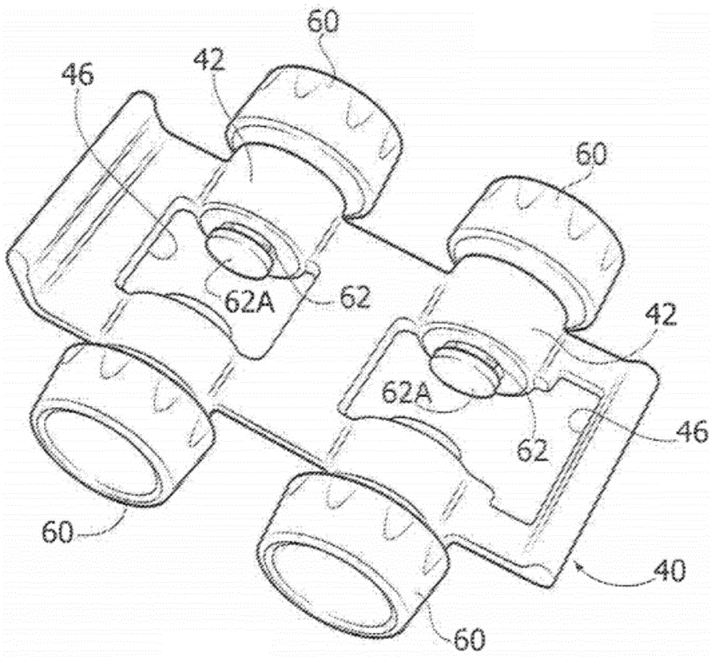
For a clearer understanding of the foregoing, reference is now made to fig. 2 and 4A, which show in detail the components of a toy vehicle obtained by the method described in the present application.
With reference to fig. 2, the supporting body 40 has four annular portions 42, the annular portions 42 being provided with internal holes 42' (fig. 4B) in which respective pins 62 are received, the pins 62 being made in a single piece with the respective wheel 60. The pin 62 has a widened end 62A and projects from the annular portion 42 and within the opening 46 formed in the support 40. The internal holes 42' are smaller than the widened end of the pins 62, at least in their portion facing the widened end 62A, so that the wheels are constrained and cannot move out of the portion 42.
It may now be noted that the internal bore 42' corresponds to the above-mentioned portion of the support body designed to delimit the cavity 400 for the moulding wheel 60. In particular, as can be clearly seen in fig. 3B, these holes are predisposed for delimiting the cavity 400 and the corresponding shaped surfaces of the blocks 22, 23', 24' and 25' which determine the second configuration of the molding assembly. The above-mentioned runners made in the fixed block 22 are designed to feed the molten plastic material also into the cavity 400 itself. Fig. 3B shows the wheels 60 and their pins 62, which have been formed in the respective cavities 400.
Referring to fig. 4A, it may again be noted that the internal bore 42' has a conical or frustoconical shape for at least a portion of their extension. The pins 62 are obtained directly in these holes and therefore have a perfectly complementary conical shape. These conical portions of the bore 42 'and pin 62 are indicated by reference numerals 42' C and 62C, respectively. Furthermore, the pins 62 are formed so as to cross the hole 42' and project from the portion 42, so as to position their ends 62A at a given distance from the portion 42.
In various preferred embodiments, the plastic material used is different for the support and the wheel. In particular, it is preferred to use two materials with low chemical-physical affinity to prevent any adhesion between the two materials. Obviously, it is preferred that the melting point of the material used to form the support body is higher than the melting point of the wheel material, so as to prevent the support body from locally melting in its portion 42'C when this portion 42' C delimits the cavity 400 for forming the wheel during the second step of the moulding process. In various preferred embodiments, the support body is made of nylon and the wheel is made of polyethylene.
At the end of the second molding step, the molded assembly is opened and the already assembled whole consisting of the support body 40 and the wheel 60 can be taken out.
It should now be noted that the wheel 60 is completely free to rotate even if the wheel has been directly moulded on the support.
This is ensured by the above-mentioned conical portions 42'C and 62C, which conical portions 42' C and 62C constitute the interface of the rotatable connection between the wheel 60 and the support body 40.
In fact, with reference to fig. 4A and 4B, it can be noted that once the support body 40 and the wheel 60 are removed from the molding assembly, the wheel 60 does not remain in the condition shown in fig. 3B and 4A, but tends to move towards the outside by gravity until their widened end 62A bears on the annular portion 42. The conical portions 42' C and 62C just facilitate this movement.
In this new position, a gap 80 is created between the pin 62 of the wheel and the hole 42' of the portion 42, which gap 80 puts the wheel in a freely rotatable condition with respect to the support body. The axis of rotation of the wheel corresponds generally to the geometric axis of the conical portions 42' C and 62C.
It should now be noted that different variants of the above described embodiments can be envisaged.
First, the moulding steps described can be reversed, so that the wheels are moulded first and then the support body, again in a condition in which the second step is carried out directly on the part already formed in the first step. For this purpose, it is sufficient to envisage different configurations of the blocks of the molding assembly, in particular of the forming surfaces thereof.
Furthermore, the specific structure of the toy and its components obtained by the method described herein may also differ from that set forth above.
In this respect, fig. 5A-5B show an alternative toy solution, in which the so-called male-female configuration of the connection between the wheel and the support body is completely reversed with respect to that shown in fig. 2.
The support body of the solution shown in the previous figures has in fact an axle 162-instead of the annular portion 42 as in the previously shown solution-and the wheel 60' has a central hub 142 connected to the aforementioned axle (instead of the pin 62).
In addition to the above differences, in this scheme the general principles shown are reproduced in a manner that corresponds exactly to the content described above.
In the present application, fig. 6A and 6B show a method and a device for manufacturing a support body and a wheel in this variant embodiment.
In a manner entirely corresponding to that described above, the moulding assembly 20' used is also constituted in this case by distinct blocks and is predisposed by them to have two configurations, a first configuration-as shown in fig. 6A-in which cavities 300' for moulding the support body are defined, and a second configuration-as shown in fig. 6B-in which a set of cavities 400' for moulding the wheel are defined.
The cavity 400' is delimited by the outer surface of the shafts 162 previously formed by the support, on which the moulding of the wheel is carried out directly. In particular, the hubs 142 of the wheels 60' are formed on these shafts.
Similar to the bore 42' and pin 62 of the version shown in fig. 2, the shaft 162 has a conical shape for at least a portion of its extension, and thus the hub 142 will have an internal bore of a fully complementary shape. In addition, the shaft 162 has a widened end portion 162A, just like the pin 62 of the FIG. 2 version. The conical surfaces of the shaft and hub are indicated in the figures by reference numerals 162C and 142' C, respectively.
Furthermore, in a manner similar to that described above with reference to fig. 4A and 4B, after the support body and the wheel 60 'are extracted from the molding assembly 20', the wheel moves towards the outside of the shaft 162 due to gravity until it comes into contact with their respective widened end portions 162A, thus creating a gap 80 'which puts the wheel 60' in a condition of free rotation with respect to the shaft (fig. 5A and 5B).
In view of the foregoing, the advantages of the approaches described herein will now be apparent.
Firstly, the process described in the present application clearly has the following advantages compared with the known solutions mentioned at the outset: the support body and the wheel can be manufactured in a single moulding process, eliminating the assembly step between the support body and the wheel, which is necessary in known processes.
Then, focusing on the toy obtained by the method described in the present application, it is possible to note that it is characterized by a connection between the wheel and the support that cannot be separated in practice, thanks to the widened ends 62A and 162A (provided for constraining the wheel to the support).
In this respect, in various preferred embodiments, such as the one shown, the above-mentioned widened end has a circular section with a diameter at least 20% greater than the diameter of the smaller section of the hole in which the respective pin or shaft is received.
Thanks to the above features, the risk that a child may detach the wheel from the support body is completely eliminated, thus ensuring that the child does not suffer any risk in connection with handling small parts.
Finally, it should be noted that, thanks to the method described in the present application, the manufacture of toys with movable wheels is greatly simplified, thus enabling a wide range of original solutions to be produced within the industry at controlled costs when producing the toys. In this regard, figure 9 shows an example of a toy which is characterized by a long series of wheels mounted on a single body. In view of the above, the toy may be directly formed and obtained by the injection molding process provided in the method described herein.
Of course, without prejudice to the principle of the invention, the details of construction and the embodiments may vary, even significantly, with respect to what has been illustrated herein purely by way of non-limiting example, without thereby departing from the scope of the invention, as defined by the annexed claims.

Claims (13)

1.一种用于制造玩具的方法,其中所述玩具包括:1. A method for making a toy, wherein the toy comprises: -支撑体;- support body; -多个轮(60;60'),所述多个轮围绕相应的旋转轴线可旋转地安装在所述支撑体上;- a plurality of wheels (60; 60') mounted on the support body rotatably about respective axes of rotation; 所述方法的特征在于,所述方法包括以下步骤:The method is characterized in that the method comprises the following steps: -提供模制组件(20;20'),用于执行注塑模制过程;- providing a moulding assembly (20; 20') for carrying out the injection moulding process; -将所述模制组件(20;20')设置在第一构造中,在第一构造中,限定一个或多个第一模制空腔(300;300'),用于形成所述支撑体或所述多个轮(60;60');- arranging the moulding assembly (20; 20') in a first configuration defining one or more first moulding cavities (300; 300') for forming the support body or said plurality of wheels (60; 60'); -通过第一塑料材料在所述一个或多个第一模制空腔(300;300')内注塑模制所述支撑体或所述多个轮(60;60');- injection moulding the support body or the plurality of wheels (60; 60') by means of a first plastic material within the one or more first moulding cavities (300; 300'); -将所述模制组件(20;20')设置在第二构造中,在所述第二构造中,限定一个或多个第二模制空腔(400;400'),用于在所述支撑体上制造所述多个轮(60;60')或在所述多个轮(60;60')上制造所述支撑体;- arranging the moulding assembly (20; 20') in a second configuration in which one or more second moulding cavities (400; 400') are defined for use in the manufacturing said plurality of wheels (60; 60') on said support body or manufacturing said support body on said plurality of wheels (60; 60'); -通过第二塑料材料在所述一个或多个第二模制空腔(400;400')内在所述支撑体上注塑模制所述多个轮(60;60')或在所述多个轮(60;60')上注塑模制所述支撑体;- injection moulding of said plurality of wheels (60; 60') on said support by means of a second plastic material within said one or more second moulding cavities (400; 400') or in said plurality of The support body is injection-molded on each wheel (60; 60'); 其中,所述一个或多个第一模制空腔(300;300')被设置成用于在所述支撑体中或在所述多个轮(60;60')中提供第一连接表面(42'C;142'C),所述第一连接表面用于围绕所述旋转轴线连接到所述多个轮(60;60')或所述支撑体,其中wherein the one or more first moulding cavities (300; 300') are arranged for providing a first connection surface in the support body or in the plurality of wheels (60; 60') (42'C; 142'C), said first connection surface for connection to said plurality of wheels (60; 60') or said support around said axis of rotation, wherein 所述一个或多个第二模制空腔(400;400')由所述第一连接表面(42'C;142'C)界定,并且其中the one or more second moulding cavities (400; 400') are bounded by the first connection surface (42'C; 142'C), and wherein 注塑模制所述轮(60;60')或所述支撑体确定了抵靠所述第一连接表面(42'C;142'C)产生第二连接表面(62C;162C),用于使所述多个轮与所述支撑体连接或用于使所述支撑体与所述多个轮连接;Injection moulding of the wheel (60; 60') or the support defines the creation of a second connection surface (62C; 162C) against the first connection surface (42'C; 142'C) for making the plurality of wheels are connected to the support body or are used to connect the support body to the plurality of wheels; 其中,所述第二连接表面(62C;162C)和第一连接表面(42'C;142'C)具有围绕所述旋转轴线延伸的圆锥形形状或截头圆锥形形状。Therein, the second connection surface (62C; 162C) and the first connection surface (42'C; 142'C) have a conical or frusto-conical shape extending around the axis of rotation. 2.根据权利要求1所述的方法,其中,所述方法包括在所述支撑体中形成环形部分(42),所述环形部分具有设计成构成所述第一连接表面(42'C)的内表面,并且2. The method according to claim 1, wherein the method comprises forming an annular portion (42) in the support, the annular portion having a surface designed to constitute the first connection surface (42'C) inner surface, and 所述方法还包括在所述多个轮(60)中形成销(62),其限定了设计成构成所述第二连接表面(62C)的外表面。The method also includes forming pins (62) in the plurality of wheels (60) that define an outer surface designed to form the second connection surface (62C). 3.根据权利要求2所述的方法,其中,所述销(62)和所述环形部分(42)按照这样的构造形成,在所述构造中,所述销横过所述环形部分(42),并通过加宽端部(62A)突伸,所述加宽端部位于距所述环形部分(42)给定距离处。3. The method of claim 2, wherein the pin (62) and the annular portion (42) are formed in a configuration in which the pin traverses the annular portion (42) ) and protrudes through a widened end (62A) located at a given distance from said annular portion (42). 4.根据权利要求1所述的方法,其中,所述方法包括在所述多个轮(60')中形成毂(142),所述毂具有设计成构成所述第一连接表面(142'C)的内表面,并且4. The method of claim 1, wherein the method comprises forming a hub (142) in the plurality of wheels (60'), the hub having a surface designed to form the first connection surface (142') C) the inner surface, and 所述方法还包括在所述支撑体中形成轴(162),其限定了设计成构成所述第二连接表面(162C)的外表面。The method also includes forming a shaft (162) in the support that defines an outer surface designed to constitute the second connection surface (162C). 5.根据权利要求4所述的方法,其中,所述轴(162)和所述毂(142)按照这样的构造形成,在所述构造中,所述轴横过所述毂(142),并通过加宽端部(162A)突伸,所述加宽端部位于距所述毂(142)给定距离处。5. The method of claim 4, wherein the shaft (162) and the hub (142) are formed in a configuration in which the shaft traverses the hub (142), And protrudes through a widened end (162A) located at a given distance from the hub (142). 6.根据权利要求1-5中任一项所述的方法,其中,所述第二塑料材料 不同于所述第一塑料材料,并且所述第一塑料材料的特征是熔点高于所述第二塑料材料的熔点。6. The method of any of claims 1-5, wherein the second plastic material is different from the first plastic material and the first plastic material is characterized by a higher melting point than the first plastic material 2. The melting point of the plastic material. 7.根据权利要求1-5中任一项所述的方法,其中,所述玩具是玩具车。7. The method of any of claims 1-5, wherein the toy is a toy vehicle. 8.一种通过注塑模制方法获得的玩具,其中,所述玩具包括:8. A toy obtained by an injection molding method, wherein the toy comprises: -支撑体;和- a support body; and -多个轮(60;60'),所述多个轮围绕相应的旋转轴线可旋转地安装在所述支撑体上;- a plurality of wheels (60; 60') mounted on the support body rotatably about respective axes of rotation; 其特征在于,所述支撑体通过注塑模制第一塑料材料获得,所述多个轮(60;60')通过注塑模制第二塑料材料获得;characterized in that the support body is obtained by injection molding a first plastic material, and the plurality of wheels (60; 60') are obtained by injection molding a second plastic material; 其中,模制所述多个轮(60;60')或所述支撑体的步骤在已经形成的所述支撑体或所述多个轮上进行;wherein the step of moulding the plurality of wheels (60; 60') or the support body is carried out on the support body or the plurality of wheels already formed; 并且其中所述支撑体或所述多个轮(60;60')具有第一连接表面(42'C;142'C),用于围绕所述旋转轴线可旋转地连接到所述多个轮或所述支撑体,所述多个轮或所述支撑体具有第二连接表面(62C;162C),所述第二连接表面通过在所述第一连接表面上注塑模制而获得并与所述第一连接表面接合,用于可旋转地连接到所述支撑体或所述多个轮(60;60'),and wherein said support or said plurality of wheels (60; 60') has a first connecting surface (42'C; 142'C) for rotatably connecting to said plurality of wheels about said axis of rotation or the support body, the plurality of wheels or the support body having a second connecting surface (62C; 162C) obtained by injection moulding on the first connecting surface and connected to the said first connection surface engages for rotatable connection to said support or said plurality of wheels (60; 60'), 其中,所述第二连接表面(62C;162C)和第一连接表面(42'C;142'C)具有围绕所述旋转轴线延伸的圆锥形形状或截头圆锥形形状。Therein, the second connection surface (62C; 162C) and the first connection surface (42'C; 142'C) have a conical or frusto-conical shape extending around the axis of rotation. 9.根据权利要求8所述的玩具,其中,所述玩具在所述支撑体中具有环形部分(42),所述环形部分具有设计成构成所述第一连接表面(42'C)的内表面,并且9. A toy according to claim 8, wherein the toy has an annular portion (42) in the support body, the annular portion having an inner portion designed to form the first connection surface (42'C) surface, and 所述玩具在所述多个轮(60)中具有销(62),所述销限定了设计成构成所述第二连接表面(62C)的外表面。The toy has pins (62) in the plurality of wheels (60), the pins defining an outer surface designed to form the second connection surface (62C). 10.根据权利要求9所述的玩具,其中,所述销横过所述环形部分(42),并通过加宽端部(62A)突伸,所述加宽端部定位成距离所述环形部分(42)给定距离处,使得所述多个轮沿着所述旋转轴线远离所述支撑体地运动,直到所述加宽端部与所述环形部分(42)接触为止。10. The toy of claim 9, wherein the pin traverses the annular portion (42) and protrudes through a widened end (62A) positioned at a distance from the annular portion At a given distance from the portion (42), the plurality of wheels are moved along the axis of rotation away from the support until the widened end portion comes into contact with the annular portion (42). 11.根据权利要求8所述的玩具,其中,所述玩具在所述多个轮(60')中具有毂(142),所述毂具有设计成构成所述第一连接表面(142'C)的内表面,并且11. The toy of claim 8, wherein the toy has a hub (142) in the plurality of wheels (60'), the hub having a surface (142'C) designed to form the first connection ), and 所述玩具在所述支撑体中具有轴(162),所述轴限定了设计成构成所述第二连接表面(162C)的外表面。The toy has a shaft (162) in the support, the shaft defining an outer surface designed to constitute the second connection surface (162C). 12.根据权利要求11所述的玩具,其中,所述轴横过所述毂(142),并通过加宽端部(162A)突伸,所述加宽端部定位成距离所述毂(142)给定距离处,使得所述多个轮沿着所述旋转轴线远离所述支撑体地运动,直到所述加宽端部与所述毂(142)接触为止。12. The toy of claim 11, wherein the shaft traverses the hub (142) and protrudes through a widened end (162A) positioned at a distance from the hub (162A). 142) At a given distance, the plurality of wheels are moved along the axis of rotation away from the support until the widened end portion contacts the hub (142). 13.根据权利要求8至12中任一项所述的玩具,其中,所述第二塑料材料不同于所述第一塑料材料,所述第一塑料材料的特征在于,其熔点高于所述第二塑料材料的熔点。13. A toy according to any one of claims 8 to 12, wherein the second plastics material is different from the first plastics material, the first plastics material being characterized by a higher melting point than the The melting point of the second plastic material.
CN201780077391.9A 2016-12-16 2017-11-24 Toy (A) Expired - Fee Related CN110891663B (en)

Applications Claiming Priority (3)

Application Number Priority Date Filing Date Title
LU93378A LU93378B1 (en) 2016-12-16 2016-12-16 Toy
LU93378 2016-12-16
PCT/IB2017/057384 WO2018109591A1 (en) 2016-12-16 2017-11-24 Toy

Publications (2)

Publication Number Publication Date
CN110891663A CN110891663A (en) 2020-03-17
CN110891663B true CN110891663B (en) 2021-11-12

Family

ID=57681705

Family Applications (1)

Application Number Title Priority Date Filing Date
CN201780077391.9A Expired - Fee Related CN110891663B (en) 2016-12-16 2017-11-24 Toy (A)

Country Status (13)

Country Link
US (1) US11185789B2 (en)
EP (1) EP3554662B1 (en)
KR (1) KR20190113774A (en)
CN (1) CN110891663B (en)
AR (1) AR110529A1 (en)
BR (1) BR112019012216A2 (en)
LU (1) LU93378B1 (en)
MX (1) MX2019006754A (en)
PL (1) PL3554662T3 (en)
RU (1) RU2744779C2 (en)
TW (1) TWI728211B (en)
WO (1) WO2018109591A1 (en)
ZA (1) ZA201903634B (en)

Families Citing this family (1)

* Cited by examiner, † Cited by third party
Publication number Priority date Publication date Assignee Title
CN110216838A (en) * 2019-04-23 2019-09-10 湖南桑尼森迪玩具制造有限公司 A kind of more material injection forming methods of polychrome

Citations (5)

* Cited by examiner, † Cited by third party
Publication number Priority date Publication date Assignee Title
US3694958A (en) * 1970-11-27 1972-10-03 Mattel Inc Wheel and axle assembly having an entrapped thrust bearing
JPS62192250A (en) * 1986-02-19 1987-08-22 Kiriyuu Kikai Kk Method and apparatus for rotary casting of composite material
CN1410145A (en) * 1998-06-01 2003-04-16 Cj合伙有限公司 Toy figures with moving joints
CN1863657A (en) * 2003-08-15 2006-11-15 Trw系统有限公司 A hinge and method of moulding same
CN105008751A (en) * 2013-02-21 2015-10-28 凯尔西-海耶斯公司 Disc brake assembly with non-rotatable vehicle components and method of production

Family Cites Families (13)

* Cited by examiner, † Cited by third party
Publication number Priority date Publication date Assignee Title
US2383441A (en) * 1944-11-20 1945-08-28 Walter C Beile Constructional toy
US3699715A (en) * 1971-01-11 1972-10-24 J Stephen Lewis Floppy foam doll
JPS57154493U (en) * 1981-03-26 1982-09-28
EP0074765A1 (en) * 1981-09-05 1983-03-23 Newey Goodman Limited Toy vehicles
DE4202351C2 (en) * 1992-01-29 1995-01-19 Fickenscher & Co Gmbh Werkzeug Process for injection molding objects from at least two parts
FR2747588B1 (en) * 1996-04-18 1998-05-29 Charton Maurice Ets MINIATURE VEHICLE AND METHOD FOR ASSEMBLING ONE OR MORE WHEELS ON A MINIATURE VEHICLE
JP3163255B2 (en) * 1996-05-31 2001-05-08 株式会社バンダイ Connecting device, method of manufacturing the connecting device, movable body and method of manufacturing the movable body
US6575539B2 (en) * 2001-05-29 2003-06-10 Deka Products Limited Partnership Wheel attachment
DE202005015711U1 (en) * 2005-10-06 2006-01-12 Mattel, Inc., El Segundo Toy vehicle e.g. sports car, has paint coating with electrical conductive layer applied on part of plastic-vehicle body, where layer is chargeable with positive or negative electric charges
US8087970B2 (en) * 2006-06-05 2012-01-03 Sambenedetto Melissa C Toy construction system having a rotatable connector/spinner device
IT1395152B1 (en) * 2009-08-07 2012-09-05 Casone Spa INJECTION MOLD FOR CONTAINERS IN PLASTIC MATERIAL WITH A HANDLE
CA2885166C (en) 2012-09-28 2019-09-24 Lego A/S A toy wheel assembly and a method for manufacturing the same
TWM487126U (en) * 2014-04-28 2014-10-01 Jie Yang Toy Ind Co Ltd Combined excavator children's toy

Patent Citations (5)

* Cited by examiner, † Cited by third party
Publication number Priority date Publication date Assignee Title
US3694958A (en) * 1970-11-27 1972-10-03 Mattel Inc Wheel and axle assembly having an entrapped thrust bearing
JPS62192250A (en) * 1986-02-19 1987-08-22 Kiriyuu Kikai Kk Method and apparatus for rotary casting of composite material
CN1410145A (en) * 1998-06-01 2003-04-16 Cj合伙有限公司 Toy figures with moving joints
CN1863657A (en) * 2003-08-15 2006-11-15 Trw系统有限公司 A hinge and method of moulding same
CN105008751A (en) * 2013-02-21 2015-10-28 凯尔西-海耶斯公司 Disc brake assembly with non-rotatable vehicle components and method of production

Also Published As

Publication number Publication date
KR20190113774A (en) 2019-10-08
RU2019122154A3 (en) 2021-01-18
US20200086224A1 (en) 2020-03-19
WO2018109591A1 (en) 2018-06-21
EP3554662B1 (en) 2020-07-22
PL3554662T3 (en) 2021-02-08
TW201825162A (en) 2018-07-16
RU2019122154A (en) 2021-01-18
LU93378B1 (en) 2018-07-03
CN110891663A (en) 2020-03-17
RU2744779C2 (en) 2021-03-15
MX2019006754A (en) 2019-08-26
EP3554662A1 (en) 2019-10-23
TWI728211B (en) 2021-05-21
US11185789B2 (en) 2021-11-30
BR112019012216A2 (en) 2019-11-12
AR110529A1 (en) 2019-04-10
ZA201903634B (en) 2020-12-23

Similar Documents

Publication Publication Date Title
US2665521A (en) Wheel for models and toys
KR880000060B1 (en) Synthetic resin rotating snap hooks and a method of manufacturing the same.
CN110891663B (en) Toy (A)
US3985392A (en) Vehicle wheel assembly for a toy vehicle
CN104755143B (en) Toy wheel assembly and method of manufacture
US4348830A (en) Body having through holes and a method for manufacturing said body
US4043603A (en) Vehicle wheel assembly for a toy vehicle
JP2004003641A (en) Cylindrical roller bearing
CN202318762U (en) Mold for making plastic axial flow blade
JP5059803B2 (en) Manufacturing method of wheelset unit
CA2799254C (en) Universal joint and method for manufacturing same
JP2543935B2 (en) Assembly method of ball joint
JP2002144365A (en) Resin sleeve and manufacturing method therefor
JPS5919130A (en) Method for manufacturing wheels for toy cars
JP4695753B2 (en) Curtain Runner and Curtain Runner Molding Method
KR200388085Y1 (en) Structure of multiple wheel bodies integrated with an axial base
KR20230152381A (en) Hybrid control arm and method for fabricating the same
KR20010084273A (en) The wheel made of material which are not same a property of matter
JPS63191614A (en) Molding method for synthetic resin hollow wheels
JP3315260B2 (en) Injection molded article molding method and molding apparatus
JP2016043677A (en) Production method of bellows, and bellows
KR200386029Y1 (en) Steering wheel
JPH0732163Y2 (en) Castor Forks
Gaitzsch et al. Balancing a Family Mould
JPH07189836A (en) Manufacture of intake manifold

Legal Events

Date Code Title Description
PB01 Publication
PB01 Publication
SE01 Entry into force of request for substantive examination
CB02 Change of applicant information

Address after: Saninburg, Luxembourg

Applicant after: Ferrero Trade Luxembourg Ltd.

Address before: Lu Senbaofendeer

Applicant before: Ferrero Trade Luxembourg Ltd.

GR01 Patent grant
GR01 Patent grant
CF01 Termination of patent right due to non-payment of annual fee

Granted publication date: 20211112