Multifunctional rail-guided carrying shuttle car
Technical Field
The invention belongs to the technical field of intelligent logistics, and particularly relates to a multifunctional rail-guided carrying shuttle vehicle.
Background
Intelligent logistics systems are continuously developing and applying to different industry fields, and the requirements of different fields on conveying systems are continuously improved. The existing shuttle car is mainly applied to industrial plants, mainly transfers goods, has single function and occupies large space in operation. For example, in a medicine production line, when the space is narrow and needs to be matched with a special production process flow, the function of the traditional shuttle is difficult to meet the requirement.
Disclosure of Invention
The invention aims to solve the problems of single function and large running space of the existing shuttle vehicle, and provides a multifunctional rail-bound carrying shuttle vehicle. The multifunctional rail-guided transporting shuttle vehicle has the functions of transporting, dumping and the like, and can be better integrated into the production link; when the hatch cover plate is closed, a closed space is formed by the hatch cover plate, the outer cover of the vehicle body and the frame of the vehicle body, and materials are isolated from other mechanical parts and electric control parts in the vehicle body, so that the hatch cover plate is prevented from being polluted by external dust and internal parts, and the cleanliness of the transported materials is ensured; the structure in the vehicle body is compact, and the vehicle body is suitable for special production processes in the pharmaceutical industry.
The purpose of the invention is realized by the following technical scheme:
the invention comprises a frame, a chassis component, a cabin door mechanism and a tipping bucket mechanism, wherein:
the chassis assembly comprises a main driving wheel, a driving shaft, a driving motor A, driven wheels and a chassis frame, the chassis frame is a bearing body of the whole shuttle vehicle, the frame is arranged on the chassis frame, the main driving wheel is symmetrically arranged on two sides of one end of the chassis frame in the walking direction, the main driving wheels on two sides are connected with the driving shaft which is rotationally arranged on the chassis frame, the driving motor A is arranged on the chassis frame, the output end of the driving motor A is connected with the driving shaft, and the driven wheels are symmetrically arranged on two sides of the other end of the chassis frame in the walking direction;
the cabin door mechanism comprises a cabin door cover plate, a sliding rail, a driving synchronous belt pulley, a clamping support, a stepping motor, a synchronous toothed belt and a follow-up synchronous belt pulley, wherein the driving synchronous belt pulley, the clamping support, the stepping motor, the synchronous toothed belt and the follow-up synchronous belt pulley are respectively positioned in the frame; the clamping support moves along with the synchronous toothed belt under the driving of the stepping motor, so as to drive the cabin door cover plate to slide along the sliding rail, and the opening and closing of the cabin door are realized;
one side of the top of the frame is closed, the other side of the top of the frame is open, and the open part is closed through a hatch cover plate sliding on the sliding rail; the tipping mechanism is positioned below the cabin door cover plate when the open position of the frame is in a closed state, and comprises a driving motor B, a driving arm, a hopper and a follower arm, wherein the driving motor B is arranged on the chassis component, the output end of the driving motor B is hinged with one end of the driving arm, the other end of the driving arm is hinged on the hopper, one end of the follower arm is hinged on the chassis component, and the other end of the follower arm is hinged with the hopper; and the driving motor B drives the hopper to realize the posture position adjustment through the driving arm and the follower arm.
Wherein: the car frame comprises a left cover plate, a top cover plate, a right cover plate and a car body frame, the front end surface and the rear end surface of the car body frame are car body appearance surfaces, a button control panel and a fan are integrated on the front end surface of the car body frame, the left cover plate and the right cover plate are respectively installed on side beams on the left side and the right side of the car body frame, cross beams serving as bearing bodies of the cabin door mechanisms are welded on the tops of the side beams on the two sides, the slide rails are fixed on the cross beams, and the two sides of the top cover plate are respectively installed on the; and a bearing plate serving as a controller mounting plate is arranged in the middle of the vehicle body frame.
The chassis frame is provided with a guide wheel assembly with a guiding function, the guide wheel assembly comprises a fixed plate and guide wheels, the fixed plate is installed on the chassis frame, the two ends of the fixed plate are respectively rotatably installed with the guide wheels, and the guide wheels at the two ends are located on the left side and the right side of the track and are abutted to the two sides of the track.
The anti-rollover device for preventing the shuttle car from rollover is mounted on the chassis frame and comprises a bearing mounting frame and an anti-rollover bearing, one end of the bearing mounting frame is fixedly connected to the chassis frame, the other end of the bearing mounting frame is provided with a connecting shaft, the anti-rollover bearing is rotatably mounted at one end of the connecting shaft, and the other end of the connecting shaft is tightly fastened with the bearing mounting frame through a nut.
And the chassis frame is provided with a power taking device which is a shifting fork, one end of the shifting fork is arranged on the chassis frame, and the other end of the shifting fork is inserted into a current collector on the power supply rail to supply power for the shuttle car.
And the chassis frame is respectively provided with a safety scanner and a wireless communication antenna.
One side of the follow-up synchronous belt pulley is provided with a tensioning device, the tensioning device comprises a tensioning bolt, a tensioning nut, a mounting plate, a fastening bolt and a welding plate, the welding plate is welded on a vehicle body frame, the surface of one side, facing the follow-up synchronous belt pulley, of the welding plate is fixedly connected with the mounting plate through the fastening bolt, and a wheel shaft of the follow-up synchronous belt pulley is mounted on the mounting plate; and a tensioning nut is fixedly connected to the welding plate, a tensioning bolt is connected to the tensioning nut in a threaded manner, and the tensioning bolt abuts against the mounting plate.
The welding plate is provided with a strip-shaped hole and a waist hole respectively, the fastening bolt is inserted in the strip-shaped hole, and the waist hole provides a space for disassembling and assembling the wheel shaft of the follow-up synchronous pulley.
Photoelectric switches mounted on a vehicle body frame are arranged below the driving synchronous belt wheel and the driven synchronous belt wheel, the two photoelectric switches are symmetrically arranged, and baffles corresponding to the photoelectric switches are arranged at the lower end of the clamping support.
The invention has the advantages and positive effects that:
1. the invention has compact integral structure, adopts the structural design of an integral bearing vehicle body frame, the vehicle body is not only a bearing body of a mechanism part but also an appearance part of the vehicle body, has compact structure in the vehicle body, small volume and light dead weight, can be suitable for being used in narrow space, and has the functions of carrying, dumping and the like; meanwhile, the invention meets the requirement of special industries on the cleanliness of logistics transportation equipment, and can be expanded to be used in food and medicine industries.
2. According to the invention, the cabin door cover plate is arranged above the frame and driven to open or close through the cabin door mechanism, when the cabin door cover plate is closed, a closed space is formed with the outer cover of the vehicle body and the vehicle body frame, and materials are isolated from other mechanical parts and the electric control part in the vehicle body, so that the pollution of external dust and internal parts is avoided, and the cleanliness of the transported materials is ensured.
3. The tipping bucket mechanism in the vehicle body occupies a small space when being retracted, saves the internal space of the vehicle body, can realize the operation of a hopper with a larger stroke by means of the rotation of the driving arm and the following arm during the overturning, ensures the operation track, has controllable starting and ending point positions, realizes the inclination of the hopper with a larger angle, and is convenient for the dumping of materials in the hopper.
Drawings
FIG. 1 is a schematic view of the external structure of the track of the present invention;
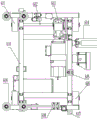
FIG. 2 is a schematic perspective view of the enclosure of FIG. 1 with the enclosure removed;
FIG. 3 is a schematic structural view of the chassis assembly of the present invention;
FIG. 4 is a second schematic structural view of the chassis assembly of the present invention;
FIG. 5 is a second schematic perspective view of the cover of FIG. 1;
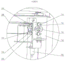
FIG. 6 is an enlarged view of a portion of FIG. 5 at A;
FIG. 7 is a schematic view of the hatch mechanism of the present invention;
FIG. 8 is a schematic structural diagram of the tipping mechanism of the present invention;
wherein: 1 is a track, 2 is a left cover plate, 4 is a top cover plate, 5 is a button control panel, 6 is a chassis component, 601 is a main driving wheel, 602 is a driving shaft, 603 is a driving motor A, 604 is a power taking device, 605 is an anti-tipping device, 606 is a follower wheel, 607 is a safety scanner, 608 is a wireless communication antenna, 609 is a guide wheel component, 610 is a chassis frame, 611 is a bearing mounting rack, 612 is an anti-tipping bearing, 613 is a bearing seat A, 614 is a guide wheel, 615 is a fixing plate, 7 is a cabin door mechanism, 701 is a cabin door cover plate, 702 is a photoelectric switch, 703 is a driving synchronous pulley, 704 is a motor mounting bracket, 705 is a clamping bracket, 706 is a stepping motor, 707 is a slide rail, 708 is a synchronous toothed belt, 709 is a tensioning device, 710 is a follower synchronous pulley, 711 is a tensioning bolt, 712 is a tensioning nut, 713 is a mounting plate, 714 is a strip-shaped hole, 715 is a fastening bolt, 716 is a waist hole, 717 is a baffle, 718 is a welding plate, 8 is a tipping mechanism, 801 is a bearing seat B, 802 is a driving motor B, 803 is a driving arm, 804 is a hopper, 805 is a follow-up arm, 9 is a right cover plate, 10 is a controller, 11 is a vehicle body frame, 12 is a fan, 13 is a front end face, 14 is a side beam, 15 is a cross beam, and 16 is a bearing plate.
Detailed Description
The present invention will be described in further detail with reference to the accompanying drawings.
As shown in fig. 1 to 8, the present invention includes a frame, a chassis assembly 6, a hatch mechanism 7 and a tipping mechanism 8, wherein the frame is mounted on the chassis assembly 6, the hatch mechanism 7 and the frame form a closed space, and the tipping mechanism 8 is located in the closed space to prevent the external environment from polluting the transported materials.
The frame of the embodiment comprises a left cover plate 2, a top cover plate 4, a right cover plate 9 and a vehicle body frame 11, wherein the vehicle body frame 11 is mainly formed by welding stainless steel plates into a frame structure, the front end surface and the rear end surface of the vehicle body frame 11 are integral stainless steel wire drawing plates serving as the appearance surface of the vehicle body, and a button control panel 5 and a fan 12 are integrated on the front end surface 13 of the vehicle body frame 11. The left cover plate 2 and the right cover plate 9 are respectively installed on side beams 14 on the left and right sides of a vehicle body frame 11, cross beams 15 serving as bearing bodies of the hatch door mechanisms 7 are welded on the tops of the side beams 14 on the two sides, and slide rails 707 are fixed on the cross beams 15. Both sides of the roof panel 4 are mounted on the side beams 15, respectively. A bearing plate 16 is provided in the middle of the vehicle body frame 11 as a mounting plate for the controller 10.
The chassis assembly 6 of the present embodiment includes a main driving wheel 601, a driving shaft 602, a driving motor a603, a follower wheel 606 and a chassis frame 610, wherein the chassis frame 610 is a carrier of the whole shuttle vehicle, the frame is installed above the chassis frame 610, and the main driving wheel 601, the driving shaft 602, the driving motor a603 and the follower wheel 606 are respectively installed below the chassis frame 610; the main driving wheels 601 are symmetrically installed on two sides of one end of the chassis frame 610 in the walking direction, the main driving wheels 601 on two sides are connected through a driving shaft 602, two ends of the driving shaft 602 are respectively installed on the chassis frame 610 through a bearing seat A613, and the driving shaft 602 is rotatably connected with the bearing seat A613 through a bearing. The driving motor A603 is installed on the chassis frame 610, the output end of the driving motor A603 is connected with the driving shaft 602, the two sides of the other end of the chassis frame 610 in the walking direction are symmetrically provided with the following wheels 606, the wheel shafts of the following wheels 606 are installed on the chassis frame 610 through the bearing seats A613, and the wheel shafts of the following wheels 606 are rotatably connected with the bearing seats A613 through bearings. The tracks 1 are parallel, and the main driving wheel 601 and the following wheel 606 on each side of the chassis frame 610 run on one track 1. Mounting holes are reserved on two end faces of the chassis frame 610, and the chassis frame can be used for mounting lifting rings and can also be used for mounting buffers on two sides of a vehicle body.
In this embodiment, guide wheel assemblies 609 for guiding are respectively installed at the front end and the rear end of the bottom surface of one side of the chassis frame 610, the guide wheel assemblies 609 include a fixing plate 615 and guide wheels 614, the fixing plate 615 is fixedly connected to the chassis frame 610, the guide wheels 614 are rotatably installed at both ends of the fixing plate 615, and the guide wheels 614 at both ends are located at the left side and the right side of the track 1 at one side and abut against the two side surfaces of the track 1. The rail 1 of this embodiment is "i" shaped steel, the two guide wheels 614 are respectively located on two sides of the vertical edge of the "i" shaped steel, and the axial center line of the guide wheels 614 is parallel to the vertical edge of the "i" shaped steel.
In the embodiment, the other side of the chassis frame 610 is respectively provided with the power taking device 604 and the anti-tipping device 605 for preventing the shuttle vehicle from tipping, the power taking device 604 is arranged on the side surface of the other side of the chassis frame 610, and the anti-tipping device 605 is arranged on the bottom surface of the other side of the chassis frame 610; the power-taking device 604 of this embodiment is a shifting fork, one end of which is installed on the chassis frame 610, and the other end of which is inserted into the current collector on the power supply rail to supply power to the shuttle car. The fork and the current collector of this embodiment are prior art and will not be described herein. The anti-tipping device 605 includes a bearing mounting frame 611 and an anti-tipping bearing 612, one end of the bearing mounting frame 611 is fixedly connected to the chassis frame 610, the other end is provided with a connecting shaft, one end of the connecting shaft is rotatably mounted with the anti-tipping bearing 612, and the other end is tightly fastened with the bearing mounting frame 611 through a nut. The anti-tipping bearing 612 slides along the lower edge of the rail 1 at the other side, so that the tipping force can be offset, the side turning of the vehicle body is prevented, and the stable operation of the vehicle body is ensured. The axial direction of the anti-toppling bearing 612 of the present embodiment is parallel to the horizontal plane.
In the embodiment, a safety scanner 607 and a wireless communication antenna 608 are respectively installed below the front end of a chassis frame 610, and the safety scanner 607 is connected with a controller 10 to prevent a vehicle body from colliding with an obstacle during traveling; the wireless communication antenna 608 is used for wireless communication with the upper computer.
The cabin door mechanism 7 of the embodiment includes a cabin door cover plate 701, a sliding rail 707, a driving synchronous pulley 703, a clamping bracket 705, a stepping motor 706, a synchronous cog belt 708 and a follow-up synchronous pulley 710 which are respectively located inside a frame, wherein the sliding rail 707 is made of an aluminum alloy material, the cabin door cover plate 701 is slidably connected with the sliding rail 707 installed at the top of the frame, the driving synchronous pulley 703 and the follow-up synchronous pulley 710 are respectively installed inside the frame and connected through the synchronous cog belt 708, and the driving synchronous pulley 703 and the follow-up synchronous pulley 710 are arranged along the length direction of the sliding rail 707; the stepping motor 706 is fixed on the side panel in the vehicle body frame 11 through a motor mounting bracket 704, the output end of the stepping motor 706 is connected with the driving synchronous belt pulley 703, the clamping bracket 705 is mounted on the synchronous toothed belt 708, and the upper end of the clamping bracket 705 is connected with the hatch cover plate 701; the clamping bracket 705 moves along with the synchronous toothed belt 708 under the driving of the stepping motor 706, so as to drive the cabin door cover plate 701 to slide along the sliding rail 707, and realize the opening and closing of the cabin door; when the hatch cover 701 is in the closed position, the hatch cover 701 is positioned above between the driving timing pulley 703 and the follower timing pulley 710. In the embodiment, photoelectric switches 702 mounted on the vehicle body frame 11 are arranged below the driving synchronous pulley 703 and the following synchronous pulley 710, and the two photoelectric switches 702 are symmetrically arranged and are respectively connected with the controller 10; the lower end of the clamping bracket 705 is provided with a baffle 717 corresponding to the photoelectric switch 702.
In this embodiment, a tensioning device 709 is disposed on one side of the driven synchronous pulley 710, the tensioning device 709 includes a tensioning bolt 711, a tensioning nut 712, a mounting plate 713, a fastening bolt 715 and a welding plate 718, the welding plate 718 is welded to the body frame 11, a strip hole 714 and a waist hole 716 are respectively formed in the welding plate 718, the waist hole 716 is one, and two strip holes 714 are symmetrically formed in the upper and lower sides of the waist hole 716. The surface of one side of the welding plate 718 facing the follow-up synchronous pulley 710 is provided with an installation plate 713, and the upper end and the lower end of the installation plate 713 are fixedly connected to the welding plate 718 through a fastening bolt 715; each fastening bolt 715 is inserted into one strip-shaped hole 714, and after the position is adjusted, the fastening bolts 715 are screwed and fixed. The axle of the follower timing pulley 710 is mounted in the middle of the mounting plate 713, the axle of the follower timing pulley 710 is located between the two fastening bolts 715, and the waist hole 716 provides a space for mounting and dismounting the axle of the follower timing pulley 710. A tensioning nut 712 is fixedly connected to the welding plate 718, a tensioning bolt 711 is connected to the tensioning nut 712 in a threaded manner, and the tensioning bolt 711 abuts against the side face of the mounting plate 713; the number of the tensioning bolts 711 and the tensioning nuts 712 in this embodiment is two, and the two are arranged up and down.
The top of the frame of this embodiment is closed on one side and open on the other side, the opening being closed by a hatch cover plate 701 sliding on a sliding rail 707; the tipping mechanism 8 is positioned below the cabin door cover plate 701 when the open position of the vehicle frame is in a closed state, the tipping mechanism 8 comprises a driving motor B802, a driving arm 803, a hopper 804 and a follower arm 805, the driving motor B802 is arranged on a chassis frame 610 of the chassis assembly 6, the output end of the driving motor B802 is hinged with one end of the driving arm 803, and the other end of the driving arm 803 is hinged with the bottom of the hopper 804; one end of the follower arm 805 is hinged on a bearing seat B801 arranged on the chassis frame 610 of the chassis assembly 6, and the other end of the follower arm 805 is hinged with the bottom of the hopper 804; the driving motor B802, the driving arm 803, the follower arm 805 and the bearing seat B801 form a link mechanism, the driving motor B802 drives the hopper 804 through the driving arm 803 and the follower arm 805 to realize posture position adjustment, the hopper is kept horizontal at an original position, and the required overturning and dumping height is achieved at a dumping position.
The working principle of the invention is as follows:
the upper computer transmits a signal of the shuttle car walking to a destination to the controller 10 through the wireless communication antenna 608, the controller 10 controls the driving motor A603 to work to provide power, the driving shaft 602 drives the main driving wheel 601, so that the car body runs along the track 1, and the follow-up wheel 606 follows up; the guide wheel assembly 609 abuts against the track 1 through the guide wheel 614 to guide the vehicle body; the anti-tipping device 605 can resist the tipping force by means of the anti-tipping bearing 612 sliding with the lower edge of the track 1, so as to prevent the vehicle body from tipping. During the operation of the vehicle body, the hatch cover plate 701 is closed to form a closed space so as to prevent the pollution of the external environment to the conveyed materials. The safety scanner 607 is positioned and operated to a designated station by scanning the bar code, and after the station is reached, the controller 10 controls the driving motor A603 to stop working; then, the controller 10 controls the stepping motor 706 to operate, and the clamping bracket 705 drives the hatch cover plate 701 to gradually open through the transmission of the driving synchronous pulley 703, the following synchronous pulley 710 and the synchronous cog belt 708. When the baffle 717 at the lower end of the clamping bracket 705 moves to the position above the photoelectric switch 702 below the driving synchronous pulley 703, the photoelectric switch 702 transmits a signal to the controller 10, and the controller 10 controls the stepping motor 706 to stop working.
The controller 10 controls the driving motor B802 to work, and under the driving of the driving arm 803 and the follower arm 805, the hopper 804 can realize turning motion, and can reach the required height and inclination angle at the designated position, so that the material loaded in the hopper 804 can be poured out; after the dumping is finished, the hopper 804 is driven by the driving motor B802 in the reverse direction, and is retracted into the vehicle body frame 11 by the driving arm 803 and the follower arm 805.
The controller 10 controls the stepping motor 706 to work reversely, and the clamping bracket 705 drives the cabin door cover plate 701 to close gradually through the transmission of the driving synchronous pulley 703, the following synchronous pulley 710 and the synchronous cog belt 708. When the baffle 717 at the lower end of the clamping bracket 705 moves above the photoelectric switch 702 below the follower timing pulley 710, the photoelectric switch 702 transmits a signal to the controller 10, and the controller 10 controls the stepping motor 706 to stop operating.
Then, the controller 10 controls the drive motor a603 to move the shuttle to the next station.