CN110831737B - Plastic injection molding machine and molding method - Google Patents
Plastic injection molding machine and molding method Download PDFInfo
- Publication number
- CN110831737B CN110831737B CN201780092644.XA CN201780092644A CN110831737B CN 110831737 B CN110831737 B CN 110831737B CN 201780092644 A CN201780092644 A CN 201780092644A CN 110831737 B CN110831737 B CN 110831737B
- Authority
- CN
- China
- Prior art keywords
- platen
- movable
- locking
- fixed central
- movable platen
- Prior art date
- Legal status (The legal status is an assumption and is not a legal conclusion. Google has not performed a legal analysis and makes no representation as to the accuracy of the status listed.)
- Active
Links
Images


Classifications
-
- B—PERFORMING OPERATIONS; TRANSPORTING
- B29—WORKING OF PLASTICS; WORKING OF SUBSTANCES IN A PLASTIC STATE IN GENERAL
- B29C—SHAPING OR JOINING OF PLASTICS; SHAPING OF MATERIAL IN A PLASTIC STATE, NOT OTHERWISE PROVIDED FOR; AFTER-TREATMENT OF THE SHAPED PRODUCTS, e.g. REPAIRING
- B29C45/00—Injection moulding, i.e. forcing the required volume of moulding material through a nozzle into a closed mould; Apparatus therefor
- B29C45/17—Component parts, details or accessories; Auxiliary operations
- B29C45/26—Moulds
- B29C45/32—Moulds having several axially spaced mould cavities, i.e. for making several separated articles
-
- B—PERFORMING OPERATIONS; TRANSPORTING
- B29—WORKING OF PLASTICS; WORKING OF SUBSTANCES IN A PLASTIC STATE IN GENERAL
- B29C—SHAPING OR JOINING OF PLASTICS; SHAPING OF MATERIAL IN A PLASTIC STATE, NOT OTHERWISE PROVIDED FOR; AFTER-TREATMENT OF THE SHAPED PRODUCTS, e.g. REPAIRING
- B29C45/00—Injection moulding, i.e. forcing the required volume of moulding material through a nozzle into a closed mould; Apparatus therefor
- B29C45/17—Component parts, details or accessories; Auxiliary operations
- B29C45/1742—Mounting of moulds; Mould supports
- B29C45/1744—Mould support platens
-
- B—PERFORMING OPERATIONS; TRANSPORTING
- B29—WORKING OF PLASTICS; WORKING OF SUBSTANCES IN A PLASTIC STATE IN GENERAL
- B29C—SHAPING OR JOINING OF PLASTICS; SHAPING OF MATERIAL IN A PLASTIC STATE, NOT OTHERWISE PROVIDED FOR; AFTER-TREATMENT OF THE SHAPED PRODUCTS, e.g. REPAIRING
- B29C45/00—Injection moulding, i.e. forcing the required volume of moulding material through a nozzle into a closed mould; Apparatus therefor
- B29C45/17—Component parts, details or accessories; Auxiliary operations
- B29C45/1761—Means for guiding movable mould supports or injection units on the machine base or frame; Machine bases or frames
-
- B—PERFORMING OPERATIONS; TRANSPORTING
- B29—WORKING OF PLASTICS; WORKING OF SUBSTANCES IN A PLASTIC STATE IN GENERAL
- B29C—SHAPING OR JOINING OF PLASTICS; SHAPING OF MATERIAL IN A PLASTIC STATE, NOT OTHERWISE PROVIDED FOR; AFTER-TREATMENT OF THE SHAPED PRODUCTS, e.g. REPAIRING
- B29C45/00—Injection moulding, i.e. forcing the required volume of moulding material through a nozzle into a closed mould; Apparatus therefor
- B29C45/17—Component parts, details or accessories; Auxiliary operations
- B29C45/46—Means for plasticising or homogenising the moulding material or forcing it into the mould
- B29C45/47—Means for plasticising or homogenising the moulding material or forcing it into the mould using screws
- B29C45/50—Axially movable screw
- B29C45/5008—Drive means therefor
-
- B—PERFORMING OPERATIONS; TRANSPORTING
- B29—WORKING OF PLASTICS; WORKING OF SUBSTANCES IN A PLASTIC STATE IN GENERAL
- B29C—SHAPING OR JOINING OF PLASTICS; SHAPING OF MATERIAL IN A PLASTIC STATE, NOT OTHERWISE PROVIDED FOR; AFTER-TREATMENT OF THE SHAPED PRODUCTS, e.g. REPAIRING
- B29C45/00—Injection moulding, i.e. forcing the required volume of moulding material through a nozzle into a closed mould; Apparatus therefor
- B29C45/17—Component parts, details or accessories; Auxiliary operations
- B29C45/64—Mould opening, closing or clamping devices
- B29C45/68—Mould opening, closing or clamping devices hydro-mechanical
-
- B—PERFORMING OPERATIONS; TRANSPORTING
- B29—WORKING OF PLASTICS; WORKING OF SUBSTANCES IN A PLASTIC STATE IN GENERAL
- B29C—SHAPING OR JOINING OF PLASTICS; SHAPING OF MATERIAL IN A PLASTIC STATE, NOT OTHERWISE PROVIDED FOR; AFTER-TREATMENT OF THE SHAPED PRODUCTS, e.g. REPAIRING
- B29C45/00—Injection moulding, i.e. forcing the required volume of moulding material through a nozzle into a closed mould; Apparatus therefor
- B29C45/17—Component parts, details or accessories; Auxiliary operations
- B29C45/1761—Means for guiding movable mould supports or injection units on the machine base or frame; Machine bases or frames
- B29C2045/1764—Guiding means between the movable mould plate and tie rods
-
- B—PERFORMING OPERATIONS; TRANSPORTING
- B29—WORKING OF PLASTICS; WORKING OF SUBSTANCES IN A PLASTIC STATE IN GENERAL
- B29C—SHAPING OR JOINING OF PLASTICS; SHAPING OF MATERIAL IN A PLASTIC STATE, NOT OTHERWISE PROVIDED FOR; AFTER-TREATMENT OF THE SHAPED PRODUCTS, e.g. REPAIRING
- B29C45/00—Injection moulding, i.e. forcing the required volume of moulding material through a nozzle into a closed mould; Apparatus therefor
- B29C45/17—Component parts, details or accessories; Auxiliary operations
- B29C45/46—Means for plasticising or homogenising the moulding material or forcing it into the mould
- B29C45/47—Means for plasticising or homogenising the moulding material or forcing it into the mould using screws
- B29C45/50—Axially movable screw
- B29C45/5008—Drive means therefor
- B29C2045/5028—Drive means therefor screws axially driven by the coaxial rotor of an electric motor
-
- B—PERFORMING OPERATIONS; TRANSPORTING
- B29—WORKING OF PLASTICS; WORKING OF SUBSTANCES IN A PLASTIC STATE IN GENERAL
- B29C—SHAPING OR JOINING OF PLASTICS; SHAPING OF MATERIAL IN A PLASTIC STATE, NOT OTHERWISE PROVIDED FOR; AFTER-TREATMENT OF THE SHAPED PRODUCTS, e.g. REPAIRING
- B29C45/00—Injection moulding, i.e. forcing the required volume of moulding material through a nozzle into a closed mould; Apparatus therefor
- B29C45/17—Component parts, details or accessories; Auxiliary operations
- B29C45/64—Mould opening, closing or clamping devices
- B29C45/66—Mould opening, closing or clamping devices mechanical
- B29C2045/665—Mould opening, closing or clamping devices mechanical using a screw or screws having differently threaded parts arranged in series
-
- B—PERFORMING OPERATIONS; TRANSPORTING
- B29—WORKING OF PLASTICS; WORKING OF SUBSTANCES IN A PLASTIC STATE IN GENERAL
- B29C—SHAPING OR JOINING OF PLASTICS; SHAPING OF MATERIAL IN A PLASTIC STATE, NOT OTHERWISE PROVIDED FOR; AFTER-TREATMENT OF THE SHAPED PRODUCTS, e.g. REPAIRING
- B29C45/00—Injection moulding, i.e. forcing the required volume of moulding material through a nozzle into a closed mould; Apparatus therefor
- B29C45/17—Component parts, details or accessories; Auxiliary operations
- B29C45/64—Mould opening, closing or clamping devices
- B29C45/67—Mould opening, closing or clamping devices hydraulic
- B29C45/6707—Mould opening, closing or clamping devices hydraulic without relative movement between the piston and the cylinder of the clamping device during the mould opening or closing movement
- B29C2045/675—Rotatable means coaxial with the tie rod for locking the movable platen to the tie rod, e.g. bayonet couplings using teeth or splines interrupted by longitudinal grooves
-
- B—PERFORMING OPERATIONS; TRANSPORTING
- B29—WORKING OF PLASTICS; WORKING OF SUBSTANCES IN A PLASTIC STATE IN GENERAL
- B29C—SHAPING OR JOINING OF PLASTICS; SHAPING OF MATERIAL IN A PLASTIC STATE, NOT OTHERWISE PROVIDED FOR; AFTER-TREATMENT OF THE SHAPED PRODUCTS, e.g. REPAIRING
- B29C45/00—Injection moulding, i.e. forcing the required volume of moulding material through a nozzle into a closed mould; Apparatus therefor
- B29C45/17—Component parts, details or accessories; Auxiliary operations
- B29C45/64—Mould opening, closing or clamping devices
- B29C45/68—Mould opening, closing or clamping devices hydro-mechanical
- B29C2045/688—Mould opening, closing or clamping devices hydro-mechanical using tie rods as separate elements for clamping
-
- B—PERFORMING OPERATIONS; TRANSPORTING
- B29—WORKING OF PLASTICS; WORKING OF SUBSTANCES IN A PLASTIC STATE IN GENERAL
- B29C—SHAPING OR JOINING OF PLASTICS; SHAPING OF MATERIAL IN A PLASTIC STATE, NOT OTHERWISE PROVIDED FOR; AFTER-TREATMENT OF THE SHAPED PRODUCTS, e.g. REPAIRING
- B29C45/00—Injection moulding, i.e. forcing the required volume of moulding material through a nozzle into a closed mould; Apparatus therefor
- B29C45/03—Injection moulding apparatus
- B29C45/04—Injection moulding apparatus using movable moulds or mould halves
- B29C45/0441—Injection moulding apparatus using movable moulds or mould halves involving a rotational movement
- B29C45/045—Injection moulding apparatus using movable moulds or mould halves involving a rotational movement mounted on the circumference of a rotating support having a rotating axis perpendicular to the mould opening, closing or clamping direction
-
- B—PERFORMING OPERATIONS; TRANSPORTING
- B29—WORKING OF PLASTICS; WORKING OF SUBSTANCES IN A PLASTIC STATE IN GENERAL
- B29C—SHAPING OR JOINING OF PLASTICS; SHAPING OF MATERIAL IN A PLASTIC STATE, NOT OTHERWISE PROVIDED FOR; AFTER-TREATMENT OF THE SHAPED PRODUCTS, e.g. REPAIRING
- B29C45/00—Injection moulding, i.e. forcing the required volume of moulding material through a nozzle into a closed mould; Apparatus therefor
- B29C45/17—Component parts, details or accessories; Auxiliary operations
- B29C45/64—Mould opening, closing or clamping devices
- B29C45/67—Mould opening, closing or clamping devices hydraulic
- B29C45/6707—Mould opening, closing or clamping devices hydraulic without relative movement between the piston and the cylinder of the clamping device during the mould opening or closing movement
-
- B—PERFORMING OPERATIONS; TRANSPORTING
- B29—WORKING OF PLASTICS; WORKING OF SUBSTANCES IN A PLASTIC STATE IN GENERAL
- B29C—SHAPING OR JOINING OF PLASTICS; SHAPING OF MATERIAL IN A PLASTIC STATE, NOT OTHERWISE PROVIDED FOR; AFTER-TREATMENT OF THE SHAPED PRODUCTS, e.g. REPAIRING
- B29C45/00—Injection moulding, i.e. forcing the required volume of moulding material through a nozzle into a closed mould; Apparatus therefor
- B29C45/17—Component parts, details or accessories; Auxiliary operations
- B29C45/64—Mould opening, closing or clamping devices
- B29C45/68—Mould opening, closing or clamping devices hydro-mechanical
- B29C45/683—Mould opening, closing or clamping devices hydro-mechanical using both a toggle mechanism as mould closing device and another mechanism as mould clamping device
Landscapes
- Engineering & Computer Science (AREA)
- Manufacturing & Machinery (AREA)
- Mechanical Engineering (AREA)
- Injection Moulding Of Plastics Or The Like (AREA)
- Moulds For Moulding Plastics Or The Like (AREA)
Abstract
本发明涉及塑料注射成型机械和成型方法,更具体地涉及用于叠层模具的注射成型机械,其中模具的中心部分保持稳定,并且模具有两个成型面,该两个成型面借助于产生夹紧力的液压腔室而作用在稳定中心部分上,并防止由于成型面上的弯曲而引起的变形。本发明还涉及成型方法。

The present invention relates to a plastic injection molding machine and a molding method, and more particularly to an injection molding machine for a laminated mold, in which the center portion of the mold is held stable and the mold has two molding surfaces, which are produced by means of a clamp The tight hydraulic chamber acts on the stabilizing center portion and prevents deformation due to bending of the forming surface. The invention also relates to a molding method.
Description
技术领域technical field
本发明涉及用于使用注射成型方法制造塑料工件的机械以及成型方法,该机械改进了使用注射成型机械的系统以将其与简单模具或叠层模具一起使用。更具体地,本发明的机械对象特别适用于使用多腔室模具的包装、食品、卫生等行业的较大系列工件的制造,以及适用于其形状大致对称的较小系列的成对工件中,例如用于汽车行业的前后保险杠或左右门板等。The present invention relates to a machine for the manufacture of plastic workpieces using an injection molding method and a molding method, the machine improving a system using an injection molding machine for use with a simple mold or a stack mold. More specifically, the mechanical object of the present invention is particularly suitable for the manufacture of larger series of workpieces in the packaging, food, hygiene and other industries using multi-chamber molds, as well as in smaller series of paired workpieces whose shapes are roughly symmetrical, For example, front and rear bumpers or left and right door panels are used in the automotive industry.
本发明属于针对塑料部件的注射成型的机械领域。The invention belongs to the field of machinery for injection moulding of plastic parts.
背景技术Background technique
通常,塑料注射成型机械具有:固定(stationary)压板和活动压板,构成模具的两个半部中的各个固定在其上;以及后压板,其结构功能是承受必要的力以在成型过程期间保持模具闭合。它们是庞大的机械,需要相当大的空间来放置它们,并且在打开和闭合模具时需要使其进行运动的质量增加,这不利地影响了循环时间。模具的尺寸决定了机械的尺寸和所需的夹紧力,该力与注射表面成比例。夹紧力和压板的尺寸越大,由于它们的弯曲应力而引起的变形能够增加得越多,结果,在模具闭合不良的最终工件中出现飞边。Typically, a plastic injection molding machine has: a stationary platen and a movable platen, on which each of the two halves that make up the mold is fixed; and a rear platen, whose structural function is to withstand the necessary forces to hold during the molding process The mold is closed. They are bulky machines that require considerable space to place them and the increased mass required to move the mold when opening and closing the mold adversely affects cycle times. The size of the mold determines the size of the machine and the required clamping force, which is proportional to the injection surface. The larger the clamping force and the size of the platen, the more the deformation due to their bending stress can increase, and as a result, flash appears in the final workpiece with poor mold closure.
对于用于小工件的多腔室模具特别有用的是叠层式模具,由于它们具有两个成型面,所以使得能够减少投射在机械板上的模具表面,使得在不需要增加夹紧力的情况下,生产能力能够成倍增加或模具的尺寸能够降低。总之,叠层模具由两个侧面部分和具有两个成型面的中心部分组成,各个成型面面向侧面部分中的各个。Particularly useful for multi-chamber molds for small workpieces are stack molds, since they have two forming faces, which enable a reduction of the mold surface projected on the machine plate, without the need to increase the clamping force Under these conditions, the production capacity can be multiplied or the size of the mold can be reduced. In summary, the stack mold consists of two side parts and a central part with two forming surfaces, each forming surface facing each of the side parts.
在现有技术中,有许多描述了用于叠层模具的机械或实行方式的文献,其中,模具的一侧接合到固定压板上,而另一侧接合到活动压板上,并且中心部分通过某种复杂的机制伴随着活动压板的运动。在这种情况下,当将总打开行程与如果独立打开其将会是的情况(例如通过保持中心部固定并移动侧面中的各个侧面)相比时,总打开行程需要是各个模具表面的单个打开行程的两倍,并且对打开时间产生两倍的不利影响。In the prior art, there are many documents describing machines or implementations for stacking molds in which one side of the mold is joined to a fixed platen and the other to a movable platen, and the central part is A complex mechanism accompanies the movement of the movable platen. In this case, when comparing the total opening stroke to what it would be if opened independently (eg by keeping the center fixed and moving each of the sides), the total opening stroke needs to be a single Twice the opening stroke and have twice the detrimental effect on opening time.
此外,熔融聚合物的添加通常通过固定压板进行,这在设计模具的供应时导致很大的复杂性,难以在模具的不同部分和被减少的模具表面中保证材料的相同条件,并且因此减少了图形的数量。文献US4207051示出了一种类型的配置,其中,在中心部分进行注射,但是每次打开模具时需要使用复杂的、昂贵的伸缩系统,或者需要收回注射系统。In addition, the addition of molten polymer is usually carried out by means of a stationary platen, which leads to great complexity in designing the supply of the mould, it is difficult to ensure the same condition of the material in the different parts of the mould and the reduced mould surface, and therefore reduces the the number of graphics. Document US4207051 shows a type of configuration in which the injection takes place in the central part, but requires the use of a complex, expensive telescoping system each time the mould is opened, or the injection system needs to be retracted.
此外,在完成模具打开运动前,无法提取工件。鉴于此,为了进行模具的打开,活动压板和中心部分在相同方向上且同时移动;如果在完成打开运动之前取出在附接到活动板的侧面部分与中心部分之间的模具腔室中制成的工件,则中心部分将与成型工件发生碰撞。在开始打开运动的同时进行成型工件的提取将是非常有利的,因为这将减少循环时间。此外,工件提取被中心部分的进料通道中断,这将使工件与其碰撞。In addition, the workpiece cannot be extracted until the mold opening movement has been completed. In view of this, in order to carry out the opening of the mould, the movable platen and the central part are moved in the same direction and at the same time; the workpiece, the center part will collide with the forming workpiece. It would be very advantageous to carry out the extraction of the formed workpiece at the same time as the opening movement was started, as this would reduce the cycle time. In addition, workpiece extraction is interrupted by the feed channel of the central section, which will cause workpieces to collide with it.
以下文献ES8406291、FR1304803、FR2294041、WO9748540和JPS627521涉及用于叠层模具的注射机械,其中心部分保持稳定(fixed)。所有这些都具有带有两个活动压板的两个后压板,在这种情况下其涉及庞大的设备,或者具有带有两个活动压板的单个后活动压板,在这种情况下,活动质量增加了,而且此外,通常由于两个活动板的闭合行程不能同时进行的事实,闭合操作的时间也增加了。此外,在后一种情况下,当由于活动后压板的运动而产生闭合时,它总是增加机械的长度。The following documents ES8406291, FR1304803, FR2294041, WO9748540 and JPS627521 relate to injection machines for stack moulds, the central part of which remains fixed. All of these have two rear moving platens with two moving platens, in which case it involves bulky equipment, or a single rear moving platen with two moving platens, in which case the moving mass increases Furthermore, the time for the closing operation is also increased, usually due to the fact that the closing strokes of the two flaps cannot be carried out simultaneously. Furthermore, in the latter case, it always increases the length of the machine when closing due to the movement of the movable rear platen.
文献FR2295832没有用于施加夹紧力的后压板。一旦将端板放在一起,就用夹具阻挡拉杆,并通过位于实行方式1和3中在自身的拉杆或在中心固定压板中的液压缸施加力。在任何实施方式中,拉杆都接合到两个活动压板中的一个,并且因此,除了由拉杆本身的运动增加了机械的长度的事实外,它们还增加了活动质量的量,增加了操作时间和/或能耗。Document FR2295832 does not have a rear pressure plate for applying the clamping force. Once the end plates are put together, the tie rods are blocked with clamps and the force is applied by means of the tie rods themselves or the hydraulic cylinders in the central fixed platen in
在所有前述情况下,都会出现另一问题。众所周知,在施加夹紧力时,由于活动板并且特别是固定板的弯曲应力而产生显著的变形。这致使模具的部分不能完美地闭合在一起,导致飞边和缺陷工件的形成。通常,模具越大,拉杆之间的距离就需要更大,并且将形成更大变形的夹紧力越大,因此需要更厚的板,并且因此活动质量更大。In all the aforementioned cases, another problem arises. It is known that when clamping forces are applied, significant deformations occur due to the bending stresses of the movable and in particular the stationary plates. This results in the parts of the mold not closing together perfectly, leading to the formation of flash and defective workpieces. In general, the larger the die, the greater the distance between the tie rods and the greater the clamping force that will create the greater deformation, thus requiring a thicker plate, and therefore more active mass.
消除由于弯曲应力而引起的变形的一种方法是如在文献的一部分中所描述的,其中,中心部分保持固定,其中,由于在侧面上施加了夹紧力,反作用力被平衡,所以消除了该板上由于弯曲应力引起的变形。然而,由于弯曲应力而引起的变形继续出现在活动压板上。One way to eliminate the deformation due to bending stress is as described in part of the literature, where the central part remains fixed, where the reaction force is balanced due to the clamping force applied on the sides, so eliminating Deformation of the plate due to bending stress. However, deformation due to bending stress continued to occur on the movable platen.
文献ES2162013、WO03/084731、US6027329、US6439876和US2008/0175938描述了具有不同几何形状的一系列模具固定板,这些模具固定板或多或少是复杂的,其目的是消除接合到模具的压板的面上的挠曲变形,并且因此模具表面保持平坦。该解决方案的缺点之一是,为了使几何形状有效地起作用,需要较大的活动压板厚度。此外,单个几何形状不是对于施加任何夹紧力都有效的,因此,需要为各个几何形状限定一系列应用范围。Documents ES2162013, WO03/084731, US6027329, US6439876 and US2008/0175938 describe a series of mould holding plates with different geometries, these mould holding plates are more or less complex, the purpose of which is to eliminate the face of the pressure plate which is joined to the mould flexural deformation on, and thus the mold surface remains flat. One of the drawbacks of this solution is that a large movable platen thickness is required for the geometry to function effectively. Furthermore, a single geometry is not effective for applying any clamping force, so a range of applications needs to be defined for each geometry.
在叠层模具中,它们特别有利于用于生产需要使用两种不同材料和立方体模具的工件。这些通常是叠层式模具,如前所述,其中,中心部分除了线性移动外,还可以旋转。在能够旋转时,它们可以具有多个成型面,通常为四个(然而不限于此数量),在注射过程中同时使用两个。在模具的部分的一个中,利用一种类型的材料注射工件,而在另一部分中,将第二类型的材料沉积在位于相对面内部且预先在另一部分中成型的工件上。不需要更多的操作细节,因为这对于那些与该技术领域有关的人来说意味着足够了。中心部分不仅具有旋转运动,而且还具有必须被线性移动才能进行打开和闭合的非常高的质量,并且这会形成必须使其进行运动的较大质量,这不利地影响循环时间和能耗。此外,这需要必须通过端板完成注射,单元中的一个被放置在活动板上,这甚至增加了要移动的质量。In stack molds, they are particularly advantageous for producing workpieces that require the use of two different materials and cube molds. These are usually stacked dies, as previously mentioned, where the central part can be rotated in addition to linear movement. When rotatable, they can have multiple molding surfaces, typically four (but not limited to this number), with two being used simultaneously during the injection process. In one of the parts of the mold, the workpiece is injected with one type of material, while in the other a second type of material is deposited on the workpiece that is inside the opposite face and preformed in the other part. No more operational details are needed, as this means enough for those involved in this technical field. The central part not only has a rotational movement, but also has a very high mass that must be moved linearly for opening and closing, and this creates a large mass that must be moved, which adversely affects cycle time and energy consumption. Furthermore, this requires that the injection has to be done through the end plate, one of the units is placed on the movable plate, which even increases the mass to be moved.
所引用的文献中均未涉及通过系统本身施加夹紧力来减小弯曲偏转的影响的系统。这种类型的系统,例如本发明的目的,使得能够使用轻质板并减小尺寸,这进一步有利于循环时间并减小机械的尺寸。所有这些考虑叠层式模具,其中,模具本身可以集成在机械内部,具有稳定中心部分,该中心部分就是模具的固定部分,其接收进料,并且具有最小的尺寸,其中,减少了诸如后压板的部件,例如,只有两个活动端板处于运动状态并且减小了尺寸。None of the cited documents refer to a system that reduces the effects of bending deflection by applying a clamping force by the system itself. This type of system, such as the object of the present invention, enables the use of lightweight panels and reduced size, which further facilitates cycle time and reduces the size of the machine. All this considers a stacked mold, where the mold itself can be integrated inside the machine, with a stable central part, which is the fixed part of the mold, which receives the feed, and has minimal dimensions, where, for example, the back platen is reduced The components, for example, have only two movable end plates in motion and are reduced in size.
发明内容SUMMARY OF THE INVENTION
本发明的主要目的之一是在最短的时间内生产尽可能最多的工件,并且为此,基于叠层模具使用机械配置,在该叠层模具中布置有固定中心压板,并在固定中心压板两侧具有相对的两个成型面。因此,除了增加产量外,还减少了能量消耗,因此提高了生产率。本发明的第二目的是通过本发明的机械对象进行的成型方法。One of the main purposes of the present invention is to produce as many workpieces as possible in the shortest time, and for this purpose, a mechanical configuration is used based on a stack mold in which a fixed central platen is arranged and two sides of the fixed central platen are arranged. The sides have two opposite molding surfaces. Therefore, in addition to increasing production, energy consumption is also reduced and thus productivity is increased. The second object of the present invention is a molding method by the mechanical object of the present invention.
因此,本发明的机械包括固定中心板,在所述中心板的至少两个相对的侧上具有至少两个成型面,并且其连接到注射单元,该注射单元向与两个活动压板相互作用的机械提供成型材料,该两个活动压板位于固定中心压板的各个侧,并且可以在相同的线性轴线上移动,以便面向固定中心压板的成型面。各个活动压板还包括:锁定系统,该锁定系统防止在施加夹紧力时活动压板的线性运动;压力板,该压力板面向固定中心压板的成型面;至少一个活动板;至少一个液压腔室,其位于活动板与压力板之间,通过用于将流体添加到所述腔室以及排出所述腔室的管道连接到液压系统;以及所述活动压板的运动系统。模具的不同部分可以接合到中心压板和各个活动压板中的压力板,或者可以集成到这些部分中。Therefore, the machine of the present invention comprises a fixed central plate with at least two moulding surfaces on at least two opposite sides of said central plate and which is connected to an injection unit which is directed towards the interface which interacts with the two movable platens The machine provides the forming material, the two movable platens are located on each side of the fixed center platen and can be moved on the same linear axis so as to face the forming surface of the fixed center platen. Each movable platen also includes: a locking system that prevents linear movement of the movable platen when clamping force is applied; a pressure plate facing the molding surface of the fixed center platen; at least one movable plate; at least one hydraulic chamber, It is located between the movable platen and the pressure plate and is connected to the hydraulic system through pipes for adding fluid to and from the chamber; and to the movement system of the movable platen. Different parts of the mold can be joined to the center platen and the pressure plates in each movable platen, or can be integrated into these parts.
中心板是固定的事实意味着它不能沿与活动压板相同的运动轴线移动,然而,如果中心板可以相对于垂直于活动压板的所述线性运动轴线的轴线活动,尤其是,相对于垂直于用于活动压板的运动的轴线的所述轴线旋转。以这种方式,在机械的中心板上可以有两个以上的成型面,成为立方体模具配置。The fact that the central plate is fixed means that it cannot move along the same axis of motion as the movable platen, however, if the central plate is movable relative to an axis perpendicular to said axis of linear motion of the movable platen, in particular, Said axis is rotated about the axis of movement of the movable platen. In this way, there can be more than two forming surfaces on the center plate of the machine, resulting in a cubic mold configuration.
由于固定中心压板是稳定的并且活动压板可以利用在两个压板上同时进行的单个线性的打开和闭合运动来移动的事实,所以在固定中心压板的两侧形成的夹紧力相等,以这种方式,当形成组件或块并且中心板在两侧被压缩相同的量时,在附接到固定中心板的模具部分中不会产生弯曲。直到施加夹紧力为止,活动压板借助于运动系统移动。Due to the fact that the fixed center platen is stable and the movable platen can be moved with a single linear opening and closing movement made simultaneously on both platens, the clamping forces developed on both sides of the fixed center platen are equal, with this In this way, when the assembly or block is formed and the center plate is compressed by the same amount on both sides, no bending occurs in the part of the mold that is attached to the fixed center plate. Until the clamping force is applied, the movable platen is moved by means of the kinematic system.
利用牢固地接合到固定中心压板的注射和塑化单元在机械的一侧上进行成型材料的供应。因此,避免了使用通常在现有技术的机械中使用的液压缸或其它活动紧固系统。该注射和塑化单元可以以任何取向布置,优选地,注射轴线是水平的且垂直于活动压板的运动轴线,或者是水平的且平行于所述轴线,甚至竖直地安装。The supply of molding material is carried out on one side of the machine by means of an injection and plasticizing unit that is firmly joined to the stationary central platen. Thus, the use of hydraulic cylinders or other movable fastening systems commonly used in prior art machines is avoided. The injection and plasticization unit can be arranged in any orientation, preferably the injection axis is horizontal and perpendicular to the movement axis of the movable platen, or horizontal and parallel to said axis, or even vertically mounted.
为了进行模具的闭合,运动系统首先致使活动压板借助于电动或液压致动器移动。为了使运动尽可能快速地进行,使活动质量减小是非常重要的。如前所述,在本发明中,活动质量限于活动压板。In order to carry out the closing of the mould, the kinematic system first causes the movable platen to move by means of electric or hydraulic actuators. In order to make the movement as fast as possible, it is very important to reduce the active mass. As mentioned above, in the present invention, the movable mass is limited to the movable platen.
闭合模具后,借助于锁定系统阻挡活动板。所述锁定优选地抵靠平行于活动压板的运动轴线的锁定连杆进行。因此,在施加夹紧力期间,拉杆不允许活动压板移动,并以这种方式使夹紧力在成型面之间有效。After closing the mould, the movable plate is blocked by means of a locking system. Said locking preferably takes place against a locking link parallel to the movement axis of the movable platen. Therefore, during the application of the clamping force, the tie rod does not allow the movable platen to move and in this way makes the clamping force effective between the profiled surfaces.
为了施加夹紧力,其具有在活动板与压力板之间的具有流体的液压腔室,使得在受控压力下将流体添加到所述腔室中时,各个活动压板试图拉伸上述锁定拉杆,而各个压力板都抵靠固定中心压板的成型面致动。压力板的与流体接触的面需要具有与成型面相似的尺寸。因此,在活动板中获得的变形无关紧要,因为由于施加在压力板上的压力相等,所以在所述压力板上的致动产生了均匀的力,并且没有产生挠曲(flexure)变形。因此,既不会由于液压腔室而在压力板中产生弯曲变形也不会由于两个压力板所产生的压缩而在固定中心压板中产生弯曲变形,因此,提高了所获得的工件的质量,消除或减少了可能导致该工件被淘汰的飞边的产生。In order to apply the clamping force, it has a hydraulic chamber with fluid between the movable plate and the pressure plate, so that when fluid is added to the chamber under controlled pressure, each movable pressure plate tries to stretch the above-mentioned locking lever , while each pressure plate is actuated against the forming surface of the fixed central pressure plate. The face of the pressure plate that is in contact with the fluid needs to be of a similar size to the forming face. Therefore, the deformation obtained in the movable plate does not matter, since the actuation on the pressure plate produces a uniform force and no flexure deformation due to the equal pressure exerted on the pressure plate. Therefore, neither bending deformation occurs in the pressure plate due to the hydraulic chamber nor in the fixed center pressure plate due to the compression generated by the two pressure plates, therefore, the quality of the obtained workpiece is improved, Eliminates or reduces the generation of flash that can cause the workpiece to be rejected.
本发明使得能够省去后压板,实现了机械的长度的减小,并且不会对活动质量有不利影响或者不会由于板的变形的影响而降低工件的质量。The invention makes it possible to omit the rear platen and achieve a reduction in the length of the machine without adversely affecting the active mass or reducing the quality of the workpiece due to the influence of the deformation of the plate.
通过这种机械配置,可以将型芯或型腔模糊地定位在放置在固定中心压板或放置在活动压板中的模具部分中。With this mechanical configuration, cores or cavities can be vaguely positioned in mold sections placed either in a fixed center platen or in a movable platen.
优选地,由运动系统致动的活动压板沿着抵接在底盘上的引导件移动。固定中心板也稳定在此底盘上。工件的提取优选地从模具的下部进行。本发明的机械使得能够在仅一次注射射料中制造任何尺寸的至少两个工件(在固定中心压板的各个侧上有一个),改变了机械的尺寸。Preferably, the movable platen, actuated by the kinematic system, moves along guides abutting on the chassis. The fixed center plate is also stabilized on this chassis. The extraction of the workpiece is preferably carried out from the lower part of the mould. The machine of the present invention enables the manufacture of at least two workpieces of any size (one on each side of the stationary center platen) in only one shot shot, varying the size of the machine.
在较大工件的特定情况下,由于不需要底盘,而是导轨(活动板在该导轨上滑动)直接紧靠在地板中的引导件上,所以进一步简化了机械的配置。在这种情况下,并且由于无法执行从下部提取工件的事实,可以在固定中心压板的上面上安装自动或手动的工件提取系统,以向上竖直提取工件。另一种可能的另选方式是安装自动工件提取系统,该系统可以对工件进行侧面提取。在任何情况下,这对于制造大尺寸工件来说都是非常有利的配置。In the specific case of larger workpieces, the configuration of the machine is further simplified since a chassis is not required, but the guide rails on which the movable plate slides directly against guides in the floor. In this case, and due to the fact that it is not possible to perform the extraction of the workpiece from the lower part, it is possible to install an automatic or manual workpiece extraction system on the upper surface of the fixed central platen to extract the workpiece vertically upwards. Another possible alternative is to install an automatic workpiece extraction system that allows side extraction of workpieces. In any case, this is a very advantageous configuration for the manufacture of large-sized workpieces.
为了更加清楚,下面将解释根据本发明的成型方法。机械跟随的阶段将从作为循环开始的开模位置开始。首先,产生通过运动系统启动的活动压板的运动,使得各个活动压板中的压力板与包括在固定中心压板中的成型面中的各个成型面接触。各个板同时沿相对的方向移动。一旦到达该位置,则借助于锁定或阻挡系统执行活动板的阻挡,该锁定或阻挡系统在施加夹紧力的时刻保持活动板的运动。然后,以双重目的将流体添加到液压腔室中,一方面施加必要的夹紧力以使模具在注射期间不会打开,而另一方面使压力板保持无挠曲变形。一旦建立了夹紧力,就利用来自注射单元的塑料填充模具。一旦完成该步骤,然后对在模具中成型的工件进行冷却,并且然后排出包含在液压腔室中的流体。然后,必须解锁锁定系统的活动板,换句话说,开始解锁拉杆的活动板,使得拉杆允许活动板在打开和闭合方向上平移。最后阶段包括活动压板远离固定中心压板的运动。该最后阶段优选地用于进行工件从模具的取出。For greater clarity, the molding method according to the present invention will be explained below. The phase of mechanical follow will start from the mold opening position as the cycle start. First, the movement of the movable platen initiated by the motion system is generated so that the pressure plate in each movable platen is brought into contact with each of the forming surfaces included in the fixed central platen. The plates move in opposite directions at the same time. Once this position is reached, the blocking of the movable panel is carried out by means of a locking or blocking system which maintains the movement of the movable panel at the moment of application of the clamping force. The fluid is then added to the hydraulic chamber with the dual purpose of applying the necessary clamping force so that the mould does not open during injection and on the other hand keeping the pressure plate free of deflection. Once the clamping force is established, the mould is filled with plastic from the injection unit. Once this step is completed, the workpiece formed in the mold is then cooled and the fluid contained in the hydraulic chamber is then discharged. Then, the movable panel of the locking system has to be unlocked, in other words, the movable panel of the pull rod must be unlocked, so that the pull rod allows the movable panel to translate in the opening and closing directions. The final stage involves the movement of the movable platen away from the fixed central platen. This final stage is preferably used to carry out the removal of the workpiece from the mould.
在下面的详细描述和附图中解释了本发明的机械的其它细节,例如其它特性、其部件的变化、其其它目的和优点。Further details of the machine of the present invention, such as other characteristics, variations of its components, its other objects and advantages, are explained in the following detailed description and drawings.
附图说明Description of drawings
描述了有助于更好地理解本发明并且与本发明的实施方式明确相关的以下附图,其示出了例示性而非限制性的示例。The following drawings, which are helpful for a better understanding of the invention and which are clearly related to the embodiments of the invention, are described, showing illustrative and non-limiting examples.
图1示出了本发明的处于闭模位置的注射机械对象的第一实施方式的立体图。Figure 1 shows a perspective view of a first embodiment of an injection machine object of the present invention in a closed mold position.
图2示出了本发明的处于开模位置的注射机械对象的侧视图。为了更清楚,部分地示出了注射单元。Figure 2 shows a side view of the injection machine object of the present invention in an open mold position. The injection unit is partially shown for greater clarity.
图3示出了用于活动压板的打开和闭合运动的实施方式的第一运动系统的致动的局部剖切部分的细节的立体图。Figure 3 shows a perspective view of a detail of a partially cutaway portion of the actuation of the first movement system for an embodiment of the opening and closing movement of the movable platen.
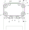
图4示出了根据图2的截面A-A的正视图,其中,活动压板的面是从固定中心压板观察的。Fig. 4 shows a front view of section A-A according to Fig. 2, wherein the face of the movable platen is viewed from the fixed central platen.
图5示出了根据图2中所示的截面B-B转过90°的示意性截面图,其示出了涉及模具闭合的元件。为了对系统进行更清晰的描述,利用特意较大的变形绘制一些元件。FIG. 5 shows a schematic cross-sectional view turned through 90° according to the section B-B shown in FIG. 2 , showing the elements involved in the closing of the mold. For a clearer description of the system, some elements are drawn with deliberately large deformations.
图6示出了根据图7中所示的截面C-C的,穿过止动杆的区域的活动板和压力板的横截面图。FIG. 6 shows a cross-sectional view of the movable plate and the pressure plate through the area of the stop lever according to the section C-C shown in FIG. 7 .
图7示出了锁定系统的第一示例的立体图中的细节。Figure 7 shows a detail in a perspective view of a first example of a locking system.
图8示出了根据本发明处于闭模位置的注射机械对象的总体视图的本发明的第二实施方式,并且其中,注射和塑化单元的轴线平行于模具的打开和闭合方向。Figure 8 shows a second embodiment of the invention according to the invention in a general view of the injection machine object in the closed mould position and wherein the axis of the injection and plasticisation unit is parallel to the opening and closing direction of the mould.
图9示出了本发明的第三实施方式的立体图的细节,其具有用于进行板的打开和闭合运动的运动系统的第二示例的致动。Figure 9 shows a detail of a perspective view of a third embodiment of the invention with the actuation of a second example of a movement system for the opening and closing movement of the panels.
图10a示出了本发明的第四实施方式的截面图,其具有根据运动系统的第三示例的用于活动压板的运动的致动,其中,活动板处于开模位置。该截面图类似于图11b的截面D,试图示出在锁定拉杆中致动的位置。Figure 10a shows a cross-sectional view of a fourth embodiment of the present invention with actuation for movement of the movable platen according to a third example of a motion system, wherein the movable platen is in an open mold position. This sectional view is similar to section D of Fig. 11b, trying to show the actuated position in the locking lever.
图10b示出了与本发明的第四实施方式的图10a类似的截面图,其具有用于处于闭模位置的活动压板的运动的致动。Figure 10b shows a cross-sectional view similar to Figure 10a of the fourth embodiment of the invention, with actuation for movement of the movable platen in the closed mold position.
图11a示出了根据本发明的第五实施方式的后视图,其具有根据用于活动压板的运动的运动系统的第四示例以及具有拉杆的锁定系统的第二示例的致动。Figure 11a shows a rear view of a fifth embodiment according to the invention with actuation according to a fourth example of a movement system for the movement of the movable platen and a second example of a locking system with a pull rod.
图11b示出了具有图11a所示的活动压板的运动系统和锁定系统的第五实施方式的截面图。Figure 11b shows a cross-sectional view of a fifth embodiment of the movement system and locking system with the movable platen shown in Figure 11a.
图12示出了本发明的第六实施方式,其具有锁定系统的第三示例的致动的细节。Figure 12 shows a sixth embodiment of the invention with details of the actuation of a third example of a locking system.
图13示出了本发明的第七实施方式的示意图,其具有用于生产较大工件的设备。Figure 13 shows a schematic diagram of a seventh embodiment of the present invention with an apparatus for producing larger workpieces.
图14a示出了本发明的处于开模位置的注射机械对象的第八实施方式的上部示意图,中心部分被局部剖开,其中,示出了运动和锁定或阻挡组件系统。Figure 14a shows an upper schematic view of an eighth embodiment of the injection machine object of the present invention in the mold open position, with the central part partially cut away, wherein the movement and locking or blocking assembly system is shown.
图14b示出了先前附图的实施方式的截面侧视图。Figure 14b shows a cross-sectional side view of the embodiment of the previous figures.
图15a示出了本发明的处于开模位置且旋转稳定模具以一定角度旋转的第九实施方式的侧视图。Figure 15a shows a side view of the ninth embodiment of the present invention in the mold open position with the rotationally stabilized mold rotated at an angle.
图15b示出了本发明的处于闭模位置的第十实施方式的截面俯视图。Figure 15b shows a cross-sectional top view of a tenth embodiment of the present invention in a closed mold position.
具体实施方式Detailed ways
为了实现对本发明的更好理解,下面将基于所示的附图描述本发明的实施方式的几种形式。In order to achieve a better understanding of the present invention, several forms of embodiments of the present invention will be described below based on the accompanying drawings as shown.
图1示出了其第一实施方式中的机械的总体视图,其中,示出了处于闭模位置的机械。底盘1紧靠地板,用作支承件并且和定位组成机械的元件中的大部分。另外,该底盘1可以在其内部容纳其它附加元件,其它附加元件可以是例如注射工件收集系统、冷却器或其它装置。固定中心压板3被放置在底盘1上,借助于机械部件接合到框架1。在该实施方式中,固定中心板3具有位于相对侧的两个成型面。包含在活动压板4中的另一成型面在中心压板的各个成型面上闭合。固定中心板3的成型面和活动压板4的成型面组成模具。活动压板4在其导轨5和其导向块6上线性地移动,使得产生模具的打开和闭合。Figure 1 shows a general view of the machine in its first embodiment, wherein the machine is shown in a closed mold position. The
为了将塑料添加到(insert)模具中,使用了塑化和注射单元2,该单元在其优选实施方式中如图1所示,并且其与垂直于活动压板4的打开和闭合运动的注射轴线相对应。注射和塑化单元2的材料的出口管道牢固地连接到固定中心板3的材料的入口孔,该入口孔位于外侧面中的一个外侧面上。在本发明的机械对象的所有操作期间都保持该连接,因此,不需要在现有的注射机械中常见的注射和塑化单元2的向前和向后运动。因此,去除了进行这些运动的部件(通常是液压缸或电动机和螺杆),极大地简化了注射和塑化单元2的设计并减少了要进行的维护。为了支承注射和塑化单元2,该机械具有框架-储罐7,该框架也可以用作储油罐。In order to insert plastic into the mould, a plasticising and
图2对应于优选实施方式的相同视图,但是处于开模位置。模具的打开和闭合是通过活动压板4平行于成型面的线性运动来进行的,该活动压板4通过接合到活动板9底部的导向块6在导轨5上滑动。在图3中,示出了用于产生活动压板4的运动的致动系统的第一示例的优选示意实施方式,该致动系统包括位于固定中心压板3的侧面的两个电动机13(然而其可以包括更多)。各个电动机13同与电动机的转子一体地旋转的螺杆14机械地联接。在螺杆14的端部中的一个端部上有具有右旋螺纹的表面,而在相对的端部上有具有左旋螺纹的对称表面,换句话说,螺杆14在各个端部处制造有相对方向的螺纹,使得当螺杆14完成其旋转运动时,连接在螺纹表面上的螺母15沿相对方向线性前进。该致动配置使得能够获得活动压板4的同时且对称的线性运动。因为在这种情况下,在两侧之间同时完成打开行程,所以与没有稳定中心部分的叠层模具相比,这将打开时间减少到大约一半。Figure 2 corresponds to the same view of the preferred embodiment, but in an open mold position. The opening and closing of the mould is carried out by the linear movement of the movable platen 4 parallel to the forming surface, which slides on the
图4示出了根据优选实施方式的横截面,其中,活动压板4的面是从固定中心板观察的,以便示出螺杆14相对于活动压板4的位置。其位置使得活动压板4的质心位于两个电动机之间,以便防止倾覆力矩。还根据锁定系统的第一示例示出了锁定拉杆11的优选位置。FIG. 4 shows a cross-section according to a preferred embodiment, wherein the face of the movable platen 4 is viewed from the fixed center plate in order to show the position of the
一旦完成了闭合运动,活动压板4的成型面在几乎没有力的情况下与固定中心压板3中的成型面接触,在它们之间产生成型形状。为了生产成型工件,在高压下利用熔融塑料填充模具,熔融塑料试图将模具的两部分分开。为了保持两个部分接合并防止材料逸出,施加了能够保持成型面接合的足够大的夹紧力。Once the closing movement has been completed, the profiled surfaces of the movable platen 4 come into contact with the profiled surfaces in the fixed
图5示出了示意性横截面,以便表示在模具闭合中涉及的元件。为了更清楚地对系统进行描述,已经利用有意较大的变形绘制了一些元件。固定中心压板3在内部包含分配器,该分配器将来自注射和塑化单元2的熔融塑料引导至两个成型面8。活动压板4主要由活动板9和压力板10这两部分组成。组成模具的部分可以接合到固定中心压板3和压力板10,或者它们可以简单地集成在这些部分中,此外,根据制造的方便性,可以将型腔和型芯模糊地放置在模具的稳定部分中或活动部分中。图5示出了在模具的固定中心部分中的型腔的板。在活动板9与压力板10这两个部分之间,具有液压腔室16,使得为了施加夹紧力,以受控压力将流体添加到所述腔室16中。为了避免液压腔室16中的流体泄漏,液压腔室16具有密封垫圈17。该流体致使力作用在压力板10上,该力使压力板10紧靠固定中心压板3。当两个相对的成型面8接收到相同的力时,仅会产生由于压缩引起的变形,而不会产生由于弯曲引起的变形。此外,因为液压腔室16中的压力在整个液压腔室16中都是恒定的,所以压力板10以均匀分布的方式接收力。由于与液压流体接触的表面与闭合表面类似,所以无论活动板9中可能发生的变形如何,也不产生挠曲变形。因此,压力板10和固定中心压板3像在压缩下工作的一块工件一样起作用,利用它们进行闭合是完美的,并且所获得的工件是高质量的,在消除飞边、厚度方面都与要求完全一致,并且因此工件重量均匀。Figure 5 shows a schematic cross section in order to represent the elements involved in mould closing. Some elements have been drawn with intentionally large deformations in order to more clearly describe the system. The stationary
压力板10可以具有任何形状,需要在位于活动板9内部的部分与整个闭合表面之间具有尽可能类似的几何形状。液压腔室中的流体入口是通过至少一个液压入口管道18实现的,该入口管道18源自具有常规元件的液压系统,常规元件可以是泵、阀、伺服阀等,该元件使得能够控制要建立的流动和压力条件。The
止动件放置在压力板10中,以便防止其从活动板9中出来。在图6中,示出了止动杆19,其接合到压力板10并且沿着活动板9的内部滑动,并且在行程的端部抵靠活动板9。如果需要,这些止动杆还可以用作压力板的引导件和压力板10的制冷管道的引导件。A stop is placed in the
包含在液压腔室16中的流体也在活动板9上施加力。为了保持活动板9,其具有锁定系统,该锁定系统以简化的方式由锁定衬套12和锁定拉杆11组成。在图5所示的锁定系统的第一示例中,有4个锁定拉杆和8个锁定衬套,它们中的一半放置在每个活动压板上。锁定拉杆11放置在固定中心压板3中,并在端部具有齿。这些齿是互补的,并且与在与锁定拉杆11同心的锁定衬套12中制成的其它齿彼此面对,使得使衬套不能进行任何运动。锁定衬套12集成在活动压板4的内部,并且活动板的任何移动都受到在衬套与锁定拉杆11之间进行的阻挡的阻碍。因此,在液压腔室16中生成的力被传递到锁定拉杆,这些拉杆将在张紧状态中工作,并且这些拉杆将保持活动板9的运动。图5示出了由于活动板中的弯曲应力引起的变形,然而,由于上述原因,该变形将不会对模具的闭合表面有任何破坏作用。The fluid contained in the
在优选实施方式中,锁定衬套12可以绕对应锁定拉杆11的纵向轴线进行旋转运动。在锁定衬套12中以及在锁定拉杆11中形成的齿都不是切向连续的,而是以有角度的扇形示出,使得具有与有角度的齿扇形一样多的有角度的间隙扇形,并且此外,它们具有相同的角度值。在阻挡位置,锁定衬套12和锁定拉杆11的两个部分的齿彼此面对。在非阻挡位置,一部分中的间隙面向另一部分的齿,因此使得活动压板4能够沿拉杆纵向地移动。为了在两个位置之间交替,需要锁定衬套12的旋转。In a preferred embodiment, the locking
图7示出了锁定系统第一示例的致动系统的优选实施方式,其中,为了移动两个锁定衬套12,使用了电动机22,该电动机通过带23、安装在电动机的输出端(outlet)处的驱动轮24以及接合到锁定衬套的两个从动轮25而与这些锁定衬套12联接。张紧轮27使得能够将正确的张力施加到带23上。此外,其在容纳在活动板9中的各个螺母中具有滚珠轴承20和滑动衬套21,以支承锁定衬套12。对于每一对锁定拉杆11,在各个活动压板中都重复该系统。锁定系统在阻挡位置与释放位置之间交替。为了到达各个位置,电动机22总是沿相同方向间歇地旋转。与具有在两个位置之间交替运动的其它机构相比,沿相同方向进行旋转的事实使得引起的磨损均匀,并增加了部件的寿命。为了检测衬套的位置是否正确,可以包括位置检测器传感器26。Figure 7 shows a preferred embodiment of the actuating system of the first example of the locking system, wherein, in order to move the two locking
另外,本发明的机械对象包括用于自动进行该过程的电子控制系统,以及用于数据的添加和可视化的、与操作员的接口(图中未示出)。In addition, the mechanical object of the present invention includes an electronic control system for automating the process, and an interface with an operator (not shown in the figure) for the addition and visualization of data.
图8示出了本发明的第二实施方式,其中,注射和塑化单元2被安装成使得其轴线平行于活动压板4的打开和闭合方向。FIG. 8 shows a second embodiment of the present invention, in which the injection and
图9示出了本发明的第三实施方式,其中,通过用液压致动器28替代运动系统的负责进行压板4的线性打开和闭合运动的电动机13、螺杆14和螺母15,从而示出了运动系统的第二示例。致动器的杆接合到活动板9。取决于运动方向,将在受控的流量和压力条件下,利用来自液压系统的流体填充缸体的一个腔室或另一腔室。FIG. 9 shows a third embodiment of the present invention, wherein by replacing the
本发明的第四实施方式具有运动系统的第三示例,以便进行活动压板4的打开和闭合运动。图10a和图10b示出了该实施方式,其中,在这种情况下,通过放置在锁定拉杆30的端部处的液压线性致动器29进行板的模具运动,沿相同的拉杆实现缸体的壳体。致动器的杆接合到盖31,并且盖31进而接合到活动板32。当通过杆的一侧或另一侧添加流体时,致使该杆沿一个方向或另一方向运动,并进而致使活动板32的运动,以便进行模具的闭合和打开运动。The fourth embodiment of the present invention has a third example of a movement system in order to perform the opening and closing movement of the movable platen 4 . Figures 10a and 10b show this embodiment, where, in this case, the die movement of the plate is carried out by hydraulic
图11a和图11b示出了本发明的第五实施方式,其包括用于致动活动板33的打开和闭合运动的运动系统的第四示例的有利配置。为了进行打开系统的这种变型,在锁定拉杆36的各个端部处安装了螺杆34和螺母35系统。螺母35接合到锁定拉杆36,两者保持静止。在锁定拉杆的各个位置处将凸缘37接合到活动板33,该凸缘37包含用作对于螺杆34的支撑件的安装滚珠轴承38。在该运动系统的第四示例中,螺杆34在其外端部固定有带轮39,该带轮由于与带40的联接而产生旋转运动,以便从而实现活动板的打开和闭合运动。取决于旋转方向,螺杆34将沿一个方向或另一方向移动,致使通过凸缘37推动活动板33,并从而进行打开或闭合运动。通过安装在活动板33中的电动机和带轮组件41对带40进行致动。其还具有张紧带轮42和回收带轮43,以对活动板的打开和闭合系统进行致动。FIGS. 11 a and 11 b show a fifth embodiment of the invention comprising an advantageous configuration of a fourth example of a movement system for actuating the opening and closing movement of the
相同的附图还示出了锁定系统的第二示例。该锁定系统在主要实施方式中相似,通过在角度部分中交替的齿与间隙。在该实施方式中,各个活动板33的锁定衬套44借助于由安装在活动板33中的单个电动机和带轮组件46致动的单个带45而移动。还使用了张紧带轮47和回收带轮48。The same figure also shows a second example of a locking system. The locking system is similar in the main embodiment, with alternating teeth and gaps in the angled sections. In this embodiment, the locking
图12示出了本发明的第六实施方式,其中,示出了具有与主要实行方式中所描述的锁定原理类似的锁定原理的锁定系统的第三示例。然而,在这种情况下,锁定衬套50是稳定的并保持牢固地接合到活动板9,并处于其中产生旋转的锁定拉杆49本身中,目的是使具有齿的两个元件彼此面对,以便执行阻挡或错位以使线性运动成为可能。为了使其执行旋转,拉杆被支承在被放置在固定中心压板3中的轴承54上。为了使拉杆旋转,存在具有联接带轮53的电动机52,该联接带轮53负责致动挠性传动元件51,该挠性传动元件又联接至锁定拉杆64。该电动机可以同时致动两个拉杆或四个拉杆。Figure 12 shows a sixth embodiment of the invention, wherein a third example of a locking system with a locking principle similar to that described in the main implementation is shown. In this case, however, the locking
图12描述了本发明的第七实施方式,其目的在于制造由于其尺寸使得可以实用地去除底盘1以便节省安装空间的工件。在这种情况下,滑动导轨5本身将被放置在地面上。根据本发明的该实施方式的机械主要包括优选实施方式中列出的除底盘1外的所有元件。为了提取工件,使用了机器人提取系统55。Figure 12 depicts a seventh embodiment of the present invention, the purpose of which is to manufacture a workpiece whose dimensions make it practical to remove the
图14a和图14b示出了本发明的第八实施方式,其不需要锁定拉杆11来传递夹紧力,这由于没有锁定拉杆而使得能够容易地进入打开的成型腔。以这种方式,可以利用机械手通过机械的侧面区域提取工件。它还使得能够使用在模具贴标系统中,该系统通常使用机械人来进出打开的成型腔,在成型操作前将纸或塑料标签放置在该成型腔中。在本发明的该实施方式中,活动板57与稳定模具框架或底盘56的联接必须能够支承当施加夹紧力时生成的反作用力。为此,存在肘节连杆59,其几何形状使得在闭模位置中,肘节连杆达到不可逆的阻挡位置,并接合到活动板57和稳定模具框架56。肘节连杆59的操作是本领域技术人员已知的,因此,将不对其进行详细说明。为了能够致动该机构,存在齿轮电动机58、驱动带轮60、从动带轮61和带62。当齿轮电动机58沿一个方向或另一方向旋转时,它致使肘节连杆59沿一个方向或另一方向移动活动板57,这意味着在闭合运动的情况下,机构被阻挡,导致活动板57在通过液压腔室16施加夹紧力时保持锁定。然后,所述肘节连杆59进而用作锁定系统。Figures 14a and 14b show an eighth embodiment of the invention which does not require a locking
图15a和图15b示出了本发明的第九实施方式,其设想使用旋转模具和两个注射单元以利用两种不同材料使工件成型的有利可能性。在这种情况下,将由旋转的固定中心模具63代替模具的固定中心部分,该旋转的固定中心模具63将具有两个或四个成型面,并且其中,旋转轴线是水平的,垂直于活动部分的运动轴线。一种材料将注射到一侧,而第二种材料将注射到另一侧。为此,它们需要具有两个注射和塑化单元(64和65),每种材料一个,它们需要通过插入到活动板9中的压力板72或通过中心框架67来添加材料。因此,在进行模具的打开时需要将注射单元移除,而在闭合模具时需要将注射单元联接到注射通道上。在这种情况下,注射和塑化单元的平移系统(91和92)不是本专利的对象,并且可以以常规方式例如利用液压或电动致动器系统来进行。在通过模具的固定中心部分进行注射的情况下,在进行模具的打开时不必移除注射和塑化单元,为此,将会在模具的稳定中心部分内部放置旋转分配器。Figures 15a and 15b show a ninth embodiment of the invention, which envisages the advantageous possibility of using a rotary mould and two injection units to shape the workpiece from two different materials. In this case, the fixed center part of the mold will be replaced by a rotating fixed
固定旋转模具63在位于中心框架67上的轴66上旋转。为了进行旋转运动,存在例如电动机68、驱动带轮69、带70和联接至轴66的从动带轮71。在注射时,利用第一种材料填充利用活动压板4中的一个活动压板闭合的模具的面中的一个面。同时,利用另一活动压板4闭合另一相对的面,利用第二中材料填充先前已经填充了第一种材料的该相对的面。一旦注射完成,将模具旋转90度,使得填充有第二种材料的工件可以脱模并朝向机械的下部掉落,而具有种类-1的材料的成型工件在模具中保留在上部。如果其是具有两个面的模具,则将完成180度的旋转并进行重新注射。如果其是具有四个面的模具,则注射和脱模将同时进行。以这种方式,通过同时进行两个操作来提高生产速度,节省了更多的能源并节省了空间。The stationary rotary die 63 rotates on a
Claims (8)
Applications Claiming Priority (1)
| Application Number | Priority Date | Filing Date | Title |
|---|---|---|---|
| PCT/ES2017/070469 WO2019002635A1 (en) | 2017-06-28 | 2017-06-28 | PLASTIC INJECTION MACHINE AND MOLDING PROCEDURE |
Publications (2)
| Publication Number | Publication Date |
|---|---|
| CN110831737A CN110831737A (en) | 2020-02-21 |
| CN110831737B true CN110831737B (en) | 2021-10-15 |
Family
ID=60143725
Family Applications (1)
| Application Number | Title | Priority Date | Filing Date |
|---|---|---|---|
| CN201780092644.XA Active CN110831737B (en) | 2017-06-28 | 2017-06-28 | Plastic injection molding machine and molding method |
Country Status (7)
| Country | Link |
|---|---|
| US (1) | US11059210B2 (en) |
| EP (1) | EP3628465B1 (en) |
| CN (1) | CN110831737B (en) |
| CA (1) | CA3067127C (en) |
| ES (1) | ES2829399T3 (en) |
| PT (1) | PT3628465T (en) |
| WO (1) | WO2019002635A1 (en) |
Families Citing this family (3)
| Publication number | Priority date | Publication date | Assignee | Title |
|---|---|---|---|---|
| AT520325B1 (en) * | 2018-03-07 | 2019-03-15 | Engel Austria Gmbh | forming machine |
| DE102020117168A1 (en) * | 2020-06-30 | 2021-12-30 | Arburg Gmbh + Co Kg | Mold clamping unit for an injection molding machine for processing plastics |
| CN112157870A (en) * | 2020-09-21 | 2021-01-01 | 深圳市安盛模具有限公司 | Device for efficiently disassembling and assembling laminated die |
Citations (5)
| Publication number | Priority date | Publication date | Assignee | Title |
|---|---|---|---|---|
| US5620723A (en) * | 1995-06-07 | 1997-04-15 | Husky Injection Molding Systems Ltd. | Injection molding machine |
| JPH10272656A (en) * | 1997-03-28 | 1998-10-13 | Aisin Seiki Co Ltd | Hollow product molding method and apparatus therefor |
| WO2002022340A1 (en) * | 2000-09-15 | 2002-03-21 | Reiner Schuett | Injection molding machine |
| CN1374901A (en) * | 1999-09-16 | 2002-10-16 | 全球技术(澳大利亚)有限公司 | Moulding machine |
| CN103732376A (en) * | 2011-06-30 | 2014-04-16 | 弗伯哈有限公司 | Device and method for producing injection-molded parts which comprise different components |
Family Cites Families (22)
| Publication number | Priority date | Publication date | Assignee | Title |
|---|---|---|---|---|
| FR1304803A (en) | 1961-10-31 | 1962-09-28 | Sacomat | Machine for injection molding of plastics |
| DE1729343A1 (en) * | 1967-08-14 | 1971-07-08 | Schloemann Ag | Mold clamping device |
| US3635152A (en) | 1969-12-04 | 1972-01-18 | Olmsted Products Co | Hydraulic press |
| FR2294041A1 (en) | 1974-12-09 | 1976-07-09 | Manceau Marcel | Hot runner platen for injection moulding machine - for moulding on both faces of one platen |
| FR2295832A1 (en) | 1974-12-23 | 1976-07-23 | Creusot Loire | Platen deployment for twin tool injection moulding machine - to minimise the stressed length of mould locking columns |
| US4207051A (en) | 1979-01-11 | 1980-06-10 | Husky Injection Molding Systems Limited | Stripper mechanism for injection mold |
| DE3300652A1 (en) | 1983-01-11 | 1984-07-12 | Pharma-Gummi Wimmer West Gmbh, 5180 Eschweiler | INJECTION PRESS AND METHOD FOR PRODUCING INJECTION MOLDING |
| JPS627521A (en) | 1985-07-04 | 1987-01-14 | Shoichi Teraoka | Highly efficient molder |
| US5091124A (en) * | 1989-03-03 | 1992-02-25 | The Dow Chemical Company | High tonnage rim press |
| DE59404680D1 (en) * | 1993-09-24 | 1998-01-08 | Engel Gmbh Maschbau | DOUBLE LOCKING UNIT OF AN INJECTION MOLDING MACHINE |
| US5593711A (en) | 1995-06-07 | 1997-01-14 | Husky Injection Molding Systems Ltd. | Uniformly compressible platen |
| JP3481760B2 (en) * | 1996-01-24 | 2003-12-22 | 東芝機械株式会社 | Method and apparatus for adjusting mold thickness of compound mold clamping apparatus |
| JPH09300415A (en) | 1996-05-10 | 1997-11-25 | Japan Steel Works Ltd:The | Mold clamping device of injection molding machine |
| EP0907482B1 (en) | 1996-06-14 | 2001-03-07 | Otto Hofstetter AG | Injection moulding installation |
| US6027329A (en) | 1997-03-15 | 2000-02-22 | Hpm/Stadco, Inc. | Platen having internal spring-like characteristics for preventing deformation of mold mounting face during clamping operations |
| US6439876B1 (en) | 2000-10-30 | 2002-08-27 | Husky Injection Molding Systems, Ltd. | Injection molding machine having a platen for uniform distribution of clamping forces |
| US6613262B1 (en) * | 2000-10-31 | 2003-09-02 | Donald P. Arend | Molding system with movable mold modules |
| DE10215947B4 (en) | 2002-04-11 | 2005-03-10 | Krauss Maffei Kunststofftech | Plate for an injection molding machine |
| JP4218474B2 (en) | 2003-09-10 | 2009-02-04 | トヨタ自動車株式会社 | Injection molding apparatus and injection molding method |
| US7798805B2 (en) | 2007-01-24 | 2010-09-21 | Husky Injection Molding Systems Ltd. | Molding-system platen having tie-bar accommodation corners that resist coplanar disorientation |
| FR3019773B1 (en) * | 2014-04-15 | 2017-02-10 | Plastisud | TANDEM MOLD FOR THE PRODUCTION OF SYNTHETIC INJECTED PARTS |
| JP6177217B2 (en) * | 2014-11-05 | 2017-08-09 | 日精樹脂工業株式会社 | Clamping device |
-
2017
- 2017-06-28 CA CA3067127A patent/CA3067127C/en active Active
- 2017-06-28 EP EP17787215.7A patent/EP3628465B1/en active Active
- 2017-06-28 PT PT177872157T patent/PT3628465T/en unknown
- 2017-06-28 CN CN201780092644.XA patent/CN110831737B/en active Active
- 2017-06-28 US US16/626,954 patent/US11059210B2/en active Active
- 2017-06-28 ES ES17787215T patent/ES2829399T3/en active Active
- 2017-06-28 WO PCT/ES2017/070469 patent/WO2019002635A1/en not_active Ceased
Patent Citations (5)
| Publication number | Priority date | Publication date | Assignee | Title |
|---|---|---|---|---|
| US5620723A (en) * | 1995-06-07 | 1997-04-15 | Husky Injection Molding Systems Ltd. | Injection molding machine |
| JPH10272656A (en) * | 1997-03-28 | 1998-10-13 | Aisin Seiki Co Ltd | Hollow product molding method and apparatus therefor |
| CN1374901A (en) * | 1999-09-16 | 2002-10-16 | 全球技术(澳大利亚)有限公司 | Moulding machine |
| WO2002022340A1 (en) * | 2000-09-15 | 2002-03-21 | Reiner Schuett | Injection molding machine |
| CN103732376A (en) * | 2011-06-30 | 2014-04-16 | 弗伯哈有限公司 | Device and method for producing injection-molded parts which comprise different components |
Also Published As
| Publication number | Publication date |
|---|---|
| EP3628465B1 (en) | 2020-08-05 |
| EP3628465A1 (en) | 2020-04-01 |
| PT3628465T (en) | 2020-11-05 |
| CA3067127C (en) | 2025-04-08 |
| CN110831737A (en) | 2020-02-21 |
| US11059210B2 (en) | 2021-07-13 |
| WO2019002635A1 (en) | 2019-01-03 |
| US20200139602A1 (en) | 2020-05-07 |
| CA3067127A1 (en) | 2019-01-03 |
| ES2829399T3 (en) | 2021-05-31 |
Similar Documents
| Publication | Publication Date | Title |
|---|---|---|
| US6613262B1 (en) | Molding system with movable mold modules | |
| US8113820B2 (en) | Method and apparatus for molding and assembling plural-part plastic assemblies | |
| EP0566681B1 (en) | Molded part ejection apparatus | |
| US4273524A (en) | Platen type molding press | |
| CN101909845A (en) | Injection molding device with rotatable intermediate part | |
| CN110831737B (en) | Plastic injection molding machine and molding method | |
| JP5633983B2 (en) | Composite molding injection molding machine and its operating method | |
| CN101323155B (en) | Mold clamping device | |
| CN1106923C (en) | Plastic molding process and its equipment | |
| CN106255581B (en) | Injection moulding method, injection (mo(u)lding) machine | |
| JP5313123B2 (en) | Operation method of injection molding machine for composite molded products | |
| US8747094B2 (en) | Multilayer molding apparatus and injection molding method | |
| EP3743256B1 (en) | Injection molding device | |
| CN101663148B (en) | Molding system with clamp actuator with actuator base | |
| CN1124195C (en) | Tiebar structure for injection molding machine | |
| JP7651281B2 (en) | Mold, injection molding system, and method for manufacturing molded product | |
| US11780128B2 (en) | Molding machine | |
| JP7009280B2 (en) | Ejector device | |
| JP2003011168A (en) | Screw member molding apparatus | |
| CN1276827C (en) | Fixing device for moulds | |
| JP2022118462A (en) | Molding apparatus, and method for eliminating backlash of molding apparatus | |
| JP2007190871A (en) | Molding method for injection-molded article and injection molding machine | |
| JP6344863B2 (en) | Control method of injection molding machine | |
| US8123516B1 (en) | Injection molding machine with melt distributing platen | |
| JP2022038008A (en) | Mold tightening device |
Legal Events
| Date | Code | Title | Description |
|---|---|---|---|
| PB01 | Publication | ||
| PB01 | Publication | ||
| SE01 | Entry into force of request for substantive examination | ||
| SE01 | Entry into force of request for substantive examination | ||
| GR01 | Patent grant | ||
| GR01 | Patent grant |