CN110817023A - Automatic feeding and discharging and carrier rotating mechanism of labeling machine - Google Patents
Automatic feeding and discharging and carrier rotating mechanism of labeling machine Download PDFInfo
- Publication number
- CN110817023A CN110817023A CN201911301549.3A CN201911301549A CN110817023A CN 110817023 A CN110817023 A CN 110817023A CN 201911301549 A CN201911301549 A CN 201911301549A CN 110817023 A CN110817023 A CN 110817023A
- Authority
- CN
- China
- Prior art keywords
- rack
- carrier
- assembly line
- fixed
- labeling machine
- Prior art date
- Legal status (The legal status is an assumption and is not a legal conclusion. Google has not performed a legal analysis and makes no representation as to the accuracy of the status listed.)
- Pending
Links
- 238000002372 labelling Methods 0.000 title claims abstract description 50
- 238000007599 discharging Methods 0.000 title claims abstract description 17
- 230000000903 blocking effect Effects 0.000 claims description 19
- 239000000463 material Substances 0.000 claims description 12
- 230000005540 biological transmission Effects 0.000 claims description 6
- 230000033001 locomotion Effects 0.000 claims description 5
- 230000032258 transport Effects 0.000 claims 2
- 238000010030 laminating Methods 0.000 claims 1
- 238000001179 sorption measurement Methods 0.000 claims 1
- 238000004519 manufacturing process Methods 0.000 abstract description 12
- 238000004064 recycling Methods 0.000 abstract description 2
- 239000000969 carrier Substances 0.000 description 6
- 238000010586 diagram Methods 0.000 description 4
- 230000000712 assembly Effects 0.000 description 1
- 238000000429 assembly Methods 0.000 description 1
- 230000004888 barrier function Effects 0.000 description 1
- 230000009286 beneficial effect Effects 0.000 description 1
- 125000004122 cyclic group Chemical group 0.000 description 1
- 230000007423 decrease Effects 0.000 description 1
- 230000004048 modification Effects 0.000 description 1
- 238000012986 modification Methods 0.000 description 1
Images


Classifications
-
- B—PERFORMING OPERATIONS; TRANSPORTING
- B65—CONVEYING; PACKING; STORING; HANDLING THIN OR FILAMENTARY MATERIAL
- B65C—LABELLING OR TAGGING MACHINES, APPARATUS, OR PROCESSES
- B65C9/00—Details of labelling machines or apparatus
- B65C9/02—Devices for moving articles, e.g. containers, past labelling station
-
- B—PERFORMING OPERATIONS; TRANSPORTING
- B65—CONVEYING; PACKING; STORING; HANDLING THIN OR FILAMENTARY MATERIAL
- B65G—TRANSPORT OR STORAGE DEVICES, e.g. CONVEYORS FOR LOADING OR TIPPING, SHOP CONVEYOR SYSTEMS OR PNEUMATIC TUBE CONVEYORS
- B65G47/00—Article or material-handling devices associated with conveyors; Methods employing such devices
- B65G47/74—Feeding, transfer, or discharging devices of particular kinds or types
- B65G47/88—Separating or stopping elements, e.g. fingers
- B65G47/8807—Separating or stopping elements, e.g. fingers with one stop
- B65G47/8815—Reciprocating stop, moving up or down in the path of the article
-
- B—PERFORMING OPERATIONS; TRANSPORTING
- B65—CONVEYING; PACKING; STORING; HANDLING THIN OR FILAMENTARY MATERIAL
- B65G—TRANSPORT OR STORAGE DEVICES, e.g. CONVEYORS FOR LOADING OR TIPPING, SHOP CONVEYOR SYSTEMS OR PNEUMATIC TUBE CONVEYORS
- B65G47/00—Article or material-handling devices associated with conveyors; Methods employing such devices
- B65G47/74—Feeding, transfer, or discharging devices of particular kinds or types
- B65G47/90—Devices for picking-up and depositing articles or materials
- B65G47/91—Devices for picking-up and depositing articles or materials incorporating pneumatic, e.g. suction, grippers
- B65G47/915—Devices for picking-up and depositing articles or materials incorporating pneumatic, e.g. suction, grippers provided with drive systems with rotary movements only
Abstract
The invention provides an automatic loading and unloading and carrier rotating mechanism of a labeling machine, which comprises a loading module, a loading manipulator, a first air cylinder module, a transfer production line, a second air cylinder module, an unloading manipulator and an unloading module, wherein the first air cylinder module comprises a first linear slide rail, a first rodless air cylinder, a first rack and a first production line, the bottom of the first rack is provided with a first linear slide block matched with the first linear slide rail in a sliding manner, a slide block of the first rodless air cylinder is fixed at the bottom side of the first rack, the first production line is arranged on the first rack, the second air cylinder module comprises a second linear slide rail, a second rodless air cylinder, a second rack and a second production line, the bottom of the second rack is provided with a second linear slide block matched with the second linear slide rail in a sliding manner, the slide block of the second rodless air cylinder is fixed at the bottom side of the second rack, the second production line is arranged on the second rack, the invention can realize automatic feeding and discharging of workpieces, can realize recycling of the carrier, and has higher rotation efficiency.
Description
Technical Field
The invention relates to a slewing mechanism, in particular to an automatic feeding and discharging and carrier slewing mechanism of a labeling machine.
Background
In the existing production line of the labeling machine, after a bearing jig (hereinafter referred to as a carrier) bears a product to enter a labeling machine production line of the labeling machine for labeling, the product enters a discharging frame, but the jig needs to be rotated to an original position, so that the product to be labeled is repeatedly borne for labeling, no one set of carrier rotating mechanism capable of realizing automatic feeding and discharging of workpieces is provided, the carrier can be recycled, and meanwhile, the rotating efficiency is high.
Therefore, it is urgently needed to design an automatic loading and unloading and carrier rotating mechanism of a labeling machine, which can realize automatic loading and unloading of workpieces, recycle of a carrier and higher rotating efficiency.
Disclosure of Invention
The invention aims to provide an automatic feeding and discharging and carrier rotating mechanism of a labeling machine, which can realize automatic feeding and discharging of workpieces, can realize recycling of carriers and has higher rotating efficiency.
The invention provides the following technical scheme:
an automatic loading and unloading and carrier slewing mechanism of a labeling machine comprises a loading module, a loading manipulator, a first cylinder module, a transfer assembly line, a second cylinder module, an unloading manipulator and an unloading module, wherein the first cylinder module and the second cylinder module are distributed on two sides of the labeling machine and the transfer assembly line in parallel; the first air cylinder module comprises a first linear slide rail, a first rodless air cylinder, a first rack and a first production line, the first linear slide rail is fixedly arranged on a first supporting platform positioned on one side of the feeding end of the labeling machine, a first linear slide block in sliding fit with the first linear slide rail is arranged at the bottom of the first rack, a slide block of the first rodless air cylinder is fixedly connected with the bottom side of the first rack to drive the first rack to reciprocate along the first linear slide rail, and the first production line is arranged on the first rack and is vertical to the reciprocating direction of the first rack in transmission direction; the second cylinder module comprises a second linear slide rail, a second rodless cylinder, a second rack and a second assembly line, the second linear slide rail is fixedly arranged on a second support table positioned on one side of the discharging end of the labeling machine, a second linear slide block in sliding fit with the second linear slide rail is arranged at the bottom of the second rack, a slide block of the second rodless cylinder is fixedly connected with the bottom side of the second rack to drive the second rack to reciprocate along the second linear slide rail, and the second assembly line is arranged on the second rack and has the transmission direction perpendicular to the reciprocating direction of the second rack; after a feeding manipulator adsorbs workpieces in a feeding module to be conveyed to a carrier on a first assembly line, the carrier and the workpieces are conveyed to a labeling machine assembly line through the first assembly line, and after the labeling machine is attached, the carrier and the workpieces are conveyed to a second assembly line through the labeling machine assembly line, the workpieces on the second assembly line carrier are adsorbed by a discharging manipulator to move to a discharging module, the carrier on the second assembly line can move towards one end of a transfer assembly line after being driven by a second rodless cylinder, and the carriers rotate to the first assembly line through the transfer assembly line, so that the carriers can be reused.
Preferably, material loading manipulator includes first manipulator body, fixes on first manipulator body and the first link that moves under first manipulator body drives and fix on first link and set up down and be used for adsorbing a plurality of first suction nozzles of waiting to paste the mark work piece.
Preferably, the blanking manipulator comprises a second manipulator body, a second connecting frame and a plurality of second suction nozzles, wherein the second connecting frame is fixed on the second manipulator body and moves under the driving of the second manipulator body, and the plurality of second suction nozzles are fixed on the second connecting frame and downward arranged for adsorbing the labeled workpiece.
Preferably, the transfer assembly line passes through the assembly line installing support to be fixed on the first brace table and the second brace table of labeller both sides, and still install on it and be located transfer assembly line top and be used for blockking at least a set of subassembly that blocks that the carrier moved, block the subassembly including erect the cylinder support on the transfer assembly line support body, fix the cylinder that blocks on the cylinder support and with block the fixed continuous piece that blocks of movable end that blocks the cylinder, block the piece and can block the motion that is located the carrier on the transfer assembly line through the butt on the transfer assembly line under the drive that blocks the cylinder.
Preferably, one side of first assembly line is equipped with the first fixed curb plate of fixing on first rack, still is fixed with first positioning cylinder on the first rack, and the first positioning curb plate of the relative complex of first fixed curb plate is installed to the expansion end of first positioning cylinder, and the carrier just moves along with the second assembly line between first fixed curb plate and first positioning curb plate.
Preferably, one side of the second assembly line is provided with a second fixed side plate fixed on the second rack, a second positioning cylinder is further fixed on the second rack, a second positioning side plate matched with the second fixed side plate is installed at the movable end of the second positioning cylinder, and the carrier moves between the second fixed side plate and the second positioning side plate along with the second assembly line.
Preferably, the feeding module includes first feed bin, first lead screw and first promotion bottom plate, first feed bin is fixed to be set up in first supporting station, and its top side opening, its bottom side be equipped with first promotion bottom plate complex first slot, first lead screw erects through first lead screw frame to be fixed on the first supporting station's feed bin mount pad, and the one end that first promotion bottom plate deviates from first feed bin is fixed continuous with the first sliding block of configuration on first lead screw, and first sliding block passes through threaded connection with first lead screw, first lead screw is rotatory through the motor shaft drive of first motor, drive the work piece of first promotion bottom plate promotion pile up neatly in first feed bin.
Preferably, the unloading module includes the second feed bin, second lead screw and second promote the bottom plate, the second feed bin is fixed to be set up in the second brace table, and its top side opening, its bottom side is equipped with and promotes bottom plate complex second slot with the second, the second lead screw passes through the second lead screw frame and erects on the feed bin mount pad of fixing on the second brace table, and the second promotes the one end that the bottom plate deviates from the second feed bin and fixes continuously with the second sliding block of configuration on the second lead screw, and the second sliding block passes through threaded connection with the second lead screw, the second lead screw passes through the motor shaft drive rotation of second motor, it promotes the work piece of bottom plate decline pile up neatly in the second feed bin to drive the second.
Preferably, the first assembly line, the second assembly line and the transfer assembly line all adopt belt assembly lines.
The invention has the beneficial effects that: the feeding manipulator adsorbs the workpieces manually fed into the first bin through the first suction nozzle and drives the workpieces to move so that the workpieces are conveyed to a carrier positioned on a first flow line, the first flow line is started to move so that the carrier and the workpieces placed on the first flow line are conveyed to a self-contained work flow line in the labeling machine and are attached by the labeling machine, the carrier and the workpieces are conveyed to a second flow line abutted against the labeling machine from a discharge end of the labeling machine by the labeling machine flow line, then the workpiece on the carrier of the second flow line is adsorbed and moved into a second bin of the blanking module by the blanking manipulator, meanwhile, the carrier on the second flow line can move towards one end of the transfer flow line after being driven by a second rodless cylinder and is rotated to the first flow line through the transfer flow line, so that the carriers are recycled, and the feeding manipulator can continuously feed from the feeding module to the first flow line, can hold the gyration of a plurality of carriers simultaneously on the transfer assembly line promptly, when needs material loading was to first assembly line on, first no pole cylinder can promote first assembly line fast and accept the carrier from the transfer assembly line, get back to original material loading level then, accept the absorptive work piece of material loading manipulator, and then first assembly line operation for the carrier work piece gets into the labeller together, consequently can realize the automatic work piece go up, when unloading, can realize carrier recycle again, the efficiency of gyration is higher simultaneously.
Drawings
The accompanying drawings, which are included to provide a further understanding of the invention and are incorporated in and constitute a part of this specification, illustrate embodiments of the invention and together with the description serve to explain the principles of the invention and not to limit the invention. In the drawings:
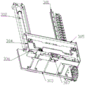
FIG. 1 is a schematic structural view of the present invention;
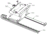
FIG. 2 is a schematic diagram of the structure of the present invention from another perspective;
FIG. 3 is a schematic structural diagram of a loading module;
FIG. 4 is a schematic structural view of the feeding module with the first screw frame removed;
FIG. 5 is a schematic structural diagram of a first storage bin for bearing workpieces;
fig. 6 is a schematic structural view of a loading robot;
FIG. 7 is a schematic structural diagram of a first cylinder module;
FIG. 8 is a schematic structural view of a second cylinder module;
FIG. 9 is a schematic structural view of a barrier assembly;
notation in the figure: 100 is a feeding module, 200 is a feeding manipulator, 300 is a first cylinder module, 400 is a transfer line, 500 is a second cylinder module, 600 is a blanking manipulator, 700 is a blanking module, 800 is a labeling machine, 301 is a first linear slide rail, 302 is a first rodless cylinder, 303 is a first rack, 304 is a first flow line, 305 is a first fixed side plate, 306 is a first positioning side plate, 307 is a first positioning cylinder, 501 is a second linear slide rail, 502 is a second rodless cylinder, 503 is a second rack, 504 is a second flow line, 505 is a second fixed side plate, 506 is a second positioning cylinder, 507 is a second positioning side plate, 101 is a first bin, 102 is a first lead screw, 103 is a first lifting bottom plate, 104 is a first slot, 201 is a first manipulator body, 202 is a first connecting rack, 203 is a first suction nozzle, 410 is a line mounting rack, 420 is a blocking assembly, 421 is a cylinder rack, 422 is a blocking cylinder, 423 is a blocking sheet, 1 is a first support table, 2 is a second support table, 3 is a carrier, and 4 is a workpiece.
Detailed Description
With reference to fig. 1 to 9, the automatic loading and unloading and carrier rotating mechanism for labeling machine includes a loading module 100, a loading manipulator 200, a first cylinder module 300, a transfer line 400, a second cylinder module 500, an unloading manipulator 600 and an unloading module 700, wherein the first cylinder module 300 and the second cylinder module 500 are disposed in parallel on two sides of the labeling machine 800 and the transfer line 400; the first cylinder module 300 comprises a first linear slide rail 301, a first rodless cylinder 302, a first rack 303 and a first flow line 304, the first linear slide rail 301 is fixedly arranged on the first supporting platform 1 positioned on one side of the feeding end of the labeling machine, a first linear slide block in sliding fit with the first linear slide rail 301 is arranged at the bottom of the first rack 303, the slide block of the first rodless cylinder 302 is fixedly connected with the bottom side of the first rack 303 to drive the first rack 303 to reciprocate along the first linear slide rail 301, and the first flow line 304 is arranged on the first rack 303 and the transmission direction of the first flow line is vertical to the reciprocating direction of the first rack 303; the second cylinder module 500 comprises a second linear slide rail 501, a second rodless cylinder 502, a second rack 503 and a second production line 504, the second linear slide rail 501 is fixedly arranged on the second support platform 2 positioned on one side of the discharging end of the labeling machine, a second linear slide block in sliding fit with the second linear slide rail 501 is arranged at the bottom of the second rack 503, the slide block of the second rodless cylinder 502 is fixedly connected with the bottom side of the second rack 503 to drive the second rack 503 to reciprocate along the second linear slide rail 501, and the second production line 504 is arranged on the second rack 503, and the transmission direction of the second production line is vertical to the reciprocating direction of the second rack 503; after the loading manipulator 200 adsorbs and conveys the workpiece 4 in the loading module 100 to the carrier 3 on the first flow line 304, the carrier 3 and the workpiece 4 are conveyed to the labeling machine flow line through the first flow line 304, and after the workpiece 4 is adhered by the labeling machine 800, the labeling machine flow line conveys the carrier 3 and the workpiece 4 to the second flow line 504, the unloading manipulator 600 adsorbs and moves the workpiece 4 on the carrier 3 on the second flow line 504 to the unloading module 700, and the carrier 3 on the second flow line 504 can move towards one end of the transfer line 400 after being driven by the second rodless cylinder 502, and rotates to the first flow line 304 through the transfer line 400, so that the carrier 3 can be reused.
The feeding manipulator 200 comprises a first manipulator body 201, a first connecting frame 202 which is fixed on the first manipulator body 201 and moves under the driving of the first manipulator body 201, and a plurality of first suction nozzles 203 which are fixed on the first connecting frame 202 and are arranged downwards for adsorbing the workpiece 4 to be labeled.
The discharging manipulator 600 comprises a second manipulator body, a second connecting frame which is fixed on the second manipulator body and moves under the drive of the second manipulator body, and a plurality of second suction nozzles which are fixed on the second connecting frame and are arranged downwards and used for adsorbing the labeled workpiece 4.
The transfer line 400 is fixed on the first supporting table 1 and the second supporting table 2 at both sides of the labeling machine 800 through the line mounting bracket 410, and at least one set of blocking assembly 420 located above the transfer line 400 and used for blocking the movement of the carrier 3 is further installed on the transfer line, the blocking assembly 420 comprises a cylinder bracket 421 erected on the frame body of the transfer line 400, a blocking cylinder 422 fixed on the cylinder bracket 421 and a blocking piece 423 fixedly connected with the movable end of the blocking cylinder 422, and the blocking piece 423 can block the movement of the carrier 3 located on the transfer line 400 by abutting against the transfer line 400 under the driving of the blocking cylinder 422.
One side of the first assembly line 304 is provided with a first fixed side plate 305 fixed on the first rack 303, the first rack 303 is further fixed with a first positioning cylinder 307, the movable end of the first positioning cylinder 307 is provided with a first positioning side plate 306 relatively matched with the first fixed side plate 305, and the carrier 3 moves between the first fixed side plate 305 and the first positioning side plate 306 along with the second assembly line 504.
A second fixed side plate 505 fixed on the second rack 503 is arranged on one side of the second assembly line 504, a second positioning cylinder 506 is further fixed on the second rack 503, a second positioning side plate 507 relatively matched with the second fixed side plate 505 is mounted at the movable end of the second positioning cylinder 506, and the carrier 3 moves between the second fixed side plate 505 and the second positioning side plate 507 along with the second assembly line 504.
The feeding module 100 comprises a first bin 101, a first lead screw 102 and a first lifting bottom plate 103, the first bin 101 is fixedly arranged in a first supporting platform 1, the top side of the first bin is open, a first slot 104 matched with the first lifting bottom plate 103 is formed in the bottom side of the first bin, the first lead screw is erected and fixed on a bin mounting seat on the first supporting platform through a first lead screw frame, one end, deviating from the first bin 101, of the first lifting bottom plate 103 is fixedly connected with a first sliding block arranged on the first lead screw 102, the first sliding block is in threaded connection with the first lead screw 102, the first lead screw 102 is driven to rotate through a motor shaft of a first motor, the first lifting bottom plate 103 is driven to lift workpieces 4 stacked in the first bin 101, the rotation of the first lead screw can be started, and the workpieces can be conveniently placed in and taken out.
The first line 304, the second line 504, and the transfer line 400 are belt line assemblies.
The working principle of the invention is as follows: the loading manipulator 200 sucks the workpiece 4 manually loaded into the first bin 101 through the first suction nozzle 203, drives the workpiece 4 to move, and conveys the workpiece 4 to the carrier 3 on the first flow line 304, then the first flow line 304 is started to move, so that the carrier 3 and the workpiece 4 placed on the first flow line 304 are conveyed to the self-contained work flow line of the labeling machine, and after being attached by the labeling machine 800, the labeling machine flow line conveys the carrier 3 and the workpiece 4 to the second flow line 504 abutted against the labeling machine from the discharge end of the labeling machine, then the unloading manipulator 600 sucks and moves the workpiece 4 on the carrier 3 of the second flow line 504 to the second bin of the unloading module 700, and simultaneously the carrier 3 on the second flow line 504 can move towards one end of the transfer flow line 400 after being driven by the second rodless cylinder 502 and rotate to the first flow line 304 through the transfer flow line 400, realize reuse of carrier 3, and because sustainable from material loading module 100 of material loading manipulator 200 material loading to first assembly line 304, can hold the gyration of a plurality of carriers 3 simultaneously on the transfer assembly line 400 promptly, when needs material loading is to first assembly line 304, first rodless cylinder 302 can promote first assembly line 304 fast and accept carrier 3 from transfer assembly line 400, then get back to original material loading position, accept the adsorbed work piece 4 of material loading manipulator 200, and then first assembly line 304 operates, make carrier 3 work piece 4 enter into labeller 800 together, consequently can realize the work piece 4 automatic feeding, when unloading, can realize carrier 3 cyclic use again, the gyration efficiency is higher simultaneously.
Although the present invention has been described in detail with reference to the foregoing embodiments, it will be apparent to those skilled in the art that changes may be made in the embodiments and/or equivalents thereof without departing from the spirit and scope of the invention. Any modification, equivalent replacement, or improvement made within the spirit and principle of the present invention should be included in the protection scope of the present invention.
Claims (9)
1. The automatic feeding and discharging and carrier slewing mechanism of the labeling machine is characterized by comprising a feeding module, a feeding manipulator, a first air cylinder module, a transfer assembly line, a second air cylinder module, a discharging manipulator and a discharging module, wherein the first air cylinder module and the second air cylinder module are distributed on two sides of the labeling machine and the transfer assembly line in parallel;
the first air cylinder module comprises a first linear slide rail, a first rodless air cylinder, a first rack and a first flow line, the first linear slide rail is fixedly arranged on a first supporting platform positioned on one side of the feeding end of the labeling machine, a first linear slide block in sliding fit with the first linear slide rail is arranged at the bottom of the first rack, the slide block of the first rodless air cylinder is fixedly connected with the bottom side of the first rack to drive the first rack to reciprocate along the first linear slide rail, the first flow line is arranged on the first rack, and the transmission direction of the first flow line is vertical to the reciprocating direction of the first rack;
the second cylinder module comprises a second linear slide rail, a second rodless cylinder, a second rack and a second assembly line, the second linear slide rail is fixedly arranged on a second support table positioned on one side of the discharging end of the labeling machine, a second linear slide block in sliding fit with the second linear slide rail is arranged at the bottom of the second rack, the slide block of the second rodless cylinder is fixedly connected with the bottom side of the second rack to drive the second rack to reciprocate along the second linear slide rail, and the second assembly line is arranged on the second rack and the transmission direction of the second assembly line is vertical to the reciprocating direction of the second rack;
the material loading manipulator adsorbs will work piece among the material loading module transports back on the carrier on the first assembly line, the carrier with the work piece warp on the labeller assembly line is carried to first assembly line, and through the labeller laminating back, follow the discharge end of labeller, the labeller assembly line transports carrier and work piece on the second assembly line, unloading manipulator will work piece adsorption on the second assembly line carrier moves to unloading module, just carrier on the second assembly line can be after the drive of second rodless cylinder, the orientation transfer assembly line one end moves, and through the transfer assembly line, turns round to on the first assembly line, realizes the reuse of carrier.
2. The automatic loading and unloading and carrier revolving mechanism for labeling machine of claim 1, wherein the loading manipulator comprises a first manipulator body, a first connecting frame fixed on the first manipulator body and driven by the first manipulator body to move, and a plurality of first suction nozzles fixed on the first connecting frame and arranged downward for sucking the workpiece to be labeled.
3. The automatic loading and unloading and carrier revolving mechanism of a labeling machine according to claim 1, wherein the loading robot comprises a second robot body, a second connecting frame fixed on the second robot body and driven by the second robot body, and a plurality of second suction nozzles fixed on the second connecting frame and arranged downward for sucking the labeled workpiece.
4. The automatic loading and unloading and carrier revolving mechanism of labeling machine according to claim 1, wherein the transfer line is fixed on the first supporting platform and the second supporting platform at both sides of the labeling machine through a line mounting bracket, and at least one set of blocking components for blocking the movement of the carrier is further installed on the transfer line, the blocking components comprise a cylinder bracket erected on the frame body of the transfer line, a blocking cylinder fixed on the cylinder bracket, and a blocking piece fixedly connected with the movable end of the blocking cylinder, and the blocking piece can be driven by the blocking cylinder to abut against the transfer line to block the movement of the carrier on the transfer line.
5. The automatic loading and unloading and carrier rotating mechanism of a labeling machine as claimed in claim 1, wherein a first fixed side plate fixed on the first rack is disposed at one side of the first assembly line, a first positioning cylinder is further fixed on the first rack, a first positioning side plate matching with the first fixed side plate is mounted at a movable end of the first positioning cylinder, and the carrier moves between the first fixed side plate and the first positioning side plate and along with the second assembly line.
6. The automatic loading and unloading and carrier rotating mechanism of a labeling machine as claimed in claim 1, wherein a second fixed side plate fixed on the second rack is disposed on one side of the second assembly line, a second positioning cylinder is further fixed on the second rack, a second positioning side plate matching with the second fixed side plate is mounted at a movable end of the second positioning cylinder, and the carrier moves between the second fixed side plate and the second positioning side plate and along with the second assembly line.
7. The automatic loading and unloading and carrier rotation mechanism of labeling machine of claim 1, wherein the loading module comprises a first bin, a first lead screw and a first lifting bottom plate, the first bin is fixedly disposed in the first supporting table, and has an opening on a top side thereof, a first slot matched with the first lifting bottom plate is disposed on a bottom side thereof, the first lead screw is fixedly mounted on a bin mounting seat on the first supporting table through a first lead screw frame, and one end of the first lifting bottom plate deviating from the first bin is fixedly connected with a first sliding block disposed on the first lead screw, and the first sliding block is in threaded connection with the first lead screw, the first lead screw is driven to rotate by a motor shaft of a first motor to drive the first lifting bottom plate to lift the workpieces stacked in the first bin.
8. The automatic loading and unloading and carrier swing mechanism of labeling machine of claim 1, wherein the unloading module comprises a second bin, a second lead screw and a second lifting bottom plate, the second bin is fixedly disposed in the second support platform, and has an opening on a top side thereof, a second slot is disposed on a bottom side thereof and is matched with the second lifting bottom plate, the second lead screw is mounted on a bin mounting seat fixed on the second support platform through a second lead screw frame, and one end of the second lifting bottom plate departing from the second bin is fixedly connected with a second sliding block disposed on the second lead screw, and the second sliding block is connected with the second lead screw through a screw thread, the second lead screw is driven to rotate by a motor shaft of a second motor to drive the second lifting bottom plate to descend and stack the workpieces in the second bin.
9. The automatic loading and unloading and carrier rotating mechanism of labeling machine as claimed in claim 1, wherein said first assembly line, said second assembly line and said transfer assembly line are belt assembly lines.
Priority Applications (1)
| Application Number | Priority Date | Filing Date | Title |
|---|---|---|---|
| CN201911301549.3A CN110817023A (en) | 2019-12-17 | 2019-12-17 | Automatic feeding and discharging and carrier rotating mechanism of labeling machine |
Applications Claiming Priority (1)
| Application Number | Priority Date | Filing Date | Title |
|---|---|---|---|
| CN201911301549.3A CN110817023A (en) | 2019-12-17 | 2019-12-17 | Automatic feeding and discharging and carrier rotating mechanism of labeling machine |
Publications (1)
| Publication Number | Publication Date |
|---|---|
| CN110817023A true CN110817023A (en) | 2020-02-21 |
Family
ID=69546052
Family Applications (1)
| Application Number | Title | Priority Date | Filing Date |
|---|---|---|---|
| CN201911301549.3A Pending CN110817023A (en) | 2019-12-17 | 2019-12-17 | Automatic feeding and discharging and carrier rotating mechanism of labeling machine |
Country Status (1)
| Country | Link |
|---|---|
| CN (1) | CN110817023A (en) |
Cited By (2)
| Publication number | Priority date | Publication date | Assignee | Title |
|---|---|---|---|---|
| CN113319218A (en) * | 2021-05-31 | 2021-08-31 | 江苏创源电子有限公司 | Bending assembly line |
| CN113578666A (en) * | 2021-08-05 | 2021-11-02 | 苏州迅益科系统科技有限公司 | Automatic assembling device and method for gasket |
Citations (7)
| Publication number | Priority date | Publication date | Assignee | Title |
|---|---|---|---|---|
| US20050034423A1 (en) * | 2003-07-02 | 2005-02-17 | Siegmar Sindermann | Beverage bottling plant for filling bottles with a liquid beverage filling material having a container filling plant container information adding station, such as, a labeling station, configured to add information to containers, such as, bottles and cans, and modules for labeling stations and a bottling plant having a mobile module carrier |
| CN205952510U (en) * | 2016-07-29 | 2017-02-15 | 东莞华懋精密机械科技有限公司 | Automatic sticking film machine of 4S |
| CN107933063A (en) * | 2017-12-30 | 2018-04-20 | 苏州富强科技有限公司 | Workpiece patch automatic stripper |
| WO2018094680A1 (en) * | 2016-11-25 | 2018-05-31 | 苏州富强科技有限公司 | Full-automatic feeding production line |
| CN108275332A (en) * | 2018-01-24 | 2018-07-13 | 九仕恒自动化科技(昆山)有限公司 | A kind of modularization automatic laminating machine |
| CN108584051A (en) * | 2018-06-05 | 2018-09-28 | 李占胜 | Intelligent labelling machine |
| CN211167733U (en) * | 2019-12-17 | 2020-08-04 | 苏州迅益科系统科技有限公司 | Automatic feeding and discharging and carrier rotating mechanism of labeling machine |
-
2019
- 2019-12-17 CN CN201911301549.3A patent/CN110817023A/en active Pending
Patent Citations (7)
| Publication number | Priority date | Publication date | Assignee | Title |
|---|---|---|---|---|
| US20050034423A1 (en) * | 2003-07-02 | 2005-02-17 | Siegmar Sindermann | Beverage bottling plant for filling bottles with a liquid beverage filling material having a container filling plant container information adding station, such as, a labeling station, configured to add information to containers, such as, bottles and cans, and modules for labeling stations and a bottling plant having a mobile module carrier |
| CN205952510U (en) * | 2016-07-29 | 2017-02-15 | 东莞华懋精密机械科技有限公司 | Automatic sticking film machine of 4S |
| WO2018094680A1 (en) * | 2016-11-25 | 2018-05-31 | 苏州富强科技有限公司 | Full-automatic feeding production line |
| CN107933063A (en) * | 2017-12-30 | 2018-04-20 | 苏州富强科技有限公司 | Workpiece patch automatic stripper |
| CN108275332A (en) * | 2018-01-24 | 2018-07-13 | 九仕恒自动化科技(昆山)有限公司 | A kind of modularization automatic laminating machine |
| CN108584051A (en) * | 2018-06-05 | 2018-09-28 | 李占胜 | Intelligent labelling machine |
| CN211167733U (en) * | 2019-12-17 | 2020-08-04 | 苏州迅益科系统科技有限公司 | Automatic feeding and discharging and carrier rotating mechanism of labeling machine |
Cited By (3)
| Publication number | Priority date | Publication date | Assignee | Title |
|---|---|---|---|---|
| CN113319218A (en) * | 2021-05-31 | 2021-08-31 | 江苏创源电子有限公司 | Bending assembly line |
| CN113578666A (en) * | 2021-08-05 | 2021-11-02 | 苏州迅益科系统科技有限公司 | Automatic assembling device and method for gasket |
| CN113578666B (en) * | 2021-08-05 | 2023-02-03 | 苏州迅益科系统科技有限公司 | Automatic assembling device and method for gasket |
Similar Documents
| Publication | Publication Date | Title |
|---|---|---|
| CN109264359B (en) | Touch screen feeding equipment | |
| JP3792996B2 (en) | Die and small parts transfer device | |
| CN110817023A (en) | Automatic feeding and discharging and carrier rotating mechanism of labeling machine | |
| CN112466797A (en) | Chip assembly feeding and discharging machine | |
| CN211282797U (en) | New forms of energy battery piece assembly mechanism | |
| CN211167733U (en) | Automatic feeding and discharging and carrier rotating mechanism of labeling machine | |
| CN113044288A (en) | Go up unloading integral type pad pasting device | |
| CN109994574B (en) | Battery string member feeding device and feeding method | |
| CN201952003U (en) | Magazine circulation device and system thereof | |
| CN111891608A (en) | Feeding and discharging mechanism for layered materials | |
| JPH11222317A (en) | Plate transfering device | |
| CN111908122A (en) | Automatic production device for photovoltaic solar frame | |
| CN111604689A (en) | Automatic assembling machine | |
| CN214526830U (en) | Trigger of putting that can be used to flexible line way board | |
| CN109809184B (en) | Feeding and discharging device | |
| CN209804696U (en) | Laminating machine and battery piece scribing and gluing device thereof | |
| CN111015240A (en) | Full-automatic processing assembly line | |
| CN214705859U (en) | Semi-automatic semiconductor chip production and installation equipment | |
| CN220664111U (en) | Automatic feeding device of electronic device | |
| CN220811097U (en) | Pendulum material equipment | |
| CN111628387B (en) | Card holds in palm bullet spare assembly system | |
| CN217577188U (en) | Feeding structure for cleaning machine | |
| CN220449084U (en) | Full-automatic blanking machine of FPC magnetism carrier | |
| CN219597375U (en) | Detection device | |
| CN115332123B (en) | Wafer water glue laminating machine |
Legal Events
| Date | Code | Title | Description |
|---|---|---|---|
| PB01 | Publication | ||
| PB01 | Publication | ||
| SE01 | Entry into force of request for substantive examination | ||
| SE01 | Entry into force of request for substantive examination |