CN110802661A - Cotton equipment of piece formula pearl cuts - Google Patents
Cotton equipment of piece formula pearl cuts Download PDFInfo
- Publication number
- CN110802661A CN110802661A CN201911248288.3A CN201911248288A CN110802661A CN 110802661 A CN110802661 A CN 110802661A CN 201911248288 A CN201911248288 A CN 201911248288A CN 110802661 A CN110802661 A CN 110802661A
- Authority
- CN
- China
- Prior art keywords
- cutting
- plate
- wall
- movably
- pearl
- Prior art date
- Legal status (The legal status is an assumption and is not a legal conclusion. Google has not performed a legal analysis and makes no representation as to the accuracy of the status listed.)
- Pending
Links
Images

Classifications
-
- B—PERFORMING OPERATIONS; TRANSPORTING
- B26—HAND CUTTING TOOLS; CUTTING; SEVERING
- B26D—CUTTING; DETAILS COMMON TO MACHINES FOR PERFORATING, PUNCHING, CUTTING-OUT, STAMPING-OUT OR SEVERING
- B26D1/00—Cutting through work characterised by the nature or movement of the cutting member or particular materials not otherwise provided for; Apparatus or machines therefor; Cutting members therefor
- B26D1/01—Cutting through work characterised by the nature or movement of the cutting member or particular materials not otherwise provided for; Apparatus or machines therefor; Cutting members therefor involving a cutting member which does not travel with the work
- B26D1/547—Cutting through work characterised by the nature or movement of the cutting member or particular materials not otherwise provided for; Apparatus or machines therefor; Cutting members therefor involving a cutting member which does not travel with the work having a wire-like cutting member
- B26D1/553—Cutting through work characterised by the nature or movement of the cutting member or particular materials not otherwise provided for; Apparatus or machines therefor; Cutting members therefor involving a cutting member which does not travel with the work having a wire-like cutting member with a plurality of wire-like cutting members
-
- B—PERFORMING OPERATIONS; TRANSPORTING
- B26—HAND CUTTING TOOLS; CUTTING; SEVERING
- B26D—CUTTING; DETAILS COMMON TO MACHINES FOR PERFORATING, PUNCHING, CUTTING-OUT, STAMPING-OUT OR SEVERING
- B26D7/00—Details of apparatus for cutting, cutting-out, stamping-out, punching, perforating, or severing by means other than cutting
- B26D7/01—Means for holding or positioning work
- B26D7/02—Means for holding or positioning work with clamping means
- B26D7/025—Means for holding or positioning work with clamping means acting upon planar surfaces
-
- B—PERFORMING OPERATIONS; TRANSPORTING
- B26—HAND CUTTING TOOLS; CUTTING; SEVERING
- B26D—CUTTING; DETAILS COMMON TO MACHINES FOR PERFORATING, PUNCHING, CUTTING-OUT, STAMPING-OUT OR SEVERING
- B26D7/00—Details of apparatus for cutting, cutting-out, stamping-out, punching, perforating, or severing by means other than cutting
- B26D7/08—Means for treating work or cutting member to facilitate cutting
- B26D7/14—Means for treating work or cutting member to facilitate cutting by tensioning the work
-
- B—PERFORMING OPERATIONS; TRANSPORTING
- B26—HAND CUTTING TOOLS; CUTTING; SEVERING
- B26D—CUTTING; DETAILS COMMON TO MACHINES FOR PERFORATING, PUNCHING, CUTTING-OUT, STAMPING-OUT OR SEVERING
- B26D7/00—Details of apparatus for cutting, cutting-out, stamping-out, punching, perforating, or severing by means other than cutting
- B26D7/26—Means for mounting or adjusting the cutting member; Means for adjusting the stroke of the cutting member
- B26D7/2628—Means for adjusting the position of the cutting member
Abstract
The invention relates to the technical field of pearl wool processing, and discloses a piece-cutting type pearl wool processing device. This equipment that piece formula pearl is cotton cuts, including cutting main frame, feeding mechanism, receiving mechanism, feeding mechanism is installed in the left side of cutting main frame, receiving mechanism is installed on the right side of cutting main frame, the cutting main frame includes the bottom plate, the equal fixed mounting in both ends has the curb plate about bottom plate top outer wall. This equipment that cuts piece formula pearl is cotton through the setting of cutting conveyer belt, slider, cross-cut line, makes the cutting conveyer belt drive the cross-cut line and removes, carries out the cross-cut to the pearl cotton, through the setting of transfer line, driving motor, drive mechanism, transmission connecting rod, and driving motor drives perpendicular tangent line and reciprocates, carries out vertical cutting to the pearl cotton. The second rocker arm is rotated forwards and backwards to drive the adjusting plate to move left and right, so that the pearl cotton can be adjusted conveniently according to the size of the pearl cotton.
Description
Technical Field
The invention relates to the technical field of pearl wool processing, in particular to a piece-cutting type pearl wool processing device.
Background
The pearl cotton, namely the polyethylene foam cotton, is a non-crosslinked closed-cell structure and is a novel environment-friendly packaging material. It is made up by using low-density polyethylene resin through the process of physical foaming process to produce countless independent bubbles. Overcomes the defects of easy breakage, deformation and poor restorability of common foaming glue. The material has the advantages of water resistance, moisture resistance, shock resistance, sound insulation, heat preservation, good plasticity, strong toughness, cyclic reconstruction, environmental protection, strong impact resistance and the like, and also has good chemical resistance. Is an ideal substitute of the traditional packaging material. The packaging bag is widely applied to packaging of various products such as automobile cushions, throw pillows, electronic appliances, instruments and meters, computers, sound equipment, medical appliances, industrial control cabinets, hardware lamp decorations, artware, glass, ceramics, household appliances, spraying, furniture and furniture, and the like, and express packaging.
When pearl cotton is processed, the pearl cotton needs to be cut, but in the prior art, the pearl cotton is usually cut manually by measuring and cutting, and the manual cutting consumes manpower and has low efficiency. Therefore, the device for cutting the flake-type pearl cotton is provided.
Disclosure of Invention
Aiming at the defects of the prior art, the invention provides equipment for cutting flake type pearl cotton, which has the advantages of automatic cutting, high efficiency and the like, and solves the problem that the existing cutting of the pearl cotton is usually measured manually. The labor consumption and the efficiency are low.
The technical scheme adopted by the invention for solving the technical problems is as follows: the utility model provides an equipment that piece formula pearl is cotton cuts, includes cutting main frame, feeding mechanism, receiving mechanism, feeding mechanism is installed in the left side of cutting main frame, receiving mechanism is installed on the right side of cutting main frame.
The cutting main frame comprises a bottom plate, side plates are fixedly arranged at the left end and the right end of the outer wall of the top of the bottom plate, a top plate is fixedly arranged between the side plates and positioned right above the bottom plate, a rotating shaft is movably arranged above the top plate, two upper bevel gears are fixedly arranged on the outer wall of the rotating shaft, a lower bevel gear is movably arranged below each upper bevel gear, a vertical screw is fixedly connected to the bottom end of each lower bevel gear, a thread block is engaged and connected to the outer wall of each vertical screw, an upper conveying roller is movably arranged between the thread blocks, a support plate is fixedly arranged below the vertical screw, two bases are fixedly arranged on the outer wall of the top of the support plate, a lower conveying roller is movably arranged between the bases, a conveying motor is fixedly arranged on the outer wall of the back of the support plate, and a connecting plate is fixedly arranged below, the cutting conveying belt is arranged on the outer wall of the front side of the connecting plate, the connecting block is arranged on the cutting conveying belt, the sliding block is movably arranged on the outer wall of the bottom of the top plate, a transverse cutting line is fixedly arranged between the sliding block and the connecting block, side sliding rails are fixedly arranged on the outer walls of the inner sides of the two side plates, a sliding plate is movably connected inside each side sliding rail, two supporting rods are fixedly arranged between the two sliding plates, a plurality of cutting blocks are movably arranged on the outer wall of each supporting rod, vertical cutting lines are fixedly connected between the corresponding upper and lower cutting blocks, an adjusting plate is movably arranged on the right side of each cutting block, a transverse screw is movably arranged above each supporting rod, a second rocker arm is fixedly connected to the right end of each transverse screw, a plurality of supporting blocks are fixedly arranged on the outer wall of the top of, the left end transmission of transfer line is connected with drive mechanism, the drive mechanism left side is connected with the transmission connecting rod.
The feeding mechanism comprises a feeding support, and a feeding conveyor belt is arranged on the feeding support.
The receiving mechanism comprises a receiving support, and a receiving conveyor belt is arranged on the receiving support.
Furthermore, the rotating shaft penetrates through the side plate on the right side and is movably connected with the side plate, the right end of the rotating shaft is fixedly connected with a first rocker arm, and the left end of the rotating shaft is provided with a bearing.
Furthermore, be provided with two bearings on the top outer wall of roof, lower bevel gear and bearing swing joint, and every lower bevel gear all is connected with the last bevel gear meshing that corresponds.
Further, the base is movably connected with one end, far away from the lower bevel gear, of the vertical lead screw, and the conveying motor is in transmission connection with the lower conveying roller through a belt.
Furthermore, a motor is arranged on the outer wall of one side of the back of the thread block, the motor is in transmission connection with the upper conveying roller through a belt, and the rotation direction of the motor is opposite to that of the conveying motor.
Furthermore, a sliding groove is formed in the outer wall of the bottom of the top plate, and the sliding block is movably connected with the sliding groove.
Furthermore, the support rod penetrates through the adjusting plate and is movably connected with the adjusting plate, and the cross screw penetrates through the adjusting plate and is connected with the adjusting plate in a meshed mode.
Furthermore, the driving motor is in transmission connection with the transmission rod through a belt, and the transmission connecting rod is fixedly connected with the sliding plate.
The invention has the beneficial effects that:
1. this equipment that cuts piece formula pearl is cotton through the setting of cutting conveyer belt, slider, cross-cut line, makes the cutting conveyer belt drive the cross-cut line and removes, carries out the cross-cut to the pearl cotton, through the setting of transfer line, driving motor, drive mechanism, transmission connecting rod, and driving motor drives perpendicular tangent line and reciprocates, carries out vertical cutting to the pearl cotton. The adjusting plate can be driven to move left and right by forward and backward rotation of the second rocker arm, so that the pearl cotton can be adjusted according to the size of the pearl cotton, the pearl cotton can be automatically cut, the manual use is reduced, and the working efficiency is improved.
2. This cotton equipment of cutting piece formula pearl, clockwise rotation first rocking arm through last bevel gear and lower bevel gear's setting, can drive perpendicular thick stick and rotate, makes the screw thread piece downstream to carry the cylinder downstream in the drive, make upper and lower cylinder press from both sides tight pearl cotton, under the drive of motor, upper and lower cylinder roll and drive the cotton tight removal that is tightening of pearl, thereby make the cotton cutting of being convenient for of pearl, improved the practicality.
Drawings
In order to more clearly illustrate the embodiments of the present invention or the technical solutions in the prior art, the drawings used in the description of the embodiments or the prior art will be briefly described below.
FIG. 1 is a schematic structural view of the present invention;
FIG. 2 is a left side view of the cutter body of the present invention;
FIG. 3 is a right side view of the present invention at the support plate;
fig. 4 is a schematic view of the overall structure of the present invention.
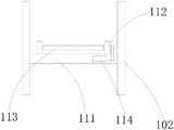
Description of reference numerals: 1 cutting main frame, 101 bottom plate, 102 side plate, 103 top plate, 104 rotating shaft, 105 first rocker arm, 106 upper bevel gear, 107 lower bevel gear, 108 vertical screw rod, 109 thread block, 110 upper conveying roller, 111 supporting plate, 112 base, 113 lower conveying roller, 114 conveying motor, 115 connecting plate, 116 cutting conveyor belt, 117 connecting block, 118 slider, 119 transverse tangent line, 120 side slide rail, 121 sliding plate, 122 supporting rod, 123 tangent line block, 124 vertical tangent line, 125 adjusting plate, 126 transverse screw rod, 127 second rocker arm, 128 supporting block, 129 transmission rod, 130 driving motor, 131 transmission mechanism, 132 transmission connecting rod, 2 feeding mechanism, 201 feeding bracket, 202 feeding conveyor belt, 3 receiving mechanism, 301 receiving bracket and 302 receiving conveyor belt.
Detailed Description
The technical solution in the embodiments of the present invention will be clearly and completely described below with reference to the accompanying drawings in the embodiments of the present invention.
Referring to fig. 1-4, an apparatus for cutting flake pearl wool includes a cutting main frame 1, a feeding mechanism 2, and a receiving mechanism 3, wherein the feeding mechanism 2 is installed on the left side of the cutting main frame 1, and the receiving mechanism 3 is installed on the right side of the cutting main frame 1.
The cutting main frame 1 comprises a bottom plate 101, side plates 102 are fixedly arranged at the left end and the right end of the outer wall of the top of the bottom plate 101, a top plate 103 is fixedly arranged between the side plates 102 and positioned right above the bottom plate 101, a rotating shaft 104 is movably arranged above the top plate 103, the rotating shaft 104 penetrates through the side plate 102 on the right side and is movably connected with the side plate, a first rocker arm 105 is fixedly connected with the right end of the rotating shaft 104, a bearing is arranged at the left end of the rotating shaft 104, two upper bevel gears 106 are fixedly arranged on the outer wall of the rotating shaft 104, a lower bevel gear 107 is movably arranged below each upper bevel gear 106, two bearings are arranged on the outer wall of the top plate 103, the lower bevel gear 107 is movably connected with the bearing, each lower bevel gear 107 is meshed with the corresponding upper bevel gear 106, a vertical screw 108 is fixedly connected with the bottom end of each lower, an upper conveying roller 110 is movably arranged between the thread blocks 109, a supporting plate 111 is fixedly arranged below the vertical screw rod 108, two bases 112 are fixedly arranged on the outer wall of the top of the supporting plate 111, a lower conveying roller 113 is movably arranged between the bases 112, a conveying motor 114 is fixedly arranged on the outer wall of one side of the back of the supporting plate 111, the bases 112 are movably connected with one end, far away from the lower bevel gear 107, of the vertical screw rod 108, the conveying motor 114 is in transmission connection with the lower conveying roller 113 through a belt, a motor is arranged on the outer wall of one side of the back of the thread blocks 109 and is in transmission connection with the upper conveying roller 110 through a belt, the rotating direction of the motor is opposite to that of the conveying motor 114, a connecting plate 115 is fixedly arranged below the supporting plate 111, a cutting conveying belt 116 is arranged on the outer wall of the front side of the connecting plate 115, a, the outer wall of the bottom of the top plate 103 is provided with a chute, a slide block 118 is movably connected with the chute, a transverse tangent line 119 is fixedly installed between the slide block 118 and the connecting block 117, the outer walls of the inner sides of the two side plates 102 are fixedly provided with side slide rails 120, the inside of each side slide rail 120 is movably connected with a slide plate 121, two support rods 122 are fixedly installed between the two slide plates 121, the outer wall of each support rod 122 is movably provided with a plurality of tangent blocks 123, vertical tangent lines 124 are fixedly connected between the corresponding upper tangent blocks 123 and the lower tangent blocks, the right side of each tangent block 123 is movably provided with an adjusting plate 125, a transverse lead screw 126 is movably installed above each support rod 122, each support rod 122 penetrates through each adjusting plate 125 and is movably connected with the support plate, each transverse lead screw 126 penetrates through each adjusting plate 125 and is meshed with the corresponding adjusting plate, the right end, a transmission rod 129 is movably arranged in the supporting block 128, a driving motor 130 is arranged on one side of the back of the transmission rod 129, the left end of the transmission rod 129 is in transmission connection with a transmission mechanism 131, the left side of the transmission mechanism 131 is connected with a transmission connecting rod 132, the driving motor 130 is in transmission connection with the transmission rod 129 through a belt, and the transmission connecting rod 132 is fixedly connected with the sliding plate 121. Both the transverse cut line 119 and the vertical cut line 124 are diamond cut lines.
The feeding mechanism 2 comprises a feeding support 201, and a feeding conveyor belt 202 is arranged on the feeding support 201.
The receiving mechanism 3 comprises a receiving support 301, and a receiving conveyor belt 302 is arranged on the receiving support 301.
When the pearl cotton cutting machine is used, the first rocker arm 105 is rotated clockwise, the vertical screw rod 108 can be driven to rotate through the arrangement of the upper bevel gear 106 and the lower bevel gear 107, the thread block 109 is driven to move downwards, the upper conveying roller 110 is driven to move downwards, the pearl cotton is clamped by the upper roller and the lower roller, and the pearl cotton is driven by the motor to move tightly through rolling of the upper roller and the lower roller, so that the pearl cotton is convenient to cut. The pearl cotton is sent between the upper conveying roller 110 and the lower conveying roller 113 by the feeding conveyor belt 202, and the cut pearl cotton falls on the feeding conveyor belt 302. The cutting conveyor belt 116 drives the transverse cutting line 119 to move left and right to cut the pearl cotton transversely, and the driving motor 130 drives the vertical cutting line 124 to move up and down to cut the pearl cotton vertically. The second rocker arm 127 is rotated forwards and backwards to drive the adjusting plate 125 to move left and right, so that the pearl cotton can be adjusted conveniently according to the size of the pearl cotton.
The previous description of the disclosed embodiments is provided to enable any person skilled in the art to make or use the present invention. Various modifications to these embodiments will be readily apparent to those skilled in the art, and the generic principles defined herein may be applied to other embodiments without departing from the spirit or scope of the invention. Thus, the present invention is not intended to be limited to the embodiments shown herein but is to be accorded the widest scope consistent with the principles and novel features disclosed herein.
Claims (8)
1. The utility model provides a cut cotton equipment of piece formula pearl, includes cutting main frame (1), feeding mechanism (2), receiving mechanism (3), its characterized in that: a feeding mechanism (2) is installed on the left side of the cutting main rack (1), and a receiving mechanism (3) is installed on the right side of the cutting main rack (1);
the cutting main frame (1) comprises a bottom plate (101), side plates (102) are fixedly mounted at the left end and the right end of the outer wall of the top of the bottom plate (101), a top plate (103) is fixedly mounted between the side plates (102) and located right above the bottom plate (101), a rotating shaft (104) is movably mounted above the top plate (103), two upper bevel gears (106) are fixedly mounted on the outer wall of the rotating shaft (104), a lower bevel gear (107) is movably mounted below each upper bevel gear (106), a vertical lead screw (108) is fixedly connected to the bottom end of each lower bevel gear (107), a thread block (109) is meshed with the outer wall of each vertical lead screw (108), an upper conveying roller (110) is movably mounted between the thread blocks (109), a support plate (111) is fixedly mounted below the vertical lead screw (108), and two bases (112) are fixedly mounted on the outer wall of the top of the support plate (111), the cutting and conveying device is characterized in that a lower conveying roller (113) is movably arranged between the bases (112), a conveying motor (114) is fixedly arranged on the outer wall of one side of the back of the supporting plate (111), a connecting plate (115) is fixedly arranged below the supporting plate (111), a cutting and conveying belt (116) is arranged on the outer wall of the front side of the connecting plate (115), a connecting block (117) is arranged on the cutting and conveying belt (116), a sliding block (118) is movably arranged on the outer wall of the bottom of the top plate (103), a transverse cutting line (119) is fixedly arranged between the sliding block (118) and the connecting block (117), side sliding rails (120) are fixedly arranged on the outer walls of the inner sides of the two side plates (102), a sliding plate (121) is movably connected inside each side sliding rail (120), two supporting rods (122) are fixedly arranged between the two sliding plates (121), and a plurality, a vertical cutting line (124) is fixedly connected between the upper and lower corresponding cutting line blocks (123), an adjusting plate (125) is movably mounted on the right side of each cutting line block (123), a transverse screw (126) is movably mounted above each supporting rod (122), a second rocker arm (127) is fixedly connected to the right end of each transverse screw (126), a plurality of supporting blocks (128) are fixedly mounted on the outer wall of the top of the bottom plate (101), a transmission rod (129) is movably mounted inside each supporting block (128), a driving motor (130) is mounted on one side of the back of each transmission rod (129), a transmission mechanism (131) is in transmission connection with the left end of each transmission rod (129), and a transmission connecting rod (132) is connected to the left side of each transmission mechanism (;
the feeding mechanism (2) comprises a feeding support (201), and a feeding conveyor belt (202) is arranged on the feeding support (201);
the material receiving mechanism (3) comprises a material receiving support (301), and a material receiving conveying belt (302) is arranged on the material receiving support (301).
2. The device for cutting flake type pearl wool according to claim 1, wherein: the rotating shaft (104) penetrates through the side plate (102) on the right side and is movably connected with the side plate, the right end of the rotating shaft (104) is fixedly connected with a first rocker arm (105), and the left end of the rotating shaft (104) is provided with a bearing.
3. The device for cutting flake type pearl wool according to claim 1, wherein: two bearings are arranged on the outer wall of the top plate (103), the lower bevel gears (107) are movably connected with the bearings, and each lower bevel gear (107) is meshed with the corresponding upper bevel gear (106).
4. The device for cutting flake type pearl wool according to claim 1, wherein: the base (112) is movably connected with one end, far away from the lower bevel gear (107), of the vertical screw rod (108), and the conveying motor (114) is in transmission connection with the lower conveying roller (113) through a belt.
5. The device for cutting flake type pearl wool according to claim 1, wherein: the outer wall of one side of the back of the thread block (109) is provided with a motor, the motor is in transmission connection with the upper conveying roller (110) through a belt, and the rotation direction of the motor is opposite to that of the conveying motor (114).
6. The device for cutting flake type pearl wool according to claim 1, wherein: the outer wall of the bottom of the top plate (103) is provided with a sliding groove, and the sliding block (118) is movably connected with the sliding groove.
7. The device for cutting flake type pearl wool according to claim 1, wherein: the supporting rod (122) penetrates through the adjusting plate (125) and is movably connected with the adjusting plate, and the transverse lead screw (126) penetrates through the adjusting plate (125) and is meshed with the adjusting plate.
8. The device for cutting flake type pearl wool according to claim 1, wherein: the driving motor (130) is in transmission connection with a transmission rod (129) through a belt, and the transmission connecting rod (132) is fixedly connected with the sliding plate (121).
Priority Applications (1)
| Application Number | Priority Date | Filing Date | Title |
|---|---|---|---|
| CN201911248288.3A CN110802661A (en) | 2019-12-09 | 2019-12-09 | Cotton equipment of piece formula pearl cuts |
Applications Claiming Priority (1)
| Application Number | Priority Date | Filing Date | Title |
|---|---|---|---|
| CN201911248288.3A CN110802661A (en) | 2019-12-09 | 2019-12-09 | Cotton equipment of piece formula pearl cuts |
Publications (1)
| Publication Number | Publication Date |
|---|---|
| CN110802661A true CN110802661A (en) | 2020-02-18 |
Family
ID=69492750
Family Applications (1)
| Application Number | Title | Priority Date | Filing Date |
|---|---|---|---|
| CN201911248288.3A Pending CN110802661A (en) | 2019-12-09 | 2019-12-09 | Cotton equipment of piece formula pearl cuts |
Country Status (1)
| Country | Link |
|---|---|
| CN (1) | CN110802661A (en) |
Cited By (3)
| Publication number | Priority date | Publication date | Assignee | Title |
|---|---|---|---|---|
| CN111546387A (en) * | 2020-06-30 | 2020-08-18 | 张�浩 | Anti-static pearl wool roll forming, conveying and slitting process |
| CN113368780A (en) * | 2021-06-29 | 2021-09-10 | 安徽方信立华环保科技有限公司 | Denitrification agent wet blank rotary cutter |
| CN113427559A (en) * | 2021-07-02 | 2021-09-24 | 西安交通大学医学院第二附属医院 | Nano fetuin test paper for monitoring diabetic retinopathy and preparation process thereof |
-
2019
- 2019-12-09 CN CN201911248288.3A patent/CN110802661A/en active Pending
Cited By (5)
| Publication number | Priority date | Publication date | Assignee | Title |
|---|---|---|---|---|
| CN111546387A (en) * | 2020-06-30 | 2020-08-18 | 张�浩 | Anti-static pearl wool roll forming, conveying and slitting process |
| CN111546387B (en) * | 2020-06-30 | 2021-11-26 | 陕西双夏包装材料有限公司 | Anti-static pearl wool roll forming, conveying and slitting process |
| CN113368780A (en) * | 2021-06-29 | 2021-09-10 | 安徽方信立华环保科技有限公司 | Denitrification agent wet blank rotary cutter |
| CN113427559A (en) * | 2021-07-02 | 2021-09-24 | 西安交通大学医学院第二附属医院 | Nano fetuin test paper for monitoring diabetic retinopathy and preparation process thereof |
| CN113427559B (en) * | 2021-07-02 | 2023-03-10 | 西安交通大学医学院第二附属医院 | Nano fetuin test paper for monitoring diabetic retinopathy and preparation process thereof |
Similar Documents
| Publication | Publication Date | Title |
|---|---|---|
| CN110802661A (en) | Cotton equipment of piece formula pearl cuts | |
| CN202805268U (en) | Multistation cutting device for phenolic foam board | |
| CN211250205U (en) | Cotton equipment of piece formula pearl cuts | |
| CN213138225U (en) | Air blowing and dust removing device of pad printing machine for producing electric saw plastic handle | |
| CN204249195U (en) | Novel sponge production and processing device | |
| CN218019751U (en) | Limiting and conveying device for overall foaming of refrigerator shell of display cabinet | |
| CN109434916B (en) | Slicing device convenient for adjusting slicing thickness for agricultural product processing | |
| CN215591746U (en) | Curb plate width adjusting device is used in sponge production | |
| CN203401300U (en) | Cylindrical metal tube automatic multifunctional continuous machining line integrated equipment | |
| CN111251357B (en) | Trimmer is used in processing of plastic-aluminum board convenient to multi-direction operation of adjusting | |
| CN213107139U (en) | Reliable full-automatic sponge cutting machine | |
| CN209049784U (en) | One kind having cleaning function side plate conveying device | |
| CN209905774U (en) | Automatic meat meal conveying device | |
| CN220952681U (en) | Sterile type plane ear-hanging type medical mask cutting device | |
| CN216372367U (en) | Multifunctional vegetable cutter for food production | |
| CN220030415U (en) | Adjustable pearl cotton slitting machine | |
| CN219648964U (en) | Numerical control synchronous cutting device | |
| CN218694317U (en) | Plate shearing positioning mechanism for machining refrigerator rail accessories | |
| CN218504636U (en) | Automatic cutting machine for rubber and plastic heat-insulation board | |
| CN219056699U (en) | Conveying device for wet tissues packaging | |
| CN204248953U (en) | Sponge transporting and cutting apparatus | |
| CN220503517U (en) | Cloth cutter with regulatory function | |
| CN219054488U (en) | Cutting machine for napkin paper production | |
| CN215422521U (en) | Domestic instant noodle mold | |
| CN113524740B (en) | Production device for heat-conducting gasket with high heat conductivity coefficient |
Legal Events
| Date | Code | Title | Description |
|---|---|---|---|
| PB01 | Publication | ||
| PB01 | Publication | ||
| SE01 | Entry into force of request for substantive examination | ||
| SE01 | Entry into force of request for substantive examination |