CN110774657A - Environment-friendly paper lunch box trimming equipment - Google Patents
Environment-friendly paper lunch box trimming equipment Download PDFInfo
- Publication number
- CN110774657A CN110774657A CN201911194963.9A CN201911194963A CN110774657A CN 110774657 A CN110774657 A CN 110774657A CN 201911194963 A CN201911194963 A CN 201911194963A CN 110774657 A CN110774657 A CN 110774657A
- Authority
- CN
- China
- Prior art keywords
- box
- trimming
- adsorption
- die
- machine tool
- Prior art date
- Legal status (The legal status is an assumption and is not a legal conclusion. Google has not performed a legal analysis and makes no representation as to the accuracy of the status listed.)
- Pending
Links
Images


Classifications
-
- B—PERFORMING OPERATIONS; TRANSPORTING
- B31—MAKING ARTICLES OF PAPER, CARDBOARD OR MATERIAL WORKED IN A MANNER ANALOGOUS TO PAPER; WORKING PAPER, CARDBOARD OR MATERIAL WORKED IN A MANNER ANALOGOUS TO PAPER
- B31B—MAKING CONTAINERS OF PAPER, CARDBOARD OR MATERIAL WORKED IN A MANNER ANALOGOUS TO PAPER
- B31B50/00—Making rigid or semi-rigid containers, e.g. boxes or cartons
- B31B50/14—Cutting, e.g. perforating, punching, slitting or trimming
- B31B50/142—Cutting, e.g. perforating, punching, slitting or trimming using presses or dies
-
- B—PERFORMING OPERATIONS; TRANSPORTING
- B31—MAKING ARTICLES OF PAPER, CARDBOARD OR MATERIAL WORKED IN A MANNER ANALOGOUS TO PAPER; WORKING PAPER, CARDBOARD OR MATERIAL WORKED IN A MANNER ANALOGOUS TO PAPER
- B31B—MAKING CONTAINERS OF PAPER, CARDBOARD OR MATERIAL WORKED IN A MANNER ANALOGOUS TO PAPER
- B31B50/00—Making rigid or semi-rigid containers, e.g. boxes or cartons
- B31B50/02—Feeding or positioning sheets, blanks or webs
- B31B50/04—Feeding sheets or blanks
- B31B50/07—Feeding sheets or blanks by air pressure or suction
-
- B—PERFORMING OPERATIONS; TRANSPORTING
- B31—MAKING ARTICLES OF PAPER, CARDBOARD OR MATERIAL WORKED IN A MANNER ANALOGOUS TO PAPER; WORKING PAPER, CARDBOARD OR MATERIAL WORKED IN A MANNER ANALOGOUS TO PAPER
- B31B—MAKING CONTAINERS OF PAPER, CARDBOARD OR MATERIAL WORKED IN A MANNER ANALOGOUS TO PAPER
- B31B50/00—Making rigid or semi-rigid containers, e.g. boxes or cartons
- B31B50/14—Cutting, e.g. perforating, punching, slitting or trimming
- B31B50/20—Cutting sheets or blanks
-
- B—PERFORMING OPERATIONS; TRANSPORTING
- B31—MAKING ARTICLES OF PAPER, CARDBOARD OR MATERIAL WORKED IN A MANNER ANALOGOUS TO PAPER; WORKING PAPER, CARDBOARD OR MATERIAL WORKED IN A MANNER ANALOGOUS TO PAPER
- B31B—MAKING CONTAINERS OF PAPER, CARDBOARD OR MATERIAL WORKED IN A MANNER ANALOGOUS TO PAPER
- B31B50/00—Making rigid or semi-rigid containers, e.g. boxes or cartons
- B31B50/74—Auxiliary operations
Abstract
An environment-friendly paper lunch box edge cutting device comprises a punching mechanism, an edge material collecting box and a transferring mechanism. The punching mechanism comprises a machine tool, a punching plate, a positioning lower die, a trimming upper die and a driving piece, the machine tool is provided with a workbench, the trimming upper die is arranged towards the positioning lower die, the positioning lower die and the trimming upper die are both communicated with an air pump, the transfer mechanism comprises a transmission belt, a displacement component, a turnover component, an adsorption manipulator and a push plate, the displacement component is arranged on the transmission belt, the turnover component is used for driving the adsorption manipulator to rotate, the displacement component is used for driving the adsorption manipulator to reciprocate between the transmission belt and the machine tool, the positioning lower die and the trimming upper die can adsorb a meal box, the meal box is adsorbed and positioned by the positioning lower die during trimming, and the meal box is lifted away by the trimming upper die during die opening, so that the action steps; when the adsorption manipulator stretches into the machine tool, the push plate sweeps across the lower positioning die and pushes the rim charge into the rim charge collecting box in a centralized manner.
Description
Technical Field
The invention relates to the field of paper tableware production, in particular to an environment-friendly paper lunch box edge cutting device.
Background
In recent years, the take-out industry is rapidly developed in China, more and more people select to use APP for taking out, and with the rise of the take-out industry, the use of disposable lunch boxes for containing food is also rising, wherein the paper lunch boxes have the advantages of low manufacturing cost, easy recovery, low environmental pollution and the like, so the market demand for the paper lunch boxes is increasing. The preparation of the paper lunch box comprises the procedures of preparing paper pulp, dehydrating and forming, hot-pressing and shaping, trimming, sterilizing and the like.
The paper cutlery box shape has been basically fixed after processes such as dehydration shaping, hot pressing design, and remaining has the rim charge on the border position of paper cutlery box this moment, in order to guarantee the uniformity of cutlery box size to and be convenient for pack it and go out the goods, need carry out the rim charge excision operation to the paper cutlery box of accomplishing the setting, the side cut process is gone on side cut equipment.
It can be understood that after carrying out the excision operation to the cutlery box, the rim charge that is excised can remain near equipment location portion, before carrying out the side cut operation again, need wash the side cut equipment, whether the remaining rim charge on the equipment of person can influence normal side cut process, hinders the cutlery box and normally puts into the location portion of side cut equipment.
Generally, before the lunch box is placed into the edge cutting equipment, an air gun is needed to blow air to the positioning part of the edge cutting equipment, and the leftover materials remained in the positioning part are blown away by high-pressure air, namely before the movement of cutting the leftover materials every time, the operation of blowing air is needed to be carried out.
However, when the rim charge is cleared away through the high-pressure gas, the trend of the rim charge is difficult to control, the blown-away rim charge cannot be normally recovered, and the rim charge cutting operation is discontinuous due to the existence of the blowing process, so that the shaping efficiency of the edge of the lunch box is influenced, therefore, how to improve the equipment structure, the problem of difficulty in clearing the rim charge is solved, the production efficiency of the paper lunch box is improved, and the manufacturing quality of the paper lunch box is improved.
Disclosure of Invention
The invention aims to overcome the defects in the prior art and provides the edge cutting equipment for the environment-friendly paper lunch box, wherein the discharging position of the equipment is arranged on the side surface of a machine tool, a part for clearing the rim charge is arranged on a material taking mechanism, the lunch box is lifted by the edge cutting part after the edge cutting operation of the lunch box is completed, the lunch box is far away from the rim charge, the material taking mechanism enters the machine tool to take the lunch box and pushes away the rim charge, the clearing operation and the material taking operation of the rim charge are combined together, the total consumption of the rim charge cutting process is shortened, and the edge cutting efficiency is improved.
The purpose of the invention is realized by the following technical scheme:
an environmental protection paper cutlery box side cut equipment includes: the stamping mechanism, the rim charge collecting box and the transferring mechanism are arranged on the frame;
the punching mechanism comprises a machine tool, a punching plate, a positioning lower die, an upper trimming die and a driving piece, the machine tool is provided with a workbench, the positioning lower die is arranged on the workbench, the punching plate is arranged on the machine tool in a sliding mode and is positioned right above the workbench, the upper trimming die is arranged on the punching plate and is arranged towards the positioning lower die, the positioning lower die and the upper trimming die are communicated with an air pump, and the driving piece is arranged on the machine tool and is used for driving the upper trimming die to reciprocate towards a direction close to or far away from the positioning lower die;
the scrap collecting box is arranged on one side of the machine tool;
the transfer mechanism includes transmission band, displacement subassembly, upset subassembly, adsorption apparatus hand and push pedal, the transmission band set up in the lathe is kept away from one side of rim charge collecting box, just the transmission band with be provided with the interval between the lathe, the displacement subassembly set up in on the transmission band, the upset unit mount in on the displacement subassembly, adsorption apparatus hand set up in on the upset subassembly, the upset subassembly is used for the drive adsorption apparatus hand is rotatory, the displacement subassembly is used for the drive adsorption apparatus hand in the transmission band with reciprocal displacement between the lathe, the push pedal set up in on the pusher apparatus hand is close to lathe one side, the push pedal is used for promoting the rim charge to being close to the direction removal of rim charge collecting box.
In one embodiment, the adsorption manipulator comprises a support frame and a plurality of adsorption discs, the support frame is mounted on the turnover component, the adsorption discs are arranged on the support frame at intervals, each adsorption disc is used for adsorbing a paper lunch box, and the push plate is mounted on the side face, far away from the turnover component, of the support frame.
In one embodiment, the push plate comprises a fastening piece and a scraping piece, the fastening piece is mounted on the supporting frame, the scraping piece is arranged on the fastening piece, and the direction of the scraping piece is opposite to that of the adsorption disc.
In one embodiment, the driving member is a cylinder.
In one embodiment, the driving member is provided in plurality.
In one embodiment, the rim charge collecting box comprises a box body, a bearing frame and a plurality of casters, the casters are mounted at the bottom of the bearing frame, the box body is arranged in the bearing frame, and a feeding port is formed in the top of the box body.
In one embodiment, a material guiding bevel edge is arranged at the edge position of the material inlet.
In one embodiment, a movable door is arranged on the side surface of the box body.
In one embodiment, the carrying frame is provided with a handrail.
In one embodiment, the displacement assembly comprises a foot rest, a transverse translation electric cylinder and a longitudinal displacement electric cylinder, the foot rest is arranged on the conveying belt, the transverse translation electric cylinder is mounted on the foot rest, the longitudinal displacement electric cylinder is arranged on the transverse translation electric cylinder, the transverse translation electric cylinder is used for driving the longitudinal displacement electric cylinder to be close to or far away from the machine tool, the overturning assembly is arranged on the longitudinal displacement electric cylinder, and the longitudinal displacement electric cylinder is used for driving the overturning assembly to be close to or far away from the conveying belt.
Compared with the prior art, the invention has at least the following advantages:
1. the positioning lower die and the trimming upper die are both communicated with the air pump, so that the positioning lower die and the trimming upper die can adsorb a lunch box, the lunch box is adsorbed and positioned by the positioning lower die during trimming, and the lunch box is lifted away by the trimming upper die during die opening, thereby saving the action steps of a manipulator and separating the lunch box from cut scraps;
2. set up the push pedal on the adsorption apparatus hand, when the adsorption apparatus hand stretched into the lathe, the push pedal was swept and is fixed a position the lower mould, in concentrating the rim charge and pushing into the rim charge collecting box, the realization will be got the integration of material step and rim charge washing step.
3. Clear away the rim charge through the push pedal, the centralized processing rim charge of being convenient for avoids polluting equipment all ring edge borders, and the clearance is convenient, reduces operating personnel working strength.
Drawings
In order to more clearly illustrate the technical solutions of the embodiments of the present invention, the drawings needed to be used in the embodiments will be briefly described below, it should be understood that the following drawings only illustrate some embodiments of the present invention and therefore should not be considered as limiting the scope, and for those skilled in the art, other related drawings can be obtained according to the drawings without inventive efforts.
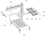
FIG. 1 is a schematic view of an edge trimming apparatus for an environment-friendly paper meal box according to an embodiment of the present invention;
FIG. 2 is a schematic view of the edge cutting apparatus for the environmentally friendly paper meal box shown in FIG. 1;
FIG. 3 is a schematic structural view of the trimming device for the environmentally friendly paper meal box when the material is taken by the transferring mechanism;
FIG. 4 is a schematic structural diagram of a transfer mechanism according to an embodiment of the present invention;
FIG. 5 is an exploded view of the positioning drag and trimming cope mold in accordance with an embodiment of the present invention;
fig. 6 is a schematic structural view of the positioning lower die and the trimming upper die in a die-closed state.
Detailed Description
To facilitate an understanding of the invention, the invention will now be described more fully with reference to the accompanying drawings. Preferred embodiments of the present invention are shown in the drawings. This invention may, however, be embodied in many different forms and should not be construed as limited to the embodiments set forth herein. Rather, these embodiments are provided so that this disclosure will be thorough and complete.
It will be understood that when an element is referred to as being "secured to" another element, it can be directly on the other element or intervening elements may also be present. When an element is referred to as being "connected" to another element, it can be directly connected to the other element or intervening elements may also be present. The terms "vertical," "horizontal," "left," "right," and the like as used herein are for illustrative purposes only and do not represent the only embodiments.
Unless defined otherwise, all technical and scientific terms used herein have the same meaning as commonly understood by one of ordinary skill in the art to which this invention belongs. The terminology used herein in the description of the invention is for the purpose of describing particular embodiments only and is not intended to be limiting of the invention. As used herein, the term "and/or" includes any and all combinations of one or more of the associated listed items.
Referring to fig. 1, an apparatus 10 for trimming an environmentally friendly paper meal box includes: the stamping mechanism 100, the rim charge collecting box 200 and the transferring mechanism 300. The rim charge collecting box 200 and the transfer mechanism 300 are respectively arranged on the stamping mechanism 100, a part for clearing rim charges is arranged on the transfer mechanism 300 to replace the existing blowing cleaning structure, the lunch box is lifted by the stamping mechanism 100 after the trimming operation is finished on the lunch box, so that the lunch box is far away from the rim charges, the transfer mechanism 300 enters a machine tool to push the rim charges into the rim charge collecting box 200 while taking the lunch box, the clearing operation and the taking operation of the rim charges are combined together, the total consumption of the rim charge cutting process is shortened, and the trimming efficiency is improved.
Referring to fig. 1 and 2, the punching mechanism 100 includes a machine tool 110, a punching plate 120, a positioning lower die 130, a trimming upper die 140 and a driving member 150, the machine tool 110 is provided with a worktable 111, the positioning lower die 130 is arranged on the worktable 111, the punching plate 120 is slidably arranged on the machine tool 110, the punching plate 120 is located right above the worktable 111, the trimming upper die 140 is mounted on the punching plate 120, the trimming upper die 140 is arranged towards the positioning lower die 130, the positioning lower die 130 and the trimming upper die 140 are both communicated with an air pump, and the driving member 150 is arranged on the machine tool 110 and is used for driving the trimming upper die 140 to reciprocate towards or away from the positioning lower die 130. The positioning lower die 130 is used for positioning the lunch box, and the trimming upper die 140 is used for cutting off the rim charge of the lunch box.
The punching mechanism 100 is used for trimming the lunch box, and comprises the following specific steps: in an initial state (as shown in fig. 1), the punch plate 120 is far away from the workbench 111, at this time, the trimming upper die 140 is located right above the positioning lower die 130, and a gap exists between the trimming upper die 140 and the positioning lower die 130, that is, a material taking interval;
the lunch box conveying mechanism transfers the lunch box to be trimmed to the position of the positioning lower die 130, the air pump is started at the moment, negative pressure is generated on the positioning lower die 130 to adsorb the lunch box, the lunch box is fixed at the position of the positioning lower die 130, and the lunch box is positioned at the moment;
the driving member 150 is started to push the punch plate 120 to descend, so that the trimming upper die 140 is attached to the positioning lower die 130, and the rim charge on the lunch box is cut off, and at this time, the matching state of the trimming upper die 140 and the positioning lower die 130 is shown in fig. 6;
then, the positioning lower die 130 stops adsorbing the lunch box, the trimming upper die 140 generates negative pressure to adsorb the lunch box, the driving member 150 is started again to pull the punching plate 120 to rise, the trimming upper die 140 is driven by the punching plate 120 to be away from the positioning lower die 130, the lunch box with the cut rim charge is lifted by the trimming upper die 140 at the moment, the cut rim charge is retained on the positioning lower die 130, and the cutting step of the rim charge is completed.
The scrap collecting box 200 is provided at one side of the machine tool 110, and the scrap collecting box 200 is used to store the cut scrap.
Referring to fig. 1 and 4, the transfer mechanism 300 includes a transmission belt 310, a displacement assembly 320, an overturning assembly 330, an adsorbing manipulator 340 and a push plate 350, the transmission belt 310 is disposed on one side of the machine tool 110 far away from the rim charge collecting box 200, a space is disposed between the transmission belt 310 and the machine tool 110, the displacement assembly 320 is disposed on the transmission belt 310, the overturning assembly 330 is mounted on the displacement assembly 320, the adsorbing manipulator 340 is disposed on the overturning assembly 330, the overturning assembly 330 is used for driving the adsorbing manipulator 340 to rotate, the displacement assembly 320 is used for driving the adsorbing manipulator 340 to reciprocate between the transmission belt 310 and the machine tool 110, the push plate 350 is disposed on one side of the material pushing manipulator near the machine tool 110, and the push plate 350 is used for pushing the rim charge.
Cutlery box accomplishes rim charge excision operation back in punching press mechanism 100 departments, shifts by transfer mechanism 300, transports the cutlery box of accomplishing the rim charge excision to disinfection station department through transfer mechanism 300 and disinfects, wherein, concrete action is as follows when shifting the cutlery box:
referring to fig. 1, in an initial state, the adsorption manipulator 340 is located right above the conveyor belt 310, and the adsorption part of the adsorption manipulator 340 is disposed toward the conveyor belt 310, that is, the adsorption part of the adsorption manipulator 340 faces downward;
when the material taking step is started, the overturning component 330 drives the adsorption manipulator 340 to overturn for 180 degrees, so that the adsorption part of the adsorption manipulator 340 is arranged upwards;
it should be noted that after the trimming step, the lunch box with trimmed edges is lifted by the trimming upper die 140 and suspended over the positioning lower die 130, at this time, the trimming upper die 140 is separated from the positioning lower die 130 to form a material taking region again,
the displacement assembly 320 pushes the adsorption manipulator 340 to extend into the material taking section, at this time, the adsorption manipulator 340 is located between the positioning lower die 130 and the positioning lower die 130, the adsorption part of the adsorption manipulator 340 faces the meal box on the edge cutting upper die 140, after the displacement assembly 320 moves the adsorption manipulator 340 upwards to make the adsorption part adhere to the outer wall of the meal box, the adsorption manipulator 340 is started to generate a suction force to adsorb the meal box, at this time, the edge cutting upper die 140 stops adsorbing the meal box, the adsorption manipulator 340 takes down the meal box, and at this time, the matching state of the adsorption manipulator 340 and the punching mechanism 100 is shown in fig. 4;
it should be noted that, when the displacement assembly 320 pushes the adsorption manipulator 340 to extend into the material taking section, the push plate 350 disposed on the adsorption manipulator 340 may enter the material taking section together, and the push plate 350 contacts with the outer wall of the positioning lower mold 130, and in the process of extending the manipulator 340, the side close to the transmission belt 310 by the positioning lower mold 130 is swept to the side close to the rim charge collecting box 200 by the positioning lower mold 130, so that the rim charge staying on the surface of the positioning lower mold 130 is swept into the rim charge collecting box 200.
After the meal box is taken off by the adsorption manipulator 340, the displacement assembly 320 is started again, the adsorption manipulator 340 is dragged out from the material taking interval, at the moment, the adsorption manipulator 340 is moved right above the transmission band 310, the overturning assembly 330 drives the adsorption manipulator 340 to rotate 180 degrees again, and the meal box on the adsorption manipulator 340 faces the transmission band 310.
The shifting unit 320 descends to make the lunch box on the adsorption robot 340 fit with the transmission band 310, and then the lunch box is placed on the surface of the transmission band 310, and then the shifting unit 320 drives the adsorption robot 340 to ascend and move to the initial position, and the transmission band 310 starts to transfer the lunch box to the next station.
Through going up mould 140 and air pump intercommunication on will fixing a position lower mould 130 and the side cut for mould 140 all possesses the ability of adsorbing the cutlery box on fixing a position lower mould 130 and the side cut, makes mould 140 can take out the cutlery box along the area after accomplishing the rim charge excision action to the cutlery box on the side cut, makes the cutlery box can separate with the rim charge, so that follow-up transfer mechanism 300 gets the material in step and the operation of clearing up.
The edge material collecting box 200 is swept into the edge material through the push plate 350, so that the edge material is conveniently subjected to centralized processing, the follow-up cleaning of operators is not needed, the labor intensity of operators is reduced, and the automation degree of the equipment is improved.
Referring to fig. 4, in order to improve the adsorption capacity of the adsorption robot 340 to the lunch box and reduce the weight of the adsorption robot 340 to reduce the burden of the displacement assembly 320, thereby reducing the occurrence rate of equipment failure, the adsorption robot 340 includes a support frame 341 and a plurality of adsorption trays 342, the support frame 341 is installed on the turnover assembly 330, the plurality of adsorption trays 342 are arranged on the support frame 341 at intervals, each adsorption tray 342 is used for adsorbing a paper lunch box, and the push plate 350 is installed on the side of the support frame 341 away from the turnover assembly 330. Wherein, the support frame 341 is built by many aluminium alloy, reduces the whole quality of absorption manipulator 340 through support frame 341, and a plurality of absorption dish 342 are adsorbed the cutlery box. Thus, the load applied to the displacement assembly 320 and the turnover assembly 330 is reduced, the inertia force generated by the movement of the suction robot 340 is reduced, and the abrasion amount of the parts on the displacement assembly 320 and the turnover assembly 330 is reduced, thereby reducing the occurrence rate of equipment failure.
Referring to fig. 4, in an embodiment, in order to facilitate maintenance of the adsorption manipulator 340, the adsorption manipulator 340 further includes a plurality of adjustment sheets 343 disposed on the supporting frame 341 at intervals, and each adjustment sheet has a distance adjustment slot on a side thereof away from the supporting frame 341, and a plurality of adsorption trays 342 are correspondingly inserted through the distance adjustment slots one by one.
Referring to fig. 4, in an embodiment, in order to improve the ability of the push plate 350 to sweep the rim charge, improve the service life of the push plate 350, and avoid the vibration generated to the adsorption manipulator 340 when the push plate 350 sweeps the rim charge, the push plate 350 includes a fastening plate 351 and a scraping plate 352, the fastening plate 351 is installed on the supporting frame 341, the scraping plate 352 is disposed on the fastening plate 351, and the orientations of the scraping plate 352 and the adsorption tray 342 are opposite. The fastening piece 351 is used for connecting the scraping piece 352 to the adsorption manipulator 340, the scraping piece 352 is used for sweeping off the edge materials, the push plate 350 is arranged in a segmented mode, the scraping piece 352 can be replaced independently when being excessively worn, different materials can be adopted for the fastening piece 351 and the scraping piece 352, the buffer capacity between the fastening piece 351 and the scraping piece 352 is improved, for example, the scraping piece 352 is replaced by soft rubber, the elasticity of the scraping piece 352 is increased, and the situation that vibration generated when the scraping piece 352 sweeps on the positioning lower die 130 is directly transmitted to the adsorption manipulator 340 is avoided.
Referring to fig. 1, in order to increase the trimming pressure, the driving member 150 is a cylinder, and a plurality of driving members 150 are provided.
Referring to fig. 2, in order to facilitate the processing of the rim charge, the rim charge collecting box 200 includes a box body 210, a carrying frame 220 and a plurality of casters 230, the casters 230 are mounted at the bottom of the carrying frame 220, the box body 210 is disposed in the carrying frame 220, a feeding port 211 is disposed at the top of the box body 210, a material guiding bevel 240 is disposed at the edge of the feeding port 211, a movable door 250 is disposed on the side surface of the box body 210, and a handrail 260 is disposed on the carrying frame 220. Increase the area of boundary material collecting box 200 through guide hypotenuse 240, guarantee that the boundary material that push pedal 350 swept out can pass the pan feeding mouth 211 smoothly and fall into box 210 in, can promote to bear frame 220 through handrail 260 and move to the position of unloading, and open box 210 and go up dodge gate 250 and can directly sweep out the boundary material in the box 210, need not overturn box 210 and also lift the boundary material off, reduce operator's intensity of labour.
Referring to fig. 2, in an embodiment, the displacement assembly 320 includes a foot rest 321, a horizontal translation electric cylinder 322, and a vertical translation electric cylinder 323, the foot rest 321 is disposed on the conveyor belt 310, the horizontal translation electric cylinder 322 is mounted on the foot rest 321, the vertical translation electric cylinder 323 is disposed on the horizontal translation electric cylinder 322, the horizontal translation electric cylinder 322 is used for driving the vertical translation electric cylinder 323 to approach or leave the machine tool 110, the turning assembly 330 is disposed on the vertical translation electric cylinder 323, and the vertical translation electric cylinder 323 is used for driving the turning assembly 330 to approach or leave the conveyor belt 310.
Compared with the prior art, the invention has at least the following advantages:
1. the positioning lower die 130 and the trimming upper die 140 are both communicated with the air pump, so that the positioning lower die 130 and the trimming upper die 140 can adsorb a lunch box, the lunch box is adsorbed and positioned by the positioning lower die 130 during trimming, and the lunch box is lifted by the trimming upper die 140 during die opening, thereby saving the action steps of a manipulator and separating the lunch box from cut scraps;
2. the push plate 350 is arranged on the adsorption manipulator 340, when the adsorption manipulator 340 extends into the machine tool 110, the push plate 350 sweeps the lower positioning die 130, the rim charge is pushed into the rim charge collecting box 200 in a centralized manner, and the integration of the material taking step and the rim charge cleaning step is realized.
3. Clear away the rim charge through push pedal 350, the centralized processing rim charge of being convenient for avoids polluting equipment all ring edge borders, and the clearance is convenient, reduces operating personnel working strength.
It can be understood that in order to improve side cut efficiency, there are a plurality of cutlery boxes to carry out the rim charge excision work simultaneously on the side cut equipment generally, and before the rim charge on the excision cutlery box, need exert the fixed force with the cutlery box of putting into the mould, make it keep motionless in the mould, in order to avoid haring the cutlery box, generally adopt the fixed cutlery box of the mode of adsorbing the cutlery box. However, because there are a plurality of cutlery boxes that need to continue to adsorb, negative pressure chamber is seted up at every cutlery box location position department on the mould, and every negative pressure chamber all communicates with the air pump, bleeds through the air pump and forms the negative pressure and then adsorb the cutlery box, owing to need connect the trachea to every negative pressure chamber, leads to the trachea wiring difficulty on the bead cutter, and because trachea is in large quantity, the later stage is maintained the degree of difficulty great. In addition, the size of cutlery box can change according to different customers' demand, and the cutlery box size of cutting edge and going on cutting edge promptly can be different, needs to replace the mould this moment, and because trachea quantity is many on the mould, erects again, put through the trachea and need occupy a large amount of time, and need have experienced maintainer to operate, and the degree of difficulty of replacement mould is big.
Therefore, how to optimize the structure of the existing trimming upper die 140 and reduce the operation difficulty when replacing the die is a problem to be solved by those skilled in the art.
In order to enable the trimming device 10 to replace the positioning lower mold 130 and the trimming upper mold 140 to meet the use requirements of different sizes of paper meal boxes,
referring to fig. 5 and 6, the lower positioning die 130 includes a backing plate 131, a bottom plate 132 and a positioning seat 133, the bottom plate 132 is mounted on the backing plate 131, the bottom plate 132 is provided with a plurality of air holes 132a, a flow guide net groove 132b and a plurality of negative pressure chambers 132c, the plurality of negative pressure chambers 132c are all located on a side surface of the bottom plate 132 away from the backing plate 131, the plurality of negative pressure chambers 132c are all communicated with the flow guide net groove 132b, the air holes 132a are communicated with one of the negative pressure chambers 132c, the positioning seat 133 is covered on the bottom plate 132, the positioning seat 133 is provided with a plurality of positioning cavities 133a, each positioning cavity 133a is used for accommodating one lunch box, the plurality of positioning cavities 133a are communicated with the plurality of negative pressure chambers 132c one by one, and the air holes 132a are communicated with an air pump;
referring to fig. 5 and 6, the trimming upper die 140 includes a connecting plate 141, a middle pad 142 and a plurality of trimming male dies 143, the middle pad 142 is mounted on the connecting plate 141, the middle pad 142 is provided with a plurality of through holes 142a and negative pressure holes 142b, a conduction groove 142c is respectively disposed between every two adjacent through holes 142a, the negative pressure holes 142b are communicated with one of the through holes 142a, the conduction groove 142c is located on a side surface of the middle pad 142 close to the connecting plate 141, the plurality of trimming male dies 143 cover the plurality of through holes 142a in a one-to-one correspondence manner, the plurality of trimming male dies 143 are disposed toward the plurality of positioning cavities 133a in a one-to-one correspondence manner, and the trimming male dies 143 are used for cutting off rim charge of the lunch box.
The trimming upper die 140 and the positioning lower die 130 are described in order to better understand the improved concept of the trimming upper die 140 and the positioning lower die 130.
Referring to fig. 5 and 6, the positioning lower mold 130 includes a backing plate 131, a bottom plate 132 and a positioning seat 133, the bottom plate 132 is mounted on the backing plate 131, the bottom plate 132 is provided with air holes 132a, a flow guiding net groove 132b and a plurality of negative pressure chambers 132c, the plurality of negative pressure chambers 132c are all located on a side surface of the bottom plate 132 away from the backing plate 131, the plurality of negative pressure chambers 132c are all communicated with the flow guiding net groove 132b, the air holes 132a are communicated with one of the negative pressure chambers 132c, the air holes 132a are used for being connected with an external air pump, each negative pressure chamber is used for forming a negative pressure area to adsorb a meal box, the flow guiding net groove 132b connects the plurality of negative pressure chambers 132c together, so that air is independently extracted from the air holes 132a to generate negative pressure in all the negative pressure chambers 132c, the number of air pipes is reduced, wiring of equipment is facilitated, and the number of parts to, the switching difficulty is low, the switching can be completed through simple operation indication, and professional assembly knowledge is not needed.
The positioning seat 133 covers the bottom plate 132, and the positioning seat 133 is provided with a plurality of positioning cavities 133a, each positioning cavity 133a is used for accommodating a lunch box, the plurality of positioning cavities 133a are communicated with the plurality of negative pressure chambers 132c in a one-to-one correspondence manner, and the air holes 132a are communicated with the air pump.
The positioning cavity 133a is used for accommodating a lunch box, the inner wall of the positioning cavity 133a is attached to the lunch box to position the lunch box, and when the device is started, the air pump pumps air in the bottom plate 132 through the air holes 132a, so that the negative pressure chambers 132c generate negative pressure to adsorb the lunch box in the positioning cavity 133 a.
Referring to fig. 5 and 6, the trimming upper die 140 includes a connecting plate 141, a middle pad 142 and a plurality of trimming male dies 143, the middle pad 142 is mounted on the connecting plate 141, the middle pad 142 is provided with a plurality of through holes 142a and negative pressure holes 142b, a conduction groove 142c is respectively disposed between every two adjacent through holes 142a, the negative pressure holes 142b are communicated with one of the through holes 142a, the conduction groove 142c is located on a side surface of the middle pad 142 close to the connecting plate 141, the plurality of trimming male dies 143 are covered with the plurality of through holes 142a in a one-to-one correspondence, the plurality of trimming male dies 143 are disposed toward the plurality of positioning cavities 133a in a one-to-one correspondence, and the trimming male dies 143 are used for cutting off rim charge of.
The through holes 142a are connected through the conduction groove 142c and are communicated with the air pump through the negative pressure hole 142b, the air pump is started to draw air in the middle cushion plate 142 through the negative pressure hole 142b, and negative pressure is generated at each through hole 142a so that the trimming male die 143 generates suction to adsorb the lunch boxes. The lunch box can be lifted from the positioning die 100, so that the follow-up material taking operation is convenient. Therefore, when the function that the trimming upper die 140 lifts up the lunch box is ensured, the purpose of reducing the number of the air pipes arranged on the trimming upper die 140 is reduced, the difficulty of switching the jig is reduced, and the maintenance difficulty is correspondingly reduced.
The trimming upper die 140 is arranged right above the positioning die 100, is positioned right below one trimming male die 143 after the lunch box is placed into the positioning cavity 131, and is driven by the trimming machine to descend the connecting plate 141 to drive the trimming male die 143 to press downwards, so that the trimming male die 143 cuts off the rim charge on the lunch box when contacting with the edge of the lunch box.
Further, in order to increase the trimming portion of the lunch box, the negative pressure chambers 132c are distributed in a rectangular array.
Referring to fig. 5 and fig. 6, in an embodiment, the positioning lower die 130 further includes a gasket 134, and the gasket 134 is disposed on a side surface of the positioning seat 133 away from the bottom plate 132.
Referring to fig. 5, in order to facilitate connection, a quick-change connector 132d is disposed on an outer wall of the bottom plate 132, and the quick-change connector 132d is communicated with the ventilation hole 132 a.
Referring to fig. 5, in order to reduce the difficulty of opening the die and prevent the trimming upper die 140 from being separated from the positioning lower die 130 due to negative pressure after trimming, the trimming upper die 140 further includes a die opening cylinder 144, the die opening cylinder 144 is mounted on the middle cushion plate 142, and an output end of the die opening cylinder 144 faces the positioning seat 133. And a plurality of mold opening cylinders 144 are provided. Thrust is applied between the trimming upper die 140 and the positioning lower die 130 by the unclamp cylinder 144 to assist the unclamp operation.
Referring to fig. 5 and 6, in order to facilitate trimming and sucking up the lunch box after trimming, the trimming punch 143 includes a profile positioning cover 143a and an annular blade 143b, the profile positioning cover 143a is covered on the through hole 142a, and the annular blade 143b is disposed on the outer wall of the profile positioning cover 143 a. The trimming male die 143 further comprises a hoop 143c, the hoop is sleeved on the outer wall of the profiling positioning cover 143a, and the annular blade 143b is positioned between the inner wall of the hoop 143c and the outer wall of the profiling positioning cover 143 a. The profiling positioning cover 143a and the annular blade 143b are separately arranged, the annular blade 143b is a wearing part, and when the annular blade 143b is worn, the hoop 143c can be opened to replace the annular blade 143 b.
In order to increase the adsorption force on the lunch box, the profiling positioning cover 143a is provided with a plurality of adsorption holes.
In order to replace the mold, the outer wall of the middle cushion plate 142 is provided with an alignment groove.
It can be understood that, in the positioning lower die 130, each negative pressure chamber 132c is communicated through the flow guiding mesh groove 132b, the air in each negative pressure chamber 132c is pumped by the air pump to generate negative pressure to further exert the adsorption force on the lunch box, and the output power of the air pump is increased along with the increase of the number of the negative pressure chambers 132c, so that the requirement on the air pump is high, the service life of the air pump is greatly shortened when the air pump is in a high-load operation state for a long time, in order to reduce the load of the air pump, the flow guiding mesh groove 132b is composed of a plurality of single channels, each single channel comprises a transverse channel and a longitudinal channel, the transverse channel and the longitudinal channel are intersected to form an X-shaped structure, the central positions of the transverse channel and the longitudinal channel are overlapped and communicated to form an intersection node, and two ends of the transverse channel and the longitudinal channel are communicated with one negative pressure chamber 132c, that is, each single channel, and a flow deflector is arranged at the position of the intersection node.
The negative pressure chambers 132c are connected in a connection mode that the transverse channels and the longitudinal channels are intersected, the distance between each negative pressure chamber 132c and the air holes 132a is further reduced, the hollow space in the bottom plate 132 is reduced, and the amount of air to be pumped by the air pump when negative pressure is formed in each negative pressure chamber 132c is further reduced, so that the output power of the air pump is reduced.
Further, in the gas extraction process, the flow direction of air in transverse channel and longitudinal channel is different, consequently can form the convection current when it meets in intersection node position department, lead to intersection node position department to produce the mixed flow, increase the degree of difficulty that gas was taken out, negative pressure chamber 132c sets up the volume more, its influence degree is big more, and can prevent through setting up the water conservancy diversion piece in intersection node position department that transverse channel and longitudinal channel department from flowing into the air and directly intersecting and form the convection current, utilize the air to contact with the water conservancy diversion piece behind the entering intersection node, and take place slightly turning to under the water conservancy diversion piece effect, the phenomenon that transverse channel and longitudinal channel take place direct hedging and lead to the mixed flow has been avoided, dredge the air flow direction in intersection node position department from this, reduce the air pump load of bleeding.
Compared with the prior art, the invention has at least the following advantages:
1. when the die is replaced, only the bottom plate 132, the positioning seat 133, the middle cushion plate 142 and the plurality of trimming male dies 143 on the trimming upper die 140 in the positioning lower die 130, namely the connecting plate 141 and the cushion plate 131 are used as common parts, so that the replacement parts are reduced, and the labor intensity of operators is relieved;
2. the negative pressure chambers 132c are communicated with each other through the flow guide net groove 132b, the air pump and the negative pressure chambers 132c are communicated through the air holes 132a, negative pressure adsorption lunch boxes can be formed in the negative pressure chambers 132c only by wiring the air holes 132a, and when a mould is replaced, air pipes at the positions of the air holes 132a are connected again, so that the difficulty in replacing the mould is reduced;
3. through reducing trachea use quantity, reduce the easy wearing and tearing part on the mould, and then reduce the fault rate of mould, reduce the maintenance degree of difficulty of mould.
The above-mentioned embodiments only express several embodiments of the present invention, and the description thereof is more specific and detailed, but not construed as limiting the scope of the invention. It should be noted that, for a person skilled in the art, several variations and modifications can be made without departing from the inventive concept, which falls within the scope of the present invention. Therefore, the protection scope of the present patent shall be subject to the appended claims.
Claims (10)
1. The utility model provides an environmental protection paper cutlery box side cut equipment which characterized in that includes:
the punching mechanism comprises a machine tool, a punching plate, a positioning lower die, an upper trimming die and a driving piece, the machine tool is provided with a workbench, the positioning lower die is arranged on the workbench, the punching plate is arranged on the machine tool in a sliding mode and is positioned right above the workbench, the upper trimming die is arranged on the punching plate and is arranged towards the positioning lower die, the positioning lower die and the upper trimming die are communicated with an air pump, and the driving piece is arranged on the machine tool and is used for driving the upper trimming die to reciprocate towards a direction close to or far away from the positioning lower die;
the rim charge collecting box is arranged on one side of the machine tool;
transfer mechanism, transfer mechanism includes transmission band, displacement subassembly, upset subassembly, adsorption apparatus hand and push pedal, the transmission band set up in the lathe is kept away from one side of rim charge collecting box, just the transmission band with be provided with the interval between the lathe, the displacement subassembly set up in on the transmission band, the upset unit mount in on the displacement subassembly, adsorption apparatus hand set up in on the upset subassembly, the upset subassembly is used for the drive adsorption apparatus hand is rotatory, the displacement subassembly is used for the drive adsorption apparatus hand in the transmission band with reciprocal displacement between the lathe, the push pedal set up in on the pusher apparatus hand is close to lathe one side, the push pedal is used for promoting the rim charge to being close to the direction removal of rim charge collecting box.
2. The environment-friendly paper lunch box edge cutting device as claimed in claim 1, wherein the adsorption manipulator comprises a support frame and a plurality of adsorption discs, the support frame is mounted on the turnover component, the adsorption discs are arranged on the support frame at intervals, each adsorption disc is used for adsorbing a paper lunch box, and the push plate is mounted on the side of the support frame away from the turnover component.
3. The apparatus of claim 2, wherein the pushing plate comprises a fastening plate and a scraping plate, the fastening plate is mounted on the supporting frame, the scraping plate is disposed on the fastening plate, and the scraping plate is opposite to the adsorption plate.
4. The apparatus for trimming green paper lunch box as claimed in claim 3, wherein said driving member is an oil cylinder.
5. The apparatus for trimming eco-friendly paper lunch boxes according to claim 4, wherein said driving member is provided in plurality.
6. The environment-friendly paper lunch box edge cutting device as claimed in claim 1, wherein the scrap collecting box comprises a box body, a bearing frame and a plurality of casters, the casters are mounted at the bottom of the bearing frame, the box body is arranged in the bearing frame, and a feeding port is opened at the top of the box body.
7. The apparatus for trimming green paper lunch box according to claim 7, wherein a material guiding bevel is provided at the edge of said inlet.
8. The apparatus for trimming eco-friendly paper lunch boxes according to claim 7, wherein a movable door is provided on a side of the box body.
9. The apparatus for trimming green paper cutlery boxes of claim 7, wherein the carriage is provided with a handrail.
10. The apparatus of claim 1, wherein the displacement assembly comprises a foot rest, a lateral translation electric cylinder and a longitudinal displacement electric cylinder, the foot rest is disposed on the conveyor belt, the lateral translation electric cylinder is mounted on the foot rest, the longitudinal displacement electric cylinder is disposed on the lateral translation electric cylinder, the lateral translation electric cylinder is used for driving the longitudinal displacement electric cylinder to approach or depart from the machine tool, the turnover assembly is disposed on the longitudinal displacement electric cylinder, and the longitudinal displacement electric cylinder is used for driving the turnover assembly to approach or depart from the conveyor belt.
Priority Applications (1)
| Application Number | Priority Date | Filing Date | Title |
|---|---|---|---|
| CN201911194963.9A CN110774657A (en) | 2019-11-28 | 2019-11-28 | Environment-friendly paper lunch box trimming equipment |
Applications Claiming Priority (1)
| Application Number | Priority Date | Filing Date | Title |
|---|---|---|---|
| CN201911194963.9A CN110774657A (en) | 2019-11-28 | 2019-11-28 | Environment-friendly paper lunch box trimming equipment |
Publications (1)
| Publication Number | Publication Date |
|---|---|
| CN110774657A true CN110774657A (en) | 2020-02-11 |
Family
ID=69393212
Family Applications (1)
| Application Number | Title | Priority Date | Filing Date |
|---|---|---|---|
| CN201911194963.9A Pending CN110774657A (en) | 2019-11-28 | 2019-11-28 | Environment-friendly paper lunch box trimming equipment |
Country Status (1)
| Country | Link |
|---|---|
| CN (1) | CN110774657A (en) |
Cited By (1)
| Publication number | Priority date | Publication date | Assignee | Title |
|---|---|---|---|---|
| CN114290437A (en) * | 2021-12-30 | 2022-04-08 | 浙江众鑫环保科技集团股份有限公司 | Automatic trimming mechanism with electromagnetic adsorption structure for conveying and control method thereof |
-
2019
- 2019-11-28 CN CN201911194963.9A patent/CN110774657A/en active Pending
Cited By (1)
| Publication number | Priority date | Publication date | Assignee | Title |
|---|---|---|---|---|
| CN114290437A (en) * | 2021-12-30 | 2022-04-08 | 浙江众鑫环保科技集团股份有限公司 | Automatic trimming mechanism with electromagnetic adsorption structure for conveying and control method thereof |
Similar Documents
| Publication | Publication Date | Title |
|---|---|---|
| CN211965671U (en) | Automatic blanking machine of stamping device | |
| WO2021189687A1 (en) | Paper product processing and production line having heating and edge cutting functions | |
| CN108789639A (en) | A kind of assembly line bead cutter and its processing method | |
| CN110774657A (en) | Environment-friendly paper lunch box trimming equipment | |
| CN206492821U (en) | A kind of automatic die cutting removes the device of waste material | |
| CN213197885U (en) | Full-automatic cutting equipment for paper-plastic lunch box | |
| CN211591274U (en) | Plastic product production equipment | |
| CN211763802U (en) | Environment-friendly paper lunch box trimming equipment | |
| CN205950256U (en) | Automatic curling machine mechanism of metal a kind of deep pot body former | |
| CN215467476U (en) | High-efficient stamping production line | |
| CN215618590U (en) | E-shaped PET film cutting device | |
| CN211763808U (en) | A adsorption equipment constructs for cutlery box side cut mould | |
| CN212666279U (en) | Cutting die for paper pulp cup cover residual edge and lift cover | |
| CN205045578U (en) | Stereotype lamination switching -over device | |
| CN211279958U (en) | Secondary waste discharge mechanism of full-automatic platen die-cutting machine | |
| CN210761526U (en) | Automatic lifting sealing connecting piece mechanism for stamping production | |
| CN210362313U (en) | Plastic part automatic water gap cutting, film pasting and disc placing integrated equipment | |
| CN210470981U (en) | A forming device for production of moon cake filling material | |
| CN210253794U (en) | Quick die filling platform with forward feeding and discharging holes | |
| CN202965191U (en) | Thermal forming mold | |
| CN217414257U (en) | Food-grade paper product shearing die | |
| CN212147708U (en) | Printed matter is autosegregation equipment for printing | |
| CN212077492U (en) | Paper product processing production line with heating and trimming functions | |
| CN220788402U (en) | Special-shaped glass cutting equipment | |
| CN114210804B (en) | High-efficient punching press is carried all-in-one for sealing washer production for mechanical end face |
Legal Events
| Date | Code | Title | Description |
|---|---|---|---|
| PB01 | Publication | ||
| PB01 | Publication | ||
| SE01 | Entry into force of request for substantive examination | ||
| SE01 | Entry into force of request for substantive examination |