CN110772427A - Automatic medicine distributing box with automatic medicine distributing function - Google Patents
Automatic medicine distributing box with automatic medicine distributing function Download PDFInfo
- Publication number
- CN110772427A CN110772427A CN201910660115.6A CN201910660115A CN110772427A CN 110772427 A CN110772427 A CN 110772427A CN 201910660115 A CN201910660115 A CN 201910660115A CN 110772427 A CN110772427 A CN 110772427A
- Authority
- CN
- China
- Prior art keywords
- vacuum
- medication
- probe
- dose
- cup
- Prior art date
- Legal status (The legal status is an assumption and is not a legal conclusion. Google has not performed a legal analysis and makes no representation as to the accuracy of the status listed.)
- Pending
Links
Images


Classifications
-
- A—HUMAN NECESSITIES
- A61—MEDICAL OR VETERINARY SCIENCE; HYGIENE
- A61J—CONTAINERS SPECIALLY ADAPTED FOR MEDICAL OR PHARMACEUTICAL PURPOSES; DEVICES OR METHODS SPECIALLY ADAPTED FOR BRINGING PHARMACEUTICAL PRODUCTS INTO PARTICULAR PHYSICAL OR ADMINISTERING FORMS; DEVICES FOR ADMINISTERING FOOD OR MEDICINES ORALLY; BABY COMFORTERS; DEVICES FOR RECEIVING SPITTLE
- A61J7/00—Devices for administering medicines orally, e.g. spoons; Pill counting devices; Arrangements for time indication or reminder for taking medicine
- A61J7/04—Arrangements for time indication or reminder for taking medicine, e.g. programmed dispensers
- A61J7/0409—Arrangements for time indication or reminder for taking medicine, e.g. programmed dispensers with timers
- A61J7/0454—Arrangements for time indication or reminder for taking medicine, e.g. programmed dispensers with timers for dispensing of multiple drugs
-
- A—HUMAN NECESSITIES
- A61—MEDICAL OR VETERINARY SCIENCE; HYGIENE
- A61J—CONTAINERS SPECIALLY ADAPTED FOR MEDICAL OR PHARMACEUTICAL PURPOSES; DEVICES OR METHODS SPECIALLY ADAPTED FOR BRINGING PHARMACEUTICAL PRODUCTS INTO PARTICULAR PHYSICAL OR ADMINISTERING FORMS; DEVICES FOR ADMINISTERING FOOD OR MEDICINES ORALLY; BABY COMFORTERS; DEVICES FOR RECEIVING SPITTLE
- A61J7/00—Devices for administering medicines orally, e.g. spoons; Pill counting devices; Arrangements for time indication or reminder for taking medicine
- A61J7/04—Arrangements for time indication or reminder for taking medicine, e.g. programmed dispensers
- A61J7/0409—Arrangements for time indication or reminder for taking medicine, e.g. programmed dispensers with timers
- A61J7/0427—Arrangements for time indication or reminder for taking medicine, e.g. programmed dispensers with timers with direct interaction with a dispensing or delivery system
Landscapes
- Health & Medical Sciences (AREA)
- Engineering & Computer Science (AREA)
- Medical Informatics (AREA)
- Life Sciences & Earth Sciences (AREA)
- Animal Behavior & Ethology (AREA)
- General Health & Medical Sciences (AREA)
- Public Health (AREA)
- Veterinary Medicine (AREA)
- Pharmacology & Pharmacy (AREA)
- Medical Preparation Storing Or Oral Administration Devices (AREA)
Abstract
The invention discloses an automatic medicine distributing box with an automatic medicine distributing function. The vacuum system and the end of the vacuum probe with vacuum cup are used to grasp and hold the dose of medication located in the storage bin by the induced vacuum and move it to the dispensing or delivery bin. The system includes a programmable computer to control the system and the proper dispensing of the sequence to take the medication at the pre-specified times. The vacuum-based probe of the present invention picks up and securely grips and carries a wide variety of medications, making it easier to load medications directly into the system, and the user will no longer need to worry about when to remember to take his or her medications, and whether he or she has taken medications.
Description
Technical Field
The invention relates to the technical field of medical equipment, in particular to an automatic medicine distributing box with an automatic medicine distributing function.
Background
Typically, patients take a large number of medications several times a day. Of the patients who take multiple medications many times a day, elderly patients account for a large proportion. These elderly patients often have limited disease
Cognitive abilities and physical deficits, it is therefore an important issue to ensure that they take medication at the correct time and dosage. A recent study published in a journal of drug and aging (drug and aging) indicated that one-fourth of nursing homes were admitted because of problems in managing home medications. Apas has been one of the attempts to solve this problem to dispense multiple medications.
One such attempt is described in the current us patent, which uses a vacuum system with a probe to remove the pills from the storage chamber, place them on a conveyor, and then place them in small grooves next to the storage cabinet, one groove next to each. The need for a skid adds unreasonable structure and expense. Furthermore, this patent also has a specially designed vacuum probe which appears to be limited in utility and grip, which is long enough to require a chute next to the storage chamber to descend to move the tablet to the dispensing point.
Disclosure of Invention
1. Technical problem to be solved
The invention aims to solve the problem that in the prior art, the condition of middle-aged and elderly patients is limited in cognitive ability and physical defects, and how to ensure that the middle-aged and elderly patients take medicines at the correct time and dosage, and provides an automatic medicine dispensing box with an automatic medicine dispensing function.
2. Technical scheme
In order to achieve the purpose, the invention adopts the following technical scheme:
an automatic medicine dispensing box with an automatic medicine dispensing function comprises:
a. a conveyor belt provided with a plurality of medicine boxes on the periphery, wherein one of the medicine boxes is a medicine dispensing box, and the rest medicine boxes are storage boxes of specific medicines;
a robotic arm capable of positioning an extracted dose, withdrawing a drug from the storage bin, and storing the extracted drug in the dispensing bin;
c. said robotic arm having a vacuum probe and a vacuum probe at a distal end connected to a vacuum induction system and a proximal end said bottom of year vacuum probe connected to a vacuum cup hinge body enclosed chamber interior and a centrally apertured vacuum cup representation, the bottom of year leading to an interior cavity wherein said interior cavity is in fluid communication through an interior passage of said probe having said vacuum induction system;
d. the vacuum end of the vacuum cup positions a dose of medicament on the probe contact surface from the vacuum cup, and in the beginning of the vacuum induction system, the vacuum end of the vacuum cup firmly holds the dose of medicament, and the manipulator moves the dose of medicament to the dosing box;
e. a computer controller system in which a particular medication stored in a particular identified bin is registered and in which controller system controls operation of the robotic arm to direct the robotic arm to extract a dose of medication from a designated bin and deposit the dose of medication in the dispensing bin at a predetermined time.
Preferably, wherein said bin is shaped such that said robotic arm providing said dose of medicament to said robotic arm (e.g. a vacuum cup on said probe) connected to said robotic arm may engage said robotic arm on said robotic arm at a predetermined position on said robotic arm, wherein said bin is shaped such that it has a larger upper storage area and a lower funnel area, said lower funnel area narrowing to an end point to which doses of medicament stored in said kit will be drawn when further doses of medicament in said kit are removed.
Preferably, wherein said hinge body includes an internal cavity having at least one bellows portion adjacent said vacuum end, said vacuum end being a wide flexible surface surrounding said hole, wherein said hole of said vacuum cup is less than one quarter of the size of said vacuum end, wherein said hole has a diameter of 0.25 inches and said vacuum end has a diameter of 1.25 inches.
Preferably, a housing is included for covering and containing said device for organizing and dispensing a plurality of medicaments, said housing having at least one compartment on the periphery thereof for storing a non-medicament for dispensing in the form of a dose of a solid medicament, wherein said compartment is adapted to receive a medicament dispensed from a container selected from a group of medicaments; inhaler, ointment tube and syringe, wherein the vacuum cup with an articulated body comprises at least two bellows portions, wherein the computer determines whether the vacuum cup has been dosed with a medicament and holds tightly on a selected event from a group of events comprising a change in air pressure, a change in air flow, a change in force and a change in weight after receiving a signal an.
Preferably, the computer controller system includes means for scanning printed statements wherein prescription information for a medication is stored in a specific storage box, and software including optical character recognition software, wherein said prescription information is converted into a form usable by said computer controller system to determine when to dispense the medication identified in the prescription information, said means for printing an statement is selected from the group consisting of a label on the prescription container and a form containing the prescription information, wherein said vacuum system induction system is capable of reversing air flow to purge particulate matter introduced into said vacuum induction system from the dose of medication held by said vacuum cup.
Preferably, communication means are included to enable the computer to send a signal with predetermined information to an electronic device communication apparatus, the claim means selecting the electronic communication means consisting of a selected group of cell phones, tablets, computers or ordinary cell phones.
A system for dispensing a plurality of medicaments in the form of solid doses to an individual, comprising:
a. a programmable computer for controlling the operation of the system;
b. the rotary trojan rotates around the center point thereof, the periphery of the rotary trojan is provided with a plurality of storage boxes, and the periphery of the rotary trojan is provided with at least one delivery box;
c. a robotic arm with a vacuum probe, wherein said robotic arm is configured to be movable within said boxes and to insert said vacuum probe into any of said boxes to provide a plurality of storage bins and at least one delivery bin as directed by said computer;
d. a vacuum generating device connected to the first end of the probe;
e. a vacuum cup having an articulating body surrounding an interior space, attached to a second end of the probe, the vacuum generating device in fluid communication with the interior space of the vacuum cup the probe having a hollow interior forming a fluid connection therebetween;
f. said vacuum cup having a wide, soft pill-contacting surface surrounding an aperture to said interior space of said cup; and
g. wherein the second end of said probe is inserted into any one of said plurality of storage bins, the pill contacting surface of said vacuum cup contacts said dosage of medication and creates a vacuum, said vacuum cup device is operating and it can firmly grip said dosage of medication and continue to hold it until said robotic arm moves it to the location of said delivery bin, i.e., the location where said computer system terminates the gripping of said dosage of medication by said cup and deposits said dosage into said delivery bin.
Preferably wherein said computer terminating said vacuum cup's holding of said dosage of medication by generating a signal initiating a selected action consists of terminating operation of said vacuum inducer and by reversing an air flow instrument between said vacuum cup and said vacuum inducer, said computer determining whether said vacuum cup is safely holding a dosage of medication by receiving a signal of an event selected from the group consisting of a change in air pressure, a change in air flow, a change in force, and a change in weight, wherein said vacuum cup's hinge is located in at least one bellows section near said wide flexible pill contacting surface of said vacuum cup, means for scanning printed prescription information statements, storing medication in a specific storage box, said computer controller system, and software including optical character recognition software, converting, in the computer controller system, the prescription information into a form usable by the computer controller system to determine when to dispense the medication identified in the prescription information, the system for printing a report being selected from a group consisting of a label on a prescription container and a form containing the prescription information.
A method of periodically dispensing a plurality of medications to at least one person, comprising the steps of:
a. a plurality of storage bins are provided for storing doses of a particular medicament,
each of the plurality of bins is designated to store a dose of only one designated medication;
b. providing a probe having a suction cup at a probe end, said probe end having a suction cup movable between said storage bins, said probe being actuatable to grasp a dose of medicament on any one of said medicament bins, connecting a pneumatic vacuum system to said suction cup, and moving said probe with said suction cup to grasp a dose on said suction cup in a delivery bin and into said delivery bin, wherein said suction cup has a hollow interior system in communication with a vacuum at an opening at a first end of said suction cup hinge, and a large lip surface at said second end, said large lip surface having a hole in its center that opens into said hollow interior, said suction cup being made of a soft, pliable rubber-like material;
c. providing a computer system programmed to control operation of said probe and to connect said probe and said suction cup together for sequential operation:
1. moving a preset dose of medication from the medication box to the delivery box using the probe and suction cup for a preset time;
2. indicating that said delivery box is filled with a predetermined dose for consumption by the patient within a predetermined time;
3. continuing to signal that a dose of medication is ready for use until a sensor indicates that a dose is ready for removal from the delivery box;
4. recording in the memory of the computer the fact that a dose of medication has been removed from the delivery box;
5. providing the information of the dosage amount of the medicine, and recording the information to delivery boxes of different nursing personnel and providers; and periodically performing a cleaning cycle to remove particulate matter from the probe and the chuck.
Preferably, for loading a dose of medication into a pre-designated bin of said plurality of said bins;
the method comprises the following steps:
a. starting a computer program to start a drug dose loading program;
b. indicating whether the dosage of medication to be loaded is a new prescription or whether an existing prescription has been stored in a designated storage bin;
c. if the prescription has been designated as an existing prescription already stored within the designated storage bin, the following sub-routine is run:
1. reviewing existing prescription information in the computer system;
2. correcting information in the computer system according to the selected prescription; and
3. verifying the correctness of the information after the step c.ii is completed;
4. storing a new mediation dosage of an existing prescription in the specified storage box;
d. if the recipe is new, the following sub-routine is run:
1. designating an available empty storage box from the plurality of storage boxes for storage
The new prescription will be stored;
2. inputting information about the new prescription into the computer system;
3. confirming that the new prescription information is correct;
4. manually inputting information on the prescription through a computer touch screen, scanning the prescription information in the image from a label or a sheet, wherein the step of inputting the prescription information is a step of inputting the following information on the prescription:
1. the name of the drug;
2. a prescribing physician;
3. number of doses inserted;
4. the amount of each dose;
5. time and dosage of administration.
3. Advantageous effects
Compared with the prior art, the invention has the advantages that:
(1) in the present invention, the system uses a vacuum-based probe that picks up and securely grips and carries a wide variety of drugs, making it easier to load the drugs directly into the system.
(2) In the invention, the system can effectively and without accident transfer the medicine used for the storage box to the medicine dispenser or deliver the medicine to the user.
(3) In the present invention, the system can store at least 15 different drugs, up to a month of drug storage.
(4) In the present invention, the system can be programmed to dispense several medications periodically, if necessary, several times a day.
(5) In the present invention, once the system is programmed, the user will no longer need to worry about when to remember to take his or her medication, and whether he or she has taken the medication.
Drawings
FIG. 1 is a block diagram of the primary functional subsystems of one embodiment of the present invention;
FIG. 2 is a perspective view of a projection of an embodiment of the robot assembly and chuck assembly of the present invention;
FIG. 3 is a side view of the embodiment shown in FIG. 2;
FIG. 4 is a top view of the embodiment shown in FIG. 2;
FIG. 5 is a block diagram of the components of the pneumatic vacuum system embodiment;
FIG. 6 is a perspective view of an embodiment of a vacuum cup for taking medicine;
FIG. 7 is a bottom view of the proximal pill contact surface and the pill contact hole in the center thereof of the embodiment of the vacuum cup of FIG. 6;
FIG. 8 is a partial cut-away view of the embodiment of the vacuum cup shown in FIG. 6;
FIG. 9 is an example of the vacuum cup of the present invention with different shaped and sized medications;
FIG. 10 depicts a pressure signal received by a computer;
FIG. 11A is a perspective view of a drug storage case embodiment;
FIG. 11B is a top view of the drug reservoir embodiment of FIG. 11A;
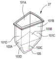
FIG. 12 is a perspective view of another embodiment of the storage box that may also be used as a dispensing box;
FIG. 13A is a front view of the storage box of FIG. 12;
FIG. 13B is a side view of the storage compartment shown in FIG. 12;
FIG. 13C is a side view of the storage case of FIG. 12;
FIG. 13D is a top view of the storage box of FIG. 12;
FIG. 14 is a perspective view of an embodiment of a housing or enclosure that the system of the present invention can accommodate during use;
FIG. 15 is a view of an embodiment of a computer screen for inputting information, displaying information and data, and controlling the system;
FIG. 16A is a flow chart illustrating an embodiment of a portion of the basic system operation when the storage bin is filled with medication;
FIG. 16B is a continuation of the flowchart of FIG. 16A;
FIG. 16C is a continuation of the flowchart of FIG. 16A;
FIG. 16D is a continuation of the flowchart of FIG. 16A;
FIG. 17 is a flow chart of an implementation routine of a basic program run by a computer for filling a dispensing reservoir at predetermined times for dispensing;
FIG. 18A is a perspective view of an embodiment of the apparatus of the present invention
FIG. 18B is a perspective view of an embodiment of the present invention for scanning information on a label of a prescription container onto the prescription container
FIG. 19 provides a perspective view of the housing of another variation of the grouping, storage and dispensing apparatus of the present invention;
fig. 20 provides internal perspective, side and top views of the variation of the invention shown in fig. 19.
FIG. 21 is a schematic structural view of the present invention;
FIG. 22 is a schematic view of the structure at the charge cup of the present invention;
FIG. 23 is a schematic view of the structure of the suction stirring claw of the present invention.
Detailed Description
The technical solutions in the embodiments of the present invention will be clearly and completely described below with reference to the drawings in the embodiments of the present invention, and it is obvious that the described embodiments are only a part of the embodiments of the present invention, and not all of the embodiments.
Example 1:
FIG. 1 is a block diagram of the main portions of an embodiment of the subject, a programmable computer controlling the operation of the system. The system includes a carousel assembly with storage bins and a dispensing bin 12, a robot assembly 13, which includes a vacuum or suction cup for taking the drug in the reservoir and moving the drug into the dispensing bin, and a vacuum system 14, which vacuum system 14 creates a vacuum so that the vacuum cup can grab the drug into the storage bin and move it into the dispensing bin. A pressure sensor and/or an air flow sensor 18 to determine if and when the vacuum cup has gripped a dose. Weight sensors 20 to authenticate the content storage and distribution boxes, and the like. The system includes communication capability 15 and power supply 17.
In this embodiment, fig. 2 is a top view of a carousel and robot, the assembly 13 of the drug dispensing device. Including a carousel and robotic arms. The periphery of the carousel is provided with a dispensing bin 29 and a plurality of storage bins 27 in fig. 2, there are 15 storage bins 27 that can store up to 15 different medications, with only one dispensing bin 29. In this embodiment the outer shape of the case is optimized to fit 16 cases on a carousel, 15 cases for storing drugs and 1 case for dispensing drugs. Each containing a specific drug at the discretion of the user, in the embodiment shown the conveyor 23 has a diameter of 10 inches and 16 bins around it have 15 storage spaces, 27 th and 29 th dispensing bins, the size of the conveyor and the number of bins can be varied as desired.
In this embodiment, the robot 25 has a vacuum probe 31 terminating in a vacuum cup 33. A vacuum probe elevation motor 37 is located on the upper portion of the robot 25, and a vacuum probe elevation motor 37 in the illustrated embodiment provides a means for raising and lowering the vacuum probe 31. Attached to the bottom of the robot arm is a robot arm rotating motor 35. Below the robot arm rotation motor is a carousel rotation motor 39, and fig. 3 is a top view of the carousel and robot 13, where the robot rotation motor 35 moves the robot 25 to the position where the vacuum probe 31 with the vacuum cup 33 is above the dispensing box 29 and the dispenser cup 36 is below the dispenser box. The vacuum probe 31 passes through a sleeve 46 at the edge of the robot arm support 48. The vacuum probe 31 can slide into the sleeve 46 by the up arrow 45 and the down arrow 47. The sleeve 46 keeps the vacuum probe 31 constrained against linear movement in the vertical direction. In addition, the carousel 23 is seen to rotate the motor 39. The rotary motor 39 is computer controlled and moves the conveyor belt as required, and figure 3 also provides a better vacuum probe 31 for connecting the hose 34 of the vacuum probe to the remaining pneumatic vacuum system 49. The flexible hose 34 has sufficient slack to allow the vacuum probe 31 to move up and down to insert the vacuum cup 33 into each of the medicine boxes to extract the medicine and then remove the medicine boxes so that the robot 25 can rotate the vacuum probe 31 to the next selected medicine box.
In this embodiment, fig. 4 provides a top view of carousel 12 and robot 13. The cable 40 is connected to the upper end of the vacuum probe 31 at one end and the vacuum probe 31 at the other end, and the cable 40 is connected to the pulley 42. When pulley 42 is rotated clockwise, cable 40 is wound around pulley 42 and when pulley 42 is rotated counterclockwise, cable 40 is wound around pulley 42 and drive belt 28 dynamically connects pulley 42 to drive shaft 44. The drive shaft 44 is driven by the motor 37. Thus, when the drive shaft 44 is moved clockwise by the movement of the belt 28 by the motor 37 and the pulley 42 is moved clockwise, the cable 40 goes to the reel on the pulley 42. This in turn causes probe 31 to move 45 upward. When the drive shaft 44 is moved counterclockwise by the motor 37 and belt 28, the pulley in the revolution counter rotates clockwise causing the cable 40 to slip off pulley 42, thereby causing the vacuum probe 31 to move down 47, the rotational movement of the robot 25 provided by the motor 35. The translational movement of the vacuum probe 31, up 45 and down 47, is connected to the end vacuum survey 31 by motor 37, pulley 42 and cable 40. The computer controls the robotic arm 25 to control the operation of the motor 35 and the motor 37 by rotating the robotic arm 25 to the position of the motor 35 and then lowering and raising the vacuum probe 31 to position the vacuum probe 31 on the selected storage or dispensing bin, with the motor 37 removing and delivering the medication from the bin to the dispensing bin. The hose 34 has sufficient slack to allow the vacuum probe 31 to move up and down while maintaining the integrity of the vacuum system seal.
In this embodiment, each bin 27 is filled with a particular medication prescribed by the patient using the medication dispensing system of the present invention in operation. In the version shown in fig. 2, 3 and 4, which is for up to 15 different drugs, referring to fig. 4, the robotic rotation motor 35 rotates the robotic arm 25 in either a clockwise 43 or counterclockwise 41 direction to place the vacuum probe 31 on the particular drug of the preselected storage bin 27 for dispensing.
In this embodiment, referring to fig. 2, when the elevation motor 37 is activated, the robotic arm moves 47 the vacuum probe 31 downward to enable the vacuum cup 33 to select a particular medication box number 27 for a dose of medication, and when the vacuum cup number 33 is in positive contact with the medication dose, the vacuum system is activated, creating a vacuum or suction effect, causing the vacuum cup to firmly hold the dose of medication. After sealing, the vacuum probe 31 is lifted 45, and the vacuum cup 33 with the attached medicine is detached from the medicine box 27. In addition, each case is agitated by a stirrer to shake it to remove potentially stuck medications, preventing the medications from being stored in each form of case 27, and the robotic arm 25 is then rotated clockwise or counterclockwise, as viewed in FIG. 3, until the vacuum probe 31, vacuum cup 33, and the held vacuum cups of medications are positioned above the dispensing or transfer bin 29. At this point, the dose of medication held by vacuum cup # 33 is released and falls into the dispensing box # 29.
In this embodiment, the system may switch from negative to positive air pressure to force or push the drug into the # 29 chamber. The robotic arm 25 moves sequentially into each of the bins, each of which has a particular medication to be dispensed to the patient at a predetermined time, picks it up with a vacuum cup, and deposits the medication into the dispensing bin 29. Until all patients are scheduled to take a predetermined time for a dose of medication in the dispensing box 29, fig. 5 is a block diagram of the basic components of the vacuum system 49 for movement, from box to box, of the dose of medication. The essential parts are a vacuum pump 51, a vacuum cup 33, a control valve 53, an airtight vacuum tube 55 connected to the vacuum cup 33 through a probe 31 of the vacuum pump 51, and pressure and air flow sensors 18. The power supply supplies energy to the system, and the computer controls the operation.
In this embodiment, the computer 11 positions the robot with the vacuum probe 31 and vacuum cup 33 over a preselected holding bin and lowers the vacuum probe 31 until the vacuum cup is involved in a medication dose stored in a medication bin and is in positive contact with the medication dose 83 in the medication bin and successfully takes a medication, and FIG. 9 provides an example of a cup 33 that attracts and holds medications 83 of different shapes and sizes. The vacuum pump is located in the robot arm 25 and is connected to the vacuum cup 33 through a vacuum air line 55, as shown in fig. 5. However, in an alternative embodiment the vacuum motor may be located near the end of the vacuum cup 33 and the survey 31.
In this embodiment, a pressure gauge or weight sensor may be used to determine when the vacuum cup 33 has used a dose of medication. In such a system, the computer 11 will turn on the vacuum pump 51 and control valve 53, create a vacuum in the air line 55 or below atmospheric pressure and cause the suction 33 cup to contact and pick up a dose, and grip under vacuum induction. Attached to one end of the body is 61 a metal connector threaded at 64 for connecting the vacuum cup 33 to the vacuum probe 31, the illustrated embodiment being connected to the remainder of the vacuum system 49, in turn, by a hose 34 and a vacuum air conduit 55. The vacuum end 67 of the vacuum cup is located at the end of the valve body 61 opposite the metal fitting 63. The body 61 of the vacuum cup 33 is hinged, in this embodiment in the form of a bellows structure 65 which adds flexibility and pliability to the cup 33 to safely create a secure air seal between the surface 68 and the dose matching medication.
In this example, the weight changed significantly. As shown in fig. 9, vacuum cup No. 33 is in the form of a ball and an egg, respectively, and vacuum end 67 of vacuum cup 33 has easily wrapped its contact surface around each dose of medication and held firmly by vacuum suction created at orifice plate 69. FIG. 9 is for illustration only; so that the vacuum end 67 of the vacuum cup can form a complete seal so that the pill can be grasped and moved without dropping. Bellows 65 is added in part to the vacuum cup 33 to provide greater flexibility, as shown in fig. 5, 6, 7, and 8, and vacuum or suction end 67 is formed by a large lip-like structure that extends outwardly, like a disk-shaped flange 70, to form a pill contact surface 68 adjacent an aperture 69.
In this embodiment, fig. 11A is a perspective view of one embodiment of the storage box 27. For ease of illustration, in FIG. 11A, the interior surface of the case is shown in phantom. The 27 th bin has four upper portions 101A, 101B, 101C and 101D, and the medicine boxes can hold a plurality of tablets or other similar medicines. 101A, 101B, 101C, and 101D have steeper facing bottom slopes, and walls 103A, 103B, 103C, 103D, due to their steepness, form a funnel terminating in a closed v-shaped bottom 105.
In this example, collection 115 wells are started. The collection well 115 is composed of a portion of sides 113A, 113B, 113C and 109B. Shoulder 114A connects side 109A with side 113A and shoulder 114B connects side 109C with side 113B. The bottom of 107 consists of the bottom of 117. It can be seen that the drug is extracted from well 107 down the 159B well wall into well 115 as the robotic arm is operated. It can be seen that the dose of medication is extracted from the holding tank 107 and the remaining dose is the medication which will naturally fall down 115 wells until the trash can is empty. The recovery bin 107 may also serve as a dispenser or delivery bin 29 if for some reason the dose of medication is recorded and a non-moving trash can be shaken, each bin having its own vibration mechanism. The only modification is that the bottom 117 is removed to form an open bottom through which doses of medicament can be dropped into 36 containers, as shown in figures 2 and 3, placed below the opening to form 117 to collect doses of medicament, and the robotic arm stores the medicament in a dispensing or delivery box.
In this embodiment, FIG. 15 is an embodiment of a computer display 161 that would appear on the graphical user interface 153 and be saved to the computer upon depression of the enter key 173. FIG. 16A is a flow chart of the initial steps of the basic bin loading procedure described above. When it is desired to place a medication in the system, the user clicks on the screen 201 to activate the system.
In this embodiment, the option of scanning the prescription container label or the information sheet image is provided in FIG. 16C. The computer will be programmed with the required optical character recognition software (OCR) and additional software to load the drug into the system for review and correction and then finalization, fig. 18A provides a view of an embodiment of the system for scanning, the material being from a form provided by the pharmaceutical factory that carries the prescription material. 303 pages will be processed by the imaging device 301 in a standard manner.
In this embodiment, FIG. 20 provides a side view of the internal mechanism of a variation device 401 of the present invention. The rotating motor 419 is a rotating and position rotating hobby horse 23 controlled by a computer. The actuator 423 or vacuum probe rotary motor positioning device is comprised of a rotary motor 427 and arm 429. A rotary motor 427, controlled by a computer, moves arm429 in a rotary motion. The vacuum probe 417 is connected to the end of arm429 by a rotary motor 427 and by moving arm429 by the rotary motor 427 the vacuum probe 417 is placed on the selected medicine box 27 and the medicine is extracted from the selected medicine box 27 and placed into a dispensing cup, fig. 20 providing a top view of the internal mechanism of the apparatus 401 with the cover 425 removed. As the boxes are filled with medication, the conveyor is rotated to place the selected cases for a particular medication in sequence under the 409 chute. Arm429 is then rotated by rotary motor 427 to be placed over storage tank 27 along with the preselected medication. The rotating arm then places itself over the dispensing port 421 above the dispensing cup.
The above description is only for the preferred embodiment of the present invention, but the scope of the present invention is not limited thereto, and any person skilled in the art should be considered to be within the technical scope of the present invention, and the technical solutions and the inventive concepts thereof according to the present invention should be equivalent or changed within the scope of the present invention.
Claims (10)
1. An automatic medicine dispensing box with an automatic medicine dispensing function is characterized by comprising:
a. a conveyor belt provided with a plurality of medicine boxes on the periphery, wherein one of the medicine boxes is a medicine dispensing box, and the rest medicine boxes are storage boxes of specific medicines;
a robotic arm capable of positioning an extracted dose, withdrawing a drug from the storage bin, and storing the extracted drug in the dispensing bin;
c. said robotic arm having a vacuum probe and a vacuum probe at a distal end connected to a vacuum induction system and a proximal end said bottom of year vacuum probe connected to a vacuum cup hinge body enclosed chamber interior and a centrally apertured vacuum cup representation, the bottom of year leading to an interior cavity wherein said interior cavity is in fluid communication through an interior passage of said probe having said vacuum induction system;
d. the vacuum end of the vacuum cup positions a dose of medicament on the probe contact surface from the vacuum cup, and in the beginning of the vacuum induction system, the vacuum end of the vacuum cup firmly holds the dose of medicament, and the manipulator moves the dose of medicament to the dosing box;
e. a computer controller system in which a particular medication stored in a particular identified bin is registered and in which controller system controls operation of the robotic arm to direct the robotic arm to extract a dose of medication from a designated bin and deposit the dose of medication in the dispensing bin at a predetermined time.
2. The apparatus set forth in claim 1 wherein said bin is shaped such that said robotic arm providing said medication doses to said robotic arm (e.g., vacuum cups on said probe) connected to said robotic arm may engage said robotic arm at predetermined locations on said robotic arm, wherein said bin is shaped such that it has a larger upper storage area and a lower funnel area, said lower funnel area narrowing to an end point to which a medication dose stored in a medication box will be drawn when other doses in said medication box are removed.
3. The device of claim 1, wherein the hinge body comprises an inner cavity having at least one bellows portion adjacent the vacuum end, the vacuum end being a wide flexible surface surrounding the hole, wherein the hole of the vacuum cup is less than one-quarter of the size of the vacuum end, wherein the hole has a diameter of 0.25 inches and the vacuum end has a diameter of 1.25 inches.
4. The device of claim 1, comprising a housing for covering and containing said device for organizing and dispensing a plurality of medications, said housing having at least one compartment on the periphery thereof for storing a non-medication, said compartment containing a medication to be dispensed from a container selected from a group of medications, in the form of a solid medication dose; inhaler, ointment tube and syringe, wherein the vacuum cup with an articulated body comprises at least two bellows portions, wherein the computer determines whether the vacuum cup has been dosed with a medicament and holds tightly on a selected event from a group of events comprising a change in air pressure, a change in air flow, a change in force and a change in weight after receiving a signal an.
5. The apparatus of claim 1 including means for scanning printed statements wherein prescription information for a medication is stored in a specific storage box in said computer controller system and software including optical character recognition software, said prescription information being converted in a form usable by said computer controller system to determine when to dispense the medication identified in the prescription information, said means for printing a statement being selected from the group consisting of a label on the prescription container and a form containing the prescription information, wherein said vacuum system inducing system is capable of reversing air flow to purge particulate matter introduced into said vacuum inducing system from a dose of medication held by said vacuum cup.
6. The apparatus of claim 1, including communication means for enabling said computer to transmit a signal having predetermined information to an electronic device communication device, the claim means for selecting said electronic communication means being comprised from a selected group of cell phones, tablets, computers or regular cell phones.
7. A system for dispensing a plurality of medicaments in solid dose form to an individual comprising:
a. a programmable computer for controlling the operation of the system;
b. the rotary trojan rotates around the center point thereof, the periphery of the rotary trojan is provided with a plurality of storage boxes, and the periphery of the rotary trojan is provided with at least one delivery box;
c. a robotic arm with a vacuum probe, wherein said robotic arm is configured to be movable within said boxes and to insert said vacuum probe into any of said boxes to provide a plurality of storage bins and at least one delivery bin as directed by said computer;
d. a vacuum generating device connected to the first end of the probe;
e. a vacuum cup having an articulating body surrounding an interior space, attached to a second end of the probe, the vacuum generating device in fluid communication with the interior space of the vacuum cup
The probe has a hollow interior forming a fluid connection therebetween;
f. said vacuum cup having a wide, soft pill-contacting surface surrounding an aperture to said interior space of said cup; and
g. wherein the second end of said probe is inserted into any one of said plurality of storage bins, the pill contacting surface of said vacuum cup contacts said dosage of medication and creates a vacuum, said vacuum cup device is operating and it can firmly grip said dosage of medication and continue to hold it until said robotic arm moves it to the location of said delivery bin, i.e., the location where said computer system terminates the gripping of said dosage of medication by said cup and deposits said dosage into said delivery bin.
8. The system of claim 7, wherein said computer terminating said vacuum cup's holding of said dosage of medication by generating a signal initiating a selected action consists of terminating operation of said vacuum inducer and by reversing an air flow instrument between said vacuum cup and said vacuum inducer, said computer determining whether said vacuum cup is safely holding a dosage of medication by receiving a signal of an event selected from the group consisting of a change in air pressure, a change in air flow, a change in force, and a change in weight, wherein said vacuum cup's hinge is located in at least one bellows section near said wide and flexible pill contacting surface of said vacuum cup, further comprising a device for scanning printed prescription information statements, storing medication in a specific storage box, said computer controller system, and software including optical recognition character software, converting, in the computer controller system, the prescription information into a form usable by the computer controller system to determine when to dispense the medication identified in the prescription information, the system for printing a report being selected from a group consisting of a label on a prescription container and a form containing the prescription information.
9. A method of periodically dispensing a plurality of medications to at least one person, comprising the steps of:
a. a plurality of storage bins are provided for storing doses of a particular medicament,
each of the plurality of bins is designated to store a dose of only one designated medication;
b. providing a probe having a suction cup at a probe end, said probe end having a suction cup movable between said storage bins, said probe being actuatable to grasp a dose of medicament on any one of said medicament bins, connecting a pneumatic vacuum system to said suction cup, and moving said probe with said suction cup to grasp a dose on said suction cup in a delivery bin and into said delivery bin, wherein said suction cup has a hollow interior system in communication with a vacuum at an opening at a first end of said suction cup hinge, and a large lip surface at said second end, said large lip surface having a hole in its center that opens into said hollow interior, said suction cup being made of a soft, pliable rubber-like material;
c. providing a computer system programmed to control operation of said probe and to connect said probe and said suction cup together for sequential operation:
1. moving a preset dose of medication from the medication box to the delivery box using the probe and suction cup for a preset time;
2. indicating that said delivery box is filled with a predetermined dose for consumption by the patient within a predetermined time;
3. continuing to signal that a dose of medication is ready for use until a sensor indicates that a dose is ready for removal from the delivery box;
4. recording in the memory of the computer the fact that a dose of medication has been removed from the delivery box;
5. providing the information of the dosage amount of the medicine, and recording the information to delivery boxes of different nursing personnel and providers; and periodically performing a cleaning cycle to remove particulate matter from the probe and the chuck.
10. The method of claim 9 including programming said computer to load doses of medication into pre-designated bins of said plurality of said bins;
the method comprises the following steps:
a. starting a computer program to start a drug dose loading program;
b. indicating whether the dosage of medication to be loaded is a new prescription or whether an existing prescription has been stored in a designated storage bin;
c. if the prescription has been designated as an existing prescription already stored within the designated storage bin, the following sub-routine is run:
1. reviewing existing prescription information in the computer system;
2. correcting information in the computer system according to the selected prescription; and
3. verifying the correctness of the information after the step c.ii is completed;
4. storing a new mediation dosage of an existing prescription in the specified storage box;
d. if the recipe is new, the following sub-routine is run:
1. designating an available empty storage box from the plurality of storage boxes for storage
The new prescription will be stored;
2. inputting information about the new prescription into the computer system;
3. confirming that the new prescription information is correct;
4. manually inputting information on the prescription through a computer touch screen, scanning the prescription information in the image from a label or a sheet, wherein the step of inputting the prescription information is a step of inputting the following information on the prescription:
1. the name of the drug;
2. a prescribing physician;
3. number of doses inserted;
4. the amount of each dose;
5. time and dosage of administration.
Priority Applications (1)
| Application Number | Priority Date | Filing Date | Title |
|---|---|---|---|
| CN201910660115.6A CN110772427A (en) | 2019-07-22 | 2019-07-22 | Automatic medicine distributing box with automatic medicine distributing function |
Applications Claiming Priority (1)
| Application Number | Priority Date | Filing Date | Title |
|---|---|---|---|
| CN201910660115.6A CN110772427A (en) | 2019-07-22 | 2019-07-22 | Automatic medicine distributing box with automatic medicine distributing function |
Publications (1)
| Publication Number | Publication Date |
|---|---|
| CN110772427A true CN110772427A (en) | 2020-02-11 |
Family
ID=69383846
Family Applications (1)
| Application Number | Title | Priority Date | Filing Date |
|---|---|---|---|
| CN201910660115.6A Pending CN110772427A (en) | 2019-07-22 | 2019-07-22 | Automatic medicine distributing box with automatic medicine distributing function |
Country Status (1)
| Country | Link |
|---|---|
| CN (1) | CN110772427A (en) |
Cited By (1)
| Publication number | Priority date | Publication date | Assignee | Title |
|---|---|---|---|---|
| CN113978938A (en) * | 2020-10-26 | 2022-01-28 | 北京印刷学院 | Medicine surplus detection system and method for medicine storage device |
Citations (8)
| Publication number | Priority date | Publication date | Assignee | Title |
|---|---|---|---|---|
| CN103142412A (en) * | 2012-12-19 | 2013-06-12 | 苏州艾隆科技股份有限公司 | Medicine dispensing method and system of automatic medicine dispensing machine |
| CN103238166A (en) * | 2011-02-14 | 2013-08-07 | 株式会社汤山制作所 | Verification device for dispensing of pharmaceuticals |
| CN105726317A (en) * | 2016-03-23 | 2016-07-06 | 王志宏 | Automatic medicine dispensing device |
| CN106377426A (en) * | 2016-09-29 | 2017-02-08 | 哈尔滨医科大学 | Automatic dosing device for injector |
| CN106794116A (en) * | 2014-10-31 | 2017-05-31 | 株式会社汤山制作所 | Medication dispensing device |
| CN108910530A (en) * | 2018-08-31 | 2018-11-30 | 上海擅韬信息技术有限公司 | A kind of fetching device |
| CN208499523U (en) * | 2018-08-01 | 2019-02-15 | 河北盛世天昕电子科技有限公司 | Dispenser device and dispensing system |
| CN208629468U (en) * | 2018-08-01 | 2019-03-22 | 河北盛世天昕电子科技有限公司 | Vacuum machine arm device and dispensing system |
-
2019
- 2019-07-22 CN CN201910660115.6A patent/CN110772427A/en active Pending
Patent Citations (8)
| Publication number | Priority date | Publication date | Assignee | Title |
|---|---|---|---|---|
| CN103238166A (en) * | 2011-02-14 | 2013-08-07 | 株式会社汤山制作所 | Verification device for dispensing of pharmaceuticals |
| CN103142412A (en) * | 2012-12-19 | 2013-06-12 | 苏州艾隆科技股份有限公司 | Medicine dispensing method and system of automatic medicine dispensing machine |
| CN106794116A (en) * | 2014-10-31 | 2017-05-31 | 株式会社汤山制作所 | Medication dispensing device |
| CN105726317A (en) * | 2016-03-23 | 2016-07-06 | 王志宏 | Automatic medicine dispensing device |
| CN106377426A (en) * | 2016-09-29 | 2017-02-08 | 哈尔滨医科大学 | Automatic dosing device for injector |
| CN208499523U (en) * | 2018-08-01 | 2019-02-15 | 河北盛世天昕电子科技有限公司 | Dispenser device and dispensing system |
| CN208629468U (en) * | 2018-08-01 | 2019-03-22 | 河北盛世天昕电子科技有限公司 | Vacuum machine arm device and dispensing system |
| CN108910530A (en) * | 2018-08-31 | 2018-11-30 | 上海擅韬信息技术有限公司 | A kind of fetching device |
Cited By (1)
| Publication number | Priority date | Publication date | Assignee | Title |
|---|---|---|---|---|
| CN113978938A (en) * | 2020-10-26 | 2022-01-28 | 北京印刷学院 | Medicine surplus detection system and method for medicine storage device |
Similar Documents
| Publication | Publication Date | Title |
|---|---|---|
| US11896556B1 (en) | Apparatus and method for dispensing medication | |
| US5838575A (en) | System for dispensing drugs | |
| US6732884B2 (en) | Bulk medication dispenser and monitoring device | |
| EP3429547B1 (en) | Automated medication adherence system | |
| US5812410A (en) | System for dispensing drugs | |
| CA2922451C (en) | Object dispenser having a variable orifice and image identification | |
| US6607094B2 (en) | Apparatus and method for dispensing medication | |
| US8596309B2 (en) | Medication mixing device and medication mixing method | |
| US20060213921A1 (en) | Pill dispensing apparatus | |
| JPH08511963A (en) | Vacuum actuated medicine dispensing device | |
| CN105726317A (en) | Automatic medicine dispensing device | |
| WO2006119306A2 (en) | Items dispenser | |
| EP3953912A1 (en) | Handling medication receptacles by pharmaceutical dispensing system and method | |
| US20190228852A1 (en) | Automated Medication Adherence System | |
| CN110772427A (en) | Automatic medicine distributing box with automatic medicine distributing function | |
| Brolin et al. | Design of automated medicine vending machine using mechatronics techniques | |
| CN112076087A (en) | Facial recognition dispensing device based on database | |
| US11285083B1 (en) | Apparatus and method for dispensing medication | |
| JP6274319B2 (en) | Drug packaging device | |
| KR102451175B1 (en) | Dispensing canisters for packaging pharmaceuticals via robotic technology | |
| CN214058432U (en) | Intelligent medicine box | |
| US5016766A (en) | Anti-contamination orthodontic device dispenser | |
| CN115285523B (en) | Storage box capable of timing and automatic batching | |
| US20240358591A1 (en) | Enhanced inspection of medicaments after loading of blister card prescriptions | |
| US11980748B2 (en) | Cartridge loading system for syringe caps |
Legal Events
| Date | Code | Title | Description |
|---|---|---|---|
| PB01 | Publication | ||
| PB01 | Publication | ||
| SE01 | Entry into force of request for substantive examination | ||
| SE01 | Entry into force of request for substantive examination | ||
| RJ01 | Rejection of invention patent application after publication |
Application publication date: 20200211 |
|
| RJ01 | Rejection of invention patent application after publication |