CN1107171C - Mounting device - Google Patents
Mounting device Download PDFInfo
- Publication number
- CN1107171C CN1107171C CN97199618A CN97199618A CN1107171C CN 1107171 C CN1107171 C CN 1107171C CN 97199618 A CN97199618 A CN 97199618A CN 97199618 A CN97199618 A CN 97199618A CN 1107171 C CN1107171 C CN 1107171C
- Authority
- CN
- China
- Prior art keywords
- cover
- nut
- flange
- overcoat
- machine parts
- Prior art date
- Legal status (The legal status is an assumption and is not a legal conclusion. Google has not performed a legal analysis and makes no representation as to the accuracy of the status listed.)
- Expired - Fee Related
Links
- 238000006073 displacement reaction Methods 0.000 claims abstract description 46
- 230000008602 contraction Effects 0.000 claims abstract description 7
- 210000003205 muscle Anatomy 0.000 claims description 17
- 238000000034 method Methods 0.000 claims description 8
- 230000011218 segmentation Effects 0.000 claims 4
- 230000000694 effects Effects 0.000 abstract description 3
- 239000000463 material Substances 0.000 abstract description 3
- 238000004873 anchoring Methods 0.000 abstract 1
- 230000013011 mating Effects 0.000 abstract 1
- 238000000926 separation method Methods 0.000 description 4
- 238000000638 solvent extraction Methods 0.000 description 4
- 230000004323 axial length Effects 0.000 description 3
- 229910000831 Steel Inorganic materials 0.000 description 2
- 238000009434 installation Methods 0.000 description 2
- 238000004519 manufacturing process Methods 0.000 description 2
- 230000001737 promoting effect Effects 0.000 description 2
- 239000010959 steel Substances 0.000 description 2
- 238000012986 modification Methods 0.000 description 1
- 230000004048 modification Effects 0.000 description 1
- 238000007634 remodeling Methods 0.000 description 1
Images


Classifications
-
- F—MECHANICAL ENGINEERING; LIGHTING; HEATING; WEAPONS; BLASTING
- F16—ENGINEERING ELEMENTS AND UNITS; GENERAL MEASURES FOR PRODUCING AND MAINTAINING EFFECTIVE FUNCTIONING OF MACHINES OR INSTALLATIONS; THERMAL INSULATION IN GENERAL
- F16D—COUPLINGS FOR TRANSMITTING ROTATION; CLUTCHES; BRAKES
- F16D1/00—Couplings for rigidly connecting two coaxial shafts or other movable machine elements
- F16D1/06—Couplings for rigidly connecting two coaxial shafts or other movable machine elements for attachment of a member on a shaft or on a shaft-end
- F16D1/08—Couplings for rigidly connecting two coaxial shafts or other movable machine elements for attachment of a member on a shaft or on a shaft-end with clamping hub; with hub and longitudinal key
- F16D1/09—Couplings for rigidly connecting two coaxial shafts or other movable machine elements for attachment of a member on a shaft or on a shaft-end with clamping hub; with hub and longitudinal key with radial clamping due to axial loading of at least one pair of conical surfaces
- F16D1/093—Couplings for rigidly connecting two coaxial shafts or other movable machine elements for attachment of a member on a shaft or on a shaft-end with clamping hub; with hub and longitudinal key with radial clamping due to axial loading of at least one pair of conical surfaces using one or more elastic segmented conical rings forming at least one of the conical surfaces, the rings being expanded or contracted to effect clamping
- F16D1/094—Couplings for rigidly connecting two coaxial shafts or other movable machine elements for attachment of a member on a shaft or on a shaft-end with clamping hub; with hub and longitudinal key with radial clamping due to axial loading of at least one pair of conical surfaces using one or more elastic segmented conical rings forming at least one of the conical surfaces, the rings being expanded or contracted to effect clamping using one or more pairs of elastic or segmented rings with mutually mating conical surfaces, one of the mating rings being contracted and the other being expanded
-
- F—MECHANICAL ENGINEERING; LIGHTING; HEATING; WEAPONS; BLASTING
- F16—ENGINEERING ELEMENTS AND UNITS; GENERAL MEASURES FOR PRODUCING AND MAINTAINING EFFECTIVE FUNCTIONING OF MACHINES OR INSTALLATIONS; THERMAL INSULATION IN GENERAL
- F16B—DEVICES FOR FASTENING OR SECURING CONSTRUCTIONAL ELEMENTS OR MACHINE PARTS TOGETHER, e.g. NAILS, BOLTS, CIRCLIPS, CLAMPS, CLIPS OR WEDGES; JOINTS OR JOINTING
- F16B7/00—Connections of rods or tubes, e.g. of non-circular section, mutually, including resilient connections
- F16B7/10—Telescoping systems
- F16B7/14—Telescoping systems locking in intermediate non-discrete positions
- F16B7/149—Telescoping systems locking in intermediate non-discrete positions with a sleeve or ring having a tapered or conical surface
-
- Y—GENERAL TAGGING OF NEW TECHNOLOGICAL DEVELOPMENTS; GENERAL TAGGING OF CROSS-SECTIONAL TECHNOLOGIES SPANNING OVER SEVERAL SECTIONS OF THE IPC; TECHNICAL SUBJECTS COVERED BY FORMER USPC CROSS-REFERENCE ART COLLECTIONS [XRACs] AND DIGESTS
- Y10—TECHNICAL SUBJECTS COVERED BY FORMER USPC
- Y10T—TECHNICAL SUBJECTS COVERED BY FORMER US CLASSIFICATION
- Y10T403/00—Joints and connections
- Y10T403/70—Interfitted members
- Y10T403/7047—Radially interposed shim or bushing
- Y10T403/7051—Wedging or camming
- Y10T403/7052—Engaged by axial movement
- Y10T403/7054—Plural, circumferentially related shims between members
-
- Y—GENERAL TAGGING OF NEW TECHNOLOGICAL DEVELOPMENTS; GENERAL TAGGING OF CROSS-SECTIONAL TECHNOLOGIES SPANNING OVER SEVERAL SECTIONS OF THE IPC; TECHNICAL SUBJECTS COVERED BY FORMER USPC CROSS-REFERENCE ART COLLECTIONS [XRACs] AND DIGESTS
- Y10—TECHNICAL SUBJECTS COVERED BY FORMER USPC
- Y10T—TECHNICAL SUBJECTS COVERED BY FORMER US CLASSIFICATION
- Y10T403/00—Joints and connections
- Y10T403/70—Interfitted members
- Y10T403/7047—Radially interposed shim or bushing
- Y10T403/7051—Wedging or camming
- Y10T403/7052—Engaged by axial movement
- Y10T403/7058—Split or slotted bushing
Abstract
A mounting device (10) for coaxially anchoring a machine element (11) upon a rotary shaft (12). Device (10) fits between the interior bore of machine element (11) and the cylindrical surface of shaft (12) and is effective to position element (11) at any desired position longitudinally of shaft (12) and at any angular position circumferentially of shaft (12). Device (10) has inner and outer sleeves (20,50), the mating surfaces of which are similarly tapered so that relative axial dispacement of the sleeves (20, 50) effects expansion and contraction of the interior bore and external surface of the combined elements. Rotation of a threaded nut (40) at one end of device (10) effects the relative axial displacement of inner and outer sleeves (20,50) to afford expansion and contraction of outer sleeve (50) without straining the material of sleeve (50) or nut (40).
Description
The field of the invention
The present invention relates to machine parts is installed in fixing device on the axle, its means of fixation makes the rotation of axle that its all torsion torque is passed to machine parts and can not produce because of the install machinery part and skid.Particularly, device of the present invention provides a kind of improved fixing device for the install machinery part, it allows the machine parts on the axle unrestrictedly to adjust at the axial and circumferential both direction of axle, and this fixing device is installed in machine parts the axial position that after axle is gone up machine parts will be maintained fixed.
Background of the present invention
As everyone knows, machine parts (for example belt pulley and gear) is installed in the axle on to use certain device.One of difficult problem is that the existing apparatus that machine parts is installed on the cylindrical shaft is used inconvenience.For example, many of some matching requirements assemblings and adjust several screws, the axle remodeling of other matching requirements install machinery parts.
Another difficult problem that often runs into relates to the pinpoint needs of machine parts, and promptly it should accurately be positioned at a fixing axial position when machine parts is installed in when spool last.Can run into an above-mentioned difficult problem when fastening fixing device, along installation surface trend in axial sliding, this is because the axial force that the fixing device part conical surface produces to this difficult problem from machine parts.
Summary of the present invention
Fixing device of the present invention is easy to use.This device makes the installation of machine parts just can produce frictional engagement by only tightening a nut, and just can be disengaged by unclamping same nut.This nut is used for throwing off really the frictional engagement that produces by fastening nut.In addition, this fixture structure is simple and manufacture cost is quite low.
The present invention has also solved a difficult problem that makes machine parts be maintained fixed the position.In case the axial position that this fixing device just makes the above-mentioned relatively axle of machine parts be maintained fixed is installed.
Be used for the coaxial device that is installed on the cylindrical shaft of porose machine parts is comprised the overcoat that engages with machine parts, be with the cylindrical outer surface that inner conical surface and external diameter equate with the machine parts aperture outside this.Axial groove along above-mentioned overcoat longitudinal extension allows the outer surface of this overcoat to expand.Being enclosed within the one end outside above-mentioned also has internal thread, and it is connected with corresponding externally threaded nut thread is arranged.Above-mentioned nut has the annular flange that is connected with the inner sleeve.
Be with the endoporus that male cone (strobilus masculinus) that its cone angle equates with above-mentioned overcoat inner conical surface cone angle and aperture equate with the above-mentioned cylindrical shaft diameter of axle in above-mentioned.Be with the annular interlocking portion that makes that cover is connected with above-mentioned nut in this in above-mentioned.Should also there be a plurality of axial grooves to shrink by interior cover with the endoporus that allows to overlap in this along its longitudinal extension.The orientation of above-mentioned groove and structure make above-mentioned in tackling prepare enough enough flexibilities so that should in the annular interlocking portion deformable of cover cross above-mentioned nut.
Rotate above-mentioned nut and make above-mentioned overcoat produce axial displacement, and this nut produces axial displacement in opposite direction with making this interior cover being connected of above-mentioned interior cover along a direction with respect to this nut.Expand in the hole that the cover and the relative displacement of overcoat cause the outer surface of overcoat to be close to machine parts in above-mentioned and the endoporus of interior cover is close to the cylindrical shaft contraction, makes that machine parts is coaxial to be installed on the cylindrical shaft.
Be used for the coaxial second kind of device that is installed on the axle of porose machine parts comprised the single-piece overcoat that contacts with machine parts.Should outer be with the outer surface that inner conical surface and external diameter equate with the machine parts aperture.Should outer be with near the internal thread of one end and the ring-shaped bearing portion of inwardly stretching out in distal radial.Above-mentioned support face is against the cylindrical bush around above-mentioned axle.The cylindrical hole that above-mentioned lining has the aperture to equate with the above-mentioned diameter of axle.There is externally threaded nut to be connected near the one end with above-mentioned sleeve thread.Above-mentioned nut has first annular flange at far-end, this flange be connected with interior cover between the above-mentioned lining at above-mentioned overcoat.Be with the male cone (strobilus masculinus) that its cone angle equates with above-mentioned overcoat inner conical surface cone angle in above-mentioned.Cover also has second flange that is connected with first flange of above-mentioned nut in above-mentioned.Be positioned at the bias piece of above-mentioned nut bore, the one end leans against on the above-mentioned lining, above-mentioned lining is pressed to the support of above-mentioned overcoat.
Rotate above-mentioned nut and make above-mentioned overcoat produce axial displacement, and this nut produces axial displacement in opposite direction with making this interior cover being connected of above-mentioned interior cover along a direction with respect to nut.Expand in the hole that the cover and the relative displacement of overcoat cause the outer surface of overcoat to be close to machine parts in above-mentioned and the endoporus of interior cover is close to the lining contraction, causes lining to shrink towards cylindrical shaft then, makes that machine parts is coaxial to be installed on the cylindrical shaft.
Brief description of the drawings
The above-mentioned summary and the preferred embodiment of the present invention of describing in detail are below read in conjunction with the accompanying drawings and can better be understood, in the accompanying drawings:
Fig. 1 is the exploded perspective view of fixing device of the present invention, and it is connected to machine parts on the axle;
Fig. 2 is the end elevation (from the right side of Fig. 1) of assembling fixing device;
Fig. 3 is the cross-sectional view in 3-3 cross section among Fig. 2;
Fig. 4 is second embodiment's of a fixing device of the present invention cross-sectional view;
Fig. 5 is the 3rd embodiment's of a fixing device of the present invention cross-sectional view;
Fig. 6 is the 4th embodiment's of a fixing device of the present invention exploded perspective view (having removed axle);
Fig. 7 is the assembling fixing device stereogram of modification embodiment illustrated in fig. 6.
DETAILED DESCRIPTION OF THE PREFERRED
Referring now to accompanying drawing,, especially referring to Fig. 1 to Fig. 3, as shown in the figure, fixing device 10 is used for the cover of machine parts 11 is fixed on cylindrical shaft 12.In the present embodiment, machine parts 11 has smooth cylindrical hole 13, the axis coaxle of this axially bored line and axle 12 barrel surfaces.This fixing device between hole 13 and axle 12, its in the hole 13 and 12 on axle expand so that machine parts 11 is fastened on the axle reliably in the axial random desired location and the circumferential any angular position of axle 12.
As shown in Figure 3, the internal surface of overcoat 50 tilts towards front end or far-end 51 with the tapering identical with interior cover 20.This shows, when overcoat 50 with respect to interior cover 20 backward during displacement (in Fig. 3 from left to right), the conical surface of interior cover and overcoat contacts, the outer surface of overcoat is expanded, the internal surface of cover 20 shrinks in making, and the pucker ﹠ bloat on above-mentioned surface is parallel to the common center axis of this builtup member substantially.
As shown in the figure, there is internal thread the rear end of overcoat 50.Helical thread portion 52 is near the rear end of overcoat, stops to the cone-shaped inner surface section start.As mentioned above, the groove 54 on the overcoat 50 begins to extend from front end 51, is stopping before the rear end.This shows that the free end portion of sleeve thread end is the continuous entity of the annular of unslotted.This annular entity of overcoat can possess higher screw strength and improve the situation that is threaded with nut 40 with comparing along the overcoat of its whole axial length fluting.
Overcoat 50 passes through nut 40 with respect to interior cover 20 displacements.For this reason, as shown in figures 1 and 3, the outside thread 42 of nut 40 is connected with the internal thread 52 of overcoat 50.Turning nut 40 makes it with respect to overcoat axial displacement.Because interior cover 20 is connected (as described below) with nut 40, when the nut displacement in the cover with respect to the overcoat displacement.
This nut has an endoporus greater than axle 12 diameters of axle.In addition, the external diameter of this nut is less than the external diameter of overcoat 50.This shows that when not fastening, fixing device can be passed the hole 13 of machine parts 11, therefore, can fixing device be fastened on the axle from both direction.
According to the present invention, nut 40 and interior cover 20 interlockings are so that the male cone (strobilus masculinus) that overlaps in when turning nut can slide up and down along the inner conical surface of overcoat 50.When the direction of front end 51 was upwards slided, the inner conical surface of overcoat was fastened on interior cover 20 on the axle 12 and overcoat 50 is fastened in the hole 13 of part 11.This conical surface unclamps fixing device 10 when lower slider.For nut is connected with interior cover, nut 40 has annular flange 48 that radial outward stretches out and near the outer groove 46 of this flange, and sidewall is substantially perpendicular to the common axis line of this builtup member before and after this groove.Nut outward flange 48 and annular groove 46 embed mutually with the inner flange 24 and the annular groove 26 of interior cover.Say the annular groove 26 of cover in the outward flange 48 of nut embeds, the annular groove 46 of inner flange 24 insert nuts of interior cover exactly.For this purpose, the width of nut outward flange 48 is slightly smaller than the width of inner sleeve groove 26, and the width of interior cover inner flange 26 is slightly smaller than the width of nut annular groove 46.This shows that make it with respect to overcoat 50 backward during displacement when turning nut, the ear end face of nut outward flange 48 is in the face of the rear wall of inner sleeve groove 26, thus the pressure axial motion backward of cover 20 in realizing.Similarly, make it with respect to overcoat 50 forward during displacement when turning nut, the front-end face of nut outward flange 48 is in the face of the antetheca of inner sleeve groove 26, and the ear end face of interior cover inner flange 24 is in the face of the rear wall of nut 40 annular grooves, thus the pressure axial motion forward of cover in realizing.
The internal diameter of interior cover inner flange 24 is less than the external diameter of nut outward flange 48, and interior cover flange must be crossed the nut flange so that interior cover is connected with nut.Therefore, be connected with nut in order to make whole interior cover, enough flexibilities must be arranged interior cover so that interior cover surpasses the outwardly directed flange expansion of nut.For this purpose, interior cover 20 is by forming a plurality of partitioning portions from interior cover rear end along its axially extended groove 22.As shown in Figure 3, except groove 22a, all the other grooves all stop along the front end 29 inside lines at interval with interior cover 20.The terminal of groove 22 together with groove 22a, provides the muscle 32 of separation, the partitioning portion of muscle 32 cover in front end 29 connects.In the present embodiment, in apply mechanically 1215 steel and make, have six width and be about 5/64 inch equidistant groove, one of them is groove 22a, five is end slot in addition., will be appreciated that number, width, length and the pitch of grooves that can change groove is to reach necessary flexibility.Can see very clearly that from Fig. 3 stop before the front end of end slot 22 cover in arriving, muscle 32 is the thickest at front end 29 places of interior cover, the thickness that rear end 21 directions that muscle 32 overlaps are inwardly extended reduces gradually.This shows, but in enough for a short time the making of axial length of front end 29 place's muscle 32, overlap radial deformation so that interior cover is connected with nut.
By overlapping on nut, promoting interior cover 20 is assembled on the nut 40 with following mode.Be enclosed within making after the nut and its axial alignment, rear end 21 axial displacements of cover engage with nut outward flange 26 in making.When interior cover and nut engages, interior cover distortion also surpasses the expansion of nut outward flange 26 radially outwards.For ease of this radial expansion, the ear end face of interior cover inner flange 24 is as shown in Figure 3 in 28 place's chamferings.Interior cover moves past nut outward flange 48 with respect to the nut back displacement until interior cover inner flange 24.The annular groove 46 of inner flange 24 insert nuts of cover in the cover elastic shrinkage makes then, the annular groove 26 of cover in nut outward flange 48 embeds.Like this, interior cover 20 is lived by the nut fixed constraints.
During work, it should be noted that cover in making by fastening nut 40 and the conical surface of overcoat upwards is close to and relative displacement makes fixing device forced engagement between the hole 13 of part 11 and axle 12, on the other hand.The endoporus of cover 20 shrank in this displacement made, and the outer surface of overcoat 50 is expanded.Equally, by oppositely turn nut 40 make the conical surface of overcoat 50 with respect to the conical surface of interior cover 20 to bottom offset (being that overcoat is with respect to the displacement forward of interior cover), fixing device is thrown off between part 11 and axle 12 forcibly.。This displacement is shunk the outer surface of overcoat 50, and the endoporus of cover 20 expands in making.
Select interior cover 20 outer surface cone angles and overcoat 50 internal surface cone angles according to the length of sleeve thread part 52.Fixing device 10 does not have under the situation about expanding, and cone angle is more little, and overcoat 50 is big more with respect to the displacement of interior cover 20.In addition, before fixing device 10 expanded, bigger cone angle can reduce the relative displacement between overcoat and the interior cover.
Another embodiment's fixing device 110 as shown in Figure 4.In this embodiment, opposite among the direction of the flange of interior cover and nut and annular groove and first embodiment.More precisely, be with outward flange 124 that radially outward stretches out in and near the outer groove 126 of this flange.Nut has inner flange 148 and the inner groove 146 that radially inwardly stretches out.In this embodiment, make so that outward flange 124 radial contraction of interior cover by cover in moving axially towards nut, thereby make this outward flange axially move past the nut inner flange, interior cover 120 is connected with nut 140.For ease of this radial contraction, the ear end face chamfering of interior cover 120 outward flanges 124.After interior cover flange is crossed nut flange 148, cover outward flange insert nut annular groove 146 in interior cover makes with regard to elastic expansion, cover outer groove 126 in the embedding of nut inner flange.All the other characteristics of interior cover 120, nut 140 and overcoat are similar to the corresponding characteristics of first embodiment shown in Fig. 1 to Fig. 3.In addition, fixing device embodiment's shown in Figure 4 work is similar to first embodiment's of fixing device work.
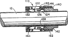
The 3rd embodiment is called non-moving type fixing device 210 as shown in Figure 5.After fixing device was fastened, the effect of non-moving type fixing device was that machine parts is remained on fixing axial position.The non-moving type fixing device has the overcoat similar to first embodiment 250, and there is internal thread 252 this overcoat rear end, and this overcoat front end also has inner conical surface.The non-moving type fixing device also has nut 240, and this nut has the outside thread 242 that is connected with overcoat 250, and this nut also has the annular outward flange 248 that is connected with interior cover 220.Similar to the interior cover among first embodiment, in the muscle 232 that is with annular inner flange 224, inner groove 226 and separates., be with one and the corresponding hole of separation bush 260 outer surfaces in the non-moving type fixing device, lining 260 is as shown in Figure 5 between interior cover and axle 12.
Lining 260 has and the corresponding cylindrical outer surface in the hole of interior cover 220, and has and axle 12 the corresponding cylindrical hole of the diameter of axle.Lining 260 also has a plurality of end slots and a groove, and fastened and from when getting loose axle and machine parts engage with convenient fixing device, interior cover can pucker ﹠ bloat.The overcoat 250 of non-moving type fixing device has support 258, and it radially inwardly stretches out the preceding end in contact with lining 260.In addition, the corresponding groove 243 of the thickness of the Kong Youyu lining 260 of nut 240, lining 260 puts in this groove.Groove 243 provides the space that holds spring 270 between nut 240 and axle 12.Spring 270 is pressed to support 258 with lining between the rear end of the rear end of nut groove 243 and lining 260.
In cover 220 with apply mechanically the mode similar outward and be connected to each other to first embodiment, and use with the similar mode of first embodiment and be connected with nut 240.During work, fastening nut 240 moves overcoat backward, so that the inner conical surface of overcoat 250 contacts with the male cone (strobilus masculinus) of interior cover 220.Along with the displacement of overcoat, work against the support 258 of lining 260 axial force is backward passed to this lining with respect to nut.The axial force that support applies is resisted mutually with the elastic force that spring 270 is pressed to separation bush.Like this, not displacement to axial between lining 260, overcoat 250 and the axle 12 of fixing device 10 during fastening fixing device.
The 4th embodiment as shown in Figure 6 and Figure 7, cover and overcoat are opposite with first embodiment in it, promptly overcoat is by the nut constrained, interior cover is connected with nut thread.Fig. 6 and embodiment illustrated in fig. 7 in, individual single-piece overcoat 350 is arranged, it has and the corresponding cylindrical outer surface in machine parts hole.The internal surface of overcoat 350 is being the conical surface near the front end place.Near the overcoat rear end, the inner flange 324 of overcoat radially inwardly stretches out and adjacent inner groove 326 is arranged.The same way as that cover 20 flanges 24 are connected with nut among overcoat 350 inner flanges 324 usefulness and first embodiment engages with nut 340.For this purpose, nut 340 has annular outward flange 348 that radially outward stretches out and adjacent outer groove 346.Nut 340 also has the internal thread 342 that is threaded with interior cover 320.
The outside thread 325 of interior cover rear end is connected with nut 340.In addition, be enclosed within helical thread portion 325 fronts in male cone (strobilus masculinus) is arranged.In the cone angle of cover 320 male cone (strobilus masculinus)s corresponding with the cone angle of overcoat 350 inner conical surfaces so that along with the relatively upwards slip or of the conical surface of two cooperations of the relative displacement between interior cover and the overcoat to lower slider.
The internal diameter of overcoat inner flange 324 is less than the external diameter of nut outward flange 348, and the overcoat flange must be by the nut flange so that make overcoat be connected with nut.Therefore, be connected with nut in order to make the single-piece overcoat, enough flexibilities must be arranged overcoat so that the protruding part of nut 340 outward flanges is crossed in the overcoat radial expansion.For this purpose, overcoat 350 is by forming a plurality of partitioning portions from overcoat rear end 351 along its axially extended groove 354 (as shown in Figure 6 and Figure 7).Except a groove, all the other grooves all stop along the front end 359 inside lines at interval with overcoat 350.The terminal of groove 352 together with groove, provides the muscle 332 of separation, and muscle 332 connects the partitioning portion of overcoat at front end 359.In the present embodiment, apply mechanically 1215 steel outward and make, have three width and be about 5/64 inch equidistant groove, wherein two is end slot 354, and another is groove 354a., will be appreciated that number, width, length and the pitch of grooves that can change groove is to reach necessary flexibility.Stop before the front end of end slot 322 cover in just arriving, and muscle 332 is the thickest at the front end place of overcoat, the thickness that muscle 332 extends towards rear end 351 directions of overcoat reduces gradually.Like this, but be enough to make the overcoat radial deformation so that overcoat is connected with nut at the axial length of front end 359 place's muscle 332.
By on nut, promoting overcoat overcoat 350 is connected with nut 340 with following mode.Make rear end 351 axial displacements of overcoat make it to engage with nut outward flange 326.When overcoat and nut engages, overcoat distortion and radially outward expansion on the nut outward flange.For ease of this radial expansion, but the ear end face chamfering of overcoat inner flange 324.Overcoat moves past nut outward flange 348 with respect to the nut back displacement until overcoat inner flange 324.Overcoat 350 elastic shrinkage then, so that the inner flange of overcoat engages with the annular groove 346 of nut, nut outward flange 348 engages with the annular groove 326 of overcoat.Like this, overcoat is clamped by nut.
In addition, the outward flange 348 of the inner flange 324 of overcoat and nut can be with stretching out round about to the reverse mode of similar interior cover shown in Figure 4 and nut flange.In other words, overcoat can have outward flange that radially outward stretches out and adjacent outer groove thereof.Connected nut has the inner flange that radially inwardly stretches out and adjacent inner groove thereof.For overcoat is connected with nut, overcoat makes the overcoat outward flange axially move past the nut inner flange to internal strain.Then, overcoat outward flange elastic expansion insert nut annular groove, the nut flange embeds the overcoat annular groove.
In the embodiment shown in fig. 7, overcoat 350 ' also have tool engagement face.In the present embodiment, the tool engagement face comprises a plurality of opposed flat clamping around the overcoat outer rim.On the other hand, overcoat 350 ' with overcoat 350 is identical, and appropriate section is represented by the reference number that adds apostrophe (').In the present embodiment, as shown in Figure 7 gripping surface be to nut 340 ' the similar hexagon of hexagon outer rim.Had gripping surface 380 just to need not for fastening and unclamp fixing device, fastening and when unclamping fixing device with the tool holder mandrel that transmits countertorque or machine parts to prevent an axle rotation.In addition, the tool engagement face can have the bearing of one or more admittance spanners.During work, a spanner or other instrument and overcoat 350 ' gripping surface 380 engage, second spanner contact nut 340 '.Being applied to two power on the spanner rotates nut and overcoat round about.For example, make fixing device throw off axle and machine parts, (in Fig. 7) rotate counterclockwise nut 340 ' and clockwise rotate overcoat 350 '.Although have only Fig. 7 to express gripping surface, to each embodiment shown in Figure 5, equally such gripping surface can be arranged at Fig. 1.
Under the situation of the serious overload of machine, the present invention is particularly conducive to the damage of avoiding axle and machine parts.The major advantage of structure of the present invention is that it skids and protects some parts of machine and can not damage above-mentioned axle or above-mentioned machine parts.Because when overload caused fixing device to skid, itself can not damage, can continue to use and need not change or readjust.Select the used material part of finished parts in the operating conditions restriction, structure of the present invention also makes fixing device make with nonmetallic material.
Cover is particularly suitable for the occasion that accurate balance is rotated in requirement together with the use of single-piece overcoat in the single-piece.Existing fixing device comprises cover or overcoat in the multi-part type, and when tightening or loosening fixing device, each part of forming the multi-part type cover can relatively move, and therefore changes the rotary balance state of fixing device.The present invention is without the multi-part type cover, and it has fixing rotary balance in fact when fixing device is worked.This shows that fixing device can be passed through circumferential balance during manufacture, and keep balance in normal work period.
Those are familiar with those of ordinary skill in the art and will appreciate that not breaking away from design that the present invention summarizes can change or retrofit the foregoing description.So, should understand the specific embodiment that the invention is not restricted to the description of this specification, and it comprises that also institute changes or retrofits in the spirit and scope of the present invention described in the following claims.
Claims (38)
1, be used for the coaxial device (10 that is installed on the axle (12) of machine parts (11), 110,210,310,310 ') comprise the overcoat (50 that engages with machine parts, 150,250,350,350 '), interior cover (20 around described axle, 120,220,320) and nut (40,140,240,340), be with inner conical surface outside described and have at least one axial groove (54) to expand to allow described overcoat along described overcoat longitudinal extension, be with the male cone (strobilus masculinus) that cooperates with described overcoat inner conical surface in described, one of them of described two covers has screw thread (52,152,252,325), wherein another of described two covers has annular interlocking portion (24,124,224,324 '), described nut has the screw thread (42 with the threaded joint of a described cover, 142,242,342) and the annular flange (48 that can be connected rotationally with the interlocking portion of described another cover, 148,248,348), wherein, when when a sense of rotation is rotated described nut, its screw thread makes a described direction that is enclosed within respect to described nut produce axial displacement, and described nut makes described another cover in the opposite direction produce axial displacement, described displacement cause described in cover be close to that cylindrical shaft shrinks and described overcoat is close to machine parts and expands, it is characterized in that:
Described another cover is single-piece cover and a plurality of axial grooves along its longitudinal extension (22,22a, 354,354a) is arranged that the structure of described groove and orientation provide enough flexibilities to cross described flange to allow interlocking portion.
2, be used for coaxial the above the device (10 of axle (12) that is installed in of machine parts (11), 110,210,310,310 ') comprise the overcoat (50 that engages with machine parts, 150,250,350), interior cover (20 around described axle, 120,220,320) and nut (40,140,240,340), be with inner conical surface outside described and have at least one axial groove (54) to expand to allow described overcoat along described overcoat longitudinal extension, be with the male cone (strobilus masculinus) that cooperates with described overcoat inner conical surface in described, one of them of described two covers has screw thread (52,152,252,325), wherein another of described two covers has annular interlocking portion (24,124,224,324 '), described nut has the screw thread that is threaded (42 with a described cover, 142,242,342) and the annular flange (48 that can be connected rotationally with the interlocking portion of described another cover, 148,248,348), wherein, when when a sense of rotation is rotated described nut, its screw thread makes a described direction that is enclosed within respect to described nut produce axial displacement, and described nut makes described another cover in the opposite direction produce axial displacement, described displacement causes described interior cover to be close to the cylindrical shaft contraction and described overcoat is close to the machine parts expansion, when rotating described nut along opposite sense of rotation, its screw thread makes on the described opposite direction that is enclosed within respect to described nut and produces axial displacement, described nut makes described another be enclosed within a direction and produces axial displacement, described displacement allow described in cover expand and leave cylindrical shaft and described overcoat shrinks and leaves machine parts, it is characterized in that:
Described another cover is single-piece cover and a plurality of axial grooves along its longitudinal extension (22,22a, 354,354a) is arranged that the structure of described groove and orientation provide enough flexibilities to cross described flange to allow interlocking portion.
3, by the described device of claim 1 (10,110,210,310,310 '), it is characterized in that: described nut (40,140,240,340) also has the annular groove (46,146,246,346 ') adjacent with described flange (48,148,248,348 '), wherein said another cover has enough flexibilities so that its distortion and allow described interlocking portion to cross after the described flange, and the annular interlocking portion (24,124,224,324 ') of described another cover engages with described annular groove.
4, by the described device of claim 2 (10,110,210,310,310 '), it is characterized in that: described nut (40,140,240,340) also has the annular groove (46,146,246,346 ') adjacent with described flange (48,148,248,348 '), wherein said another cover has enough flexibilities so that its distortion and allow described interlocking portion to cross after the described flange, and the annular interlocking portion (24,124,224,324 ') of described another cover engages with described annular groove.
5, by the described device of claim 3, it is characterized in that: described flange (148) radially inwardly stretches out, and described distortion is shunk described cover and crossed described flange, and described cover expands described annular interlocking portion is engaged with described annular groove.
6, by the described device of claim 4, it is characterized in that: described flange (148) radially inwardly stretches out, and described distortion is shunk described cover and crossed described flange, and described cover expands described annular interlocking portion is engaged with described annular groove.
7, by the described device of claim 3 (10,210,310,310 '), it is characterized in that: described flange (48,248,348) radially outward stretches out, described distortion is expanded described cover and is crossed described flange, and described cover shrinks described annular interlocking portion is engaged with described annular groove.
8, by the described device of claim 4 (10,210,310,310 '), it is characterized in that: described flange (48,248,348) radially outward stretches out, described distortion is expanded described cover and is crossed described flange, and described cover shrinks described annular interlocking portion is engaged with described annular groove.
9, by the described device of claim 3 (310 '), it is characterized in that: a described nut (340 ') and a described cover (350 ') all have tool engagement face (345,380).
10, by the described device of claim 4 (310 '), it is characterized in that: a described nut (340 ') and a described cover (350 ') all have tool engagement face (345,380).
11, by the described device of claim 9 (310 '), it is characterized in that: a described cover is an overcoat, and the described tool engagement face (380) of described overcoat is outward also near described nut.
12, by the described device of claim 10 (310 '), it is characterized in that: a described cover is an overcoat, and the described tool engagement face (380) of described overcoat is outward also near described nut.
13, by the described device of claim 3 (10,110,210), it is characterized in that: the external diameter of described overcoat is greater than the external diameter of described nut.
14, by the described device of claim 4 (10,110,210), it is characterized in that: the external diameter of described overcoat is greater than the external diameter of described nut.
15, by the described device of claim 3 (10,110,210,310,310 '), it is characterized in that: a described cover is the single-piece cover and an end is arranged that its periphery of described end is continuous.
16, by the described device of claim 4 (10,110,210,310,310 '), it is characterized in that: a described cover is the single-piece cover and an end is arranged that its periphery of described end is continuous.
17, by the described device of institute's claim 3 (10,110), it is characterized in that: described another is with chamfer surface (28,128) makes described interlocking portion cross described flange to help described cover distortion.
18, by the described device of institute's claim 4 (10,110), it is characterized in that: described another is with chamfer surface (28,128) makes described interlocking portion cross described flange to help described cover distortion.
19, by the described device of institute's claim 3 (10,110), it is characterized in that: described another is with and comprises that a plurality of segmentations and the muscle that is connected more described segmentation (32,132,232,332 ') around described another cover, described muscle have flexibility and cross described flange and joint after described flange to allow described annular interlocking portion.
20, by the described device of institute's claim 4 (10,110), it is characterized in that: described another is with and comprises that a plurality of segmentations and the muscle that is connected more described segmentation (32,132,232,332 ') around described another cover, described muscle have flexibility and cross described flange and joint after described flange to allow described annular interlocking portion.
21, by the described device of claim 19 (110,210), it is characterized in that: described nut also comprises the annular groove adjacent with described flange (46,146), and described muscle has enough elasticity so that the described annular interlocking in described cover distortion back portion engages with described annular groove.
22, by the described device of claim 20 (110,210), it is characterized in that: described nut also comprises the annular groove adjacent with described flange (46,146), and described muscle has enough elasticity so that the described annular interlocking in described cover distortion back portion engages with described annular groove.
23, by the device (10,110,210,310,310 ') described in the claim 3, it is characterized in that: when rotating described nut, the screw thread of described nut is threaded with a described cover, so that it produces axial displacement and described machine parts is fastened on the described axle along direction with respect to described another cover, the described nut of backward rotation make a described cover produce axial displacement in opposite direction in case with described machine parts from described axle disengagement.
24, by the device (10,110,210,310,310 ') described in the claim 4, it is characterized in that: when rotating described nut, the screw thread of described nut is threaded with a described cover, so that it produces axial displacement and described machine parts is fastened on the described axle along direction with respect to described another cover, the described nut of backward rotation make a described cover produce axial displacement in opposite direction in case with described machine parts from described axle disengagement.
25, by the device (10,110,210,310,310 ') described in the claim 3, it is characterized in that: the interlocking portion of described another cover has second annular flange that engages with the annular flange of described nut to throw off with described nut to prevent described interior cover.
26, by the device (10,110,210,310,310 ') described in the claim 4, it is characterized in that: the interlocking portion of described another cover has second annular flange that engages with the annular flange of described nut to throw off with described nut to prevent described interior cover.
27, by the described device of claim 25 (10,110,210), it is characterized in that: described nut flange radially outward stretches out, and the flange of described another cover radially inwardly stretches out and makes it to engage in described annular groove.
28, by the described device of claim 26 (10,110,210), it is characterized in that: described nut flange radially outward stretches out, and the flange of described another cover radially inwardly stretches out and makes it to engage in described annular groove.
29, by the described device of claim 25 (310,310 '), it is characterized in that: described nut flange radially inwardly stretches out, and the flange radially outward of described another cover stretches out and makes it to engage in described annular groove.
30, by the described device of claim 26 (310,310 '), it is characterized in that: described nut flange radially inwardly stretches out, and the flange radially outward of described another cover stretches out and makes it to engage in described annular groove.
31, by the device (210) described in described arbitrary claim, described one is with the ring-shaped bearing portion (258) of radially inwardly stretching out, described fixing device comprises around described axle and the cylindrical bush (260) between described axle and described cover, described lining is against described support, described nut has the endoporus (243) of aperture greater than the described diameter of axle, and the bias piece (270) that is arranged in described nut inner hole is pressed to described support with described lining.
32, with the described device of described arbitrary claim with the coaxial method that is installed on the axle of machine parts, comprise the steps: when described nut and described another cover are thrown off both one of them of described machine parts and described axle, to make described cover and described nut interlocking; Make described machine parts on the direction of described axle expectation and described fixing device is positioned between described axle and the described machine parts thereafter; Described nut being fastened on described one puts so that the interior cover on overcoat in the machine parts and the axle is fixed on the direction of expectation again.
33, with the coaxial method that is installed on the axle of porose machine parts, use comprises the single-piece overcoat that engages with machine parts, device around cover and nut in the single-piece of described axle, described outer be with inner conical surface and have at least one along the axial groove of described overcoat longitudinal extension so that described overcoat expand, be with the male cone (strobilus masculinus) that cooperates with described overcoat inner conical surface in described, one of them of described two covers has internal thread near the one end, wherein another of described two covers has annular interlocking portion, described nut one end has screw thread and adjusts to axial so that engage realization with a described cover, and annular flange, described annular flange engages with the annular interlocking portion of another cover rotationally, it is characterized in that:
Distortion by another cover makes described interlocking portion cross described flange described flange is engaged with described interlocking portion,
Described fixing device is positioned between described machine parts and the described axle,
Fastening described nut makes a described cover produce axial displacement with respect to described nut and described another cover along direction, this relative displacement make described in the endoporus of cover be close to that described axle shrinks and the outer surface of described overcoat is close to the hole of machine parts and expands.
34, the method that is fixed on the described machine parts on the described axle by the adjustment of claim 32 also comprises the steps
Unclamp described nut and make a described cover produce axial displacement in opposite direction with respect to described nut and described another cover, this relative displacement makes described overcoat throw off described machine parts and/or interior cover is thrown off described axle,
Fastening described nut makes described machine parts fixing again to make described machine parts relocate also on described axle.
35, the method that is fixed on the described machine parts on the described axle by the adjustment of claim 33 also comprises the steps
Unclamp described nut and make a described cover produce axial displacement in opposite direction with respect to described nut and described another cover, this relative displacement makes described overcoat throw off described machine parts and/or interior cover is thrown off described axle,
Fastening described nut makes described machine parts fixing again to make described machine parts relocate also on described axle.
36, by the method for arbitrary claim of claim 32 to 35, it is characterized in that:, rotate described nut by tool using with respect to a described cover, fastening and/or unclamp described nut.
37, press the method for arbitrary claim of claim 32 to 35, described another is enclosed near described interlocking portion place the annular chamfer face, makes described cover distortion cross described flange by the described flange of described chamfer surface axially being pressed to described nut described flange is engaged with described interlocking portion.
38, press the method for claim 36 claim, described another is enclosed near described interlocking portion place the annular chamfer face, makes described cover distortion cross described flange by the described flange of described chamfer surface axially being pressed to described nut described flange is engaged with described interlocking portion.
Applications Claiming Priority (2)
| Application Number | Priority Date | Filing Date | Title |
|---|---|---|---|
| US08/712,168 | 1996-09-11 | ||
| US08/712,168 US5695297A (en) | 1996-09-11 | 1996-09-11 | Mounting device |
Publications (2)
| Publication Number | Publication Date |
|---|---|
| CN1237231A CN1237231A (en) | 1999-12-01 |
| CN1107171C true CN1107171C (en) | 2003-04-30 |
Family
ID=24861020
Family Applications (1)
| Application Number | Title | Priority Date | Filing Date |
|---|---|---|---|
| CN97199618A Expired - Fee Related CN1107171C (en) | 1996-09-11 | 1997-08-08 | Mounting device |
Country Status (12)
| Country | Link |
|---|---|
| US (1) | US5695297A (en) |
| EP (1) | EP0925455B1 (en) |
| JP (1) | JP2001501286A (en) |
| CN (1) | CN1107171C (en) |
| AT (1) | ATE257552T1 (en) |
| AU (1) | AU3962997A (en) |
| CA (1) | CA2265437C (en) |
| DE (1) | DE69727144T2 (en) |
| ES (1) | ES2213830T3 (en) |
| HK (1) | HK1023172A1 (en) |
| TW (1) | TW393365B (en) |
| WO (1) | WO1998011353A1 (en) |
Cited By (1)
| Publication number | Priority date | Publication date | Assignee | Title |
|---|---|---|---|---|
| CN101517253B (en) * | 2006-09-29 | 2011-07-06 | Itt制造企业公司 | A device for interconnecting a first element and a second element as well as a pump comprising such a device |
Families Citing this family (53)
| Publication number | Priority date | Publication date | Assignee | Title |
|---|---|---|---|---|
| WO1998015742A1 (en) * | 1996-10-09 | 1998-04-16 | Fenner, Inc. | Mounting device |
| AU690510B3 (en) * | 1997-09-16 | 1998-04-23 | Teh-Tsung Chiu | Device for fastening a cable to a board |
| GB9724803D0 (en) * | 1997-11-24 | 1998-01-21 | Colebrand Ltd | Telescopic tubes |
| US6357958B1 (en) | 1999-12-09 | 2002-03-19 | Fenner, Inc. | Universally adjustable mounting device |
| US6382868B1 (en) * | 2000-07-25 | 2002-05-07 | Kevin Durham | Slot lock ring |
| US6866414B2 (en) * | 2001-05-22 | 2005-03-15 | Jv Northwest, Inc. | Sanitary mixing assembly for vessels and tanks |
| US6604882B2 (en) | 2001-11-01 | 2003-08-12 | Triumph Brands, Inc. | Cable joining device with breakaway nut |
| US6745909B1 (en) * | 2003-01-13 | 2004-06-08 | Hsiu-Chen Lai | Expandable upright tubes of a coat rack |
| FR2852369B1 (en) * | 2003-03-13 | 2006-01-06 | Eurocopter France | COUPLING FLANGE SYSTEM FOR HOLLOW SHAFT |
| US6957704B2 (en) * | 2003-05-14 | 2005-10-25 | Halliburton Energy Services Inc. | Limit clamp for use with casing attachments |
| US20040226132A1 (en) * | 2003-05-15 | 2004-11-18 | Deere & Company, A Delaware Corporation | Self-locking fan shaft bearing |
| US20050089364A1 (en) * | 2003-10-24 | 2005-04-28 | Geib Randall R. | Mounting device |
| US7437857B1 (en) * | 2004-02-11 | 2008-10-21 | Spectrum Products, Llc | Compression anchor |
| NL1025491C1 (en) * | 2004-02-13 | 2005-08-16 | Willem Lodewijk Dondorff | Fastening means for fastening a rod or tube and method for fastening a rod or tube. |
| US20050220534A1 (en) * | 2004-04-02 | 2005-10-06 | Ober James R | Mounting device |
| JP4763252B2 (en) * | 2004-05-13 | 2011-08-31 | 株式会社ツガミ | ROLLING DIE AND ROLLING DEVICE HAVING THE SAME |
| US7488137B2 (en) * | 2004-12-30 | 2009-02-10 | Spx Corporation | Sanitary hub assembly and method for impeller mounting on shaft |
| US20080144986A1 (en) * | 2006-09-29 | 2008-06-19 | Roman Michael Wajda | Sleeve mounting system and method |
| US20080086864A1 (en) * | 2006-09-29 | 2008-04-17 | Roman Michael Wajda | System and method for component mounting |
| US8876066B1 (en) * | 2009-12-17 | 2014-11-04 | Progressive Fastening, Inc. | Hanger with bolt closures |
| US20110268531A1 (en) * | 2010-06-10 | 2011-11-03 | Heide Denis | Segmented thread and connecting arrangement |
| US20130193281A1 (en) * | 2012-01-12 | 2013-08-01 | The Music People, Inc. | Releasable locking connector |
| US20130315665A1 (en) * | 2012-05-24 | 2013-11-28 | Fenner U.S., Inc. | Mounting device |
| GB201210894D0 (en) * | 2012-06-20 | 2012-08-01 | Goodrich Control Sys | Angular positioning arrangement |
| US9080437B2 (en) * | 2012-09-18 | 2015-07-14 | Baker Hughes Incorporated | Adjustable locking shaft-locating device |
| CN102889307A (en) * | 2012-10-19 | 2013-01-23 | 无锡市百顺机械厂 | Coupling |
| CN103790991A (en) * | 2012-11-05 | 2014-05-14 | 陆黎琴 | Contraction connection transmission sleeve |
| US9618051B2 (en) * | 2012-12-06 | 2017-04-11 | Fenner U.S., Inc. | Method and apparatus for mounting a machine element onto a shaft |
| CN103174759A (en) * | 2013-03-29 | 2013-06-26 | 黄汉文 | Taper sleeve series fastener |
| CN104842193A (en) * | 2014-02-19 | 2015-08-19 | 襄阳长源东谷实业股份有限公司 | Multistage equal deformation elastic positioning and clamping device |
| US9776669B2 (en) * | 2014-02-26 | 2017-10-03 | GM Global Technology Operations LLC | Chassis mount structure |
| CN103862077A (en) * | 2014-03-10 | 2014-06-18 | 苏州捷德瑞精密机械有限公司 | Expansion mandrel |
| AU2015228845B2 (en) * | 2014-03-11 | 2018-11-22 | Corebon Ab | Friction connecting means |
| ES2946484T3 (en) * | 2014-05-19 | 2023-07-19 | Felix L Sorkin | Plug for the anchorage of a post-tensioned anchoring system |
| CN104276444A (en) * | 2014-09-12 | 2015-01-14 | 德清县天之成纺织品有限公司 | Wire tube rack |
| CN104259985B (en) * | 2014-09-30 | 2019-05-24 | 重庆杭飞机械制造有限公司 | For processing the stationary fixture of bushing |
| CN104989737B (en) * | 2015-07-14 | 2018-03-13 | 珠海格力电器股份有限公司 | A kind of shaft coupling |
| SE539433C2 (en) * | 2015-12-11 | 2017-09-19 | Roplan Holding Ab | Holding device for applying a sealing element to a shaft, sealing device comprising such a holding device and hydrodynamic machine including such sealing device |
| US10105771B2 (en) * | 2016-03-21 | 2018-10-23 | Iscar, Ltd. | Rotary cutting tool having tool holder with conical internal thread and replaceable cutting head with straight external thread, and said tool holder |
| US10364847B2 (en) | 2016-07-20 | 2019-07-30 | Fenner U.S., Inc. | Mounting device |
| US11274776B2 (en) * | 2016-11-14 | 2022-03-15 | Kutting Uk Limited | Connector device |
| US9945427B1 (en) | 2017-04-13 | 2018-04-17 | Bionic Power Inc. | Shaft-expanding cone lock |
| US10508447B2 (en) * | 2017-04-28 | 2019-12-17 | Precision-Hayes International Inc. | Sealing cover for concrete anchor |
| CN107747598A (en) * | 2017-08-31 | 2018-03-02 | 成都瑞迪机械科技有限公司 | For the locking and connecting device between axle and hole type parts |
| WO2019059010A1 (en) * | 2017-09-20 | 2019-03-28 | パナソニックIpマネジメント株式会社 | Mounting mechanism and electric motor using same |
| CN109870077A (en) * | 2017-12-05 | 2019-06-11 | 北京自动化控制设备研究所 | A kind of servo-operated mechanism position feedback device |
| CN108942282B (en) * | 2018-08-15 | 2020-09-01 | 赣州市志海精密科技有限公司 | Frock clamp convenient to fix |
| CN110370315B (en) * | 2019-06-12 | 2022-05-20 | 邵阳学院 | Precision calibration device for joint robot |
| CA3098339A1 (en) * | 2019-11-06 | 2021-05-06 | Institut National D'optique | Repeatable precision mounting of mechanical parts |
| CN111054684A (en) * | 2019-12-10 | 2020-04-24 | 中铁隧道集团三处有限公司 | Steel bar oil removing and cleaning equipment |
| CN111335619A (en) * | 2020-04-21 | 2020-06-26 | 中信国安建工集团有限公司 | Fastener type steel pipe template support and operation method |
| CN114042944B (en) * | 2021-11-03 | 2022-07-22 | 江苏星晨高速电机有限公司 | Lathe electric spindle limiting structure |
| CN115026521A (en) * | 2022-07-04 | 2022-09-09 | 西北稀有金属材料研究院宁夏有限公司 | Beryllium rotor machining method and corresponding tool |
Citations (5)
| Publication number | Priority date | Publication date | Assignee | Title |
|---|---|---|---|---|
| US4345851A (en) * | 1978-07-10 | 1982-08-24 | Harrington Hoists | Mounting device |
| US4615640A (en) * | 1983-05-31 | 1986-10-07 | Tsubakimoto Chain Co. | Device for connecting a wheel-like body to a shaft |
| DE3835894C1 (en) * | 1988-10-21 | 1989-08-24 | Ralph 4048 Grevenbroich De Muellenberg | |
| DE8911061U1 (en) * | 1989-09-15 | 1989-10-26 | Gebrueder Sulzer Ag, Winterthur, Ch | |
| JPH05248445A (en) * | 1992-02-18 | 1993-09-24 | Tsubakimoto Emason:Kk | Tapering fastening device having torque limiter function |
Family Cites Families (16)
| Publication number | Priority date | Publication date | Assignee | Title |
|---|---|---|---|---|
| US1687777A (en) * | 1928-10-16 | Polish-rod | ||
| US738445A (en) * | 1903-01-21 | 1903-09-08 | Ernst Gustav Hoffmann | Device for securing parts to shafts. |
| CA179220A (en) * | 1916-10-20 | 1917-09-11 | Andrew Melville Mcgill | Shaft coupling |
| US1561507A (en) * | 1925-04-25 | 1925-11-17 | Clark Ed William | Pinion or pulley coupling |
| US2889161A (en) * | 1956-05-24 | 1959-06-02 | Allis Chalmers Mfg Co | Variable pitch diameter sheave |
| IN150430B (en) * | 1977-10-03 | 1982-10-02 | Royal Tool Co | |
| US4600334A (en) * | 1978-07-10 | 1986-07-15 | Fenner America Inc. | Mounting device without axial motion |
| US4202644A (en) * | 1978-07-10 | 1980-05-13 | Trantorque Corporation | Mounting device |
| US4543704A (en) * | 1978-07-10 | 1985-10-01 | Fenner America Inc. | Method for anchoring a machine element coaxially on a rotary shaft |
| US4367053A (en) * | 1978-11-06 | 1983-01-04 | Andrew Stratienko | Clamping device |
| JPS5680524A (en) * | 1979-11-30 | 1981-07-01 | Maitei:Kk | Mechanism for mounting shaft and hub |
| JPS63210418A (en) * | 1987-02-24 | 1988-09-01 | Tsubakimoto Chain Co | Fastening device for shaft and rotary body |
| ATE94621T1 (en) * | 1987-12-01 | 1993-10-15 | Vma Nc Mess Und Antriebstechni | CLAMPING DEVICE. |
| DE8816656U1 (en) * | 1988-08-06 | 1990-04-19 | Muellenberg, Ralph, 4048 Grevenbroich, De | |
| US5374135A (en) * | 1993-08-12 | 1994-12-20 | Moore Business Forms, Inc. | Mounting machine with ready transportability |
| US5474403A (en) * | 1994-03-31 | 1995-12-12 | Fenner, Inc. | Mounting device |
-
1996
- 1996-09-11 US US08/712,168 patent/US5695297A/en not_active Expired - Lifetime
-
1997
- 1997-08-08 ES ES97937007T patent/ES2213830T3/en not_active Expired - Lifetime
- 1997-08-08 AT AT97937007T patent/ATE257552T1/en not_active IP Right Cessation
- 1997-08-08 CA CA002265437A patent/CA2265437C/en not_active Expired - Fee Related
- 1997-08-08 CN CN97199618A patent/CN1107171C/en not_active Expired - Fee Related
- 1997-08-08 DE DE69727144T patent/DE69727144T2/en not_active Expired - Lifetime
- 1997-08-08 WO PCT/US1997/012924 patent/WO1998011353A1/en active IP Right Grant
- 1997-08-08 JP JP10513640A patent/JP2001501286A/en not_active Ceased
- 1997-08-08 EP EP97937007A patent/EP0925455B1/en not_active Expired - Lifetime
- 1997-08-08 AU AU39629/97A patent/AU3962997A/en not_active Abandoned
- 1997-08-15 TW TW086111772A patent/TW393365B/en not_active IP Right Cessation
-
2000
- 2000-04-05 HK HK00102085A patent/HK1023172A1/en not_active IP Right Cessation
Patent Citations (5)
| Publication number | Priority date | Publication date | Assignee | Title |
|---|---|---|---|---|
| US4345851A (en) * | 1978-07-10 | 1982-08-24 | Harrington Hoists | Mounting device |
| US4615640A (en) * | 1983-05-31 | 1986-10-07 | Tsubakimoto Chain Co. | Device for connecting a wheel-like body to a shaft |
| DE3835894C1 (en) * | 1988-10-21 | 1989-08-24 | Ralph 4048 Grevenbroich De Muellenberg | |
| DE8911061U1 (en) * | 1989-09-15 | 1989-10-26 | Gebrueder Sulzer Ag, Winterthur, Ch | |
| JPH05248445A (en) * | 1992-02-18 | 1993-09-24 | Tsubakimoto Emason:Kk | Tapering fastening device having torque limiter function |
Cited By (1)
| Publication number | Priority date | Publication date | Assignee | Title |
|---|---|---|---|---|
| CN101517253B (en) * | 2006-09-29 | 2011-07-06 | Itt制造企业公司 | A device for interconnecting a first element and a second element as well as a pump comprising such a device |
Also Published As
| Publication number | Publication date |
|---|---|
| AU3962997A (en) | 1998-04-02 |
| WO1998011353A1 (en) | 1998-03-19 |
| HK1023172A1 (en) | 2000-09-01 |
| CA2265437C (en) | 2002-08-06 |
| DE69727144T2 (en) | 2004-11-25 |
| ATE257552T1 (en) | 2004-01-15 |
| US5695297A (en) | 1997-12-09 |
| EP0925455A1 (en) | 1999-06-30 |
| CN1237231A (en) | 1999-12-01 |
| DE69727144D1 (en) | 2004-02-12 |
| EP0925455B1 (en) | 2004-01-07 |
| CA2265437A1 (en) | 1998-03-19 |
| TW393365B (en) | 2000-06-11 |
| EP0925455A4 (en) | 1999-12-08 |
| JP2001501286A (en) | 2001-01-30 |
| ES2213830T3 (en) | 2004-09-01 |
Similar Documents
| Publication | Publication Date | Title |
|---|---|---|
| CN1107171C (en) | Mounting device | |
| US4304502A (en) | Torque and thrust transmitting bushings | |
| US5474403A (en) | Mounting device | |
| US5009539A (en) | Clamping set with screw sleeve | |
| US5096327A (en) | Clamp collar assembly | |
| US4824281A (en) | Device for connecting a wheel-like body to a shaft | |
| CN1030100C (en) | Locking fastener | |
| US4615640A (en) | Device for connecting a wheel-like body to a shaft | |
| US5067847A (en) | Clamping set for transmitting torque and/or axial forces | |
| US5902066A (en) | Taper shaft lock | |
| US6050741A (en) | Tool clamping device | |
| US5269607A (en) | Bearing assembly with locking device | |
| CN1946947A (en) | Mounting device | |
| US6036372A (en) | Bearing assembly with locking collar | |
| GB2137312A (en) | A clamping device | |
| US4848953A (en) | Clamp assembly | |
| CN1218546A (en) | Cone clamping set | |
| CN112045449B (en) | Clamping device for clamping objects, in particular tools | |
| JPS5913106A (en) | Fixture for mechanical element | |
| US20050220534A1 (en) | Mounting device | |
| JPH0579846B2 (en) | ||
| GB2084293A (en) | A connecting device for shaft joints | |
| CN1498316A (en) | Shaft coupling | |
| US5188480A (en) | Coupling fixture | |
| US5228787A (en) | Bearing assembly with locking device |
Legal Events
| Date | Code | Title | Description |
|---|---|---|---|
| C06 | Publication | ||
| PB01 | Publication | ||
| C10 | Entry into substantive examination | ||
| C14 | Grant of patent or utility model | ||
| GR01 | Patent grant | ||
| REG | Reference to a national code |
Ref country code: HK Ref legal event code: GR Ref document number: 1029610 Country of ref document: HK |
|
| C17 | Cessation of patent right | ||
| CF01 | Termination of patent right due to non-payment of annual fee |
Granted publication date: 20030430 Termination date: 20130808 |