CN110672984A - Portable direct current system ground fault detection device - Google Patents
Portable direct current system ground fault detection device Download PDFInfo
- Publication number
- CN110672984A CN110672984A CN201911155639.6A CN201911155639A CN110672984A CN 110672984 A CN110672984 A CN 110672984A CN 201911155639 A CN201911155639 A CN 201911155639A CN 110672984 A CN110672984 A CN 110672984A
- Authority
- CN
- China
- Prior art keywords
- hall current
- feet
- core board
- current sensor
- display screen
- Prior art date
- Legal status (The legal status is an assumption and is not a legal conclusion. Google has not performed a legal analysis and makes no representation as to the accuracy of the status listed.)
- Pending
Links
Images


Classifications
-
- G—PHYSICS
- G01—MEASURING; TESTING
- G01R—MEASURING ELECTRIC VARIABLES; MEASURING MAGNETIC VARIABLES
- G01R31/00—Arrangements for testing electric properties; Arrangements for locating electric faults; Arrangements for electrical testing characterised by what is being tested not provided for elsewhere
- G01R31/08—Locating faults in cables, transmission lines, or networks
- G01R31/081—Locating faults in cables, transmission lines, or networks according to type of conductors
- G01R31/086—Locating faults in cables, transmission lines, or networks according to type of conductors in power transmission or distribution networks, i.e. with interconnected conductors
-
- Y—GENERAL TAGGING OF NEW TECHNOLOGICAL DEVELOPMENTS; GENERAL TAGGING OF CROSS-SECTIONAL TECHNOLOGIES SPANNING OVER SEVERAL SECTIONS OF THE IPC; TECHNICAL SUBJECTS COVERED BY FORMER USPC CROSS-REFERENCE ART COLLECTIONS [XRACs] AND DIGESTS
- Y04—INFORMATION OR COMMUNICATION TECHNOLOGIES HAVING AN IMPACT ON OTHER TECHNOLOGY AREAS
- Y04S—SYSTEMS INTEGRATING TECHNOLOGIES RELATED TO POWER NETWORK OPERATION, COMMUNICATION OR INFORMATION TECHNOLOGIES FOR IMPROVING THE ELECTRICAL POWER GENERATION, TRANSMISSION, DISTRIBUTION, MANAGEMENT OR USAGE, i.e. SMART GRIDS
- Y04S10/00—Systems supporting electrical power generation, transmission or distribution
- Y04S10/50—Systems or methods supporting the power network operation or management, involving a certain degree of interaction with the load-side end user applications
- Y04S10/52—Outage or fault management, e.g. fault detection or location
Abstract
The invention discloses a portable direct current system ground fault detection device, which solves the problems that a protection device has the risk of tripping a circuit breaker by misoperation, and the circuit fault occurs while the direct current system is grounded, so that the protection device can be rejected and the circuit breaker cannot be tripped, thereby enlarging the power failure range. The invention comprises two high-precision Hall current sensors H1 and H2, a power supply S, a display screen M and the like, the whole process does not need to open and close the air switch to determine a fault grounding point, the risk caused by opening and closing the air switch for many times is reduced, meanwhile, the time for searching the fault grounding point can be greatly reduced, the numerical value and the waveform of the acquired voltage are displayed on the display screen, and a maintainer can quickly judge whether the detected feeder line branch is grounded through the size and the waveform of the two voltages, thereby being beneficial to ensuring the reliable operation of a power grid.
Description
Technical Field
The invention relates to a feeder insulation state monitoring device of a power system, in particular to a portable direct current system ground fault detection device.
Background
The 220V direct current system is mainly used for providing power for relay protection and safety automatic devices in power plants and transformer substations and supplying energy for opening and closing control of circuit breakers. When the direct current system has a ground fault, if the ground fault is not processed in time, on one hand, the protection device has the risk of tripping the breaker by mistake, so that the load is lost; on the other hand, when the direct current system is grounded, a line fault occurs, which may cause the protection device to fail and the circuit breaker cannot be tripped, thereby expanding the power failure range.
The traditional method for searching the direct current ground fault point mainly depends on a direct current insulation monitoring device in a station, a fault main branch is read through a ground alarm signal sent by the device, a fault main branch is determined by a pull method, branch branches under the main branch are pulled one by the pull method after the fault main branch is determined until the fault branch is found, and then branch branches under the fault branch are pulled one by the pull method until the fault branch is found, so that the steps are repeated until the fault ground point is found. Due to the fact that secondary wiring is complex, a network is huge, the number of branches is multiple, only the branch circuits are pulled to be opened and closed one by adopting a pulling method to search for a ground fault point, a long time is consumed, the risk of abnormal operation of normal operation equipment exists, and safe and stable operation of a power grid is not facilitated.
Disclosure of Invention
The technical problem to be solved by the invention is as follows: on one hand, the protection device has the risk of false tripping of the circuit breaker, so that the load is lost; on the other hand, when the direct current system is grounded, a line fault occurs, which may cause the protection device to fail and the circuit breaker cannot be tripped, thereby enlarging the power failure range; the traditional method for searching the direct-current ground fault point for many times and only adopting a pull-out method to pull branch circuits one by one to open and close to search the ground fault point consumes a long time, has the risk of causing abnormal operation of normal operation equipment, and is not beneficial to the safe and stable operation of a power grid.
The invention aims to design a portable direct current system ground fault detection device, which is used for rapidly searching fault branch circuits one by one on the basis of determining a fault main branch circuit by a direct current insulation monitoring device in a station, finally searching a fault ground point, and finally determining the fault ground point by combining a circuit pulling method. The invention is realized by the following technical scheme:
a portable direct current system ground fault detection device comprises two high-precision Hall current sensors H1 and H2, pluggable adapters IC1 and IC2, electronic signal shielding wires W1 and W2, a power supply S, a display screen M, a voltage reduction chip B, an inductor L, a plurality of resistors R, a plurality of diodes D, a plurality of capacitors C and a switching socket P0, and is characterized by further comprising a singlechip core board U, wherein the singlechip core board U is connected with the display screen M through an external FPC (flexible printed circuit) interface of the singlechip core board U, the high-precision Hall current sensors H1 and the high-precision Hall current sensors H2 are connected to an I/O (input/output) port of the singlechip core board U through a pluggable adapter IC1 and IC2 and electronic signal shielding wires W1 and W2, and the power supply S supplies power to the whole fault detection device;
further, the voltages output by the output ends of the high-precision Hall current sensor H1 and the high-precision Hall current sensor H2 are simultaneously transmitted to a singlechip core board U, the singlechip core board U samples the voltages output by the high-precision Hall current sensor H1 and the high-precision Hall current sensor H2, and the numerical value and the waveform of the collected voltages are displayed on a display screen M.
Further, the number of resistors includes resistors R1 and R2;
further, the number of diodes includes resistances D1 and D2;
further, the number of capacitors includes capacitors C1, C2, and C3;
further, the singlechip core board U is an STM32F429BIT6 core board.
Further, the display screen M is a 5-inch RGB liquid crystal screen.
Further, the power supply S is a rechargeable lithium battery with the specification of a rated voltage of 24V and a capacity of 5600 mAH.
Furthermore, the high-precision Hall current sensors H1 and H2 are medium-sized CHDC-EKW series fluxgate direct-current leakage current transmitters with the specification of 24VDC of a power supply and rated output of-5V to +5V, and the rated measurement current Ipn is 0.3 times Ipn larger than the current of a detected feeder line, and the high-precision Hall current sensors H1 and H2 are of open structures.
Further, the model B of the voltage reduction chip is XL 2596S.
Further, the diodes D1 and D2 are of type 1N 5822.
Furthermore, the capacitors C1 and C3 are electrolytic capacitors with the specifications of 220uF/35V and 220uF/10V respectively.
Furthermore, the capacitor C2 is a monolithic capacitor with the specification of 0.1 uF/35V.
Further, the high-precision hall current sensor H1 and the high-precision hall current sensor H2 are respectively connected with the singlechip core board U through two pluggable adapters IC1 and IC2, and two 4 × 0.05rvvp electronic signal shielding wires W1 and W2.
Further, the resistor R1 and the resistor R2 are both 60k Ω.
Furthermore, the 3 pins of the power source S are connected to the 1 pin of the adapting socket P0, and the 4 pins of the power source S are connected to the 2 pins of the adapting socket P0 and grounded.
Furthermore, the 25 th I/O port of the core board U of the single chip microcomputer is connected to the 11 th pin of the switching socket P0, the 37 th I/O port of the core board U of the single chip microcomputer is connected to the 12 th pin of the switching socket P0, the 38 th I/O port of the core board U of the single chip microcomputer is connected to the 6 th pin of the switching socket P0, and the 51 st I/O port of the core board U of the single chip microcomputer is connected to the 7 th pin of the switching socket P0.
Furthermore, 1 pin of the switching socket P0 is connected with 4 pins and 9 pins of the switching socket P0, and 2 pins of the switching socket P0 is connected with 5 pins and 10 pins of the switching socket P0.
Further, 1 foot of high accuracy hall current sensor H1 connect 1 foot of pluggable adapter IC1, 5 feet of pluggable adapter IC1 pass through electronic signal shielded wire W1 with the switching insert 9 feet of row P0 and be connected, 2 feet of high accuracy hall current sensor H1 connect 2 feet of pluggable adapter IC1, 6 feet of pluggable adapter IC1 pass through electronic signal shielded wire W1 with the switching insert 10 feet of row P0 and be connected, 3 feet of high accuracy hall current sensor H1 connect 3 feet of pluggable adapter IC1, 7 feet of pluggable adapter IC1 pass through electronic signal shielded wire W1 and be connected with the 12 feet of switching insert row P0, 4 feet of high accuracy hall current sensor H1 connect 4 feet of pluggable adapter IC1, the 8 feet of pluggable adapter IC1 pass through the electronic signal shielding line W1 with the switching row of inserting P0 11 feet are connected, 1 foot of high accuracy Hall current sensor H2 connect 1 foot of pluggable adapter IC2, 5 feet of pluggable adapter IC2 pass through the electronic signal shielding line W2 with the switching row of inserting P0 4 feet are connected, 2 feet of high accuracy Hall current sensor H2 connect 2 feet of pluggable adapter IC2, 6 feet of pluggable adapter IC2 pass through the electronic signal shielding line W2 with the switching row of inserting P0 5 feet are connected, 3 feet of high accuracy Hall current sensor H2 connect the 3 feet of pluggable adapter IC2, 7 feet of pluggable adapter IC2 pass through the electronic signal shielding line W2 and the 6 feet of switching row of inserting P0 are connected, high accuracy hall current sensor H2's 4 feet connect pluggable adapter IC 2's 4 feet, pluggable adapter IC 2's 8 feet pass through electronic signal shielded wire W2 with switching row of inserting P0's 7 feet be connected, diode D1's 1 foot connect switching row of inserting P0's 1 foot, diode D1's 2 feet connect condenser C1's 1 foot, condenser C1's 1 foot connect condenser C2's 1 foot, condenser C1's 2 feet with condenser C2's 2 feet be connected and ground connection, condenser C2's 1 foot connect step-down chip B's 1 foot, step-down chip B's 2 feet connect inductance L's 1 foot, step-down chip B's 4 feet connect inductance L's 2 foot, step-down chip B's 5 feet ground connection, singlechip B's 3 feet ground connection and the core board of step-down chip U3V 3 And then, the 2 pins of the inductor L are connected with the 2 pins of the diode D2, the 2 pins of the inductor L are connected with the 1 pin of the capacitor C3, the 1 pin of the diode D2 and the 2 pins of the capacitor C3 are both grounded, and the 1 pin of the capacitor C3 is connected with the input end of a 5V-to-3.3V voltage reduction chip in the singlechip core board U. Singlechip core plate U be connected with display screen M through its peripheral hardware FPC interface, singlechip core plate U's 37 th I/O mouth with resistance R1's 1 foot link to each other, singlechip core plate U's 38 th I/O mouth with resistance R2's 1 foot link to each other, resistance R1 with resistance R2's 2 feet all ground connection, but 1 foot and 5 feet intercommunication of pluggable adapter IC1 and IC2 separately, 2 feet and 6 feet intercommunication, 3 feet and 7 feet intercommunication, 4 feet and 8 feet intercommunication, electronic signal shielded wire W1 and W2's shielding layer both ends all ground connection. The pin 1 of the power supply S is connected with the positive end of an external charger, and the pin 2 of the power supply S is connected with the negative end of the external charger.
After the power supply end of the high-precision Hall current sensor H is connected with working voltage, if a current I with the size within the range of the measuring range of the Hall current sensor H is introduced from a current loop of the Hall element, a current carrier deflects and generates a potential V in the direction vertical to the current and the magnetic field, and the potential V is in direct proportion to the vector sum of the currents I introduced into the current loop.
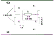
When the high-precision Hall current sensor H1 of the device is in work, the positive direction of the high-precision Hall current sensor H2 of the device is buckled on a positive feeder branch (+ KM) of the same feeder loop, and the positive feeder branch (+ KM) and the negative feeder branch (-KM) of the same feeder loop are buckled on a negative feeder branch (-KM) of the same feeder loop, so that the positive feeder branch (+ KM) and the negative feeder branch (-KM) belong to the same loop, and when the feeder is not grounded, the currents flowing through the positive feeder branch (+ KM) and the negative feeder branch (-KM) are equal in magnitude. Therefore, the voltages output by the output terminals of the high-precision hall current sensor H1 and the high-precision hall current sensor H2 are equal, when the positive pole of the feeder is grounded (as shown in fig. 12), a branch current is generated by the positive feeder branch (+ KM), the magnitudes of the currents flowing through the positive feeder branch (+ KM) and the negative feeder branch (-KM) are unequal, the voltages output by the output terminals of the high-precision hall current sensors H1 and H2 are unequal, and the current of the substation direct current system is not smooth direct current, so that the waveform of the current flowing through the ground is not identical to the waveform of the current flowing through the lead after the grounding occurs. If transmit the voltage of high accuracy hall current sensor H1 and H2 output to singlechip core board U simultaneously, sample the voltage of H1 and H2 output through singlechip core board U to on numerical value and the wave form of the voltage of will gathering all show display screen M, maintainer just can be through the size and the wave form of two voltages, judge whether the feeder branch road that detects has ground connection very fast. By adopting the above means, the branch circuit under the fault main branch circuit is searched successively, and finally the fault point can be determined.
The invention has the following advantages and beneficial effects:
whole process need not to draw and closes the sky and open and confirm the trouble ground point, has reduced the risk that the sky of drawing many times is opened and is brought, can greatly reduce the time of looking for trouble ground point simultaneously, and numerical value and the wave form of the voltage of gathering all show the display screen on, maintainer just can judge very fast whether the feeder branch road that detects has ground connection through the size and the wave form of two voltages to be favorable to guaranteeing the reliable operation of electric wire netting.
The advantages of the invention are as follows: the time for searching the fault grounding point can be greatly shortened, the risk brought to the running equipment by adopting a pull method to pull, close and open for many times is reduced, and the method has the advantages of small occupied space, convenience in carrying, simplicity in operation and high accuracy, is favorable for quickly searching the grounding fault of a direct current system, and is favorable for ensuring the reliable running of a power grid.
Drawings
The accompanying drawings, which are included to provide a further understanding of the embodiments of the invention and are incorporated in and constitute a part of this application, illustrate embodiment(s) of the invention and together with the description serve to explain the principles of the invention. In the drawings:
fig. 1 is a schematic diagram of the structure of the resistor R according to the present invention.
Fig. 2 is a schematic structural diagram of a diode D according to the present invention.
Fig. 3 is a schematic structural diagram of a capacitor C according to the present invention.
Fig. 4 is a schematic structural diagram of an inductor L according to the present invention.
FIG. 5 is a schematic structural diagram of a buck chip B according to the present invention.
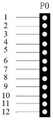
Fig. 6 is a schematic structural diagram of a patch socket P0 according to the present invention.
Fig. 7 is a schematic structural diagram of the pluggable adapter IC of the present invention.
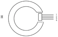
Fig. 8 is a structural diagram of a high-precision hall current sensor H according to the present invention.
Fig. 9 is a structural view of the power supply S of the present invention.
FIG. 10 is a drawing of an STM32F429BIT6 core plate of the present invention.
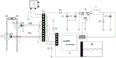
Fig. 11 is a schematic structural diagram of a portable dc system ground fault detection device according to the present invention.
Fig. 12 is a schematic diagram of the positive ground detection of a dc branch according to the present invention.
Detailed Description
Before any embodiments of the invention are explained in detail, it is to be understood that the invention is not limited in its application to the details of construction and the arrangements of components set forth in the following description or illustrated in the drawings. The invention is capable of other embodiments and of being practiced or of being carried out in various ways. All other embodiments, which can be derived by a person skilled in the art from the embodiments given herein without making any inventive changes, are within the scope of the present invention.
A portable direct current system ground fault detection device is disclosed, as shown in fig. 8, 9 and 10, and comprises two high-precision Hall current sensors H1 and H2, pluggable adapters IC1 and IC2, electronic signal shielding wires W1 and W2, a power supply S, a display screen M, a voltage reduction chip B, an inductor L, a plurality of resistors R, a plurality of diodes D, a plurality of capacitors C and a switching socket P0, and is characterized by further comprising a singlechip core board U, wherein the singlechip core board U is connected with the display screen M through an external FPC (flexible printed circuit) interface of the singlechip core board U, the high-precision Hall current sensor H1 and the high-precision Hall current sensor H2 are connected to an I/O (input/output) interface of the singlechip core board U through a pluggable adapter IC1 and IC2 and electronic signal shielding wires W1 and W2, and the power supply S (as shown in fig. 9) supplies power to the whole fault detection device;
preferably, the voltages output by the output ends of the high-precision hall current sensor H1 and the high-precision hall current sensor H2 are simultaneously transmitted to a singlechip core board U, and the singlechip core board U samples the voltages output by the high-precision hall current sensor H1 and the high-precision hall current sensor H2 and displays the values and waveforms of the collected voltages on a display screen M.
Preferably, the plurality of resistors includes resistors R1 and R2;
preferably, the plurality of diodes includes diodes D1 and D2;
preferably, the plurality of capacitors includes capacitors C1, C2, and C3;
preferably, the singlechip core board U is an STM32F429BIT6 core board.
Preferably, the display screen M is a 5-inch RGB liquid crystal screen.
Preferably, the power supply S is a rechargeable lithium battery with the specification of a rated voltage of 24V and a capacity of 5600 mAH.
Preferably, the high-precision hall current sensors H1 and H2 are medium-sized CHDC-EKW series fluxgate direct current leakage current transmitters with a power supply of 24VDC and rated output of-5V to +5V, and the rated measurement current Ipn is 0.3 times Ipn larger than the detected feeder current, and the high-precision hall current sensors H1 and H2 are of open structures.
Preferably, the high-precision hall current sensor H1 and the high-precision hall current sensor H2 are respectively connected with the singlechip core board U through two pluggable adapters IC1 and IC2 and two 4 × 0.05rvvp electronic signal shielding wires W1 and W2.
Preferably, the resistor R1 and the resistor R2 are both 60k Ω.
Preferably, the model B of the voltage reduction chip is XL 2596S.
Preferably, the diodes D1 and D2 are 1N5822 in type.
Preferably, the capacitors C1 and C3 are electrolytic capacitors with the specifications of 220uF/35V and 220uF/10V respectively.
Preferably, the capacitor C2 is a monolithic capacitor with the specification of 0.1 uF/35V.
In an embodiment of the present invention, as shown in fig. 11, 3 pins of the power source S are connected to 1 pin of the patch cord P0, and 4 pins of the power source S are connected to 2 pins of the patch cord P0 and grounded.
Preferably, the 25 th I/O port of the core board U of the one-chip microcomputer is connected to the 11 th pin of the switching socket P0, the 37 th I/O port of the core board U of the one-chip microcomputer is connected to the 12 th pin of the switching socket P0, the 38 th I/O port of the core board U of the one-chip microcomputer is connected to the 6 th pin of the switching socket P0, and the 51 st I/O port of the core board U of the one-chip microcomputer is connected to the 7 th pin of the switching socket P0.
Preferably, 1 pin of the adapting socket row P0 is connected to 4 pins and 9 pins of the adapting socket row P0, and 2 pins of the adapting socket row P0 is connected to 5 pins and 10 pins of the adapting socket row P0.
Preferably, the 1 foot of high accuracy hall current sensor H1 connect the 1 foot of pluggable adapter IC1, 5 feet of pluggable adapter IC1 pass through electronic signal shielded wire W1 with the switching insert 9 feet of row P0 and be connected, 2 feet of high accuracy hall current sensor H1 connect the 2 feet of pluggable adapter IC1, 6 feet of pluggable adapter IC1 pass through electronic signal shielded wire W1 with the switching insert 10 feet of row P0 and be connected, 3 feet of high accuracy hall current sensor H1 connect the 3 feet of pluggable adapter IC1, 7 feet of pluggable adapter IC1 pass through electronic signal shielded wire W1 and be connected with the 12 feet of switching insert row P0, 4 feet of high accuracy hall current sensor H1 connect the 4 feet of pluggable adapter IC1, the 8 feet of pluggable adapter IC1 pass through the electronic signal shielding line W1 with the switching row of inserting P0 11 feet are connected, 1 foot of high accuracy Hall current sensor H2 connect 1 foot of pluggable adapter IC2, 5 feet of pluggable adapter IC2 pass through the electronic signal shielding line W2 with the switching row of inserting P0 4 feet are connected, 2 feet of high accuracy Hall current sensor H2 connect 2 feet of pluggable adapter IC2, 6 feet of pluggable adapter IC2 pass through the electronic signal shielding line W2 with the switching row of inserting P0 5 feet are connected, 3 feet of high accuracy Hall current sensor H2 connect the 3 feet of pluggable adapter IC2, 7 feet of pluggable adapter IC2 pass through the electronic signal shielding line W2 and the 6 feet of switching row of inserting P0 are connected, high accuracy hall current sensor H2's 4 feet connect pluggable adapter IC 2's 4 feet, pluggable adapter IC 2's 8 feet pass through electronic signal shielded wire W2 with switching row of inserting P0's 7 feet be connected, diode D1's 1 foot connect switching row of inserting P0's 1 foot, diode D1's 2 feet connect condenser C1's 1 foot, condenser C1's 1 foot connect condenser C2's 1 foot, condenser C1's 2 feet with condenser C2's 2 feet be connected and ground connection, condenser C2's 1 foot connect step-down chip B's 1 foot, step-down chip B's 2 feet connect inductance L's 1 foot, step-down chip B's 4 feet connect inductance L's 2 foot, step-down chip B's 5 feet ground connection, singlechip B's 3 feet ground connection and the core board of step-down chip U3V 3 And then, the 2 pins of the inductor L are connected with the 2 pins of the diode D2, the 2 pins of the inductor L are connected with the 1 pin of the capacitor C3, the 1 pin of the diode D2 and the 2 pins of the capacitor C3 are both grounded, and the 1 pin of the capacitor C3 is connected with the input end of a 5V-to-3.3V voltage reduction chip in the singlechip core board U. Singlechip core plate U be connected with display screen M through its peripheral hardware FPC interface, singlechip core plate U's 37 th I/O mouth with resistance R1's 1 foot link to each other, singlechip core plate U's 38 th I/O mouth with resistance R2's 1 foot link to each other, resistance R1 with resistance R2's 2 feet all ground connection, but 1 foot and 5 feet intercommunication of pluggable adapter IC1 and IC2 separately, 2 feet and 6 feet intercommunication, 3 feet and 7 feet intercommunication, 4 feet and 8 feet intercommunication, electronic signal shielded wire W1 and W2's shielding layer both ends all ground connection. The pin 1 of the power supply S is connected with the positive end of an external charger, and the pin 2 of the power supply S is connected with the negative end of the external charger.
In another embodiment of the present invention, after the power supply terminal of the high-precision hall current sensor H is connected to the operating voltage, if a current I within the range of its measurement range is introduced from the current loop of the hall element, the carrier will deflect, and a potential V will be generated in the direction perpendicular to the current and the magnetic field, where the potential V is proportional to the vector sum of the currents I introduced into the current loop. The high-precision Hall current sensor H1 of the device is buckled on a positive feeder branch (+ KM) of the same feeder loop in a positive mode, the high-precision Hall current sensor H2 of the device is buckled on a negative feeder branch (-KM) of the same feeder loop in a positive mode, because the positive feeder branch (+ KM) and the negative feeder branch (-KM) belong to the same loop, when the feeder is not grounded, the currents flowing through the positive feeder branch (+ KM) and the negative feeder branch (-KM) are equal in magnitude. Therefore, the voltages output by the output terminals of the high-precision hall current sensor H1 and the high-precision hall current sensor H2 are equal, when the positive pole of the feeder is grounded (as shown in fig. 12), a branch current is generated by the positive feeder branch (+ KM), the magnitudes of the currents flowing through the positive feeder branch (+ KM) and the negative feeder branch (-KM) are unequal, the voltages output by the output terminals of the high-precision hall current sensors H1 and H2 are unequal, and the current of the substation direct current system is not smooth direct current, so that the waveform of the current flowing through the ground is not identical to the waveform of the current flowing through the lead after the grounding occurs. If transmit the voltage of high accuracy hall current sensor H1 and H2 output to singlechip core board U simultaneously, sample the voltage of H1 and H2 output through singlechip core board U to on numerical value and the wave form of the voltage of will gathering all show display screen M, maintainer just can be through the size and the wave form of two voltages, judge whether the feeder branch road that detects has ground connection very fast. By adopting the above means, the branch circuit under the fault main branch circuit is searched successively, and finally the fault point can be determined.
The above-mentioned embodiments are intended to illustrate the objects, technical solutions and advantages of the present invention in further detail, and it should be understood that the above-mentioned embodiments are merely exemplary embodiments of the present invention, and are not intended to limit the scope of the present invention, and any modifications, equivalent substitutions, improvements and the like made within the spirit and principle of the present invention should be included in the scope of the present invention.
Claims (10)
1. A portable direct current system ground fault detection device comprises two high-precision Hall current sensors H1 and H2, pluggable adapters IC1 and IC2, electronic signal shielding wires W1 and W2, a power supply S, a display screen M, a voltage reduction chip B, an inductor L, a plurality of resistors R, a plurality of diodes D, a plurality of capacitors C and a switching socket P0, and is characterized by further comprising a singlechip core board U, wherein the singlechip core board U is connected with the display screen M through an external FPC (flexible printed circuit) interface of the singlechip core board U, the high-precision Hall current sensors H1 and the high-precision Hall current sensors H2 are connected to an I/O (input/output) port of the singlechip core board U through a pluggable adapter IC1 and IC2 and electronic signal shielding wires W1 and W2, and the power supply S supplies power to the whole fault detection device;
the two high-precision Hall current sensors H1 and H2 are buckled at two ends of the same direct-current feeder line loop in the direct-current system of the transformer substation;
the voltage of high accuracy hall current sensor H1 and high accuracy hall current sensor H2 output is transmitted to singlechip core plate U simultaneously, singlechip core plate U is right the voltage of high accuracy hall current sensor H1 and high accuracy hall current sensor H2 output is sampled to all show the display screen M with numerical value and the wave form of the voltage of gathering.
2. The portable direct current system ground fault detection device of claim 1, wherein the singlechip core board U is an STM32F429BIT6 core board.
3. The apparatus of claim 1, wherein the display screen M is a 5-inch RGB liquid crystal screen.
4. The apparatus of claim 1, wherein the power source S is a rechargeable lithium battery with a rated voltage of 24V and a capacity of 5600 mAH.
5. The device as claimed in claim 1, wherein the high precision hall current sensors H1 and H2 are medium-high voltage dc-EKW series fluxgate dc leakage current transducers with a rated output of-5V to +5V and a rated measurement current Ipn 0.3 times Ipn larger than the detected feeder current, and are selected from 24VDC power supplies.
6. The apparatus of claim 1, wherein the high-precision hall current sensor H1 and the high-precision hall current sensor H2 are connected to the core board U of the single chip microcomputer via two pluggable adapters IC1 and IC2, and two 4 x 0.05rvvp electrical signal shielding wires W1 and W2, respectively.
7. The apparatus of claim 1, wherein said resistor R1 and said resistor R2 are both 60k Ω.
8. The portable direct current system ground fault detection device of claim 1, wherein the high precision hall current sensors H1 and H2 are open structures.
9. The apparatus of claim 1, wherein the capacitors C1 and C3 are electrolytic capacitors with a specification of 220uF/35V and 220uF/10V, respectively.
10. The apparatus of claim 1, wherein the capacitor C2 is a monolithic capacitor with a specification of 0.1 uF/35V.
Priority Applications (1)
| Application Number | Priority Date | Filing Date | Title |
|---|---|---|---|
| CN201911155639.6A CN110672984A (en) | 2019-11-22 | 2019-11-22 | Portable direct current system ground fault detection device |
Applications Claiming Priority (1)
| Application Number | Priority Date | Filing Date | Title |
|---|---|---|---|
| CN201911155639.6A CN110672984A (en) | 2019-11-22 | 2019-11-22 | Portable direct current system ground fault detection device |
Publications (1)
| Publication Number | Publication Date |
|---|---|
| CN110672984A true CN110672984A (en) | 2020-01-10 |
Family
ID=69088264
Family Applications (1)
| Application Number | Title | Priority Date | Filing Date |
|---|---|---|---|
| CN201911155639.6A Pending CN110672984A (en) | 2019-11-22 | 2019-11-22 | Portable direct current system ground fault detection device |
Country Status (1)
| Country | Link |
|---|---|
| CN (1) | CN110672984A (en) |
Cited By (2)
| Publication number | Priority date | Publication date | Assignee | Title |
|---|---|---|---|---|
| CN113824044A (en) * | 2021-10-29 | 2021-12-21 | 广州亿沃新能源科技有限公司 | Safety monitoring direct current ground fault protection device |
| CN114034982A (en) * | 2021-11-16 | 2022-02-11 | 国网四川省电力公司检修公司 | Floating system direct current system ground fault point positioning method and system |
Citations (9)
| Publication number | Priority date | Publication date | Assignee | Title |
|---|---|---|---|---|
| CN201130227Y (en) * | 2007-11-30 | 2008-10-08 | 上海市电力公司超高压输变电公司 | Portable DC earthing seeking instrument |
| CN101582585A (en) * | 2009-06-02 | 2009-11-18 | 河北德普电器有限公司 | Composite monitoring device for electrode difference protection and grounding of direct-current system |
| CN103472309A (en) * | 2013-09-27 | 2013-12-25 | 山东智洋电气有限公司 | Insulation monitoring device and method for DC system |
| CN203673002U (en) * | 2013-11-25 | 2014-06-25 | 国家电网公司 | Direct current system earth fault searching device |
| CN103901356A (en) * | 2014-03-18 | 2014-07-02 | 国家电网公司 | Microcomputer direct-current system fault monitoring device and method |
| CN204613374U (en) * | 2015-04-01 | 2015-09-02 | 武汉大学 | A kind of DC earthing pick-up unit of electric system and system |
| CN204759518U (en) * | 2015-05-28 | 2015-11-11 | 国网山东省电力公司经济技术研究院 | Five prevent shutting checks and accepts device |
| CN207115092U (en) * | 2017-07-13 | 2018-03-16 | 乐山师范学院 | Intelligent vehicle control circuit for students in middle and primary schools' newly manufacturing |
| CN207663964U (en) * | 2017-12-29 | 2018-07-27 | 国家电网公司 | A kind of intelligent air switch that can detect DC earthing |
-
2019
- 2019-11-22 CN CN201911155639.6A patent/CN110672984A/en active Pending
Patent Citations (9)
| Publication number | Priority date | Publication date | Assignee | Title |
|---|---|---|---|---|
| CN201130227Y (en) * | 2007-11-30 | 2008-10-08 | 上海市电力公司超高压输变电公司 | Portable DC earthing seeking instrument |
| CN101582585A (en) * | 2009-06-02 | 2009-11-18 | 河北德普电器有限公司 | Composite monitoring device for electrode difference protection and grounding of direct-current system |
| CN103472309A (en) * | 2013-09-27 | 2013-12-25 | 山东智洋电气有限公司 | Insulation monitoring device and method for DC system |
| CN203673002U (en) * | 2013-11-25 | 2014-06-25 | 国家电网公司 | Direct current system earth fault searching device |
| CN103901356A (en) * | 2014-03-18 | 2014-07-02 | 国家电网公司 | Microcomputer direct-current system fault monitoring device and method |
| CN204613374U (en) * | 2015-04-01 | 2015-09-02 | 武汉大学 | A kind of DC earthing pick-up unit of electric system and system |
| CN204759518U (en) * | 2015-05-28 | 2015-11-11 | 国网山东省电力公司经济技术研究院 | Five prevent shutting checks and accepts device |
| CN207115092U (en) * | 2017-07-13 | 2018-03-16 | 乐山师范学院 | Intelligent vehicle control circuit for students in middle and primary schools' newly manufacturing |
| CN207663964U (en) * | 2017-12-29 | 2018-07-27 | 国家电网公司 | A kind of intelligent air switch that can detect DC earthing |
Non-Patent Citations (1)
| Title |
|---|
| 刘向波: "变电站直流系统故障诊断系统开发", 《中国优秀硕士学位论文全文数据库工程科技Ⅱ辑》 * |
Cited By (3)
| Publication number | Priority date | Publication date | Assignee | Title |
|---|---|---|---|---|
| CN113824044A (en) * | 2021-10-29 | 2021-12-21 | 广州亿沃新能源科技有限公司 | Safety monitoring direct current ground fault protection device |
| CN113824044B (en) * | 2021-10-29 | 2023-01-13 | 凯铭诺(深圳)科技有限公司 | Safety monitoring direct current ground fault protection device |
| CN114034982A (en) * | 2021-11-16 | 2022-02-11 | 国网四川省电力公司检修公司 | Floating system direct current system ground fault point positioning method and system |
Similar Documents
| Publication | Publication Date | Title |
|---|---|---|
| CN101813735B (en) | Fault detection method for grounding detection device for power distribution system | |
| CN111239652A (en) | Polarity testing device for current transformer | |
| CN110672984A (en) | Portable direct current system ground fault detection device | |
| CN103163419B (en) | Indicator and method for cable core correction and transformer tripping outlet correction | |
| CN111487466A (en) | Electrified detection device for direct current resistance of secondary circuit of current transformer | |
| CN207833325U (en) | The test device and mast switch controller of mast switch controller | |
| CN201408227Y (en) | Portable 380V power system zero sequence current detection device | |
| CN211577408U (en) | Portable CT secondary side open circuit testing arrangement | |
| CN205404719U (en) | Mutual -inductor common return multipoint earthing detector | |
| CN204832398U (en) | Current transformer secondary wiring detection device that take a percentage more | |
| CN212341320U (en) | Electrified detection device for direct current resistance of secondary circuit of current transformer | |
| CN109450101A (en) | A kind of control device for low-pressure plastic shell circuit breaker | |
| CN212808479U (en) | Electrified fault diagnosis device of low-voltage transformer area zero line | |
| CN111929523B (en) | Low-voltage transformer area topology rapid identification system | |
| CN213302497U (en) | Current transformer secondary side loop detection device and circuit | |
| CN104183379A (en) | Connecting device for maintenance of secondary side of electric power current transformer | |
| CN106950511A (en) | A kind of DC power system standardized test interface arrangement | |
| CN113176438A (en) | Transformer substation secondary circuit detector and detection method | |
| CN211905644U (en) | Polarity testing device for current transformer | |
| CN215449469U (en) | Device for detecting electrical characteristics of navigation aid light isolation transformer | |
| CN211151618U (en) | Intelligent capacitance and instrument expansion system of capacitance compensation cabinet | |
| CN213813868U (en) | Circuit breaker control circuit fault point positioning device | |
| CN212321729U (en) | Current transformer secondary circuit contact resistance live detection device | |
| CN214954042U (en) | Multi-station auxiliary test bench for current transformer verification | |
| CN217718016U (en) | Miniature circuit breaker detection device |
Legal Events
| Date | Code | Title | Description |
|---|---|---|---|
| PB01 | Publication | ||
| PB01 | Publication | ||
| SE01 | Entry into force of request for substantive examination | ||
| SE01 | Entry into force of request for substantive examination | ||
| RJ01 | Rejection of invention patent application after publication | ||
| RJ01 | Rejection of invention patent application after publication |
Application publication date: 20200110 |