CN110632904A - Control method of automatic water supply system - Google Patents
Control method of automatic water supply system Download PDFInfo
- Publication number
- CN110632904A CN110632904A CN201910883168.4A CN201910883168A CN110632904A CN 110632904 A CN110632904 A CN 110632904A CN 201910883168 A CN201910883168 A CN 201910883168A CN 110632904 A CN110632904 A CN 110632904A
- Authority
- CN
- China
- Prior art keywords
- control
- monitoring
- water
- source well
- water source
- Prior art date
- Legal status (The legal status is an assumption and is not a legal conclusion. Google has not performed a legal analysis and makes no representation as to the accuracy of the status listed.)
- Pending
Links
- XLYOFNOQVPJJNP-UHFFFAOYSA-N water Substances O XLYOFNOQVPJJNP-UHFFFAOYSA-N 0.000 title claims abstract description 105
- 238000000034 method Methods 0.000 title claims abstract description 21
- 238000012544 monitoring process Methods 0.000 claims abstract description 58
- 230000001105 regulatory effect Effects 0.000 claims abstract description 42
- 238000005516 engineering process Methods 0.000 claims abstract description 6
- 230000003287 optical effect Effects 0.000 claims abstract description 6
- 239000007788 liquid Substances 0.000 claims description 30
- 238000007726 management method Methods 0.000 claims description 18
- 230000001276 controlling effect Effects 0.000 claims description 14
- 230000005540 biological transmission Effects 0.000 claims description 7
- 238000004519 manufacturing process Methods 0.000 claims description 7
- 230000008569 process Effects 0.000 claims description 4
- 238000004891 communication Methods 0.000 claims description 3
- 230000002159 abnormal effect Effects 0.000 claims description 2
- 238000001514 detection method Methods 0.000 claims description 2
- 238000007639 printing Methods 0.000 claims description 2
- 230000004044 response Effects 0.000 claims description 2
- 238000007619 statistical method Methods 0.000 claims description 2
- 238000003860 storage Methods 0.000 claims description 2
- 230000000007 visual effect Effects 0.000 claims 1
- 238000010586 diagram Methods 0.000 description 5
- 238000011161 development Methods 0.000 description 4
- 238000009826 distribution Methods 0.000 description 4
- 238000012986 modification Methods 0.000 description 3
- 230000004048 modification Effects 0.000 description 3
- 239000013307 optical fiber Substances 0.000 description 3
- 238000009530 blood pressure measurement Methods 0.000 description 2
- 230000006872 improvement Effects 0.000 description 2
- 238000007689 inspection Methods 0.000 description 2
- 238000004092 self-diagnosis Methods 0.000 description 2
- 206010063385 Intellectualisation Diseases 0.000 description 1
- 238000004458 analytical method Methods 0.000 description 1
- 238000006243 chemical reaction Methods 0.000 description 1
- 238000010276 construction Methods 0.000 description 1
- 230000007547 defect Effects 0.000 description 1
- 238000013461 design Methods 0.000 description 1
- 238000003745 diagnosis Methods 0.000 description 1
- 230000007774 longterm Effects 0.000 description 1
- 238000012423 maintenance Methods 0.000 description 1
- 238000005259 measurement Methods 0.000 description 1
- 238000012545 processing Methods 0.000 description 1
- 235000020681 well water Nutrition 0.000 description 1
- 239000002349 well water Substances 0.000 description 1
Images


Classifications
-
- G—PHYSICS
- G05—CONTROLLING; REGULATING
- G05B—CONTROL OR REGULATING SYSTEMS IN GENERAL; FUNCTIONAL ELEMENTS OF SUCH SYSTEMS; MONITORING OR TESTING ARRANGEMENTS FOR SUCH SYSTEMS OR ELEMENTS
- G05B19/00—Programme-control systems
- G05B19/02—Programme-control systems electric
- G05B19/418—Total factory control, i.e. centrally controlling a plurality of machines, e.g. direct or distributed numerical control [DNC], flexible manufacturing systems [FMS], integrated manufacturing systems [IMS], computer integrated manufacturing [CIM]
- G05B19/4183—Total factory control, i.e. centrally controlling a plurality of machines, e.g. direct or distributed numerical control [DNC], flexible manufacturing systems [FMS], integrated manufacturing systems [IMS], computer integrated manufacturing [CIM] characterised by data acquisition, e.g. workpiece identification
-
- G—PHYSICS
- G05—CONTROLLING; REGULATING
- G05B—CONTROL OR REGULATING SYSTEMS IN GENERAL; FUNCTIONAL ELEMENTS OF SUCH SYSTEMS; MONITORING OR TESTING ARRANGEMENTS FOR SUCH SYSTEMS OR ELEMENTS
- G05B19/00—Programme-control systems
- G05B19/02—Programme-control systems electric
- G05B19/418—Total factory control, i.e. centrally controlling a plurality of machines, e.g. direct or distributed numerical control [DNC], flexible manufacturing systems [FMS], integrated manufacturing systems [IMS], computer integrated manufacturing [CIM]
- G05B19/4185—Total factory control, i.e. centrally controlling a plurality of machines, e.g. direct or distributed numerical control [DNC], flexible manufacturing systems [FMS], integrated manufacturing systems [IMS], computer integrated manufacturing [CIM] characterised by the network communication
- G05B19/4186—Total factory control, i.e. centrally controlling a plurality of machines, e.g. direct or distributed numerical control [DNC], flexible manufacturing systems [FMS], integrated manufacturing systems [IMS], computer integrated manufacturing [CIM] characterised by the network communication by protocol, e.g. MAP, TOP
Abstract
The invention provides a control method of an automatic water supply system, which adopts a layered distributed control technology and comprises the following steps: the centralized automatic control system comprises a PLC field control device and an upper computer centralized management system, wherein the upper computer centralized management system, namely a master control center, is arranged in a management room; a water source well for providing a water source; the source well includes an automated monitoring system, including: each water source well is provided with an LCU control cabinet of a water source well terminal, and the control cabinet internally comprises electric primary components such as a water pump frequency converter, an air switch, a contactor, a mutual inductor and the like, and simultaneously comprises control and video equipment such as a PLC, an industrial Ethernet switch, an optical transceiver/photoelectric converter, a hard disk video recorder and the like. The system also comprises an on-site equipment monitoring terminal which is positioned in the pressure regulating valve chamber, realizes the video monitoring function of the flow regulating pressure regulating valve chamber and uploads all video monitoring data to a master control center in real time.
Description
The technical field is as follows:
the invention belongs to the field of water supply, and particularly relates to an automatic control water supply system.
Background art:
water resources have become a hot topic in the 21 st century, and water is a special and irreplaceable resource, and is a reusable and renewable resource. With the continuous progress and development of society, the problem of uneven water resource space distribution in China increasingly becomes an important restriction factor for the development of socioeconomic in China. Along with the high-rise intelligent technology progress of buildings and the rapid development of social economy, the requirements of people on the water supply quality and the reliability of a water supply system are continuously improved, and when a water source well is far away from a water user, the water supply stability is the problem which needs to be solved by a long-distance water delivery system at present.
The invention content is as follows:
the invention aims to solve the problems in the prior art, and provides a control method of an automatic water supply system according to the principle of taking the centralized monitoring of the total control as the main part and the decentralized monitoring as the auxiliary part aiming at the characteristics of a water source well and a long-distance water delivery system, which comprises the following steps:
the automatic water supply system adopts a layered distributed control technology and comprises the following steps:
the centralized automatic control system comprises a PLC field control device and an upper computer centralized management system, wherein the upper computer centralized management system, namely a master control center, is arranged in a management room;
a water source well for providing a water source; the source well includes an automated monitoring system, including: each water source well is provided with an LCU control cabinet of a water source well terminal, and the control cabinet internally comprises electric primary components such as a water pump frequency converter, an air switch, a contactor, a mutual inductor and the like, and simultaneously comprises control and video equipment such as a PLC, an industrial Ethernet switch, an optical transceiver/photoelectric converter, a hard disk video recorder and the like.
The system also comprises an on-site equipment monitoring terminal which is positioned in the pressure regulating valve chamber, realizes the video monitoring function of the flow regulating pressure regulating valve chamber, and uploads all video monitoring data to a master control center in real time
Furthermore, the control system comprises a master control center, each monitoring substation and an industrial television monitor.
Furthermore, the control signals and the industrial television monitoring signals of each pump station are all transmitted by optical fibers and wirelessly.
Furthermore, the control system has a set of complete self-diagnosis function, can automatically diagnose whether any part of the system has a fault during operation, and timely and accurately reflect fault state, fault time, fault location and related information in monitoring software; after the system is in failure, the state of the I/O should be returned to the state preset by the process requirement of the system. When alarming, the functions of voice, image display and the like can be realized.
Furthermore, the system has real-time data acquisition, processing and various display functions.
Furthermore, the start, stop and linkage operation of the equipment device can be remotely controlled by a central control room.
Has the advantages that:
the design principle of the water supply centralized control system fully reflects the reliability, the advancement, the openness, the expandability and the economy of the system, meets the requirements of equipment operation, effective acquisition monitoring, information management analysis and the like, and also considers the factors of the system in various aspects such as near and long-term development, technical updating and upgrading of products, after-sales service, transmission interfaces and the like. The system adopts distributed control, has reasonable structure and information sharing, realizes the improvement of command efficiency and achieves the purposes of reducing people and improving efficiency. The system is designed to achieve the purposes of 'no-person on site and less-person on duty in substations'. The method solves the accident hidden trouble existing in the local control, and reduces the defects that the devices are mutually disjointed and the efficiency cannot be fully exerted. The on-site unmanned operation is realized, and only equipment inspection personnel are needed. The whole system is ensured to run reliably, the failure rate is low, the maintenance is convenient and the modification is flexible. The system has flexible and reliable control function, is simple and practical, is easy to master, has friendly human-computer interface, reasonable structure and is convenient for system expansion.
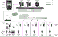
Description of the drawings:
FIG. 1 is a topological diagram of a monitoring system for a source well and a head tank.
Fig. 2 is a topological diagram of an online wireless monitoring network of a water pipeline.
Fig. 3 is a schematic view of the working principle of the water source well.
FIG. 4 is a schematic diagram of in-line detection points.
The specific implementation mode is as follows:
the technical solutions of the present invention will be described clearly and completely with reference to the accompanying drawings, and it should be understood that the described embodiments are only a part of the embodiments of the present invention, and not all of the embodiments. All other embodiments, which can be obtained by a person skilled in the art without any inventive step based on the embodiments of the present invention, belong to the scope of the present invention.
The automatic water supply system adopts a layered distributed control technology and comprises the following steps:
the centralized automatic control system comprises a PLC field control device and an upper computer centralized management system, wherein the upper computer centralized management system, namely a master control center, is arranged in a management room;
a water source well for providing a water source; the source well includes an automated monitoring system, including: each water source well is provided with an LCU control cabinet of a water source well terminal, and the control cabinet internally comprises electric primary components such as a water pump frequency converter, an air switch, a contactor, a mutual inductor and the like, and simultaneously comprises control and video equipment such as a PLC, an industrial Ethernet switch, an optical transceiver/photoelectric converter, a hard disk video recorder and the like.
The system also comprises an on-site equipment monitoring terminal which is positioned in the pressure regulating valve chamber, realizes the video monitoring function of the flow regulating pressure regulating valve chamber, and uploads all video monitoring data to a master control center in real time
The intelligent control unit is used for realizing the operation, control, monitoring and data communication of each field control device.
Furthermore, the user end can conveniently check the real-time record and the previous historical record, so that the unattended operation of the control station provides comprehensive hardware guarantee and the function of the central system is determined;
furthermore, the functions of remote control execution, timing inspection and the like can be realized;
furthermore, when abnormal conditions occur, a graded response plan is started, and the central control room gives out sound and light alarms.
Furthermore, the system of the invention adopts an open monitoring system, namely the system adopts a fully open, relational and object-oriented system structure, supports the hardware of different computer manufacturers to run in the same network, and supports a real-time multi-task and multi-user operating system. The method is mainly used for operation, monitoring and management of a centralized control system. The control system not only has reliable hardware equipment, but also has system software, application software, programming software and control software which have strong functions, reliable operation and friendly interfaces.
Furthermore, the system realizes system management, data monitoring, running state monitoring, current, theft alarm, accident alarm and equipment remote control start and stop through the configuration of the upper computer according to the basic principle that centralized monitoring is the main principle and distributed control is the auxiliary principle, and the conditions of pressure, liquid level and the like are reflected through the signals of the sensors. Managing and setting system parameters, running reports, designing and printing statistical analysis graph curves, monitoring and managing equipment, optimizing and scheduling, and reflecting the intellectualization of the system. And the control of on-site starting and stopping operation and remote starting and stopping operation of all equipment is realized. The invention monitors each device in the factory in real time in a dispatching control center, and has facilities of signal alarm, interlocking and the like to ensure the normal operation of production. The automatic control of the production process adopts independent control, namely, each substation of the equipment control layer PLC is independent from the upper monitoring computer and can independently operate without depending on the upper computer, thereby ensuring the independence and the safety of the production process.
The network part of the control system of the invention brings the electric quantity and non-electric quantity measurement and control system of the system into the monitoring background to realize uniform monitoring. The automatic system centralized monitoring network monitoring system is an important component of automatic production and management of the water source well, provides an optimized network scheme with high capacity, high speed, easy expansion, high reliability, standardization, good openness and good safety, adopts the mature network structure currently used, combines the scale of the process system of the project, requires reasonable network construction and network load distribution, and realizes the centralized monitoring of the water source well control system. The network structure uses a client/server distributed network structure and a switch technology, improves the reliability and flexibility of the network, and provides convenience for the expansion of the network connection. The provided system is easy to configure, easy to use, easy to expand, has a diagnosis function and high reliability, any subsystem in the system fails, the normal work of the whole system is not affected, and the parameters, the alarm function and the self-diagnosis function of the system can be displayed on a display screen and printed on a printer in a centralized manner.
Further, the method for automatically controlling the water source well comprises the following steps:
describing the operation condition of a water source well water pump unit:
referring to fig. 1 and 3, a topological diagram of a monitoring system of a water source well and a high-level water pool is shown in fig. 1.
The control equipment of the water source well and the high-level water tank comprises units and a water pump, wherein each unit is provided with a unit local control cabinet LCU for unit local control operation; the unit is used for controlling and driving the water pump to operate and deliver water;
the unit start and stop control is as follows: the liquid level of the water source well is used as a unit starting condition, and when the liquid level of the water source well is lower than a starting liquid level, the unit is not started; in addition, the liquid level of the water source well and the liquid level of the high-level water pool are used as criteria for stopping the pump of the unit, and when the liquid level of the water source well is lower than the liquid level of the pump, or the liquid level of the high-level water pool is higher than a set value, the unit in the water source well stops running in the running process of the unit. In addition, in order to facilitate unified monitoring management, all monitoring data signals of the water source well are uploaded to the centralized control center through the optical cable channel.
The monitoring data of the water source well comprises: the liquid level of the water source well is measured in real time by a drop-in type liquid level meter (0-100 meters);
the outlet pressure of the water pump is obtained by measuring through an intelligent pressure sensor;
the outlet flow of the water pump is obtained by measuring through an electromagnetic flowmeter;
the outlet pressure of the main pipe is obtained by measuring through an electromagnetic flowmeter;
the outlet flow of the main pipe is obtained by measuring through an electromagnetic flowmeter.
The high-level pool transmission range comprises: the liquid level of the high-level pool is measured by an intelligent radar liquid level meter;
specifically, according to one embodiment of the invention, a water source well No. 0-8# is respectively provided with a terminal local LCU control cabinet, the cabinet is started on site by adopting frequency conversion control, a PLC in the cabinet collects the running state of a water pump, monitoring the liquid level of the water well and collecting and uploading the liquid level through a 0-100 m input type liquid level meter, the PLC controls the start and stop of the water pump according to the collected liquid level, collects the current, the frequency and the water outlet pressure flow of the water pump at the same time, and power distribution data are collected and uploaded to a switch through a serial server to realize local control; the optical fiber is used for monitoring and controlling the operation of the management room master control center through the upper computer, so that the remote control is realized. Meanwhile, each water well room is provided with an intelligent infrared camera, and the monitoring images are uploaded to a management room master control center through an LCU cabinet switch. And the operation of the No. 0-8 water source well is monitored at the same time through optical fiber communication in a management room. Optionally, the 0-8# water source well, the power distribution and the image operation data are transmitted to the master control center through the 4G wireless router.
Further, the water line of the present invention is controlled as follows.
Referring to fig. 2 and 4, a topological diagram of an online wireless monitoring network of a water pipeline is shown in fig. 2.
The parameters for controlling the flow and pressure regulating chamber comprise: the opening of the flow regulating pressure regulating valve, the pressure before and after the flow regulating pressure regulating valve and the outlet flow of the flow regulating pressure regulating valve;
referring to fig. 1, a pipeline pressure measurement system detects 25 pressure measurement points along a pipeline on line; pressure data are collected and uploaded to wireless RTU equipment through an intelligent pressure sensor, and are transmitted to a master control center through a wireless transmission network, and a photovoltaic cell panel and a storage battery are used for supplying power.
Optionally, the shunt port flow regulating pressure regulating valve is provided with a control box, and an ethernet interface is configured. 1 signal isolator is additionally arranged in the PLC control box to isolate flow signals of the flowmeter to lead out 2 paths of signals, 1 path is connected into the water diversion port PLC, and the other path is connected to the flow regulating pressure regulating valve. The flow regulating and pressure regulating valve chamber PLC control box is used for monitoring the flow regulating and pressure regulating device, the inlet flow and the outlet pressure and transmitting a monitoring signal to a master control center through an RTU station by using a wireless transmission network.
The above description is only a preferred embodiment of the present invention and is not intended to limit the present invention, and various modifications and changes may be made by those skilled in the art. Any modification, equivalent replacement, or improvement made within the spirit and principle of the present invention should be included in the protection scope of the present invention.
Claims (10)
1. A control method of an automatic water supply system adopts a layered distributed control technology, and is characterized by comprising the following steps:
the centralized automatic control system comprises a PLC field control device and an upper computer centralized management system, wherein the upper computer centralized management system, namely a master control center, is arranged in a management room;
a water source well for providing a water source; the source well includes an automated monitoring system, including: each water source well is provided with an LCU control cabinet as a PLC field control device, and the control cabinet comprises a water pump frequency converter, an air switch, a contactor, a mutual inductor electrical primary component, a PLC, an industrial Ethernet switch, an optical transceiver/photoelectric converter, a hard disk video recorder and a video device;
the local equipment monitoring terminal is positioned in the pressure regulating valve chamber, realizes the functions of valve monitoring and video monitoring of the flow regulating pressure regulating valve chamber, and uploads all video monitoring data to the master control center in real time;
and the intelligent control unit realizes the detection monitoring and data communication of each pipeline monitoring point.
2. The method of controlling an automated water supply system according to claim 1, wherein:
the control equipment of the water source well and the high-level water tank comprises units and a water pump, wherein each unit is provided with a unit local control cabinet LCU for unit local control operation; the unit is used for controlling and driving the water pump to operate and deliver water.
3. The method of controlling an automated water supply system according to claim 1, wherein:
the unit start and stop control is as follows: the liquid level of the water source well is used as a unit starting condition, and when the liquid level of the water source well is lower than a starting liquid level, the unit is not started; in addition, the liquid level of the water source well and the liquid level of the high-level water pool are used as criteria for stopping the pump of the unit, and when the liquid level of the water source well is lower than the liquid level of the pump, or the liquid level of the high-level water pool is higher than a set value, the unit in the water source well stops running in the running process of the unit; and all monitoring data signals of the water source well are uploaded to the centralized control center through the optical cable channel.
4. The control method of an automated water supply system according to claim 3, wherein:
the monitoring data of the water source well comprises: the liquid level of the water source well is measured in real time by a drop-in type liquid level meter;
the outlet pressure of the water pump is obtained by measuring through an intelligent pressure sensor;
the outlet flow of the water pump is obtained by measuring through an electromagnetic flowmeter;
the outlet pressure of the main pipe is obtained by measuring through an electromagnetic flowmeter;
the outlet flow of the main pipe is obtained by measuring through an electromagnetic flowmeter.
The high-level pool transmission range comprises: the liquid level of the high-level pool is measured by an intelligent radar liquid level meter;
the parameters for controlling the flow and pressure regulating chamber comprise: the opening of the flow regulating pressure regulating valve, the pressure before and after the flow regulating pressure regulating valve and the outlet flow of the flow regulating pressure regulating valve.
5. The method of controlling an automated water supply system according to claim 1, wherein:
the pipeline pressure measuring system detects 25 pressure measuring points along the pipeline on line; pressure data are collected and uploaded to wireless RTU equipment through an intelligent pressure sensor, and are transmitted to a master control center through a wireless transmission network, and a photovoltaic cell panel and a storage battery are used for supplying power.
6. The method of controlling an automated water supply system according to claim 1, wherein:
the flow regulating and pressure regulating valve of the water diversion port is provided with a control box and is provided with an Ethernet interface; 1 signal isolator is additionally arranged in the PLC control box to isolate and lead out 2 paths of signals from a flow signal of the flowmeter, 1 path is connected to the water diversion port PLC, and the other path is connected to the flow regulating pressure regulating valve; the flow regulating and pressure regulating valve chamber PLC control box is used for monitoring the flow regulating and pressure regulating device, the inlet flow and the outlet pressure and transmitting a monitoring signal to a master control center through an RTU station by using a wireless transmission network.
7. The method of controlling an automated water supply system according to claim 1, wherein:
the user end can conveniently check the real-time record and the previous historical record, so that the unattended operation of the control station provides comprehensive hardware guarantee.
8. The method of controlling an automated water supply system according to claim 1, wherein:
the system can perform remote control, as well as timed polling.
9. The method of controlling an automated water supply system according to claim 1, wherein:
when abnormal conditions occur, a response plan with a grade is started, and the central control room gives an audible and visual alarm.
10. The method of controlling an automated water supply system according to claim 1, wherein:
system management, data monitoring, running state monitoring, current, theft alarm, accident alarm and equipment remote control start and stop are realized through the configuration of the upper computer, and the conditions of pressure and liquid level are reflected through signals of the sensors; managing and setting system parameters, running reports, designing and printing statistical analysis graph curves, monitoring and managing equipment, and optimizing scheduling; the control of on-site starting and stopping operation and remote starting and stopping operation of all equipment is realized; the dispatching control center is used for monitoring each device in the factory in real time and is provided with facilities such as signal alarm, interlocking and the like to ensure the normal operation of production; the automatic control of the production process adopts independent control, namely, each substation of the equipment control layer PLC is independent from the upper monitoring computer and does not depend on the upper computer to operate independently, so that the independence and the safety of the production process are ensured.
Priority Applications (1)
| Application Number | Priority Date | Filing Date | Title |
|---|---|---|---|
| CN201910883168.4A CN110632904A (en) | 2019-09-18 | 2019-09-18 | Control method of automatic water supply system |
Applications Claiming Priority (1)
| Application Number | Priority Date | Filing Date | Title |
|---|---|---|---|
| CN201910883168.4A CN110632904A (en) | 2019-09-18 | 2019-09-18 | Control method of automatic water supply system |
Publications (1)
| Publication Number | Publication Date |
|---|---|
| CN110632904A true CN110632904A (en) | 2019-12-31 |
Family
ID=68971357
Family Applications (1)
| Application Number | Title | Priority Date | Filing Date |
|---|---|---|---|
| CN201910883168.4A Pending CN110632904A (en) | 2019-09-18 | 2019-09-18 | Control method of automatic water supply system |
Country Status (1)
| Country | Link |
|---|---|
| CN (1) | CN110632904A (en) |
Cited By (3)
| Publication number | Priority date | Publication date | Assignee | Title |
|---|---|---|---|---|
| CN113433978A (en) * | 2021-07-01 | 2021-09-24 | 华能国际电力股份有限公司上安电厂 | Unit water supply control system optimization method |
| CN114415583A (en) * | 2021-12-24 | 2022-04-29 | 辽阳市弓长岭区瀚声矿业有限公司 | Intelligent drainage optimization control system and method for mine pump room |
| CN114637269A (en) * | 2022-04-15 | 2022-06-17 | 安徽中科大国祯信息科技有限责任公司 | Online control and scheduling system and method for water resources of smart park |
Citations (6)
| Publication number | Priority date | Publication date | Assignee | Title |
|---|---|---|---|---|
| CN2568701Y (en) * | 2002-08-31 | 2003-08-27 | 陈文宁 | Automatic switch of water pump |
| CN202149015U (en) * | 2011-07-27 | 2012-02-22 | 张明亮 | Water supply pump and high-position pool monitoring system |
| CN102393683A (en) * | 2011-07-27 | 2012-03-28 | 神华集团有限责任公司 | Method and system for controlling water level of water supply system |
| CN103711177A (en) * | 2012-10-09 | 2014-04-09 | 青岛三利中德美水设备有限公司 | Wireless based multi-well remote intelligent control water supply system |
| CN104912152A (en) * | 2015-05-29 | 2015-09-16 | 杜培文 | Safe operation scheduling system and safe operation scheduling method for water conveyance project in hilly region |
| CN208917922U (en) * | 2018-08-27 | 2019-05-31 | 赞皇金隅水泥有限公司 | A kind of water supply well water management system |
-
2019
- 2019-09-18 CN CN201910883168.4A patent/CN110632904A/en active Pending
Patent Citations (6)
| Publication number | Priority date | Publication date | Assignee | Title |
|---|---|---|---|---|
| CN2568701Y (en) * | 2002-08-31 | 2003-08-27 | 陈文宁 | Automatic switch of water pump |
| CN202149015U (en) * | 2011-07-27 | 2012-02-22 | 张明亮 | Water supply pump and high-position pool monitoring system |
| CN102393683A (en) * | 2011-07-27 | 2012-03-28 | 神华集团有限责任公司 | Method and system for controlling water level of water supply system |
| CN103711177A (en) * | 2012-10-09 | 2014-04-09 | 青岛三利中德美水设备有限公司 | Wireless based multi-well remote intelligent control water supply system |
| CN104912152A (en) * | 2015-05-29 | 2015-09-16 | 杜培文 | Safe operation scheduling system and safe operation scheduling method for water conveyance project in hilly region |
| CN208917922U (en) * | 2018-08-27 | 2019-05-31 | 赞皇金隅水泥有限公司 | A kind of water supply well water management system |
Non-Patent Citations (1)
| Title |
|---|
| 胡连森: "利用 3G 网络与 PLC构建供水调度自动化的研发应用", 《神华科技》 * |
Cited By (3)
| Publication number | Priority date | Publication date | Assignee | Title |
|---|---|---|---|---|
| CN113433978A (en) * | 2021-07-01 | 2021-09-24 | 华能国际电力股份有限公司上安电厂 | Unit water supply control system optimization method |
| CN114415583A (en) * | 2021-12-24 | 2022-04-29 | 辽阳市弓长岭区瀚声矿业有限公司 | Intelligent drainage optimization control system and method for mine pump room |
| CN114637269A (en) * | 2022-04-15 | 2022-06-17 | 安徽中科大国祯信息科技有限责任公司 | Online control and scheduling system and method for water resources of smart park |
Similar Documents
| Publication | Publication Date | Title |
|---|---|---|
| CN110632904A (en) | Control method of automatic water supply system | |
| CN104407575B (en) | A kind of railway power dispatch automated system | |
| CN102931731B (en) | Be applicable to the comprehensive intelligent supervisory control system of transforming plant DC power supply | |
| CN212304872U (en) | Intelligent power distribution monitoring and operation and maintenance system | |
| CN103092169B (en) | Digital camp apparatus management/control device | |
| CN202649799U (en) | Unmanned water supply control and management system of reservoir | |
| CN110336379A (en) | Transformer Substation Online Monitoring System and terminal device based on Internet of Things | |
| CN112306108A (en) | Remote intelligent control system for hydraulic gate | |
| CN210839646U (en) | Intelligent digital building automatic control system based on BIM technology | |
| CN202856468U (en) | Integrated intelligent monitoring system suitable for substation direct current power supply | |
| CN206162146U (en) | Intelligent case of supporting remote upgrade becomes observing and controlling system | |
| CN203455690U (en) | Intelligent transformer oil-pressure on-line monitoring device | |
| CN209979068U (en) | Dot matrix infrared cable chamber temperature measuring device based on scheduling network | |
| CN102710030B (en) | A kind of residential area power distribution room integral intelligent supervising device | |
| CN107546856A (en) | A kind of ring-main unit comprehensive monitoring system | |
| CN104617668A (en) | System and method for remotely monitoring transformer substation storage battery | |
| CN204515470U (en) | The long-range gate control system of sun power | |
| CN112664439A (en) | Secondary water supply intelligent control system | |
| CN217324058U (en) | Intelligent integrated supercharging equipment based on cloud platform technology | |
| CN109560608A (en) | A kind of intelligent managing and control system of distributed photovoltaic access power distribution network | |
| CN212647287U (en) | Water supply equipment remote monitering system | |
| CN211401300U (en) | Big data intelligent environment monitoring system | |
| CN212154859U (en) | Automatic control system for underground drainage of coal mine | |
| CN210623057U (en) | Secondary water supply intelligent control system | |
| CN210350804U (en) | Distributed energy pre-installation type complete grid-connected equipment |
Legal Events
| Date | Code | Title | Description |
|---|---|---|---|
| PB01 | Publication | ||
| PB01 | Publication | ||
| SE01 | Entry into force of request for substantive examination | ||
| SE01 | Entry into force of request for substantive examination | ||
| CB02 | Change of applicant information | ||
| CB02 | Change of applicant information |
Address after: 010050 room 1403, unit 1, Xinghe Yuyuan community, Huimin District, Hohhot City, Inner Mongolia Autonomous Region Applicant after: Inner Mongolia HUAHAN Intelligent Technology Co.,Ltd. Address before: 010000 room 1403, unit 1, Xinghe Yuyuan community, Huimin District, Hohhot City, Inner Mongolia Autonomous Region Applicant before: Inner Mongolia Qidi Technology Co.,Ltd. |
|
| RJ01 | Rejection of invention patent application after publication | ||
| RJ01 | Rejection of invention patent application after publication |
Application publication date: 20191231 |