CN1105903C - Top scale balance - Google Patents
Top scale balance Download PDFInfo
- Publication number
- CN1105903C CN1105903C CN95119118.7A CN95119118A CN1105903C CN 1105903 C CN1105903 C CN 1105903C CN 95119118 A CN95119118 A CN 95119118A CN 1105903 C CN1105903 C CN 1105903C
- Authority
- CN
- China
- Prior art keywords
- horizontal cell
- fulcrum
- elasticity
- load
- rigidity
- Prior art date
- Legal status (The legal status is an assumption and is not a legal conclusion. Google has not performed a legal analysis and makes no representation as to the accuracy of the status listed.)
- Expired - Fee Related
Links
- 210000002287 horizontal cell Anatomy 0.000 claims description 134
- 230000003068 static effect Effects 0.000 claims description 16
- 230000008093 supporting effect Effects 0.000 claims description 6
- 230000007246 mechanism Effects 0.000 description 20
- 238000006073 displacement reaction Methods 0.000 description 9
- 230000006835 compression Effects 0.000 description 8
- 238000007906 compression Methods 0.000 description 8
- 230000008859 change Effects 0.000 description 5
- 230000000694 effects Effects 0.000 description 4
- 230000001105 regulatory effect Effects 0.000 description 3
- 230000003313 weakening effect Effects 0.000 description 3
- 238000005303 weighing Methods 0.000 description 3
- 230000008878 coupling Effects 0.000 description 2
- 238000010168 coupling process Methods 0.000 description 2
- 238000005859 coupling reaction Methods 0.000 description 2
- 230000006872 improvement Effects 0.000 description 2
- 206010021703 Indifference Diseases 0.000 description 1
- 230000009471 action Effects 0.000 description 1
- 238000005452 bending Methods 0.000 description 1
- 230000015572 biosynthetic process Effects 0.000 description 1
- 238000001514 detection method Methods 0.000 description 1
- 238000010586 diagram Methods 0.000 description 1
- 230000009467 reduction Effects 0.000 description 1
- 230000035945 sensitivity Effects 0.000 description 1
- 238000006467 substitution reaction Methods 0.000 description 1
Images


Classifications
-
- G—PHYSICS
- G01—MEASURING; TESTING
- G01G—WEIGHING
- G01G21/00—Details of weighing apparatus
- G01G21/24—Guides or linkages for ensuring parallel motion of the weigh-pans
- G01G21/244—Guides or linkages for ensuring parallel motion of the weigh-pans combined with flexure-plate fulcrums
Abstract
In a top scale balance which has a Roberval's chain and a load weight transmitting lever and in which a movable post of the Roberval's chain is connected to a point of force of the lever through an elastic connection fulcrum, a horizontal member nearer to the elastic connection fulcrum, out of upper and lower horizontal members of the Roberval's chain, is greater in rigidity than the other horizontal member. Alternately, they are equal in rigidity and the elastic connection fulcrum is positioned, in the vertical direction, at the center between the upper and lower horizontal members. Such an arrangement prevents or reduces the movement of the elastic connection fulcrum in the back-and-forth direction due to an offset placed load. Thus, even though the top scale balance is made in a compact and thin design with the lever ratio increased, the top scale balance is high in precision with a less offset position error.
Description
The present invention relates to a kind of top scale balance, more specifically to a kind of top scale balance that has frame pan scale element chain (Roberual ' s chain) and be used for the leverage of transmitted load.Point out that the present invention not only can be applicable to the so-called electronic scales of the load sensing part with electromagnetic balance type, and be applicable to the so-called pan scale that has load transducer or be used as the similar device of load sensing part.
Fig. 9 (A) and (B) be the planimetric map and the side view of conventional top scale balance, Figure 10 represents its mechanism.In this top scale balance, the sample scale pan 20 utilizes frame pan scale element chain 10 (it also is called parallel guide rod) to support.This has just limited the sample scale pan 20 and has laterally moved and/or inclination, makes the sample scale pan 20 vertically move when keeping level.This error with regard to having prevented to produce owing to the skew of sample on the sample scale pan 20, promptly so-called offset position errors (it also is called as position error).
In the structure that frame pan scale element chain 10 has, movable column 13 is connected on the static column 14 by two parallel horizontal cells, these two elements are upper and lower horizontal cell 11,12, each element all is provided with flexible part 11a, 11b, 12a, 12b at its two ends, and they are as hinge portion.The sample scale pan 20 is by movable column 13 supportings.The load that acts on the sample scale pan 20 for example is delivered on the load sensing parts 40 for load transducer, electromagnetic balance mechanism and so on by being connected to lever 30 on the movable column 13.
Usually, in having the frame pan scale element chain 10 of above-mentioned configuration, the depth of parallelism between the upper and lower horizontal cell 11,12 is very important.Or rather, only under upper and lower horizontal cell 11,12 strict each other parallel conditions, just can eliminate the offset position errors of the load on the sample scale pan 20.Make that distance H, H ' among Fig. 9 (B) are strict each other equal unless promptly accurately regulate horizontal cell 11,12, otherwise will produce offset position errors.Particularly, its order of magnitude of the degree of accuracy of the generic request of the Precision Electronics Balance of electromagnetic balance type is not more than μ m.Therefore, this adjusting is not according to being undertaken by measuring distance H and H ' level in the cards.In the adjusting of reality, to finely tune the depth of parallelism between the horizontal cell 11,12, make that the measured value in each position can not change when load being applied on the sample scale pan 20 each different position.
Mechanism for the depth of parallelism that is used for adjusting bracket pan scale element chain 10 generally is well known that mechanism as shown in Figure 11.Or rather, the other end is free-ended regulating arm 71 owing to utilized an one end flexibly to be fixed to static column 14, make vertically moving of regulating arm 71 reduce to d2/d1 by rotation set screw 72, therefore make the coupling part F of horizontal cell 11 or 12 produce trickle move (for example, publication number is the Japanese Utility Model communique of 63-308522).In addition, known a kind of mechanism, wherein use a different screw as set screw 72 (publication number is the Japanese Utility Model communique of 63-35924), and a kind of mechanism, wherein by utilizing the wedge principle to make the coupling part F of a horizontal cell produce trickle moving (publication number is the Japanese Utility Model of 62-40531) and other similar means relative to static column 14.
, compare the demand of littler thinner scale along with recently, more need to increase Leveraged rate, so that utilize very little mechanism to measure big load with the scale of prior art.Yet if adopt conventional device, when it only is to increase the size that Leveraged rate reduces scale with plain mode, offset position errors becomes greatly, can not satisfy the technical requirement to scale.
Or rather, when increasing Leveraged rate, so that the distance L 1 between the application point 32 of the power of elasticity fulcrum 31 and lever 30 is shortened to about 1mm or more hour, particularly along the offset position errors of fore-and-aft direction size variation with load.Therefore, even utilize above-mentioned governor motion accurately to regulate this offset position errors, still can produce offset position errors to another load for a certain load.This has just hindered this scale to drop into actual the use.
Fig. 1 is the side view of the mechanism of explanation one embodiment, wherein first invention is applied to a kind of electronic scales of electromagnetic balance type;
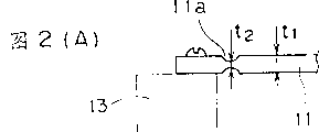
Fig. 2 is the view of explanation one particular instance configuration, wherein in embodiment shown in Fig. 1 on horizontal cell 11 than under the rigidity of horizontal cell 12 low;
Fig. 3 is the view that the operating mode that forms when time in the mechanism of loading in Fig. 1 of a placed offset is described;
Fig. 4 is the view with a kind of like this condition of geometric ways explanation, under this condition, makes in mechanism shown in Figure 1 because the amount of movement of the elasticity that the load of placed offset produces connection fulcrum 51 is 0;
Fig. 5 is the side view of the mechanism of explanation one embodiment, wherein second invention is applied to a kind of electronic scales of electromagnetic balance type;
Fig. 6 is the view of explanation operating mode of formation when the loading of a placed offset is to mechanism shown in Figure 5;
Fig. 7 is the view of the operating mode of explanation another embodiment of the present invention, the point of force application 32 that wherein elasticity is connected fulcrum 51 and lever 30 is configured to make its situation from vertical line position skew, and this vertical line is connected to each other corresponding flexible part 11a, the 12a of upper and lower horizontal cell;
Fig. 8 (A) and Fig. 8 (B) are the views of the improved customized configuration of explanation first invention;
Fig. 9 (A) and Fig. 9 (B) are the planimetric map and the side views of a general configuration with top scale balance of frame pan scale element chain and lever;
Figure 10 is the side view of the mechanism of the scale in the key diagram 9;
Figure 11 represents to utilize regulating arm to come the conventional mechanism of the depth of parallelism of adjusting bracket pan scale element chain; And
Figure 12 is the zoomed-in view of the major part of the mechanism among Figure 10, illustrates because how the position of each element of effect of the load of placed offset changes.
An object of the present invention is to provide a sharp top scale balance, it can solve the problems referred to above that conventional top scale balance exists, even wherein make the compact and slimming of mechanism design by increasing Leveraged rate, the offset position errors that produces according to the size of load changes still very little, therefore make it possible under the situation of compact to design and slimming to make the top scale balance height accurate owing to have the less deviation site error.
To achieve these goals, as shown in Figure 1, a kind of top scale balance that first invention provides comprises: a pan scale element chain 10, it has (i) upper and lower two parallel horizontal cells 11,12, each horizontal cell all is provided with flexible part at its two ends, (ii) movable column 13 and (iii) static column 14 that is connected movable column 13 by horizontal cell 11,12; One the sample scale pan 20 by movable column 13 supportings; One has the lever 30 of the application point 32 of elasticity fulcrum 31 and power, and the application point 32 of this power connects fulcrum 51 by the elasticity between upper and lower horizontal cell 11,12, is connected on the movable column 13; An and load sensing part 40, utilize lever 30 will act on loading transfer on the sample scale pan 20 on it, this top scale balance is characterised in that, for upper and lower horizontal cell 11,12, connect its rigidity of horizontal cell (horizontal cell under being) of fulcrum 51 greater than another horizontal cell (horizontal cell 11 on being) in Fig. 1 in Figure 11 near elasticity.
To achieve these goals, as shown in Figure 5, second top scale balance that provide of invention comprises: the frame pan scale element chain 10 identical and lever 30 with first invention and wherein the application point 32 of the power of lever 30 be connected fulcrum 51 by elasticity and be connected on the movable column 13, the characteristics of this top scale balance are, the rigidity of upper and lower horizontal cell 11,12 is substantially the same, and elasticity connects the center of vertical position between upper and lower horizontal cell 11,12 of fulcrum 51.
Realization of the present invention is based on following discovery, promptly find in the top scale balance of routine, offset position errors is increased, this is because because the load of placed offset causes the Leveraged rate variation, the margin of error is changed with the change of the magnitude of load of placed offset.
By adopting the setting of the first and second above-mentioned inventions, the present invention can be eliminated because the variation of the Leveraged rate that the load of placed offset causes realizes predetermined purpose whereby.
Consult Figure 10 and 12, following explanation will be discussed the device of (i) Leveraged rate each with the fact of the load change of placed offset and in (ii) inventing by employing first and second, how eliminate because the variation of the Leveraged rate that the load of placed offset causes.Figure 10 is the side view of the mechanism of a kind of top scale balance of explanation, and wherein the movable column 13 of frame pan scale element chain 10 connects the application point 32 that fulcrum 51 is connected to the power of lever 30 by elasticity, and Figure 12 is the enlarged drawing of major part among Fig. 9.
In Figure 10, when the load on the sample scale pan 20 when position a moves to position b, a tensile force affacts on the last horizontal cell 11 of frame pan scale element chain 10, and horizontal cell 11 is stretched.On the other hand, a compression force is compressed horizontal cell 12 to following horizontal cell 12.When load moved to position c, last horizontal cell 11 was compressed, and horizontal cell 12 is stretched down.
In the top scale balance of the routine of the above-mentioned type, the rigidity of upper and lower horizontal cell 11,12 is substantially the same, and the amount of tension of horizontal cell 11 or 12 is substantially equal to the decrement of horizontal cell 12 or 11.This stretching/decrement is called δ
4According to the position of the load of placed offset, as shown in figure 12, each element produces around a mid point P of straight line that connects the flexible part 12a of the flexible part 11a that goes up horizontal cell 11 and corresponding following horizontal cell 12 and moves.
Usually, when the application point 32 of power and elasticity connect distance between the fulcrum 51 when longer, then degree of accuracy is better.Correspondingly, the vertical position of elasticity connection fulcrum 51 is lower than the center between upper and lower horizontal cell 11,12.Be that A is greater than B.Therefore, when the load on acting on the sample scale pan 20 was positioned at the center of the scale pan, elasticity connected fulcrum 51 and moves from position K, and this fulcrum 51 moves to position K when load moves to position b
b, and when load moved to position c, fulcrum 51 moved to position K
c
When connecting fulcrum 51, elasticity moves to position K
bThe time, the distance L between the elasticity fulcrum 31 of the application point 32 of power and lever 30 ' less than distance L
1, and Leveraged rate is from L
1/ L
2Change to L
1'/L
2(L wherein
1' less than L
1).On the other hand, when connecting fulcrum 51, elasticity moves to position K
cThe time, L
1Increase, Leveraged rate changes to L
1"/L
2(L wherein
1" greater than L).Suppose that below the load of for example 2kg in the scope of weighing of scale moves on the sample scale pan 20.Then, governor motion action as shown in figure 11 with the depth of parallelism of adjusting bracket pan scale element chain 10, makes vertical displayed value not change.Therefore, form a kind of state, offset position errors equals 0 in this state.In this case, mean, change, make because the error that the variation of above-mentioned Leveraged rate causes is corrected by the depth of parallelism that makes frame pan scale element chain 10.So, hypothesis below, after realizing this adjusting, make have Different Weight for example the load of 4kg on the sample scale pan 20, move.In this case, the distance that moves when the load that makes 4kg equals a half of the load displacement of former 2kg, the moment of the sample scale pan 20 become equal moment 2kg load, and the tensile force and the force of compression that act on the upper and lower horizontal cell 11,12 become equal each other, and the amount of movement that k is ordered also is equal to each other.Yet, in this case, owing to load doubles, so also double owing to Leveraged rate changes the error that causes.Thereby, just not much of that for the correcting value that 2kg load is carried out for 4kg load, therefore produce error.In fact, the displacement of 4kg load equals the distance that former 2kg load moves.Therefore, the error of the load of 4kg further increases.
Why discussed above and to have become big and distance L 1 is short to about 1mm or its when following, the reason that offset position errors can increase when Leveraged rate.
In view of foregoing, the present invention can eliminate moving of the some k that causes (elasticity connects fulcrum 51) when applying the load of deviation post, prevent whereby because the variation of the Leveraged rate that the load of placed offset causes.
Or rather, adopt a kind of device according to first invention, wherein do as usual manner, this elasticity connects fulcrum 51 along with its position mobile in place towards one of them horizontal cell, and therein near the rigidity of the horizontal cell of elasticity connection fulcrum 51 greater than another horizontal cell.Thereby the extension of upper and lower horizontal cell or lower and upper horizontal cell and decrement are unequal each other, have prevented moving of some k thus.When horizontal cell 12 connects fulcrum 51 near elasticity instantly, in above-mentioned example, the rigidity of following horizontal cell 12 is higher than horizontal cell 11.In this case, as shown in Figure 3, form relational expression δ
1>δ
2, δ wherein
1Be because caused extension of going up horizontal cell 11 of the load of placed offset or decrement and δ
2Be because the load of the placed offset caused compression or the elongation of horizontal cell 12 down.Therefore, the amount of movement of some k is very little.In theory, when making δ
1And δ
2Between ratio just eliminated moving of some k when equaling ratio between A as follows and B;
δ
1/δ
2=A/B…(1)
Following explanation will prove above-mentioned relation.
As the geometric figure of representing among Fig. 4, set up following relational expression:
δ=θ(C-B)?…(2)
 ∴
∴
Wherein C is to be distance between mid point P and the following horizontal cell 11 at each center about the displacement of element, θ is an angle, promptly since the load of placed offset make connect go up horizontal cell 11 at the flexible part 11a of movable column 13 sides and following horizontal cell 12 in the straight line of the flexible part 12a of movable column 13 sides angle with respect to the vertical line inclination, and δ is an amount of movement of putting k at this moment.
Because the mobile of some k that the load of placed offset causes equals 0, the δ with in the 0 substitution equation (5) obtains following equation then in order to make:
∴δ
2A=δ
1B---(7)
Therefore, when satisfying equation (1), the mobile of k is eliminated point.
In addition, by weakening the rigidity of movable column 13 or static column 14 along continuous straight runs, connecting fulcrum 51 last horizontal cells 11 far away from elasticity can significantly reduce rigidity than following horizontal cell 12.Thereby, when owing to make the rigidity indifference of upper and lower horizontal cell 11,12 when weakening the rigidity of movable column 13 or static column 14 wittingly, the influence that is produced is equivalent to utilize and makes horizontal cell 11 itself weaken rigidity and influence that the constant devices of horizontal cell 12 itself produce.
On the other hand, adopt a kind of device according to second invention, wherein do, make the rigidity of upper and lower horizontal cell 11,12 basic identical as usual manner, and therein, the vertical position that makes elasticity connect fulcrum 51 is located at the center between the upper and lower horizontal cell 11,12.Therefore, as shown in Figure 6, because extension or decrement δ last or horizontal cell 11,12 down that the load of placed offset causes
3Equal because compression or the elongation δ following or upward horizontal cell 12,11 that the load of placed offset causes
3, and elasticity connection fulcrum 51 (some k) is positioned at because this extension or compression cause the central point of each element displacement.This has just eliminated moving of some k.
Fig. 1 is the side view of the mechanism of a preferred embodiment, wherein first invention is applied on a kind of electronic scales of electromagnetic balance type.
The basic structure that pan scale element chain 10 has is equal at the conventional structure shown in Fig. 9 and 10, wherein movable column 13 is connected on the static column 14 by upper and lower horizontal cell 11,12, each two ends place at upper and lower horizontal cell all is provided with flexible part 11a, 11b or 12a, 12b, and wherein the sample scale pan 20 by movable column 13 supportings.
As conventional scale, the load that acts on the movable column 13 is delivered on the arrangement for producing electromagnetic force 40 as the load sensing part by the lever 30 by 31 supportings of elasticity fulcrum.Or rather, the application point 32 that is configured in the power on the end of lever 30 utilizes web member 50 to connect fulcrum 51 by elasticity to be connected on the movable column 13.With the power magnetic test coil 42 of arrangement for producing electromagnetic force 40 be fixed on the lever 30 with respect to elasticity fulcrum 31 on the side opposite with the application point 32 of power.In this arrangement for producing electromagnetic force 40, the power magnetic test coil 42 that is fixed on the lever 30 is in the static magnetic field that is produced by a magnetic circuit 41 that mainly comprises permanent magnet 41a with movable manner.The displacement of lever 30 utilizes a displacement transducer 34 that is used for detecting in the position of the otch of lever 30 other ends to detect.The electric current that flows in the control magnetic test coil 42 makes the result of displacement detecting be always 0.The load of size detection on the sample scale pan 20 according to this electric current.
The vertical position that elasticity connects fulcrum 51 is compared the more following horizontal cell 12 near frame pan scale element chain 10 with last horizontal cell 11.Be A greater than B, wherein A goes up horizontal cell 11 and elasticity to connect vertical distance between the fulcrum 51, B is that horizontal cell 12 and elasticity connect vertical distance between the fulcrum 51 down.
The rigidity of following horizontal cell 12 is higher than horizontal cell 11.Or rather, shown in Fig. 2 (A), last horizontal cell 11 is in the thickness t of main part
1Less than following horizontal cell 12, perhaps go up the thickness t of horizontal cell 11 in each flexible part
2Less than following horizontal cell 12.In addition, last horizontal cell 11 is narrower than horizontal cell 12 down at the width of main part.
On the contrary, upper and lower horizontal cell 11,12 is done to such an extent that make its thickness t
1And t
2Be equal to each other, simultaneously, otch S only is formed on the horizontal cell 11 so that form elastic part E as Fig. 2 (B) shown in, this figure be on the partial plan layout of horizontal cell 11.
In addition, each the width W among flexible part 11a, the 11b of last horizontal cell 11 is done less than each the width (seeing Fig. 2 (B)) among flexible part 12a, the 12b of horizontal cell 12 down.
Regulate the ratio of rigidity of 11,12 of upper and lower horizontal cells, make
δ
1/ δ
2 A/B ... (8) δ wherein
1Be because the extension/decrement of the last horizontal cell 11 that the load of placed offset causes, δ
2Be because the compression/elongation of the following horizontal cell 12 that the load of placed offset causes.
In the above-described embodiments, hypothesis satisfies equation (8) below.As shown in Figure 3, even because the load of placed offset causes upper and lower horizontal cell 11,12 extensions or compression, elasticity connects fulcrum 51 and also is difficult to move.Therefore, even Leveraged rate increased and make distance between the point of force application 32 of elasticity fulcrum 31 and lever 30 be reduced to about 1mm or below it, the load of placed offset can not increase yet.
Following explanation will be discussed the device of second invention, and it also can be applicable to the situation of electromagnetic balance type electronic scales.Fig. 5 is the side view of the mechanism of explanation second invention.
In this embodiment, about the basic structure of the mechanism of frame pan scale element chain 10 and lever 30 and load sensing part 40 and so on respectively with the foregoing description in identical.Therefore, utilize the same reference numerals of in Fig. 1, using to mark identical part, and omit explanation them.
Embodiment is characterised in that shown in Fig. 5, and the rigidity of the upper and lower horizontal cell 11,12 of frame pan scale element chain 10 is substantially the same, and the vertical position of elasticity connection fulcrum 51 is located at the center of the distance H between the upper and lower horizontal cell 11,12.
According to the setting among Fig. 5,, be called δ below this amount because the extension and the decrement of the upper and lower horizontal cell 11,12 that the load of placed offset causes be equal to each other
3As shown in Figure 6, because this extension/decrement δ
3, elasticity connects fulcrum 51 and is difficult to move.
In each above-mentioned embodiment, the application point 32 that elasticity connects the power of fulcrum 51 and lever 30 all is positioned on the perpendicular line, and this straight line is connected to each other flexible part 11a, the 12a of the correspondence of upper and lower horizontal cell 11,12.From the mutual relationship of position, this configuration is desirable.Yet the present invention always need not dispose in above-mentioned mode.In fact, as shown in Figure 7, can be on application point 32 positions of elasticity connection fulcrum 51 and power from upper and lower flexible part 11a, the 12a perpendicular line connected to one another of correspondence is removed ε.Or rather, have weigh same a series of various types of pan scale/scales of scope of difference in order to prepare, the manufacturer of each pan scale/scale is usually according to respectively weighing scope and the pan scale/scale with various Leveraged rate being provided respectively.Therefore, in all types of pan scale/scales each, it is difficult using above-mentioned ideal position relation.Thereby, more preferably consider to select a kind of like this position relation, so that reach the resolution of the expection of the range/sensitivity of weighing, this is the most difficult performance that will realize.
Hypothesis adopts position relation as shown in Figure 7 below.When because the load of placed offset when causing upper and lower horizontal cell 11,12 extensions/compressions, the vertical mobile γ of some k at elasticity connection place, fulcrum 51 position.Yet,, only have movable column 13 vertically to move because the electromagnetic force effect that is produced by arrangement for producing electromagnetic force 40 makes lever 30 maintain constant attitude.Vertical when mobile when movable column 13, the upper and lower horizontal cell 11,12 of frame pan scale element chain 10 makes that according to identical angle tilt the depth of parallelism between the horizontal cell 11,12 does not go beyond the scope.In addition, the degree of tilt of the restoring force of flexible part 11a, the 11b of frame pan scale element chain 10,12a, 12b and horizontal cell 11,12 is proportional and not too be subjected to the influence of load capacity.In a word, according to the vertical amount of movement (increasing in proportion with the opplied moment on the sample scale pan 20) of movable column 13, the depth of parallelism that can adjusting bracket pan scale element chain 10 makes error be bordering on 0.Above-mentioned part can also be applied among each embodiment shown in Fig. 1 and Fig. 5.In addition, guarantee in the scope of ε≤about 3mm, can not encounter problems.
It is naturally important that the extension/decrement δ of the upper and lower horizontal cell 11,12 of frame pan scale element chain 10 in the above-described embodiments
1, δ
2, δ
3Must not only comprise the extension/decrement of upper and lower horizontal cell 11,12 itself, but also comprise the bending of flexible part 11a, 11b, 12a, 12b.Thereby the rigidity of upper and lower horizontal cell 11,12 also comprises the rigidity of flexible part 11a, 11b, 12a, 12b.
A kind of improvement as first invention, wherein make the rigidity between upper and lower horizontal cell 11,12 that difference is arranged, can reduce the rigidity of movable or static column 13 or 14, make the rigidity that connects fulcrum 51 horizontal cell far away apart from elasticity, the rigidity of the last horizontal cell 11 in promptly embodiment illustrated in fig. 1 is significantly smaller than down the rigidity of horizontal cell 12.The work effect that this improvement can produce is equal to the effect of utilizing Fig. 1 and 2 shown device to produce.First invention also comprises this device.
Fig. 8 (A) and 8 (B) have represented the configuration of a particular instance, wherein by weakening the rigidity of movable column 13, compare with following horizontal cell 12, and the rigidity of last horizontal cell 11 is significantly weakened.
In Fig. 8 (A), the part place of horizontal cell 11 formed an otch 13a vertically on the vicinity in movable column 13 was fixing.This has just weakened the rigidity of the movable column 13 of along continuous straight runs.
In Fig. 8 (B), near the part of the movable column 13 of fixing horizontal cell 11 and following horizontal cell 12 respectively, the movable column 13 at this place is thinner.In this case, form relational expression L
1<L
2This has also weakened the rigidity of movable column 13 along continuous straight runs.
Should admit, for the rigidity that weakens movable column 13 or static column 14 also has the other structure.For example, constitute in elongated mode partly or integrally, can eliminate moving of a k by making movable column 13 or static column 14.
In the device of first invention shown in Figure 1, make the position of lever 30 nearer from following horizontal cell 12 from last horizontal cell 11 ratios.Yet, also can make the more approaching horizontal cell 12 down in lever 30 present positions.In this set,, the application point 32 of power is connected to the preferably relatively approaching last horizontal cell 11 in elasticity connection fulcrum 51 residing positions of movable column 13 by fulcrum 51 according to the requirement of degree of accuracy.Thereby, compare with following horizontal cell 12, need to increase the rigidity that goes up horizontal cell 11.Certainly, first invention also can comprise such setting.
In addition, in each above-mentioned embodiment, all be to apply the present invention to utilize the electromagnetic balance type electronic scales of arrangement for producing electromagnetic force 40 as the load sensing part.Certainly, the present invention also can be applied to have the electronic scales of the load sensing part of other types such as load sensing device for example.
Claims (5)
1. top scale balance, comprise a pan scale element chain, this element chain has (i) upper and lower two parallel horizontal cells, be provided with flexible part at the two ends of each element, the (ii) (iii) static column of a movable column, it is connected on the described movable column by described two horizontal cells; One the sample scale pan by described movable column supporting; One has the leverage of the application point of elasticity fulcrum and power, and the application point of described power is connected on the described movable column by the elasticity connection fulcrum that is located between the described upper and lower horizontal cell; And a load sensing part, utilize described leverage to make in the loading transfer on the described sample scale pan on this load sensing part,
Described top scale balance is characterised in that the rigidity of the described horizontal cell of one of them approaching described elasticity connection fulcrum is greater than the rigidity of another horizontal cell, and the ratio of rigidity of above-mentioned two horizontal cells should satisfy the condition of following formula:
δ
1/δ
2A/B
Wherein, δ
1Be because the extension/decrement of above-mentioned another horizontal cell that the load of placed offset causes, δ
2It is the above-mentioned extension/decrement that connects the horizontal cell of fulcrum that how to cause owing to carrying of placed offset near elasticity, and A is the vertical distance between above-mentioned another horizontal cell and the elasticity connection fulcrum, and B then is above-mentioned near the horizontal cell of elasticity connection fulcrum and the vertical distance between this elasticity connection fulcrum.
2. top scale balance as claimed in claim 1 is characterized in that, the thickness of the main part of the horizontal cell of described approaching described elasticity connection fulcrum is greater than this thickness of described another horizontal cell.
3. top scale balance as claimed in claim 1 is characterized in that, the described horizontal cell near described elasticity connection fulcrum is bigger than this thickness of described another horizontal cell at the thickness of each elastic part at its two ends.
4. top scale balance as claimed in claim 1 is characterized in that, the width of the horizontal cell of described approaching described elasticity connection fulcrum is bigger than described another horizontal cell width.
5. to require 1 described top scale balance as right, it is characterized in that,
The thickness of the main part of described upper and lower horizontal cell and identical at the thickness of each flexible part at its two ends, and
Only, make that described horizontal cell is flexible in described elasticity connection fulcrum horizontal cell far away, forming a kerf.
Applications Claiming Priority (3)
| Application Number | Priority Date | Filing Date | Title |
|---|---|---|---|
| JP241119/94 | 1994-10-05 | ||
| JP241119/1994 | 1994-10-05 | ||
| JP24111994 | 1994-10-05 |
Publications (2)
| Publication Number | Publication Date |
|---|---|
| CN1130756A CN1130756A (en) | 1996-09-11 |
| CN1105903C true CN1105903C (en) | 2003-04-16 |
Family
ID=17069573
Family Applications (1)
| Application Number | Title | Priority Date | Filing Date |
|---|---|---|---|
| CN95119118.7A Expired - Fee Related CN1105903C (en) | 1994-10-05 | 1995-10-04 | Top scale balance |
Country Status (5)
| Country | Link |
|---|---|
| US (1) | US5962818A (en) |
| EP (1) | EP0706035B1 (en) |
| CN (1) | CN1105903C (en) |
| DE (1) | DE69516965T2 (en) |
| TW (1) | TW287229B (en) |
Families Citing this family (12)
| Publication number | Priority date | Publication date | Assignee | Title |
|---|---|---|---|---|
| DE19729623B4 (en) * | 1997-07-10 | 2004-10-07 | Mettler-Toledo Gmbh | Arrangement for fastening a parallelogram guide in a force measuring device |
| US6472618B1 (en) * | 1999-03-30 | 2002-10-29 | A&D Co., Ltd. | Electronic weighing scale using general purpose block member |
| DE10326699B3 (en) * | 2003-06-13 | 2005-01-13 | Sartorius Ag | Compact weighing system |
| DE202004011793U1 (en) * | 2004-07-27 | 2005-09-01 | Sartorius Ag | Weighing system according to the principle of electromagnetic force compensation |
| JP4942390B2 (en) | 2006-05-02 | 2012-05-30 | 株式会社エー・アンド・デイ | Electronic balance load measurement mechanism |
| EP1898193B1 (en) * | 2006-09-05 | 2016-06-01 | Mettler-Toledo GmbH | Force measuring device and reference unit |
| DE202008008459U1 (en) * | 2008-06-24 | 2008-08-21 | Sartorius Ag | Weighing system with transmission lever |
| PL2607866T3 (en) * | 2011-12-22 | 2015-05-29 | Mettler Toledo Gmbh | Weighing cell operating on the principle of electromagnetic force compensation with optoelectronic position sensor |
| EP2610596B2 (en) * | 2011-12-30 | 2022-03-30 | WIPOTEC GmbH | Bridging element for a scale |
| EP2634543A1 (en) | 2012-02-29 | 2013-09-04 | Mettler-Toledo AG | Weighing cell operating on the principle of magnetic power compensation with optoelectronic position sensor |
| CN105118358B (en) * | 2015-09-20 | 2018-11-27 | 天津大学 | Precision balance balance-enlarger with motion mathematical model |
| DE102019135732B4 (en) * | 2019-12-23 | 2021-09-23 | Neura Robotics GmbH | Device for measuring a change in length |
Family Cites Families (12)
| Publication number | Priority date | Publication date | Assignee | Title |
|---|---|---|---|---|
| GB1377738A (en) * | 1971-07-31 | 1974-12-18 | Avery Ltd W T | Force measuring devices |
| CH625617A5 (en) * | 1978-03-08 | 1981-09-30 | Mettler Instrumente Ag | |
| JPS57111419A (en) * | 1980-12-29 | 1982-07-10 | Shimadzu Corp | Electronic even balance |
| US4485881A (en) * | 1983-09-09 | 1984-12-04 | Pitney Bowes Inc. | Shift adjustment for a load cell |
| DE3505070A1 (en) * | 1985-02-14 | 1986-08-14 | Sartorius GmbH, 3400 Göttingen | UPPER-SHELL ELECTRONIC SCALE WITH A HANDLEBAR PARALLEL GUIDE |
| CH669043A5 (en) | 1985-08-23 | 1989-02-15 | Mettler Instrumente Ag | PRECISION SCALE. |
| CH670704A5 (en) | 1986-08-22 | 1989-06-30 | Mettler Instrumente Ag | Precision balance with supported weighing dish |
| DE3710997C1 (en) * | 1987-04-01 | 1988-05-26 | Sartorius Gmbh | Upper pan electronic scale with corner load adjustment |
| US4799561A (en) * | 1987-05-09 | 1989-01-24 | Shimadzu Corporation | Electronic balance |
| JPH02150537U (en) * | 1989-05-24 | 1990-12-26 | ||
| DE4119734A1 (en) * | 1991-06-14 | 1992-12-17 | Mettler Toledo Ag | DEVICE FOR REDUCING FORCE IN A FORCE MEASURING DEVICE, IN PARTICULAR A SCALE |
| JPH05302844A (en) * | 1992-04-27 | 1993-11-16 | Shimadzu Corp | Electronic balance |
-
1995
- 1995-09-27 TW TW084110091A patent/TW287229B/zh active
- 1995-10-03 US US08/538,776 patent/US5962818A/en not_active Expired - Fee Related
- 1995-10-04 DE DE69516965T patent/DE69516965T2/en not_active Expired - Lifetime
- 1995-10-04 CN CN95119118.7A patent/CN1105903C/en not_active Expired - Fee Related
- 1995-10-04 EP EP95307061A patent/EP0706035B1/en not_active Expired - Lifetime
Also Published As
| Publication number | Publication date |
|---|---|
| EP0706035A2 (en) | 1996-04-10 |
| EP0706035A3 (en) | 1996-07-03 |
| US5962818A (en) | 1999-10-05 |
| DE69516965D1 (en) | 2000-06-21 |
| DE69516965T2 (en) | 2000-11-09 |
| TW287229B (en) | 1996-10-01 |
| CN1130756A (en) | 1996-09-11 |
| EP0706035B1 (en) | 2000-05-17 |
Similar Documents
| Publication | Publication Date | Title |
|---|---|---|
| CN1054432C (en) | Load cell | |
| CN1105903C (en) | Top scale balance | |
| US4300648A (en) | Mass and force meter | |
| CN1077025A (en) | Electronic force sensing load cell | |
| CN85108400A (en) | Multi-range load cell weighing instrument | |
| US7851713B2 (en) | Adjustable parallel-guiding mechanism, specifically for a gravimetric measuring instrument | |
| US8100016B2 (en) | Vibratory sensor | |
| CN101216363A (en) | Torductor calibration equipment | |
| WO1995025262A1 (en) | Thin load cell having unitary structure | |
| CN1113223C (en) | Self-supporting weight sensor and scale incorporating sensors of this kind | |
| SE433884B (en) | LOAD TRANSMISSION TYPE CONVERTER WITH A PARALLEL LOGO | |
| JPH0676840U (en) | Force measuring device | |
| US9297689B2 (en) | Device and method for the adjustment of an eccentric load error in a parallel-guiding mechanism | |
| CN1162688C (en) | Electronic scales | |
| CN100344944C (en) | Weight measuring device | |
| KR100388940B1 (en) | Electric sacle capable of compensating error caused by an eccentricity of a load to be gauged and a tilt thereof | |
| US4501160A (en) | Force transducer | |
| SU1336953A3 (en) | Weight measuring device | |
| CN211234647U (en) | Five-column type weighing sensor | |
| US3248936A (en) | Temperature compensated transducer | |
| US4284155A (en) | Device for supporting the load or a load carrier in an electromechanical scale | |
| CN111412967B (en) | Five-column type weighing sensor | |
| JP4178681B2 (en) | Precision scale | |
| CN1261153A (en) | Force measuring device, especially as weighing unit | |
| JPS6323490B2 (en) |
Legal Events
| Date | Code | Title | Description |
|---|---|---|---|
| C06 | Publication | ||
| PB01 | Publication | ||
| C10 | Entry into substantive examination | ||
| SE01 | Entry into force of request for substantive examination | ||
| C14 | Grant of patent or utility model | ||
| GR01 | Patent grant | ||
| C17 | Cessation of patent right | ||
| CF01 | Termination of patent right due to non-payment of annual fee |
Granted publication date: 20030416 Termination date: 20101004 |