CN1105822C - Honeycomb body having an adsorption material especially for a hydrocarbon trap - Google Patents
Honeycomb body having an adsorption material especially for a hydrocarbon trap Download PDFInfo
- Publication number
- CN1105822C CN1105822C CN99805558A CN99805558A CN1105822C CN 1105822 C CN1105822 C CN 1105822C CN 99805558 A CN99805558 A CN 99805558A CN 99805558 A CN99805558 A CN 99805558A CN 1105822 C CN1105822 C CN 1105822C
- Authority
- CN
- China
- Prior art keywords
- honeycomb ceramics
- gsa
- thickness
- equal
- dividing plate
- Prior art date
- Legal status (The legal status is an assumption and is not a legal conclusion. Google has not performed a legal analysis and makes no representation as to the accuracy of the status listed.)
- Expired - Lifetime
Links
- 229930195733 hydrocarbon Natural products 0.000 title claims abstract description 27
- 150000002430 hydrocarbons Chemical class 0.000 title claims abstract description 27
- 239000004215 Carbon black (E152) Substances 0.000 title claims abstract description 22
- 239000000463 material Substances 0.000 title claims abstract description 20
- 238000001179 sorption measurement Methods 0.000 title abstract description 4
- 238000000576 coating method Methods 0.000 claims abstract description 12
- 239000002184 metal Substances 0.000 claims abstract 2
- 239000000919 ceramic Substances 0.000 claims description 46
- 239000003054 catalyst Substances 0.000 claims description 14
- 230000003647 oxidation Effects 0.000 claims description 3
- 238000007254 oxidation reaction Methods 0.000 claims description 3
- 238000011144 upstream manufacturing Methods 0.000 claims description 3
- 240000007594 Oryza sativa Species 0.000 claims description 2
- 235000007164 Oryza sativa Nutrition 0.000 claims description 2
- 235000009566 rice Nutrition 0.000 claims description 2
- 239000007789 gas Substances 0.000 abstract description 7
- 239000011248 coating agent Substances 0.000 abstract description 5
- 238000000746 purification Methods 0.000 abstract description 3
- 238000010521 absorption reaction Methods 0.000 abstract description 2
- 239000003344 environmental pollutant Substances 0.000 abstract 1
- 230000001590 oxidative effect Effects 0.000 abstract 1
- 231100000719 pollutant Toxicity 0.000 abstract 1
- 238000006243 chemical reaction Methods 0.000 description 10
- 230000003197 catalytic effect Effects 0.000 description 8
- 238000006555 catalytic reaction Methods 0.000 description 5
- 238000003795 desorption Methods 0.000 description 5
- 238000002485 combustion reaction Methods 0.000 description 4
- 230000002349 favourable effect Effects 0.000 description 4
- MWUXSHHQAYIFBG-UHFFFAOYSA-N Nitric oxide Chemical compound O=[N] MWUXSHHQAYIFBG-UHFFFAOYSA-N 0.000 description 3
- 238000000034 method Methods 0.000 description 3
- 229910021536 Zeolite Inorganic materials 0.000 description 2
- HNPSIPDUKPIQMN-UHFFFAOYSA-N dioxosilane;oxo(oxoalumanyloxy)alumane Chemical compound O=[Si]=O.O=[Al]O[Al]=O HNPSIPDUKPIQMN-UHFFFAOYSA-N 0.000 description 2
- 238000010438 heat treatment Methods 0.000 description 2
- 239000010457 zeolite Substances 0.000 description 2
- 240000004859 Gamochaeta purpurea Species 0.000 description 1
- 230000004323 axial length Effects 0.000 description 1
- 238000004140 cleaning Methods 0.000 description 1
- 230000003111 delayed effect Effects 0.000 description 1
- 238000007599 discharging Methods 0.000 description 1
- 230000000694 effects Effects 0.000 description 1
- 238000005485 electric heating Methods 0.000 description 1
- 230000007613 environmental effect Effects 0.000 description 1
- 231100001261 hazardous Toxicity 0.000 description 1
- 239000000203 mixture Substances 0.000 description 1
- 230000000630 rising effect Effects 0.000 description 1
- 230000001131 transforming effect Effects 0.000 description 1
- XLYOFNOQVPJJNP-UHFFFAOYSA-N water Substances O XLYOFNOQVPJJNP-UHFFFAOYSA-N 0.000 description 1
Images
Classifications
-
- B—PERFORMING OPERATIONS; TRANSPORTING
- B01—PHYSICAL OR CHEMICAL PROCESSES OR APPARATUS IN GENERAL
- B01D—SEPARATION
- B01D53/00—Separation of gases or vapours; Recovering vapours of volatile solvents from gases; Chemical or biological purification of waste gases, e.g. engine exhaust gases, smoke, fumes, flue gases, aerosols
- B01D53/02—Separation of gases or vapours; Recovering vapours of volatile solvents from gases; Chemical or biological purification of waste gases, e.g. engine exhaust gases, smoke, fumes, flue gases, aerosols by adsorption, e.g. preparative gas chromatography
-
- F—MECHANICAL ENGINEERING; LIGHTING; HEATING; WEAPONS; BLASTING
- F01—MACHINES OR ENGINES IN GENERAL; ENGINE PLANTS IN GENERAL; STEAM ENGINES
- F01N—GAS-FLOW SILENCERS OR EXHAUST APPARATUS FOR MACHINES OR ENGINES IN GENERAL; GAS-FLOW SILENCERS OR EXHAUST APPARATUS FOR INTERNAL COMBUSTION ENGINES
- F01N3/00—Exhaust or silencing apparatus having means for purifying, rendering innocuous, or otherwise treating exhaust
- F01N3/08—Exhaust or silencing apparatus having means for purifying, rendering innocuous, or otherwise treating exhaust for rendering innocuous
- F01N3/10—Exhaust or silencing apparatus having means for purifying, rendering innocuous, or otherwise treating exhaust for rendering innocuous by thermal or catalytic conversion of noxious components of exhaust
- F01N3/24—Exhaust or silencing apparatus having means for purifying, rendering innocuous, or otherwise treating exhaust for rendering innocuous by thermal or catalytic conversion of noxious components of exhaust characterised by constructional aspects of converting apparatus
- F01N3/28—Construction of catalytic reactors
-
- B—PERFORMING OPERATIONS; TRANSPORTING
- B01—PHYSICAL OR CHEMICAL PROCESSES OR APPARATUS IN GENERAL
- B01D—SEPARATION
- B01D53/00—Separation of gases or vapours; Recovering vapours of volatile solvents from gases; Chemical or biological purification of waste gases, e.g. engine exhaust gases, smoke, fumes, flue gases, aerosols
- B01D53/34—Chemical or biological purification of waste gases
- B01D53/92—Chemical or biological purification of waste gases of engine exhaust gases
- B01D53/94—Chemical or biological purification of waste gases of engine exhaust gases by catalytic processes
- B01D53/9481—Catalyst preceded by an adsorption device without catalytic function for temporary storage of contaminants, e.g. during cold start
- B01D53/9486—Catalyst preceded by an adsorption device without catalytic function for temporary storage of contaminants, e.g. during cold start for storing hydrocarbons
-
- B—PERFORMING OPERATIONS; TRANSPORTING
- B01—PHYSICAL OR CHEMICAL PROCESSES OR APPARATUS IN GENERAL
- B01J—CHEMICAL OR PHYSICAL PROCESSES, e.g. CATALYSIS OR COLLOID CHEMISTRY; THEIR RELEVANT APPARATUS
- B01J35/00—Catalysts, in general, characterised by their form or physical properties
- B01J35/19—Catalysts containing parts with different compositions
-
- B—PERFORMING OPERATIONS; TRANSPORTING
- B01—PHYSICAL OR CHEMICAL PROCESSES OR APPARATUS IN GENERAL
- B01J—CHEMICAL OR PHYSICAL PROCESSES, e.g. CATALYSIS OR COLLOID CHEMISTRY; THEIR RELEVANT APPARATUS
- B01J35/00—Catalysts, in general, characterised by their form or physical properties
- B01J35/50—Catalysts, in general, characterised by their form or physical properties characterised by their shape or configuration
- B01J35/56—Foraminous structures having flow-through passages or channels, e.g. grids or three-dimensional monoliths
-
- F—MECHANICAL ENGINEERING; LIGHTING; HEATING; WEAPONS; BLASTING
- F01—MACHINES OR ENGINES IN GENERAL; ENGINE PLANTS IN GENERAL; STEAM ENGINES
- F01N—GAS-FLOW SILENCERS OR EXHAUST APPARATUS FOR MACHINES OR ENGINES IN GENERAL; GAS-FLOW SILENCERS OR EXHAUST APPARATUS FOR INTERNAL COMBUSTION ENGINES
- F01N13/00—Exhaust or silencing apparatus characterised by constructional features ; Exhaust or silencing apparatus, or parts thereof, having pertinent characteristics not provided for in, or of interest apart from, groups F01N1/00 - F01N5/00, F01N9/00, F01N11/00
- F01N13/009—Exhaust or silencing apparatus characterised by constructional features ; Exhaust or silencing apparatus, or parts thereof, having pertinent characteristics not provided for in, or of interest apart from, groups F01N1/00 - F01N5/00, F01N9/00, F01N11/00 having two or more separate purifying devices arranged in series
- F01N13/0097—Exhaust or silencing apparatus characterised by constructional features ; Exhaust or silencing apparatus, or parts thereof, having pertinent characteristics not provided for in, or of interest apart from, groups F01N1/00 - F01N5/00, F01N9/00, F01N11/00 having two or more separate purifying devices arranged in series the purifying devices are arranged in a single housing
-
- F—MECHANICAL ENGINEERING; LIGHTING; HEATING; WEAPONS; BLASTING
- F01—MACHINES OR ENGINES IN GENERAL; ENGINE PLANTS IN GENERAL; STEAM ENGINES
- F01N—GAS-FLOW SILENCERS OR EXHAUST APPARATUS FOR MACHINES OR ENGINES IN GENERAL; GAS-FLOW SILENCERS OR EXHAUST APPARATUS FOR INTERNAL COMBUSTION ENGINES
- F01N3/00—Exhaust or silencing apparatus having means for purifying, rendering innocuous, or otherwise treating exhaust
- F01N3/08—Exhaust or silencing apparatus having means for purifying, rendering innocuous, or otherwise treating exhaust for rendering innocuous
- F01N3/0807—Exhaust or silencing apparatus having means for purifying, rendering innocuous, or otherwise treating exhaust for rendering innocuous by using absorbents or adsorbents
- F01N3/0828—Exhaust or silencing apparatus having means for purifying, rendering innocuous, or otherwise treating exhaust for rendering innocuous by using absorbents or adsorbents characterised by the absorbed or adsorbed substances
- F01N3/0835—Hydrocarbons
-
- B—PERFORMING OPERATIONS; TRANSPORTING
- B01—PHYSICAL OR CHEMICAL PROCESSES OR APPARATUS IN GENERAL
- B01D—SEPARATION
- B01D2253/00—Adsorbents used in seperation treatment of gases and vapours
- B01D2253/25—Coated, impregnated or composite adsorbents
-
- B—PERFORMING OPERATIONS; TRANSPORTING
- B01—PHYSICAL OR CHEMICAL PROCESSES OR APPARATUS IN GENERAL
- B01D—SEPARATION
- B01D2253/00—Adsorbents used in seperation treatment of gases and vapours
- B01D2253/30—Physical properties of adsorbents
-
- B—PERFORMING OPERATIONS; TRANSPORTING
- B01—PHYSICAL OR CHEMICAL PROCESSES OR APPARATUS IN GENERAL
- B01D—SEPARATION
- B01D2253/00—Adsorbents used in seperation treatment of gases and vapours
- B01D2253/30—Physical properties of adsorbents
- B01D2253/302—Dimensions
- B01D2253/306—Surface area, e.g. BET-specific surface
-
- B—PERFORMING OPERATIONS; TRANSPORTING
- B01—PHYSICAL OR CHEMICAL PROCESSES OR APPARATUS IN GENERAL
- B01D—SEPARATION
- B01D2253/00—Adsorbents used in seperation treatment of gases and vapours
- B01D2253/30—Physical properties of adsorbents
- B01D2253/34—Specific shapes
- B01D2253/342—Monoliths
- B01D2253/3425—Honeycomb shape
-
- B—PERFORMING OPERATIONS; TRANSPORTING
- B01—PHYSICAL OR CHEMICAL PROCESSES OR APPARATUS IN GENERAL
- B01D—SEPARATION
- B01D2257/00—Components to be removed
- B01D2257/70—Organic compounds not provided for in groups B01D2257/00 - B01D2257/602
- B01D2257/702—Hydrocarbons
-
- B—PERFORMING OPERATIONS; TRANSPORTING
- B01—PHYSICAL OR CHEMICAL PROCESSES OR APPARATUS IN GENERAL
- B01D—SEPARATION
- B01D2258/00—Sources of waste gases
- B01D2258/01—Engine exhaust gases
-
- B—PERFORMING OPERATIONS; TRANSPORTING
- B01—PHYSICAL OR CHEMICAL PROCESSES OR APPARATUS IN GENERAL
- B01D—SEPARATION
- B01D2259/00—Type of treatment
- B01D2259/45—Gas separation or purification devices adapted for specific applications
- B01D2259/4516—Gas separation or purification devices adapted for specific applications for fuel vapour recovery systems
-
- B—PERFORMING OPERATIONS; TRANSPORTING
- B01—PHYSICAL OR CHEMICAL PROCESSES OR APPARATUS IN GENERAL
- B01D—SEPARATION
- B01D2259/00—Type of treatment
- B01D2259/45—Gas separation or purification devices adapted for specific applications
- B01D2259/4566—Gas separation or purification devices adapted for specific applications for use in transportation means
-
- B—PERFORMING OPERATIONS; TRANSPORTING
- B01—PHYSICAL OR CHEMICAL PROCESSES OR APPARATUS IN GENERAL
- B01D—SEPARATION
- B01D53/00—Separation of gases or vapours; Recovering vapours of volatile solvents from gases; Chemical or biological purification of waste gases, e.g. engine exhaust gases, smoke, fumes, flue gases, aerosols
- B01D53/34—Chemical or biological purification of waste gases
- B01D53/92—Chemical or biological purification of waste gases of engine exhaust gases
- B01D53/94—Chemical or biological purification of waste gases of engine exhaust gases by catalytic processes
- B01D53/9445—Simultaneously removing carbon monoxide, hydrocarbons or nitrogen oxides making use of three-way catalysts [TWC] or four-way-catalysts [FWC]
- B01D53/945—Simultaneously removing carbon monoxide, hydrocarbons or nitrogen oxides making use of three-way catalysts [TWC] or four-way-catalysts [FWC] characterised by a specific catalyst
-
- Y—GENERAL TAGGING OF NEW TECHNOLOGICAL DEVELOPMENTS; GENERAL TAGGING OF CROSS-SECTIONAL TECHNOLOGIES SPANNING OVER SEVERAL SECTIONS OF THE IPC; TECHNICAL SUBJECTS COVERED BY FORMER USPC CROSS-REFERENCE ART COLLECTIONS [XRACs] AND DIGESTS
- Y02—TECHNOLOGIES OR APPLICATIONS FOR MITIGATION OR ADAPTATION AGAINST CLIMATE CHANGE
- Y02A—TECHNOLOGIES FOR ADAPTATION TO CLIMATE CHANGE
- Y02A50/00—TECHNOLOGIES FOR ADAPTATION TO CLIMATE CHANGE in human health protection, e.g. against extreme weather
- Y02A50/20—Air quality improvement or preservation, e.g. vehicle emission control or emission reduction by using catalytic converters
-
- Y—GENERAL TAGGING OF NEW TECHNOLOGICAL DEVELOPMENTS; GENERAL TAGGING OF CROSS-SECTIONAL TECHNOLOGIES SPANNING OVER SEVERAL SECTIONS OF THE IPC; TECHNICAL SUBJECTS COVERED BY FORMER USPC CROSS-REFERENCE ART COLLECTIONS [XRACs] AND DIGESTS
- Y02—TECHNOLOGIES OR APPLICATIONS FOR MITIGATION OR ADAPTATION AGAINST CLIMATE CHANGE
- Y02T—CLIMATE CHANGE MITIGATION TECHNOLOGIES RELATED TO TRANSPORTATION
- Y02T10/00—Road transport of goods or passengers
- Y02T10/10—Internal combustion engine [ICE] based vehicles
- Y02T10/12—Improving ICE efficiencies
Landscapes
- Engineering & Computer Science (AREA)
- Chemical & Material Sciences (AREA)
- Chemical Kinetics & Catalysis (AREA)
- Combustion & Propulsion (AREA)
- General Engineering & Computer Science (AREA)
- Mechanical Engineering (AREA)
- Materials Engineering (AREA)
- Oil, Petroleum & Natural Gas (AREA)
- General Chemical & Material Sciences (AREA)
- Analytical Chemistry (AREA)
- Organic Chemistry (AREA)
- Health & Medical Sciences (AREA)
- Biomedical Technology (AREA)
- Environmental & Geological Engineering (AREA)
- Toxicology (AREA)
- Exhaust Gas After Treatment (AREA)
- Catalysts (AREA)
- Solid-Sorbent Or Filter-Aiding Compositions (AREA)
- Treating Waste Gases (AREA)
Abstract
A honeycomb body includes separating walls defining channels for channelling a gas, and an adsorber material disposed on at least part of the separating walls. The inner cross-section and number of channels define a specific geometric surface area (GSA) of the honeycomb body, and they are at least partially separated from one another by separating walls. The material and thickness of the walls define a specific heat capacity with regard to the geometric unit area. The honeycomb body has an adsorption material provided especially for hydrocarbon adsorption. The specific GSA of the body is greater than or equal to 37.5 m K/J, preferably, >=40, and, particularly, >60, the GSA being divided by the specific heat capacity (cp) with regard to the area, measured at room temperature without absorption material and eventual other coatings. The body can additionally have a catalytically active coating that, at least, is oxidative. The body is preferably constructed of sheet metal layers having a thickness of <=40 mum with more than 450 cpsi, especially more than 540 cpsi. A hydrocarbon trap of such dimensions can be used for the purification of motor vehicle exhaust gases to reduce the emission of pollutants during the cold-start phase.
Description
The present invention relates to a kind of honeycomb ceramics that is preferably used for the band sorbing material that is particularly useful for so-called hydrocarbon trap (HC trap) of Subaru Exhaust Emission Control.
Along with global purification requirement to automobile exhaust gas is more and more higher, pay special attention to the exhaust gas purification in the internal-combustion engine cold-start phase.Its reason is, directly behind engine starting, has quite a large amount of unburned hydrocarbons in the exhaust, and meanwhile the catalyst in emission control system is not in as yet and is the required sufficiently high temperature of this hydrocarbon of catalytic conversion.In order especially to reduce the discharging of hydrocarbon at the internal-combustion engine cold-start phase, adopting the HC trap is a kind of solution.The HC trap normally one have the honeycomb ceramics that allows the passage that gas stream crosses, passage separates to small part mutually with dividing plate, wherein, this honeycomb ceramics has a kind of sorbing material coating, preferred zeolite, it is adsorbable hydrocarbon when low temperature, and under higher temperature with hydrocarbon desorb again.This HC trap is located at the catalyst upstream usually.For example by the known a kind of example of EP 0582971B1.EP 0424966A1 has also introduced a kind of like this system, wherein additionally passes through bypass tube cross-over connection HC trap when cold-start phase finishes, to avoid in service overheated continuously.Described here system, when being used to adsorb other exhaust gas compositions, for example nitrogen oxide or water also can be effective.
All must be considered about the design of HC collector structure and layout so far, so far almost can be durable for a long time in internal combustion engine exhaust system without any sorbing material, and meanwhile its desorption temperature is higher than and is the essential minimum temperature of catalytic conversion hydrocarbon.Owing to this reason, the starting point of hitherto known design is, the HC trap should have high unit thermal capacity, the thermal capacity bigger than the catalytic reactor in downstream is especially arranged, in order that can in the HC trap, begin just catalytic reactor to be heated to before the desorb minimum temperature to catalytic reaction necessity.Especially in EP0582971B, also introduced this design.
However, still the problem of Cun Zaiing is, the HC trap absorbs heat in exhaust at cold-start phase, and the catalyst that has therefore delayed the downstream certainly is reached for the necessary minimum temperature of catalytic reaction, so be difficult to find a kind of way of compromise all the time between the size of the catalyst in the size of HC trap and downstream.
The objective of the invention is to create a kind of honeycomb ceramics that the sorbing material that is mainly used in hydrocarbon is arranged, it can be especially in the cold-start phase exhaust of cleaning internal combustion engines better.
Be used to reach this purpose by the described honeycomb ceramics of claim 1, this honeycomb ceramics comprises that some can flow through the passage of gas, and the internal cross section shape of passage and quantity have determined that honeycomb ceramics is with m
2The unit geometrical surface (GSA) of/l metering, and they separate to small part mutually by dividing plate, wherein, the material of dividing plate and thickness determined honeycomb ceramics relate to geometrical surface with KJ (Km
2) meter unit thermal capacity (CP), in addition, this honeycomb ceramics has a kind of sorbing material that is mainly used in hydrocarbon, and, the unit geometrical surface (GSA) of honeycomb ceramics is divided by the unit thermal capacity (CP) that relates to surface area, in room temperature with do not have sorbing material and do not have other to measure under situation of coatings, more than or equal to 37.5mK/J (rice Kelvin/joule), be preferably more than 40, especially more than or equal to 60.
The thermal capacity of material depends on the temperature of material, in emission control system often at considering than higher temperature and data being provided.But for the adsorption function of HC trap especially, temperature range is lower than 350 ℃ and has decisive significance, and therefore these data relate to room temperature under the concrete condition here, that is 20 ℃.Defined here unit thermal capacity relates to the thermal capacity of honeycomb ceramics unit's geometrical surface, just wall thickness and a porosity ratio and the relevant amount of material with dividing plate.
The starting point of Kao Lving is so far, and before the catalyst in downstream was not reached for the necessary minimum temperature of catalytic conversion, the HC trap should not arrive the desorption temperature of beginning desorb hydrocarbon.Yet this consideration is not noticed, when reaching essential minimum temperature, catalytic conversion impels whole hydrocarbons to change fully very soon, because, even just reach essential minimum temperature at a position, but further heated fully, and whole hydrocarbons of flowing into of catalytic conversion in the case because the exothermic reaction carried out subsequently of catalyst almost is impact type ground.Even in contrast, the desorption process in the HC trap carries out very slowly, so after reaching desorption temperature and surpassing this temperature, also just discharge the hydrocarbon of storage gradually.This is by the result who calculates and test is found, different with technical know-how so far, think that the HC trap with as far as possible little thermal capacity and big as far as possible geometrical surface is preferred, wherein, at the unit geometrical surface and relate to ratio between the unit thermal capacity of surface area, in room temperature with do not have sorbing material and do not have to measure under the situation of other possible coatings, find advantageously more than or equal to 40mK/J.Even preferably bigger ratio is more than or equal to 60.Although under the situation of this configuration in the very fast heating and begin desorb hydrocarbon gradually in blast air of cold-start phase HC trap, but because the HC trap is along with the heat absorption of continuous rising from blast air of temperature is fewer and feweri, so the catalyst in downstream also can more promptly heat, and thereby arrive the essential minimum temperature of its catalytic reaction quickly.Total in this case effect is that hydrocarbon can obtain transforming and can reducing hazardous emission in cold-start phase very early.Also is favourable by the solution of the present invention for the size design of HC trap, because the rapid starting of catalytic reaction allows to reduce the storage volumes of HC trap.
The particularly advantageous aspect of the present invention is that honeycomb ceramics itself additionally has a catalytically active coatings, and it plays oxidation at least.In case reach required for this reason minimum temperature, the just hydrocarbon that is adsorbed of catalytic conversion immediately on this coating.Evidence in this respect, the temperature of honeycomb ceramics when beginning to change is quickened desorption process and conversion reaction thus because exothermic reaction is risen immediately.This point is especially more favourable for the automobile that uses in the short distance of being everlasting.Because the very fast holomorphosis once more of HC trap, and be ready to when next cold starting, receive hydrocarbon.
Aspect the size design of honeycomb ceramics of the present invention, many factors contribute are being arranged, especially the ratio of honeycomb ceramics total volume, axial length and cross-section area and the location in vent systems.But it doesn't matter proved already with these, and the unit geometrical surface that increases honeycomb ceramics is favourable on the whole, and this mainly can reach by means of the port number that increases the per unit cross-section area.Therefore, particularly advantageous be honeycomb ceramics per square inch (cpsi) have more than 360 passages, preferably even more than 450cpsi, and especially more than 540cpsi.
For also advantageously by honeycomb ceramics of the present invention, be to make them that as far as possible little thermal capacity be arranged with baffle design, this can reach by the thickness that reduces dividing plate basically.Therefore,, adopt to be less than or equal to 40 μ m, preferably be less than or equal to the thickness of 30 μ m for for the honeycomb ceramics of sheetmetal system.For the honeycomb ceramics of pottery, similarly, it is particularly advantageous using so-called thin-walled pottery.
Preferably be used in by honeycomb ceramics of the present invention in the emission control system of automobile, and be connected with No. three catalysts in downstream.In the structure of known emission control system, also can advantageously adopt by honeycomb ceramics of the present invention, especially have one can be according to the electric heating apparatus of No. three catalysts in the bypass tube of working state control and/or honeycomb ceramics or downstream.
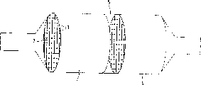
Schematically illustrated in the drawings by a kind of embodiment of the present invention.The honeycomb ceramics 1 that is used as the HC trap by the present invention has passage 2, and they are spaced-apart by dividing plate 3.This honeycomb ceramics 1 especially can be contained in the vent systems 5 of automobile, and it is located at the upstream of one No. three catalyst 4 in this case.At cold-start phase, slowly the exhaust of heating is at first flowed by honeycomb ceramics 1, and wherein in fact all hydrocarbons contained in exhaust are used for the coating of adsorbing hydrocarbon on the dividing plate 3, and especially the zeolite coating is adsorbed.No. three catalysts 4 are then flow through in exhaust.Based on by the favourable geometrical surface of the present invention and the ratio of honeycomb ceramics 1 per unit surface area thermal capacity, thus honeycomb ceramics 1 during this period adsorbing hydrocarbon but No. three catalysts also fail with the time lag of its conversion very short.Almost conversions fully in the exhaust and adsorbed whole hydrocarbons are implemented to be included in impact type ground after this, thereby stack up makes the discharge amount of hydrocarbon less than traditional system.If honeycomb ceramics 1 is additional the effectively catalytically active coatings of accelerated oxidation at least of a catalysis is arranged, then can further help said process.
Be particularly useful for to satisfy by honeycomb ceramics of the present invention in the emission control system of automobile of the strictest environmental protection requirement.
Claims (8)
1. honeycomb ceramics (1), comprise that some can flow through the passage of gas (2), the internal cross section shape of passage and quantity have been determined the unit geometrical surface (GSA) of honeycomb ceramics, and they separate to small part mutually by dividing plate (3), the material of dividing plate and thickness have determined to relate to the unit thermal capacity of per surface area, wherein, honeycomb ceramics has a kind of sorbing material, it is characterized by: honeycomb ceramics (1) is with every liter square metre of [m
2/ l] the unit geometrical surface (GSA) of meter is divided by with your [kJ/ (Km of every square metre of kilojoule of every Kelvin
2)] the unit thermal capacity (CP) that relates to surface area of meter, in room temperature with do not have sorbing material and do not have under the situation that other may coatings, more than or equal to 37.5 every joule of rice Kelvins [mK/J].
2. according to the described honeycomb ceramics of claim 1, it is characterized by: the unit geometrical surface (GSA) of honeycomb ceramics (1) divided by the unit thermal capacity (CP) that relates to surface area more than or equal to 60.
3. according to the described honeycomb ceramics of claim 1, it is characterized by: honeycomb ceramics (1) additionally has a catalytically active coatings, and it plays oxidation at least.
4. according to the described honeycomb ceramics of claim 1, it is characterized by: passage per square inch (cpsi) number is at least 360.
5. according to the described honeycomb ceramics of claim 4, it is characterized by: passage per square inch (cpsi) number is at least 540.
6. according to the described honeycomb ceramics of claim 1, it is characterized by: honeycomb ceramics (1) is piled up or is reeled by sheet metal layers and forms, and the thickness of dividing plate (3) is less than or equal to 40 μ m.
7. according to the described honeycomb ceramics of claim 6, it is characterized by: the thickness of dividing plate (3) is less than or equal to 30 μ m.
8. according to the described honeycomb ceramics of claim 1, it is characterized by: it is the part of Subaru Exhaust Emission Control (5), emission control system (5) also has at least one No. three catalyst (4), and honeycomb ceramics (1) is located at No. three catalysts (4) upstream as hydrocarbon trap.
Applications Claiming Priority (2)
| Application Number | Priority Date | Filing Date | Title |
|---|---|---|---|
| DE19814132.7 | 1998-03-30 | ||
| DE19814132A DE19814132A1 (en) | 1998-03-30 | 1998-03-30 | Honeycomb body with adsorber material, especially for a hydrocarbon trap |
Publications (2)
| Publication Number | Publication Date |
|---|---|
| CN1298471A CN1298471A (en) | 2001-06-06 |
| CN1105822C true CN1105822C (en) | 2003-04-16 |
Family
ID=7862935
Family Applications (1)
| Application Number | Title | Priority Date | Filing Date |
|---|---|---|---|
| CN99805558A Expired - Lifetime CN1105822C (en) | 1998-03-30 | 1999-03-22 | Honeycomb body having an adsorption material especially for a hydrocarbon trap |
Country Status (11)
| Country | Link |
|---|---|
| US (1) | US6656435B1 (en) |
| EP (1) | EP1068431B1 (en) |
| JP (1) | JP2002509805A (en) |
| KR (1) | KR100525038B1 (en) |
| CN (1) | CN1105822C (en) |
| AU (1) | AU3520099A (en) |
| DE (2) | DE19814132A1 (en) |
| ES (1) | ES2179644T3 (en) |
| PL (1) | PL203221B1 (en) |
| RU (1) | RU2213230C2 (en) |
| WO (1) | WO1999050540A1 (en) |
Families Citing this family (8)
| Publication number | Priority date | Publication date | Assignee | Title |
|---|---|---|---|---|
| DE10027401A1 (en) * | 2000-06-02 | 2001-12-20 | Emitec Emissionstechnologie | Device, for adsorbing one component of exhaust gas from vehicle engine, has adsorber with volume calculated by equation, through which exhaust gas is made to flow |
| AU2002346663A1 (en) * | 2001-12-03 | 2003-06-17 | Catalytica Energy Systems, Inc. | System and methods for improved emission control of internal combustion engines |
| JP2005193171A (en) * | 2004-01-08 | 2005-07-21 | Ict:Kk | Exhaust emission control device of internal combustion engine |
| DE102009060290A1 (en) * | 2009-12-23 | 2011-06-30 | Volkswagen AG, 38440 | Exhaust gas cleaning in gasoline engines with direct injection using adsorbers with Partikelabscheidefunktion |
| FR2974735B1 (en) * | 2011-05-03 | 2015-11-20 | Air Liquide | ADSORBER COMPRISING PARALLEL PASSAGE CONTACTORS WITH INTEGRATED INSULATION |
| JP5770040B2 (en) * | 2011-07-28 | 2015-08-26 | 愛三工業株式会社 | Evaporative fuel processing equipment |
| US9581115B2 (en) | 2012-03-02 | 2017-02-28 | Ford Global Technologies, Llc | Induction system including a passive-adsorption hydrocarbon trap |
| DE102016224711B4 (en) * | 2016-12-12 | 2019-08-01 | Continental Automotive Gmbh | Method for operating an electrically heatable catalyst |
Citations (2)
| Publication number | Priority date | Publication date | Assignee | Title |
|---|---|---|---|---|
| EP0582971A1 (en) * | 1992-08-10 | 1994-02-16 | Degussa Aktiengesellschaft | Process for the catalytic purification of automobile exhaust gases with improved cold start behaviour |
| EP0622530A1 (en) * | 1993-03-26 | 1994-11-02 | Ngk Insulators, Ltd. | Exhaust gas purifying apparatus |
Family Cites Families (10)
| Publication number | Priority date | Publication date | Assignee | Title |
|---|---|---|---|---|
| JPS5650716U (en) * | 1979-09-28 | 1981-05-06 | ||
| JPH03141816A (en) | 1989-10-27 | 1991-06-17 | Toyota Motor Corp | Exhaust gas purifier |
| JPH05187228A (en) * | 1991-10-28 | 1993-07-27 | Toyota Motor Corp | Exhaust emission purifier |
| US5316991A (en) | 1991-11-08 | 1994-05-31 | Ford Motor Company | Exhaust treating system for lean-burn CNG engine |
| JP3282344B2 (en) | 1994-01-28 | 2002-05-13 | 日産自動車株式会社 | Exhaust gas purification device |
| DE19502345B4 (en) | 1994-02-11 | 2006-03-02 | Volkswagen Ag | An exhaust gas purification device for an internal combustion engine with an adsorber and a downstream catalytic converter |
| JPH07232082A (en) | 1994-02-22 | 1995-09-05 | Nippondenso Co Ltd | Catalyst converter for purification of exhaust gas |
| JP3210535B2 (en) | 1994-12-20 | 2001-09-17 | 新日本製鐵株式会社 | Metal carrier for purifying exhaust gas with low heat capacity and low back pressure |
| JPH08257365A (en) | 1995-03-23 | 1996-10-08 | Kawasaki Heavy Ind Ltd | Method and apparatus for denitrating exhaust gas |
| JPH09192503A (en) | 1996-01-25 | 1997-07-29 | Nippon Steel Corp | Low heat capacity metal carrier |
-
1998
- 1998-03-30 DE DE19814132A patent/DE19814132A1/en not_active Withdrawn
-
1999
- 1999-03-22 RU RU2000127723/06A patent/RU2213230C2/en not_active IP Right Cessation
- 1999-03-22 JP JP2000541413A patent/JP2002509805A/en active Pending
- 1999-03-22 AU AU35200/99A patent/AU3520099A/en not_active Abandoned
- 1999-03-22 EP EP99916862A patent/EP1068431B1/en not_active Expired - Lifetime
- 1999-03-22 DE DE59901805T patent/DE59901805D1/en not_active Expired - Lifetime
- 1999-03-22 WO PCT/EP1999/001923 patent/WO1999050540A1/en active IP Right Grant
- 1999-03-22 KR KR10-2000-7010860A patent/KR100525038B1/en not_active IP Right Cessation
- 1999-03-22 ES ES99916862T patent/ES2179644T3/en not_active Expired - Lifetime
- 1999-03-22 PL PL343002A patent/PL203221B1/en unknown
- 1999-03-22 CN CN99805558A patent/CN1105822C/en not_active Expired - Lifetime
-
2000
- 2000-09-29 US US09/677,325 patent/US6656435B1/en not_active Expired - Lifetime
Patent Citations (2)
| Publication number | Priority date | Publication date | Assignee | Title |
|---|---|---|---|---|
| EP0582971A1 (en) * | 1992-08-10 | 1994-02-16 | Degussa Aktiengesellschaft | Process for the catalytic purification of automobile exhaust gases with improved cold start behaviour |
| EP0622530A1 (en) * | 1993-03-26 | 1994-11-02 | Ngk Insulators, Ltd. | Exhaust gas purifying apparatus |
Also Published As
| Publication number | Publication date |
|---|---|
| EP1068431B1 (en) | 2002-06-19 |
| US6656435B1 (en) | 2003-12-02 |
| JP2002509805A (en) | 2002-04-02 |
| ES2179644T3 (en) | 2003-01-16 |
| PL343002A1 (en) | 2001-07-30 |
| PL203221B1 (en) | 2009-09-30 |
| KR100525038B1 (en) | 2005-11-02 |
| RU2213230C2 (en) | 2003-09-27 |
| DE59901805D1 (en) | 2002-07-25 |
| EP1068431A1 (en) | 2001-01-17 |
| KR20010042312A (en) | 2001-05-25 |
| CN1298471A (en) | 2001-06-06 |
| DE19814132A1 (en) | 1999-10-14 |
| AU3520099A (en) | 1999-10-18 |
| WO1999050540A1 (en) | 1999-10-07 |
Similar Documents
| Publication | Publication Date | Title |
|---|---|---|
| US6029441A (en) | Method for exhaust gas purification and system for exhaust gas purification used therein | |
| AU661600B2 (en) | Apparatus and method for modifying gaseous mixtures | |
| JP3311051B2 (en) | Exhaust gas purification method and apparatus | |
| JP3526084B2 (en) | Adsorption / catalyst for exhaust gas purification, adsorbent, exhaust gas purification system and exhaust gas purification method | |
| CN102177328A (en) | Regulating strategy for a catalytic converter concept for exhaust-gas aftertreatment having a plurality of nitrogen oxide storage catalytic converters | |
| JP2016101581A (en) | Multi-area catalyst construct | |
| US7094728B2 (en) | Method for control of washcoat distribution along channels of a particulate filter substrate | |
| US10107162B2 (en) | Catalyst subassembly, device comprising same for purifying exhaust gases from an internal combustion engine, modular system for the subassembly, and method for manufacturing the subassembly | |
| CN1105822C (en) | Honeycomb body having an adsorption material especially for a hydrocarbon trap | |
| EP0945167A2 (en) | Catalyst and system for exhault gas purification | |
| WO2005064131A1 (en) | Apparatus for purifying exhaust gas | |
| US8062990B2 (en) | Metal catalyst carriers and catalyst members made therefrom | |
| CN104145094B (en) | Exhaust gas after-treatment components with HC absorber functions and the exhaust gas apparatus with this part | |
| CA2128562A1 (en) | Modified large pore zeolites for trapping alkenes | |
| EP1627137B1 (en) | Exhaust-gas purification system with particulate filter and method of operation thereof with improved regeneration of the particulate filter | |
| CA2240704C (en) | System for exhaust gas purification | |
| EP0895803B1 (en) | Use of a system for purifying exhaust gas | |
| CN1568218A (en) | Small-volume nox adsorber | |
| JP2018062882A (en) | Exhaust emission control system | |
| EP1286768B1 (en) | Pliable metal catalyst carriers, conformable catalyst members made therefrom and methods of installing the same | |
| CN2368741Y (en) | Thermal resistant three-component catalyst device | |
| CN1429312A (en) | Low-volume adsorber | |
| US20050092688A1 (en) | System and process for treating contaminated fluid system |
Legal Events
| Date | Code | Title | Description |
|---|---|---|---|
| C06 | Publication | ||
| PB01 | Publication | ||
| C10 | Entry into substantive examination | ||
| SE01 | Entry into force of request for substantive examination | ||
| C14 | Grant of patent or utility model | ||
| GR01 | Patent grant | ||
| CX01 | Expiry of patent term |
Granted publication date: 20030416 |
|
| CX01 | Expiry of patent term |