CN110479861B - Machining process and machining equipment for automobile seat framework side plate - Google Patents
Machining process and machining equipment for automobile seat framework side plate Download PDFInfo
- Publication number
- CN110479861B CN110479861B CN201910645103.6A CN201910645103A CN110479861B CN 110479861 B CN110479861 B CN 110479861B CN 201910645103 A CN201910645103 A CN 201910645103A CN 110479861 B CN110479861 B CN 110479861B
- Authority
- CN
- China
- Prior art keywords
- steel plate
- punching
- trimming
- automobile seat
- side plate
- Prior art date
- Legal status (The legal status is an assumption and is not a legal conclusion. Google has not performed a legal analysis and makes no representation as to the accuracy of the status listed.)
- Active
Links
Images


Classifications
-
- B—PERFORMING OPERATIONS; TRANSPORTING
- B21—MECHANICAL METAL-WORKING WITHOUT ESSENTIALLY REMOVING MATERIAL; PUNCHING METAL
- B21C—MANUFACTURE OF METAL SHEETS, WIRE, RODS, TUBES OR PROFILES, OTHERWISE THAN BY ROLLING; AUXILIARY OPERATIONS USED IN CONNECTION WITH METAL-WORKING WITHOUT ESSENTIALLY REMOVING MATERIAL
- B21C51/00—Measuring, gauging, indicating, counting, or marking devices specially adapted for use in the production or manipulation of material in accordance with subclasses B21B - B21F
-
- B—PERFORMING OPERATIONS; TRANSPORTING
- B21—MECHANICAL METAL-WORKING WITHOUT ESSENTIALLY REMOVING MATERIAL; PUNCHING METAL
- B21D—WORKING OR PROCESSING OF SHEET METAL OR METAL TUBES, RODS OR PROFILES WITHOUT ESSENTIALLY REMOVING MATERIAL; PUNCHING METAL
- B21D35/00—Combined processes according to or processes combined with methods covered by groups B21D1/00 - B21D31/00
- B21D35/002—Processes combined with methods covered by groups B21D1/00 - B21D31/00
-
- B—PERFORMING OPERATIONS; TRANSPORTING
- B21—MECHANICAL METAL-WORKING WITHOUT ESSENTIALLY REMOVING MATERIAL; PUNCHING METAL
- B21D—WORKING OR PROCESSING OF SHEET METAL OR METAL TUBES, RODS OR PROFILES WITHOUT ESSENTIALLY REMOVING MATERIAL; PUNCHING METAL
- B21D53/00—Making other particular articles
- B21D53/88—Making other particular articles other parts for vehicles, e.g. cowlings, mudguards
-
- B—PERFORMING OPERATIONS; TRANSPORTING
- B23—MACHINE TOOLS; METAL-WORKING NOT OTHERWISE PROVIDED FOR
- B23P—METAL-WORKING NOT OTHERWISE PROVIDED FOR; COMBINED OPERATIONS; UNIVERSAL MACHINE TOOLS
- B23P15/00—Making specific metal objects by operations not covered by a single other subclass or a group in this subclass
Abstract
The invention discloses a processing technology and equipment for a side plate of an automobile seat framework, which specifically comprise the following steps: the steel plate strip is conveyed to a leveling machine through a feeding machine, and then the steel plate strip 16 is leveled and conveyed to the next working procedure; step 3, punching for the first time; step 4, cutting an arc-shaped edge cutting opening; step 5, trimming for the first time; step 6, stretching; step 7, shaping; 8, trimming for the second time; step 9, trimming for the third time and punching for the second time; step 10, fourth trimming and chamfering; step 11, performing an idle step; step 12, flanging; step 13, inclining the edge; step 14, an idle step; step 15, punching, hole flanging and side punching for the third time; step 16, straightening; step 17, semi-shearing; and 18, blanking and cutting waste materials, wherein the steps 3 to 18 are completed by performing pipeline operation in one device. The invention improves the working efficiency.
Description
Technical Field
The invention relates to the technical field of automobile seat framework side plate machining, in particular to a machining process and machining equipment for an automobile seat framework side plate.
Background
The seat for a vehicle is composed of an inner frame and an outer cover, and the comfort, firmness and service life of the seat are mainly determined by the structure of the inner frame, including the structures and connection relations of various components constituting the inner frame. Among them, the side plates of the car seat back are two side plates of the seat back, which are key parts for fixing the upper top plate and the lower bottom plate and supporting the back tie bar, so that a large amount of production is required.
At present, need process a plurality of processes when processing the curb plate of car seat back, and each process processing needs the manual work to carry after accomplishing then place the mould that next process corresponds in and process, increased the cost of labor of processing on the contrary like this, and machining efficiency is lower relatively, must cut off between the simultaneous processing in-process and the last process, lead to the extravagant serious outside of material, the processing cost of final whole product is also corresponding too high, consequently needs to improve.
Disclosure of Invention
The invention aims to solve the defects of the prior art and provide a processing technology and processing equipment for a side plate of an automobile seat framework, which improve the working efficiency and the material utilization rate.
In order to achieve the purpose, the processing technology of the automobile seat framework side plate comprises the following steps:
step 1, dividing a steel plate coil stock into steel plate strips with designed size and width, and mounting the divided steel plate strips on a pushing and feeding mechanism;
step 5, cutting edges for the first time, namely taking the highest points of the two arc-shaped edge cutting openings, and cutting the highest points of the two arc-shaped edge cutting openings as two end points through a cutting tool; forming a cutting line;
8, trimming for the second time; trimming the edge to be cut of the right side of the shaped automobile seat framework side plate substrate;
Further, when the shaping is performed in the step 7, a database of the size, shape and depth requirements of the automobile seat framework side plate substrate is preset, the database is compared with the preset database in real time, and the shaping is stopped after the requirements are met.
The invention also discloses processing equipment of the automobile seat framework side plate, which comprises a pushing and feeding mechanism capable of driving the whole steel plate strip to be transported, and the processing equipment also comprises the following components:
the continuous positioning die is positioned below the continuous positioning die and used for placing steel plate strips and realizing the integrated punching operation of all the steps of punching for the first time, cutting an arc-shaped trimming opening, trimming for the first time, stretching, shaping, trimming for the second time, trimming for the third time, punching for the second time, trimming and chamfering for the fourth time, idle step, flanging, pressing and inclining edges, idle step, punching for the third time, hole flanging, side punching, straightening, half shearing and blanking of the steel plate strips;
a continuous moving die positioned above and matched with the continuous positioning die;
the driving cylinder drives the continuous moving die to move towards the continuous positioning die;
the data monitoring sensor is used for detecting that the steel plate strips pushed by the feeding mechanism to the continuous positioning die are pushed from one step to the next step, and then the feeding mechanism is pushed to stop pushing;
the controller is electrically connected with the data monitoring sensor, the driving cylinder and the pushing and feeding mechanism, controls the cylinder to drive the continuous moving die to press down once and match with the continuous positioning die to realize the operation process corresponding to each step after primary data of the data monitoring sensor is obtained, then drives the continuous moving die to reset, and controls the pushing and feeding mechanism to continue to push steel plate strips;
the front side and the rear side of the continuous moving die are provided with guide rods at intervals, and the front side and the rear side of the continuous positioning die are provided with guide holes matched with the guide rods.
Further, in order to improve the accuracy of punching press, improve the punching press effect, data monitoring sensor is stay cord displacement sensor, stay cord displacement sensor detects steel sheet strip material from one step to next step after, promotes feeding mechanism and stops the concrete step of propelling movement as follows:
s1, mounting a stay cord displacement sensor on the continuous positioning die at the front end of the first punching position in advance, and fixing a tension monitoring end of the stay cord displacement sensor at the front end of a guide through hole at the front side corresponding to the first punching position of the steel plate strip and moving along with the steel plate strip;
s2, presetting an initial walking distance as D0And is held, said D0The value of (A) is the linear distance needed to walk according to the work of the steel plate strip from one step to the next step in advance;
s3, editing the steel plate strip in sequence according to the distance from the first step to the last step of each process, and using DnRepresents; n represents a process step and is greater than 3;
s4, the controller obtains the pull rope displacement sensor when the steel plate strip material moves in real timeData value D ofnAnd using a stamping conversion formula: Δ D = Dn-Dn-1Obtaining a value of DeltaD when DeltaD equals D0The distance is used as the accurate distance for moving the steel plate strip from one step to the next step, and at the moment, the pushing and feeding mechanism is controlled to stop pushing and the driving cylinder is driven to work and press down to perform the process of matching the continuous positioning die with the continuous moving die; after one-time stamping, stamping D before the stampingnThe data continues to run as the decremented in the press conversion equation before the next press.
Further, in order to improve the detection correctness and avoid excessive product scrapping in the later period, a camera for photographing and detecting the shaping step is arranged on the continuous moving die and is electrically connected with the controller.
Furthermore, in order to facilitate disassembly, first base plates are arranged above the continuous moving die at intervals, first positioning plates are connected to the upper portions of all the first base plates, second base plates are arranged below the continuous moving die at intervals, and second positioning plates are connected to the upper portions of all the second base plates.
Furthermore, in order to improve the accurate positioning of the sequential stamping, detection pressure rods are arranged at intervals at the front side and the rear side of the continuous positioning die, electric shock switches matched with the detection pressure rods are arranged at the front side and the rear side of the continuous moving die and are electrically connected with the controller, and the process that the driving cylinder is controlled to stop for 3-4s and then the continuous moving die is driven to reset after the controller detects signals of all the electric shock switches is realized.
The technical effects of the processing technology and the processing equipment of the automobile seat framework side plate obtained by the invention are as follows: the method adopting the process steps completes the whole steps on one device in the processing process, so that the whole working efficiency is higher, the manual operation is not needed, the labor cost is reduced, the waste materials can be cut off for many times in the whole processing process until the whole steps are completed, and the problem of material waste can be avoided.
Drawings
FIG. 1 is a schematic view of a side panel of a seat frame for an automobile from step 3 to step 18 in example 1;
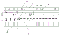
FIG. 2 is a schematic structural view of an apparatus for processing a side plate of a seat frame in an automobile according to embodiment 1;
FIG. 3 is an exploded view of the structure of the progressive cavity die and the progressive die in the absence of the guide bar in example 1;
fig. 4 is a schematic view showing the initial position of the data monitoring sensor in example 1.
In the figure: the device comprises a pushing and feeding mechanism 1, a continuous positioning die 2, a continuous moving die 3, a driving cylinder 4, a data monitoring sensor 5, a controller 6, a guide rod 7, a guide hole 8, a camera 9, a first base plate 10, a first positioning plate 11, a second base plate 12, a second positioning plate 13, a detection pressure rod 14, an electric shock switch 15, a steel plate strip 16, a stretcher 17 and an edge cutter 18.
Detailed Description
The invention is further illustrated with reference to the following figures and examples.
Example 1:
as shown in fig. 1, the processing technology of the side plate of the automobile seat framework provided by the embodiment specifically includes the following steps:
step 1, dividing a steel plate coil stock into steel plate strips with designed size and width, and mounting the divided steel plate strips on a pushing and feeding mechanism 1;
step 5, cutting edges for the first time, namely taking the highest points of the two arc-shaped edge cutting openings, and cutting the highest points of the two arc-shaped edge cutting openings as two end points through a cutting tool; forming a cutting line;
8, trimming for the second time; trimming the edge to be cut of the right side of the shaped automobile seat framework side plate substrate;
The method adopting the process steps completes the whole steps on one device in the processing process, so that the whole working efficiency is higher, the manual operation is not needed, the labor cost is reduced, the waste materials can be cut off for many times in the whole processing process until the whole steps are completed, and the problem of material waste can be avoided.
Further, when the shaping is performed in the step 7, a database of the size, shape and depth requirements of the automobile seat framework side plate substrate is preset, the database is compared with the preset database in real time, and the shaping is stopped after the requirements are met.
As shown in fig. 2 and fig. 3, the embodiment further discloses a processing device for a side plate of an automobile seat framework, which includes a pushing and feeding mechanism 1 capable of conveying a whole steel plate strip 16, and further includes the following components:
the continuous positioning die 2 is positioned below and used for placing steel plate strips and can realize the integrated punching operation of all the steps of punching for the first time, cutting an arc-shaped trimming opening, trimming for the first time, stretching, shaping, trimming for the second time, trimming for the third time, punching for the second time, trimming for the fourth time, chamfering, idle working, flanging, pressing for inclining, idle working, punching for the third time, hole flanging, side punching, straightening, half shearing and blanking of the steel plate strips;
a continuous moving die 3 located above and engaged with the continuous positioning die 2;
a driving cylinder 4 for driving the continuous moving die 3 to move towards the continuous positioning die 2;
a data monitoring sensor 5 for detecting that the feeding mechanism 1 is pushed to push the steel plate strips on the continuous positioning die 2 from one step to the next step, and then the feeding mechanism 1 is pushed to stop pushing;
the controller 6 is electrically connected with the data monitoring sensor 5, the driving cylinder 4 and the pushing and feeding mechanism 1, controls the driving cylinder 4 to drive the continuous moving die 3 to press down once to be matched with the continuous positioning die 2 to realize the operation process corresponding to each step after primary data of the data monitoring sensor 5 is obtained, then drives the continuous moving die 3 to reset, and controls the pushing and feeding mechanism 1 to continue to push steel plate strips;
wherein, the front and the back of the continuous moving die 3 are provided with guide rods 7 at intervals, and the front and the back of the continuous positioning die 2 are provided with guide holes 8 matched with the guide rods 7.
As shown in fig. 4, further, in order to improve the accuracy of the stamping and improve the stamping effect, the data monitoring sensor 5 is a pull rope displacement sensor, and after the pull rope displacement sensor detects that a steel plate strip is pushed from one step to the next step, the specific steps of pushing the feeding mechanism 1 to stop pushing are as follows:
s1, mounting a stay cord displacement sensor on the continuous positioning die 2 right at the front end of the first punching position in advance, fixing a tension monitoring end of the stay cord displacement sensor on the front end of a guide through hole on the front side corresponding to the first punching position of the steel plate strip and moving along with the steel plate strip;
s2, presetting and maintaining an initial walking distance D0, wherein the value of D0 is the linear distance needed to walk from one step to the next step according to the steel plate strip;
s3, editing the steel plate strips in sequence according to the distance of each process from the first step to the last step, and expressing the distance by Dn; n represents a process step and is greater than 3;
s4, the controller 6 obtains the data value Dn of the pull rope displacement sensor when the steel plate strip moves in real time, and utilizes a stamping conversion formula: delta D = Dn-Dn-1 and a value of Delta D is obtained when Delta D equals D0The distance is used as the accurate distance for moving the steel plate strip from one step to the next step, the pushing and feeding mechanism 1 is controlled to stop pushing at the moment, and the driving cylinder 4 is driven to work and press down to carry out the process of matching the continuous positioning die 2 and the continuous moving die 3; after one-time stamping, the Dn data before the stamping is taken as a decrement in a conversion formula of stamping before the next stamping to continue operation.
In this embodiment the value of n should be 18, i.e., Dn-D for the fourth step of stamping to the seventeenth step of stamping4、D5、D6、D7、D8、D9、D10、D11、D12、D13、D14、D15、D16、D17、D18; D4Position ofThe displacement is the displacement when the pull rope displacement sensor on the positioning die 2 at the front end of the first punching position in the step 3 is taken as an initial position, and the tension monitoring end of the pull rope displacement sensor moves from the initial position along with the steel plate strip to reach the station in the step 4, and the stamping conversion formula at the moment is as follows: Δ D = Dn-Dn-1,Dn-1I.e. D3That is, the pull rope displacement sensor is not displaced in step 3, so that the displacement of D3 is 0 at this time, that is, D is obtained by the pull rope displacement sensor in real time4As long as Δ D = D is ensured4-D3=D0When the steel plate strip finishes the displacement process from the step 3 to the step 4, immediately controlling the pushing and feeding mechanism 1 to stop pushing, and controlling the driving cylinder 4 to work and press down to perform the process of matching the continuous positioning die 2 and the continuous moving die 3; and storing the data of D4, and then continuing to drive the pushing and feeding mechanism 1 to work, and acquiring the displacement of D5 according to the steps, wherein the stamping conversion formula is as follows: Δ D = Dn-Dn-1Is decremented by Dn-1By D4Instead, then obtain D in real time5As long as Δ D = D is ensured5-D4=D0When the steel plate strip finishes the displacement process from the 4 th step to the 5 th step, immediately controlling the pushing and feeding mechanism 1 to stop pushing, and driving the driving cylinder 4 to work and press down to perform the process of matching the continuous positioning die 2 and the continuous moving die 3; and D5The data are stored, the working process of driving the air cylinder and pushing the feeding mechanism 1 is finally carried out through the method, the stamping precision operation process is finally improved, and therefore the initial walking distance D is preset for ensuring the stamping precision0Value, D needs to be guaranteed0The value of (b) is just a distance value from the center point of one guide through hole to the center point of the leading-end adjacent guide through hole, and the position of the corresponding equipment on each punching process on the continuously movable die 3 needs to be set in advance according to a specific position.
Further, in order to improve the detection accuracy and avoid excessive product scrap at the later stage, a camera 9 for photographing and detecting the shaping step is arranged on the continuous moving die 3, the camera 9 is electrically connected with the controller 6, a database of the size, shape and depth requirements of the automobile seat framework side plate substrate is arranged in the controller 6 in advance, the image information for real-time shaping is obtained through the camera 9, then the image information is compared with the preset database, and shaping is stopped after the requirements are met.
Further, in order to facilitate disassembly, the first base plates 10 are arranged on the continuously movable die 3 at intervals, the first positioning plates 11 are connected to the upper portions of the first base plates 10, the second base plates 12 are arranged on the lower portions of the continuously movable die 2 at intervals, the second positioning plates 13 are connected to the upper portions of the second base plates 12, and the dies are convenient to replace in the later period through the structural design.
Further, in order to improve accurate positioning of sequential stamping, detection pressure rods 14 are arranged at the front side and the rear side of the continuous positioning die 2 at intervals, electric shock switches 15 matched with the detection pressure rods 14 are arranged at the front side and the rear side of the continuous moving die 3, the electric shock switches 15 are electrically connected with the controller 6, the driving air cylinder 4 is controlled to stop for 3-4s after the controller 6 detects signals of all the electric shock switches 15, and then the continuous moving die 3 is driven to reset.
A stretcher 17 and a trimming device 18 are provided at positions corresponding to the progressive die 2.
When the continuous positioning device works, a steel plate strip 16 is sent into the continuous positioning die 2 by driving the pushing and feeding mechanism 1 to work, then the pushing is stopped after the steel plate strip is in place, the data monitoring sensor 5 detects that the pushing and feeding mechanism 1 stops once conveying, the data is transmitted to the controller 6, the driving cylinder 4 is driven to work, at the moment, the driving cylinder 4 drives the continuous movable die 3 to press down once to be matched with the continuous positioning die 2 to realize the operation process corresponding to each step, then the continuous movable die 3 is driven to reset, the pushing and feeding mechanism 1 is controlled to push the steel plate strip 16 continuously from one step to the next step and then to stop, the data monitoring sensor 5 detects that the pushing and feeding mechanism 1 stops once conveying, the data is transmitted to the controller 6 to drive the driving cylinder 4 to work, at the moment, the driving cylinder 4 drives the continuous movable die 3 to press down once to be matched with the continuous positioning die 2 to realize, this realizes a reciprocating operation.
How each step works specifically and the selection of the device in this embodiment are conventional means in the art, and the selection model and programming of the controller are conventional techniques, and therefore will not be described in detail.
Claims (7)
1. The machining process of the automobile seat framework side plate is characterized by comprising the following steps:
step 1, dividing a steel plate coil stock into steel plate strips with designed size and width, and mounting the divided steel plate strips on a pushing and feeding mechanism (1);
step 2, the steel plate strip is conveyed to a leveling machine through a pushing and feeding mechanism (1), and then the steel plate strip is leveled and conveyed to the next procedure;
step 3, punching for the first time, namely punching a guide through hole on each of the front side and the rear side of the steel plate strip, which is perpendicular to the feeding direction, on the horizontal plane;
step 4, cutting the arc-shaped trimming opening, and trimming the inner edges close to the two guide through holes to form the arc-shaped trimming opening; first extension cut openings are arranged on two sides of the arc-shaped trimming opening on the rear side, and second extension cut openings are arranged on two sides of the arc-shaped trimming opening on the front side;
step 5, cutting edges for the first time, namely taking the highest points of the two arc-shaped edge cutting openings, and cutting the highest points of the two arc-shaped edge cutting openings as two end points through a cutting tool; forming a cutting line;
step 6, stretching, namely stretching the automobile seat framework side plate substrate formed by two adjacent cutting lines;
step 7, shaping, namely shaping the stretched automobile seat framework side plate substrate to form a basic automobile seat framework side plate appearance structure;
8, trimming for the second time; trimming the edge to be cut of the right side of the shaped automobile seat framework side plate substrate;
step 9, performing third trimming and second punching, performing trimming processing on the edge to be trimmed on the left side of the shaped automobile seat framework side plate substrate, and performing internal punching processing on the shaped automobile seat framework side plate substrate;
step 10, fourth trimming and chamfering, namely trimming the left and right residual portions to be trimmed of the trimmed automobile seat framework side plate substrate, and chamfering the positions needing chamfering in the automobile seat framework side plate substrate;
step 11, performing idle operation, not performing any operation, and performing idle operation processing;
step 12, flanging, namely flanging the automobile seat framework side plate substrate;
step 13, performing edge-oblique pressing treatment on the automobile seat framework side plate substrate;
step 14, performing idle step, not performing any operation, and performing idle step processing;
step 15, punching, hole flanging and side punching for the third time, and sequentially punching, hole flanging and side punching the automobile seat framework side plate substrate;
step 16, straightening, namely straightening the joint of the automobile seat framework side plate substrate and the steel plate strip;
step 17, performing half shearing, namely performing half shearing treatment on the joint of the automobile seat framework side plate substrate and the steel plate strip;
step 18, blanking and waste cutting treatment; wherein, the steps 3 to 18 are all completed by pipeline operation in one device.
2. The process for machining a side plate of an automobile seat framework as claimed in claim 1, wherein in the step 7, when the shaping is performed, a database of the size, shape and depth requirements of the base plate of the side plate of the automobile seat framework is preset, the database is compared with the preset database in real time, and the shaping is stopped after the requirements are met.
3. The utility model provides a processing equipment of car seat skeleton curb plate, is including promoting feeding mechanism (1) that can drive whole steel sheet strip and expect to transport, its characterized in that still includes following part:
the continuous positioning die (2) is positioned below and used for placing steel plate strips and can realize the integrated punching operation of all the steps of punching for the first time, cutting an arc-shaped trimming opening, trimming for the first time, stretching, shaping, trimming for the second time, trimming for the third time, punching for the second time, trimming and chamfering for the fourth time, idle step, flanging, pressing edge to be oblique, idle step, punching for the third time, hole flanging, side punching, straightening, half shearing and blanking of the steel plate strips;
a continuous moving die (3) which is positioned above and matched with the continuous positioning die (2);
a driving cylinder (4) for driving the continuous moving die (3) to move towards the continuous positioning die (2);
a data monitoring sensor (5) for detecting that the feeding mechanism (1) is pushed to push the steel plate strips on the continuous positioning die (2) from one step to the next step and then pushing the feeding mechanism (1) to stop pushing;
the controller (6) is electrically connected with the data monitoring sensor (5), the driving cylinder (4) and the pushing and feeding mechanism (1), so that after primary data of the data monitoring sensor (5) are acquired, the driving cylinder (4) is controlled to drive the continuous moving die (3) to press down for one time to be matched with the continuous positioning die (2) to realize an operation process corresponding to each step, then the continuous moving die (3) is driven to reset, and the pushing and feeding mechanism (1) is controlled to continue to push steel plate strips;
guide rods (7) are arranged on the front side and the rear side of the continuous moving die (3) at intervals, and guide holes (8) matched with the guide rods (7) are arranged on the front side and the rear side of the continuous positioning die (2).
4. A device for processing a side plate of a seat frame of an automobile as claimed in claim 3, wherein the data monitoring sensor (5) is a pull rope displacement sensor, and the pull rope displacement sensor detects that the steel plate strip is pushed to stop pushing after one step to the next step by the following specific steps:
s1, mounting a stay cord displacement sensor on the continuous positioning die (2) right at the front end of the first punching position in advance, fixing a tension monitoring end of the stay cord displacement sensor on the front end position of a guide through hole on the front side corresponding to the first punching position of the steel plate strip and moving along with the steel plate strip;
s2, presetting an initial walking distance as D0And is held, said D0The value of (A) is the linear distance needed to walk according to the work of the steel plate strip from one step to the next step in advance;
s3, editing the steel plate strip in sequence according to the distance from the first step to the last step of each process, and using DnRepresents; n represents a process step and is greater than 3;
s4, the controller (6) acquires the data value Dn of the pull rope displacement sensor when the steel plate strip moves in real time, and utilizes a stamping conversion formula: Δ D = Dn-Dn-1Obtaining a value of DeltaD when DeltaD equals D0The steel plate strip is used as an accurate distance for moving from one step to the next step, the pushing and feeding mechanism (1) is controlled to stop pushing at the moment, and the driving cylinder (4) is driven to work and press down to perform the process of matching the continuous positioning die (2) with the continuous moving die (3); after one-time stamping, stamping D before the stampingnThe data continues to run as the decremented in the press conversion equation before the next press.
5. A processing device of a side plate of a seat frame of an automobile according to claim 3 or 4, characterized in that a camera (9) for photographing and detecting the shaping step is arranged on the continuous moving die (3), and the camera (9) is electrically connected with the controller (6).
6. A processing device for side plates of a seat frame of an automobile according to claim 3 or 4, characterized in that first cushion plates (10) are arranged above the continuous moving die (3) at intervals, first positioning plates (11) are connected above all the first cushion plates (10), second cushion plates (12) are arranged below the continuous positioning die (2) at intervals, and second positioning plates (13) are connected above all the second cushion plates (12).
7. The processing equipment for the automobile seat framework side plate is characterized in that detection pressure rods (14) are arranged at intervals at the front side and the rear side of the continuous positioning die (2), electric shock switches (15) matched with the detection pressure rods (14) are arranged at the front side and the rear side of the continuous movable die (3), the electric shock switches (15) are electrically connected with the controller (6), and the process that after the controller (6) detects signals of all the electric shock switches (15), the driving cylinder (4) is controlled to stop for 3-4s, and then the continuous movable die (3) is driven to reset is realized.
Priority Applications (1)
| Application Number | Priority Date | Filing Date | Title |
|---|---|---|---|
| CN201910645103.6A CN110479861B (en) | 2019-07-17 | 2019-07-17 | Machining process and machining equipment for automobile seat framework side plate |
Applications Claiming Priority (1)
| Application Number | Priority Date | Filing Date | Title |
|---|---|---|---|
| CN201910645103.6A CN110479861B (en) | 2019-07-17 | 2019-07-17 | Machining process and machining equipment for automobile seat framework side plate |
Publications (2)
| Publication Number | Publication Date |
|---|---|
| CN110479861A CN110479861A (en) | 2019-11-22 |
| CN110479861B true CN110479861B (en) | 2020-10-27 |
Family
ID=68547332
Family Applications (1)
| Application Number | Title | Priority Date | Filing Date |
|---|---|---|---|
| CN201910645103.6A Active CN110479861B (en) | 2019-07-17 | 2019-07-17 | Machining process and machining equipment for automobile seat framework side plate |
Country Status (1)
| Country | Link |
|---|---|
| CN (1) | CN110479861B (en) |
Families Citing this family (1)
| Publication number | Priority date | Publication date | Assignee | Title |
|---|---|---|---|---|
| CN113634680B (en) * | 2021-06-11 | 2023-07-14 | 苏州铭峰精密机械有限公司 | Forming method of automobile antenna support |
Citations (6)
| Publication number | Priority date | Publication date | Assignee | Title |
|---|---|---|---|---|
| KR20100073286A (en) * | 2008-12-23 | 2010-07-01 | 조일공업주식회사 | Method of manufacturing hinge bracket assembly for rear seat used in vehicle by using progressive mold and bracket manufactured by the same |
| CN202555684U (en) * | 2011-12-14 | 2012-11-28 | 天津市英辰精密模具有限公司 | Connection safety board die |
| CN103658388A (en) * | 2013-09-30 | 2014-03-26 | 浙江龙生汽车部件股份有限公司 | Progressive die and method for producing automobile seat sliding way retainer |
| CN104772394A (en) * | 2015-04-16 | 2015-07-15 | 浙江雅虎汽车部件有限公司 | Automobile handrail reinforced left-and-right support continuous die |
| CN107377760A (en) * | 2017-08-29 | 2017-11-24 | 无锡诺飞高新技术有限公司 | Car door after-poppet continuous stamping die and its process for stamping |
| CN206716836U (en) * | 2017-04-14 | 2017-12-08 | 台光五金制品(东莞)有限公司 | A kind of continuously elongated mould of automobile motor lid |
-
2019
- 2019-07-17 CN CN201910645103.6A patent/CN110479861B/en active Active
Patent Citations (6)
| Publication number | Priority date | Publication date | Assignee | Title |
|---|---|---|---|---|
| KR20100073286A (en) * | 2008-12-23 | 2010-07-01 | 조일공업주식회사 | Method of manufacturing hinge bracket assembly for rear seat used in vehicle by using progressive mold and bracket manufactured by the same |
| CN202555684U (en) * | 2011-12-14 | 2012-11-28 | 天津市英辰精密模具有限公司 | Connection safety board die |
| CN103658388A (en) * | 2013-09-30 | 2014-03-26 | 浙江龙生汽车部件股份有限公司 | Progressive die and method for producing automobile seat sliding way retainer |
| CN104772394A (en) * | 2015-04-16 | 2015-07-15 | 浙江雅虎汽车部件有限公司 | Automobile handrail reinforced left-and-right support continuous die |
| CN206716836U (en) * | 2017-04-14 | 2017-12-08 | 台光五金制品(东莞)有限公司 | A kind of continuously elongated mould of automobile motor lid |
| CN107377760A (en) * | 2017-08-29 | 2017-11-24 | 无锡诺飞高新技术有限公司 | Car door after-poppet continuous stamping die and its process for stamping |
Also Published As
| Publication number | Publication date |
|---|---|
| CN110479861A (en) | 2019-11-22 |
Similar Documents
| Publication | Publication Date | Title |
|---|---|---|
| CN104259295B (en) | Car door column plate workpiece stamping line and its mechanical arm | |
| JP3685961B2 (en) | Molding press | |
| CN104525665A (en) | Automatic stamping method and production line thereof | |
| CN102218484B (en) | Manufacturing method and manufacturing equipment for nested composite section member | |
| CN108326421B (en) | Laser welding machine with multi-station workbench and visual recognition device | |
| CN204523915U (en) | A kind of numerical control folding brake | |
| CN107186114A (en) | A kind of electric cooker collet automatic production line | |
| CN110479861B (en) | Machining process and machining equipment for automobile seat framework side plate | |
| CN105252748B (en) | A kind of mould inscribe shaped device of forming machine | |
| CN208321790U (en) | Battery aluminum shell process equipment | |
| CN105377470A (en) | Forming press | |
| CN115674724B (en) | Efficient prepreg layering method and preforming device | |
| CN114798873B (en) | High-speed punch forming process for pipe joint and integrated equipment thereof | |
| CN106694750B (en) | A kind of stirrup cavity plate for reinforcing steel bar hoop bending shaping equipment | |
| CN206868901U (en) | A kind of vehicle dormer window class trimming apparatus for shaping | |
| CN110102639B (en) | Punch forming composite die for automobile seat framework and machining process of punch forming composite die | |
| CN209300346U (en) | A kind of sole press machine | |
| CN208787348U (en) | A kind of stamping die | |
| CN106975692B (en) | A kind of automobile body-in-white blanking apparatus | |
| CN207983533U (en) | A kind of liquid film molding conveying punch die structure | |
| CN206747979U (en) | A kind of automatic bending cutting machine of electronic box | |
| CN206951960U (en) | The automobile back door upper hinge reinforcing plate progressive die | |
| CN209272262U (en) | A kind of automobile vertical plate upper mounting bracket continuous processing equipment | |
| CN109365573A (en) | A kind of column levelling means of servo type | |
| CN215471641U (en) | Rubber press takes off material and collects mechanism |
Legal Events
| Date | Code | Title | Description |
|---|---|---|---|
| PB01 | Publication | ||
| PB01 | Publication | ||
| SE01 | Entry into force of request for substantive examination | ||
| SE01 | Entry into force of request for substantive examination | ||
| GR01 | Patent grant | ||
| GR01 | Patent grant |