Disclosure of Invention
In order to overcome the defects that when a patient is injected in a hospital frequently, a medical worker usually does not look after the patient, the operation cost of the hospital is increased by adding the medical worker, the patient is difficult to replace a drip medicine bottle during transfusion, and part of blood flows back into a transfusion tube of a disposable syringe, so that the patient is easy to panic, the technical problem to be solved is as follows: the intelligent injection frame for replacing the drip medicine bottle can be used for automatically replacing the medicine for the patient, reducing the workload of medical staff and further reducing the operation cost of a hospital.
The technical scheme of the invention is as follows: an injection frame for intelligently replacing a drip medicine bottle comprises a bottom plate, universal wheels, a strut, an installation block, a first button, a second button, a support rod, a frame body, a cam, a first motor, a slide rod, a cross rod, a sliding sleeve, an installation plate, a second motor, a first gear, a second gear, a shaft sleeve, a rotary plate, a clamping mechanism, a fixed cutting sleeve and a vertical plate, wherein the universal wheels are arranged at the bottom of the bottom plate, the strut is arranged in the middle of the top of the bottom plate, the installation block is arranged at the lower part of the left side of the strut, the first button and the second button are arranged on the installation block, the first button is positioned at the right side of the second button, the strut is arranged at the lower part of the right side of the strut, the first motor is arranged at the top of the strut, the first motor is electrically connected with the first button, the cam is arranged on an output shaft at the front side of the first motor, the upper part and the lower part at the right side of the strut are both provided with the cross rod, the slide sleeve is provided with the slide rod, the slide rod is arranged in the slide sleeve, the slide rod is provided with the frame body at the bottom of the slide rod, the cam is located the frame, pillar left side upper portion is equipped with the mounting panel, the mounting panel top is equipped with the second motor, the second motor is connected with the second button electricity, be equipped with first gear on the second motor output shaft, pillar upper portion outside rotary type is equipped with the axle sleeve, the axle sleeve bottom is equipped with the second gear, first gear and second gear meshing, the circumference proportion of first gear and second gear is 1 to 6, axle sleeve outside upper portion is equipped with the carousel, carousel bottom circumference is equipped with six clamping mechanism with even interval, slide bar right side upper portion is equipped with the riser, the riser right side is equipped with fixed cutting ferrule.
Further, clamping mechanism is including slide rail, baffle, first spring, slider, movable clamp plate and solid fixed splint, and six slide rails and six solid fixed splint set up in the bottom circumference of carousel evenly at intervals, and the slide rail outside is equipped with the baffle, and the slip is equipped with the slider on the slide rail, is equipped with first spring between the slider outside and the baffle inboard, and the slider bottom is equipped with movable clamp plate, and movable clamp plate is located the solid fixed splint outside.
Further, the sliding rod mechanism comprises a circular block, a second spring, a third button, a pressing plate and an L-shaped rod, wherein the circular block is arranged on the upper portion of the sliding rod, the L-shaped rod is arranged on the left side of the circular block, the pressing plate is arranged at the bottom of the L-shaped rod, the third button is arranged at the top of the cross rod above the sliding rod, the pressing plate is located at the top of the third button, the second spring is arranged between the bottom of the circular plate and the top of the sliding sleeve, and the third button is electrically connected with a second motor.
Furthermore, the rotary table further comprises a circular plate and number blocks, the circular plate is arranged at the top of the rotary table, the circular plate penetrates through the top of the support column, six number blocks are uniformly arranged on the outer side of the circular plate in the circumferential direction at intervals, and sequential numbers from 1 to 6 are engraved on the six number blocks.
The beneficial effects are that: according to the invention, the head end of the disposable syringe can be inserted into or pulled out of the medicine bottle by pressing the first button, and the medicine bottle above the head end of the disposable syringe can be moved away by pressing the third button by the pressing plate, so that the next medicine bottle is moved to the position above the head end of the disposable syringe, and the medicine changing operation can be automatically carried out only by operating the first button, so that the operation of the invention is simpler and more intelligent, the medical efficiency is improved, the workload of medical care personnel is reduced, and the operation cost of a hospital is further reduced.
Detailed Description
Embodiments of the present invention will be described in detail below with reference to the accompanying drawings.
Example 1
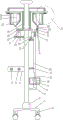
An injection rack for intelligently replacing a drip medicine bottle is disclosed, as shown in figures 1-3, and comprises a bottom plate 1, a universal wheel 2, a pillar 3, an installation block 4, a first button 5, a second button 6, a support rod 7, a frame body 8, a cam 9, a first motor 10, a slide bar 11, a cross bar 12, a slide sleeve 13, an installation plate 14, a second motor 15, a first gear 16, a second gear 17, a shaft sleeve 18, a rotary disc 19, a clamping mechanism, a fixed cutting sleeve 29 and a vertical plate 30, wherein the bottom of the bottom plate 1 is provided with the universal wheel 2, the middle of the top of the bottom plate 1 is provided with the pillar 3, the bottom plate 1 is connected with the pillar 3 in a welding connection mode, the lower part of the left side of the pillar 3 is provided with the installation block 4, the installation block 4 is provided with the first button 5 and the second button 6, the first button 5 is positioned at the right side of the second button 6, the lower part of the right side of the pillar 3 is provided with the support rod 7, the top of the support rod 7 is provided with the first motor 10, and the first motor 10 is electrically connected with the first button 5, a cam 9 is arranged on an output shaft at the front side of a first motor 10, a cross rod 12 is arranged at the upper part and the lower part on the right side of a strut 3, the strut 3 is connected with the cross rod 12 in a welding connection mode, a sliding sleeve 13 is arranged at the right side of the cross rod 12, a sliding rod 11 is arranged in the sliding sleeve 13 in a sliding mode, a frame body 8 is arranged at the bottom of the sliding rod 11, the cam 9 is positioned in the frame body 8, a mounting plate 14 is arranged at the upper part on the left side of the strut 3, a second motor 15 is arranged at the top of the mounting plate 14, the second motor 15 is electrically connected with a second button 6, a first gear 16 is arranged on an output shaft of the second motor 15, a shaft sleeve 18 is rotatably arranged at the outer side of the upper part of the strut 3, a second gear 17 is arranged at the bottom of the shaft sleeve 18, the first gear 16 is meshed with the second gear 17, the first gear 16 and the second gear 17 have a circumferential length ratio of 1: 6, a rotary table 19 is arranged at the upper part on the outer side of the shaft sleeve 18, the shaft sleeve 18 is connected with the rotary table 19 in a welding connection mode, six clamping mechanisms are uniformly spaced at the circumferential direction at the bottom of the rotary table 19, the upper part of the right side of the sliding rod 11 is provided with a vertical plate 30, and the right side of the vertical plate 30 is provided with a fixed cutting sleeve 29.
Example 2
An injection rack for intelligently replacing a drip medicine bottle is disclosed, as shown in figures 1-3, and comprises a bottom plate 1, a universal wheel 2, a pillar 3, an installation block 4, a first button 5, a second button 6, a support rod 7, a frame body 8, a cam 9, a first motor 10, a slide bar 11, a cross bar 12, a slide sleeve 13, an installation plate 14, a second motor 15, a first gear 16, a second gear 17, a shaft sleeve 18, a rotary disc 19, a clamping mechanism, a fixed cutting sleeve 29 and a vertical plate 30, wherein the bottom of the bottom plate 1 is provided with the universal wheel 2, the middle of the top of the bottom plate 1 is provided with the pillar 3, the left lower part of the pillar 3 is provided with the installation block 4, the installation block 4 is provided with the first button 5 and the second button 6, the first button 5 is positioned at the right side of the second button 6, the lower part of the right side of the pillar 3 is provided with the support rod 7, the top of the support rod 7 is provided with the first motor 10, the first motor 10 is electrically connected with the first button 5, the cam 9 is arranged at the front side of the first motor 10, the upper portion and the lower portion on the right side of a pillar 3 are respectively provided with a cross rod 12, the right side of the cross rod 12 is provided with a sliding sleeve 13, a sliding rod 11 is arranged in the sliding sleeve 13 in a sliding mode, the bottom of the sliding rod 11 is provided with a frame body 8, a cam 9 is located in the frame body 8, the upper portion on the left side of the pillar 3 is provided with a mounting plate 14, the top of the mounting plate 14 is provided with a second motor 15, the second motor 15 is electrically connected with a second button 6, an output shaft of the second motor 15 is provided with a first gear 16, the outer side of the upper portion of the pillar 3 is rotatably provided with a shaft sleeve 18, the bottom of the shaft sleeve 18 is provided with a second gear 17, the first gear 16 is meshed with the second gear 17, the circumferential length ratio of the first gear 16 to the second gear 17 is 1: 6, the upper portion on the outer side of the shaft sleeve 18 is provided with a rotating disc 19, the bottom of the rotating disc 19 is circumferentially and uniformly provided with six clamping mechanisms at intervals, the upper portion on the right side of the slide rod 11 is provided with a vertical plate 30, and the right side of the vertical plate 30 is provided with a fixed clamping sleeve 29.
Clamping mechanism is including slide rail 20, baffle 21, first spring 22, slider 23, activity splint 24 and solid fixed splint 27, six slide rails 20 and six solid fixed splint 27 set up the bottom circumference at carousel 19 evenly at intervals, slide rail 20 and solid fixed splint 27 all are connected with carousel 19 through welded connection's mode, the slide rail 20 outside is equipped with baffle 21, the last slip of slide rail 20 is equipped with slider 23, be equipped with first spring 22 between the slider 23 outside and the baffle 21 inboard, slider 23 bottom is equipped with activity splint 24, slider 23 is connected with activity splint 24 through welded connection's mode, activity splint 24 is located the solid fixed splint 27 outside.
Example 3
An injection rack for intelligently replacing a drip medicine bottle is disclosed, as shown in figures 1-3, and comprises a bottom plate 1, a universal wheel 2, a pillar 3, an installation block 4, a first button 5, a second button 6, a support rod 7, a frame body 8, a cam 9, a first motor 10, a slide bar 11, a cross bar 12, a slide sleeve 13, an installation plate 14, a second motor 15, a first gear 16, a second gear 17, a shaft sleeve 18, a rotary disc 19, a clamping mechanism, a fixed cutting sleeve 29 and a vertical plate 30, wherein the bottom of the bottom plate 1 is provided with the universal wheel 2, the middle of the top of the bottom plate 1 is provided with the pillar 3, the left lower part of the pillar 3 is provided with the installation block 4, the installation block 4 is provided with the first button 5 and the second button 6, the first button 5 is positioned at the right side of the second button 6, the lower part of the right side of the pillar 3 is provided with the support rod 7, the top of the support rod 7 is provided with the first motor 10, the first motor 10 is electrically connected with the first button 5, the cam 9 is arranged at the front side of the first motor 10, the upper portion and the lower portion on the right side of a pillar 3 are respectively provided with a cross rod 12, the right side of the cross rod 12 is provided with a sliding sleeve 13, a sliding rod 11 is arranged in the sliding sleeve 13 in a sliding mode, the bottom of the sliding rod 11 is provided with a frame body 8, a cam 9 is located in the frame body 8, the upper portion on the left side of the pillar 3 is provided with a mounting plate 14, the top of the mounting plate 14 is provided with a second motor 15, the second motor 15 is electrically connected with a second button 6, an output shaft of the second motor 15 is provided with a first gear 16, the outer side of the upper portion of the pillar 3 is rotatably provided with a shaft sleeve 18, the bottom of the shaft sleeve 18 is provided with a second gear 17, the first gear 16 is meshed with the second gear 17, the circumferential length ratio of the first gear 16 to the second gear 17 is 1: 6, the upper portion on the outer side of the shaft sleeve 18 is provided with a rotating disc 19, the bottom of the rotating disc 19 is circumferentially and uniformly provided with six clamping mechanisms at intervals, the upper portion on the right side of the slide rod 11 is provided with a vertical plate 30, and the right side of the vertical plate 30 is provided with a fixed clamping sleeve 29.
Clamping mechanism is including slide rail 20, baffle 21, first spring 22, slider 23, activity splint 24 and fixed splint 27, and six slide rails 20 and six fixed splint 27 set up in the bottom circumference of carousel 19 evenly at intervals, and the slide rail 20 outside is equipped with baffle 21, and the slide rail 20 is gone up the slip and is equipped with slider 23, is equipped with first spring 22 between the slider 23 outside and the baffle 21 inboard, and slider 23 bottom is equipped with activity splint 24, and activity splint 24 is located the fixed splint 27 outside.
The sliding rod structure is characterized by further comprising a circular block 31, a second spring 32, a third button 33, a pressing plate 34 and an L-shaped rod 35, the circular block 31 is arranged on the upper portion of the sliding rod 11, the L-shaped rod 35 is arranged on the left side of the circular block 31, the circular block 31 is connected with the L-shaped rod 35 in a welding connection mode, the pressing plate 34 is arranged at the bottom of the L-shaped rod 35, the L-shaped rod 35 is connected with the pressing plate 34 in a welding connection mode, the third button 33 is arranged at the top of the upper cross rod 12, the pressing plate 34 is located at the top of the third button 33, the second spring 32 is arranged between the bottom of the circular plate 36 and the top of the sliding sleeve 13, and the third button 33 is electrically connected with the second motor 15.
Example 4
An injection rack for intelligently replacing a drip medicine bottle is disclosed, as shown in figures 1-3, and comprises a bottom plate 1, a universal wheel 2, a pillar 3, an installation block 4, a first button 5, a second button 6, a support rod 7, a frame body 8, a cam 9, a first motor 10, a slide bar 11, a cross bar 12, a slide sleeve 13, an installation plate 14, a second motor 15, a first gear 16, a second gear 17, a shaft sleeve 18, a rotary disc 19, a clamping mechanism, a fixed cutting sleeve 29 and a vertical plate 30, wherein the bottom of the bottom plate 1 is provided with the universal wheel 2, the middle of the top of the bottom plate 1 is provided with the pillar 3, the left lower part of the pillar 3 is provided with the installation block 4, the installation block 4 is provided with the first button 5 and the second button 6, the first button 5 is positioned at the right side of the second button 6, the lower part of the right side of the pillar 3 is provided with the support rod 7, the top of the support rod 7 is provided with the first motor 10, the first motor 10 is electrically connected with the first button 5, the cam 9 is arranged at the front side of the first motor 10, the upper portion and the lower portion on the right side of a pillar 3 are respectively provided with a cross rod 12, the right side of the cross rod 12 is provided with a sliding sleeve 13, a sliding rod 11 is arranged in the sliding sleeve 13 in a sliding mode, the bottom of the sliding rod 11 is provided with a frame body 8, a cam 9 is located in the frame body 8, the upper portion on the left side of the pillar 3 is provided with a mounting plate 14, the top of the mounting plate 14 is provided with a second motor 15, the second motor 15 is electrically connected with a second button 6, an output shaft of the second motor 15 is provided with a first gear 16, the outer side of the upper portion of the pillar 3 is rotatably provided with a shaft sleeve 18, the bottom of the shaft sleeve 18 is provided with a second gear 17, the first gear 16 is meshed with the second gear 17, the circumferential length ratio of the first gear 16 to the second gear 17 is 1: 6, the upper portion on the outer side of the shaft sleeve 18 is provided with a rotating disc 19, the bottom of the rotating disc 19 is circumferentially and uniformly provided with six clamping mechanisms at intervals, the upper portion on the right side of the slide rod 11 is provided with a vertical plate 30, and the right side of the vertical plate 30 is provided with a fixed clamping sleeve 29.
Clamping mechanism is including slide rail 20, baffle 21, first spring 22, slider 23, activity splint 24 and fixed splint 27, and six slide rails 20 and six fixed splint 27 set up in the bottom circumference of carousel 19 evenly at intervals, and the slide rail 20 outside is equipped with baffle 21, and the slide rail 20 is gone up the slip and is equipped with slider 23, is equipped with first spring 22 between the slider 23 outside and the baffle 21 inboard, and slider 23 bottom is equipped with activity splint 24, and activity splint 24 is located the fixed splint 27 outside.
The sliding rod structure is characterized by further comprising a circular block 31, a second spring 32, a third button 33, a pressing plate 34 and an L-shaped rod 35, the circular block 31 is arranged on the upper portion of the sliding rod 11, the L-shaped rod 35 is arranged on the left side of the circular block 31, the pressing plate 34 is arranged at the bottom of the L-shaped rod 35, the third button 33 is arranged at the top of the upper cross rod 12, the pressing plate 34 is located at the top of the third button 33, the second spring 32 is arranged between the bottom of the circular plate 36 and the top of the sliding sleeve 13, and the third button 33 is electrically connected with the second motor 15.
The support column structure further comprises a circular plate 36 and number blocks 37, the circular plate 36 is arranged at the top of the rotary table 19, the rotary table 19 is connected with the circular plate 36 in a welding connection mode, the circular plate 36 penetrates through the top of the support column 3, six number blocks 37 are arranged on the outer side of the circular plate 36 in the circumferential direction at equal intervals, and sequential numbers from 1 to 6 are engraved on the six number blocks 37.
When the medical staff uses the device, the medicine bottle 25 to be injected is sequentially placed in the clamping mechanism, the medicine bottle 25 is clamped through the clamping mechanism, the head end of the disposable infusion apparatus is fixed through the fixing clamping sleeve 29, then the first button 5 is pressed, the first motor 10 rotates clockwise by 180 degrees, the first motor 10 rotates to drive the cam 9 to rotate clockwise by 180 degrees, the cam 9 rotates to drive the frame body 8 to move upwards, the frame body 8 moves upwards to drive the sliding rod 11 to move upwards, the sliding rod 11 moves upwards to drive the vertical plate 30 to move upwards, the vertical plate 30 moves upwards to drive the head end of the disposable injector 28 to be inserted into the medicine bottle 25 through the fixing clamping sleeve 29, then the patient is infused, when the liquid medicine in the medicine bottle 25 flows and needs to change the medicine bottle 25, the medical staff presses the first button 5 again, the first motor 10 is started to rotate, the first motor 10 rotates clockwise by 180 degrees again, the cam 9 rotates to drive the frame body 8 to move downwards, the frame body 8 moves downwards to drive the sliding rod 11 to move downwards, the sliding rod 11 moves downwards to pull out the head end of the disposable syringe 28 from the medicine bottle 25 through the fixed clamping sleeve 29, then the medical staff presses the second button 6 to start the second motor 15 to rotate for one circle, the second motor 15 rotates for one circle to drive the first gear 16 to rotate for one circle, because the circumferential length ratio of the first gear 16 to the second gear 17 is 1: 6, the first gear 16 drives the second gear 176 times, the shaft sleeve 18 and the rotary disc 19 rotate along with the second gear, another medicine bottle 25 to be injected is just above the head end of the disposable syringe 28, the first button 5 is pressed again to enable the first motor 10 to rotate clockwise for 90 degrees again, so that the head end of the disposable syringe 28 is inserted into the medicine bottle 25 above again, and thus the injection and medicine change can be completed without a nurse, the efficiency is improved.
When medical personnel need change medicine bottle 25, at first stimulate movable clamp plate 24 and outwards remove, movable clamp plate 24 outwards removes and drives slider 23 and outwards removes, and first spring 22 is compressed, and medical personnel place medicine bottle 25 at fixed splint 27 inboard this moment, and medical personnel loosen movable clamp plate 24 afterwards, because of taking slider 23 to inwards remove under the spring action of first spring 22, slider 23 inwards removes and drives movable clamp plate 24 and inwards remove and clip medicine bottle 25.
When the slide rod 11 moves upward, the circular block 31 is driven to move upward, the circular block 31 moves upward to drive the L-shaped rod 35 to move upward, the L-shaped rod 35 moves upward to drive the press plate 34 to move upward, the second spring 32 is reset, when the slide rod 11 moves downwards, the circular block 31 moves downwards along with the slide rod, the second spring 32 is compressed, the circular block 31 moves downwards to drive the L-shaped rod 35 to move downwards, the L-shaped rod 35 moves downwards to drive the pressing plate 34 to move downwards, the pressing plate 34 moves downwards to press the third button 33, the second motor 15 rotates one circle after the third button 33 is pressed, so that the first gear 16, the second gear 17 and the shaft sleeve 18 drive the rotating disc 19 to rotate, so that another medicine bottle 25 to be injected is positioned right above the head end of the disposable injector 28, therefore, the dressing change work can be automatically carried out only by controlling the first button 5, so that the operation of the dressing change machine is simpler and more intelligent.
Through the number on digital block 37, medical personnel fix medicine bottle 25 on clamping mechanism in proper order according to the injection order, and medical personnel can come to observe through digital block 37 that has used several bottles of medicine, makes patient or medical personnel know the process of injection more directly perceived.
The above-mentioned embodiments are merely preferred embodiments of the present invention, which are not intended to limit the scope of the present invention, and therefore, all equivalent changes made by the contents of the claims of the present invention should be included in the claims of the present invention.