CN110466752B - Control method of tilt rotor unmanned aerial vehicle and tilt rotor unmanned aerial vehicle - Google Patents
Control method of tilt rotor unmanned aerial vehicle and tilt rotor unmanned aerial vehicle Download PDFInfo
- Publication number
- CN110466752B CN110466752B CN201910727161.3A CN201910727161A CN110466752B CN 110466752 B CN110466752 B CN 110466752B CN 201910727161 A CN201910727161 A CN 201910727161A CN 110466752 B CN110466752 B CN 110466752B
- Authority
- CN
- China
- Prior art keywords
- unmanned aerial
- aerial vehicle
- motor
- power
- angle
- Prior art date
- Legal status (The legal status is an assumption and is not a legal conclusion. Google has not performed a legal analysis and makes no representation as to the accuracy of the status listed.)
- Active
Links
Images


Classifications
-
- B—PERFORMING OPERATIONS; TRANSPORTING
- B64—AIRCRAFT; AVIATION; COSMONAUTICS
- B64C—AEROPLANES; HELICOPTERS
- B64C27/00—Rotorcraft; Rotors peculiar thereto
- B64C27/22—Compound rotorcraft, i.e. aircraft using in flight the features of both aeroplane and rotorcraft
-
- B—PERFORMING OPERATIONS; TRANSPORTING
- B64—AIRCRAFT; AVIATION; COSMONAUTICS
- B64C—AEROPLANES; HELICOPTERS
- B64C27/00—Rotorcraft; Rotors peculiar thereto
- B64C27/32—Rotors
- B64C27/46—Blades
- B64C27/473—Constructional features
- B64C27/50—Blades foldable to facilitate stowage of aircraft
-
- B—PERFORMING OPERATIONS; TRANSPORTING
- B64—AIRCRAFT; AVIATION; COSMONAUTICS
- B64C—AEROPLANES; HELICOPTERS
- B64C27/00—Rotorcraft; Rotors peculiar thereto
- B64C27/52—Tilting of rotor bodily relative to fuselage
-
- B—PERFORMING OPERATIONS; TRANSPORTING
- B64—AIRCRAFT; AVIATION; COSMONAUTICS
- B64C—AEROPLANES; HELICOPTERS
- B64C39/00—Aircraft not otherwise provided for
- B64C39/02—Aircraft not otherwise provided for characterised by special use
-
- B—PERFORMING OPERATIONS; TRANSPORTING
- B64—AIRCRAFT; AVIATION; COSMONAUTICS
- B64D—EQUIPMENT FOR FITTING IN OR TO AIRCRAFT; FLIGHT SUITS; PARACHUTES; ARRANGEMENT OR MOUNTING OF POWER PLANTS OR PROPULSION TRANSMISSIONS IN AIRCRAFT
- B64D27/00—Arrangement or mounting of power plants in aircraft; Aircraft characterised by the type or position of power plants
- B64D27/02—Aircraft characterised by the type or position of power plants
- B64D27/24—Aircraft characterised by the type or position of power plants using steam or spring force
Landscapes
- Engineering & Computer Science (AREA)
- Aviation & Aerospace Engineering (AREA)
- Mechanical Engineering (AREA)
- Toys (AREA)
- Control Of Position, Course, Altitude, Or Attitude Of Moving Bodies (AREA)
Abstract
The invention provides a control method of a tilt rotor unmanned aerial vehicle and the tilt rotor unmanned aerial vehicle, the tilt rotor unmanned aerial vehicle at least comprises: two sets of driving systems, first driving system include two power device that are located aircraft nose and tail respectively, and second driving system of group includes two power device that are located the fuselage both sides, and power device includes motor and screw, and this rotor unmanned aerial vehicle verts's control method includes: judging the flight mode of the unmanned aerial vehicle according to the user instruction; according to the flight data and the flight mode of the unmanned aerial vehicle, the rotating speed of a motor of the power device and/or the angle of a propeller are/is adjusted. According to the embodiment of the invention, the rotating speed and variable inclination angle control of each power system are comprehensively controlled, so that the response time of the power systems is reduced, and the stability and reliability of the unmanned aerial vehicle body are improved.
Description
Technical Field
The invention relates to the technical field of unmanned aerial vehicles, in particular to a control method of a tilt rotor unmanned aerial vehicle and the tilt rotor unmanned aerial vehicle.
Background
Common unmanned aerial vehicle aircraft is mostly many rotors and fixed wing structure, and wherein, many rotors advantage does not receive geographical position constraint can realize VTOL, control flexibility, stability is higher and can keep hovering for a long time, and the shortcoming lies in that the flying speed is lower, the time of endurance leads to the working range little for a short time. And the flight time of the fixed wing is relatively just long a lot compared with many rotors, and flying speed is also very big, consequently takes into account many rotor unmanned aerial vehicle's shortcoming, but does not possess advantages such as many rotor unmanned aerial vehicle's VTOL, accurate hover.
Along with the development of unmanned aerial vehicle technique, this kind of advantage that can carry out many rotors and fixed wing unmanned aerial vehicle of rotor unmanned aerial vehicle that verts carries out limited combination, realizes can VTOL and guarantee again can high-speed cruise when accurate hovering. However, because the unmanned aerial vehicle with tilt rotor is bigger because the volume is bigger, and the inertia of organism is great, therefore only when the rotational speed difference through traditional motor realizes VTOL, suspension, the stability and the reliability of unmanned aerial vehicle fuselage receive the influence.
Present rotor unmanned aerial vehicle that verts is all not ideal at the switching of many rotor working modes and stationary vane working mode, for example the rotor unmanned aerial vehicle that verts of "4 + 1" mode adopts 4 sets of perpendicular power device and one set of thrust device, and the driving system variable pitch angle of wing both sides is synchronous, and non-independent adjustment is not nimble enough, and stability is not good enough. For example, the rotor unmanned aerial vehicle that verts of "2 + 2" mode again, this kind of overall arrangement adopts 4 power device of both sides distribution around the main wing, and when power device and fuselage horizontal work, the screw can produce the reaction force to the main wing, and then increases the degree of difficulty for unmanned aerial vehicle keeps the stability of fuselage. Other types of tilt rotor unmanned aerial vehicle also all face the problem that stability is not good when unmanned aerial vehicle flies, and control is not flexible enough.
So how can adjust unmanned aerial vehicle's gesture in short time to can make the rotor unmanned aerial vehicle that verts of heavy weight remain stable again, realize accurate control, be the problem that awaits the solution urgently.
Disclosure of Invention
The embodiment of the invention provides a control method of a tilt rotor unmanned aerial vehicle and the tilt rotor unmanned aerial vehicle, and aims to solve the problem that the control method of the tilt rotor unmanned aerial vehicle in the prior art is difficult to adjust the posture of the unmanned aerial vehicle in a short time and keep the stability of the unmanned aerial vehicle body.
The embodiment of the invention provides a control method of a tilt rotor unmanned aerial vehicle, which at least comprises the following steps: the method comprises the following steps of: judging the flight mode of the unmanned aerial vehicle according to a user instruction; according to the flight data and the flight mode of the unmanned aerial vehicle, the rotating speed of a motor of the power device and/or the angle of the propeller are adjusted, or the rotating speed of the motor and the angle of the propeller are adjusted simultaneously, so that the unmanned aerial vehicle completes the user instruction in the flight mode.
Optionally, according to user's instruction, judge tilt rotor unmanned aerial vehicle's flight mode includes: judging whether the unmanned aerial vehicle is in a cruising operation stage or not according to the user instruction; if so, the flight mode of the unmanned aerial vehicle is a fixed wing mode, and if not, the flight mode of the unmanned aerial vehicle is a multi-rotor mode.
Optionally, the fixed-wing mode refers to: the angles of the propellers of the two groups of power systems are parallel, the motor of the first group of power systems rotates, the motor of the second group of power systems stops, and the user instruction is completed by adjusting the wings of the tilt rotor unmanned aerial vehicle; wherein, parallel, mean the rotatory direction of force that produces of screw with the plane parallel at fuselage and main wing place, and tilt rotor unmanned aerial vehicle's wing includes at least: a main wing, an aileron, and a tail wing.
Optionally, the multi-rotor mode is: when the unmanned aerial vehicle is in a hovering stage, the angles of the propellers of the two groups of power systems are vertical, and the motors of the two groups of power systems rotate; when the unmanned aerial vehicle is in a take-off and landing movement stage, adjusting the angles of the propellers of the two groups of power systems on a vertical basis, or adjusting the rotating speed of a motor of the power device, or adjusting the angles of the propellers and the rotating speed of the motor simultaneously to complete the user instruction; the vertical direction means that the direction of the force generated by the rotation of the propeller is vertical to the plane of the main wing and the body.
Optionally, the flight data of the drone includes: the rotational speed of power device's motor and the angle of screw, and rotor unmanned aerial vehicle's that verts attitude angle.
Optionally, the adjusting, according to the flight data of the unmanned aerial vehicle, the rotation speed of the motor of the power device and/or the angle of the propeller, or both the rotation speed of the motor and the angle of the propeller, so that the unmanned aerial vehicle completes the user instruction in the flight mode includes: judging whether the attitude angle meets a preset variable inclination angle condition or not; if so, adjusting the angle of the propeller, or simultaneously adjusting the angle of the propeller and the rotating speed of the motor to reach a rotating speed difference so as to complete the user instruction; if not, only adjusting the rotating speed of the motor to reach the rotating speed difference so as to complete the user instruction.
Optionally, the adjusting, according to flight data of the unmanned aerial vehicle, a rotation speed of a motor of the power device and an angle of the propeller so that the unmanned aerial vehicle completes the user instruction in the flight mode includes: and according to the flight data of the unmanned aerial vehicle, independently adjusting the rotating speed of a motor of each power device and/or the angle of the propeller, so that the unmanned aerial vehicle completes the user instruction in the flight mode.
The embodiment of the invention also provides a tilt rotor unmanned aerial vehicle, which comprises: the airplane body comprises an airplane body, main wings arranged on two sides of the airplane body, and an airplane head and an airplane tail which are respectively arranged at the front end and the rear end of the airplane body; the first group of power systems comprise a power device positioned at the machine head and a power device positioned at the machine tail respectively, and the second group of power systems comprise a power device positioned at one side of the machine body and a power device positioned at the other side of the machine body, wherein each power device comprises a motor and a propeller, and each power device is used for changing the magnitude of the generated force by adjusting the rotating speed of the motor and changing the direction of the generated force by adjusting the angle of the propeller; and the control system is arranged in the body and comprises a memory and a processor, and the processor executes the computer instructions stored in the memory so as to execute the tilt rotor unmanned aerial vehicle control method in another embodiment of the invention and any optional implementation manner thereof.
Optionally, the body further comprises: the ailerons are arranged on two sides of the main wing and the tail wing is arranged at the tail.
Optionally, the power device and the power device are arranged on the body and behind the main wing.
The technical scheme of the invention has the following advantages:
1. the embodiment of the invention provides a control method of a tilt rotor unmanned aerial vehicle, which reduces the influence of self inertia on a machine body, reduces the response time of a power system and increases the stability and flexibility of the unmanned aerial vehicle in the flying process by comprehensively controlling the rotating speed and the variable inclination angle of each power system when the unmanned aerial vehicle needs to change the flying stage rapidly.
2. The embodiment of the invention provides a tilt rotor unmanned aerial vehicle, which is provided with a special power system layout, so that the unmanned aerial vehicle can rapidly change the flight stage of the tilt rotor unmanned aerial vehicle by comprehensively controlling the rotating speed and the variable inclination angle of each power system, the mutual influence between the tilt rotor and a fixed wing is reduced, the influence that the large-mass unmanned aerial vehicle has larger self inertia and is difficult to change in posture is weakened, the response time of the power system is shortened, and the stability and the flexibility of the unmanned aerial vehicle body are improved.
Drawings
In order to more clearly illustrate the embodiments of the present invention or the technical solutions in the prior art, the drawings used in the description of the embodiments or the prior art will be briefly described below, and it is obvious that the drawings in the following description are some embodiments of the present invention, and other drawings can be obtained by those skilled in the art without creative efforts.
Fig. 1A is a block diagram of a tilt rotor drone in an embodiment of the present invention;
fig. 1B is a schematic view of a tilt rotor drone in a fixed wing mode in accordance with an embodiment of the present invention;
fig. 1C is a schematic view of a tilt rotor drone in a multi-rotor mode in accordance with an embodiment of the present invention;
fig. 2 is a flowchart of a method for controlling a tiltrotor unmanned aerial vehicle in an embodiment of the invention;
fig. 3 is a schematic diagram of a control system of a tiltrotor drone in an embodiment of the present invention.
Detailed Description
The technical solutions of the present invention will be described clearly and completely with reference to the accompanying drawings, and it should be understood that the described embodiments are some, but not all embodiments of the present invention. All other embodiments, which can be derived by a person skilled in the art from the embodiments given herein without making any creative effort, shall fall within the protection scope of the present invention.
In the description of the present invention, it should be noted that the terms "center", "upper", "lower", "left", "right", "vertical", "horizontal", "inner", "outer", etc., indicate orientations or positional relationships based on the orientations or positional relationships shown in the drawings, and are only for convenience of description and simplicity of description, but do not indicate or imply that the device or element being referred to must have a particular orientation, be constructed and operated in a particular orientation, and thus, should not be construed as limiting the present invention. Furthermore, the terms "first," "second," and "third" are used for descriptive purposes only and are not to be construed as indicating or implying relative importance.
In the description of the present invention, it should be noted that, unless otherwise explicitly specified or limited, the terms "mounted," "connected," and "connected" are to be construed broadly, e.g., as meaning either a fixed connection, a removable connection, or an integral connection; can be mechanically or electrically connected; the two elements may be directly connected or indirectly connected through an intermediate medium, or may be communicated with each other inside the two elements, or may be wirelessly connected or wired connected. The specific meanings of the above terms in the present invention can be understood in specific cases to those skilled in the art.
In addition, the technical features involved in the different embodiments of the present invention described below may be combined with each other as long as they do not conflict with each other.
Example 1
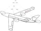
Fig. 1A shows a structural diagram of a tilt rotor drone provided by an embodiment of the present invention. Rotor unmanned aerial vehicle verts includes: a machine body 101, two sets of power systems 102 and 103 provided on the machine body 101, and a control system 104 (not shown) provided inside the machine body 101.
Specifically, the airframe 101 includes a fuselage 1011, main wings 1012 disposed on both sides of the fuselage 1011, and a nose 1013 and a tail 1014 disposed at front and rear ends of the fuselage 1011, respectively;
two groups of power systems, wherein the first group of power system 102 comprises a power device 1021 of a machine head 1013 and a power device 1022 of a machine tail 1014 respectively, the second group of power system 103 comprises a power device 1023 of one side of a machine body 1011 and a power device 1024 of the other side, wherein each of the power devices 1021 and 1024 comprises a motor and a propeller, and each of the power devices 1021 and 1024 is used for changing the magnitude of the generated force by adjusting the rotating speed of the motor and changing the direction of the generated force by adjusting the angle of the propeller; and
control system 104, inside control system 104 located organism 101, including memory and treater, the computer instruction that the treater was through carrying out storage in the memory for control unmanned aerial vehicle's flight.
In one embodiment of the invention, the rotation speed of the motor and the angle of the propeller of each power device of the power system of the tilt rotor unmanned aerial vehicle are adjusted independently of each other. This kind of independent adjustment makes unmanned aerial vehicle's power device more nimble, and is quicker to the response of user's instruction. No matter change the direction of force through the mode of becoming the inclination or change unmanned aerial vehicle's atress through the mode of motor speed difference and change unmanned aerial vehicle's flight state, all reach the flight of controlling unmanned aerial vehicle more stably and in a flexible way.
In an embodiment of the present invention, the body 101 further includes: ailerons 1015 disposed on both sides of the main wing 1012 and a tail 1016 disposed on the tail 1014.
In one embodiment of the present invention, the power device 1023 and the power device 1024 are disposed on the body 101 behind the main wing 1012.
In one embodiment of the invention, a tilt rotor drone has two flight modes: multi-rotor mode and fixed-wing mode. When the tilt rotor unmanned aerial vehicle is in the stage of ascending, descending or hovering, the unmanned aerial vehicle works in a multi-rotor mode. When rotor unmanned aerial vehicle verts is in the operation stage that cruises, unmanned aerial vehicle works under the fixed wing mode.
Wherein the unmanned aerial vehicle state in fixed wing mode is as shown in fig. 1B. In the fixed wing mode, the angles of the propellers of the two power systems 102 and 103 are parallel, the motors of the two power devices 1021, 1022 of the first power system 102 rotate, and the motors of the two power devices 1023, 1024 of the second power system 103 stop, and the user command, i.e. the cruise mission, is accomplished by adjusting the main wing 1012, the ailerons 1015 on both sides, and the tail 1016 of the tiltrotor drone. Here, the parallel means that the direction of the force generated by the rotation of the propeller is parallel to the plane where the main body 1011 and the main wing 1012 are located. In the cruising operation stage, the stress of the unmanned aerial vehicle in the vertical direction meets the condition that Y-G is more than or equal to 0, wherein Y is the lift force of the wing (Y is in direct proportion to the lift force coefficient, the wing area, the speed of the unmanned aerial vehicle, the atmospheric density and the like), and G is the self gravity of the unmanned aerial vehicle. Therefore, the propellers of the power system 102 generate horizontal pushing force and pulling force, so that the unmanned aerial vehicle only provides upward force by the wings in the cruising operation stage; the propeller of the power system 103 is stowed in a vertical orientation with as little influence from the propeller as possible.
Wherein the drone state in the multi-rotor mode is as shown in figure 1C. The state of the drone in the multi-rotor mode is described in detail below:
1. in the hovering phase, the angles of the propellers of all the power plants of both sets of power systems 102 and 103 are vertical. Here, the vertical direction means that the direction of the force generated by the rotation of the propeller is perpendicular to the plane where the main body 1011 and the main wing 1012 are located. In this case, for example, the four power devices 1021 and 1024 of the two sets of power systems 102 and 103 operate in the same manner and principle as the rotor of the prior art rotary-wing drone.
2. In the lifting and moving stage, the angles of the propellers of all the power devices 1021 and 1024 of the two groups of power systems 102 and 103 are adjusted on a vertical basis, or the rotating speeds of the motors of the power devices 1021 and 1024 are adjusted to reach a rotating speed difference, or the angles of the propellers and the rotating speeds of the motors are adjusted at the same time, so as to complete user instructions on lifting and moving.
In one embodiment of the invention, drone control system 104 determines the mode of flight of the drone according to user instructions.
The control system 104 is configured to determine whether the user instruction instructs the unmanned aerial vehicle to enter a cruise operation stage, and if so, determine that a flight mode of the unmanned aerial vehicle is a fixed wing mode; if not, the flight mode of the unmanned aerial vehicle is judged to be a multi-rotor mode.
Wherein, the user command is sent from the user control terminal to be received by the receiving end of the unmanned aerial vehicle and send the relevant data to the control system 104.
In an embodiment of the present invention, the control system 104 is configured to adjust the rotation speed of the motor and the angle of the propeller of the power device 1021 and 1024 according to the flight data of the drone, so that the drone completes the user command in the flight mode.
Wherein, unmanned aerial vehicle's flight data includes: the power device 1021 along with the rotation speed of the 1024 motor and the angle of the propeller, and the attitude angle of the tilt rotor unmanned aerial vehicle.
Wherein the attitude angle of the drone is obtained by an Inertial Measurement Unit (IMU) in the control system 104.
In an embodiment of the present invention, the control system 104 is configured to adjust the rotation speed of the motor of the power device and the angle of the propeller according to the flight data of the drone, so that the drone completes the user command in the flight mode, and includes: judging whether the attitude angle meets a preset variable inclination angle condition or not; if so, adjusting the angle of the propeller, or simultaneously adjusting the angle of the propeller and the rotating speed of the motor to reach a rotating speed difference so as to complete a user instruction; if not, only adjusting the rotating speed of the motor to reach the rotating speed difference so as to complete the user instruction.
The preset variable inclination angle condition is a preset condition of an attitude angle of the unmanned aerial vehicle, and if the preset variable inclination angle condition is met, the state of the unmanned aerial vehicle is changed in a variable inclination angle mode, namely a mode of changing the angle of a propeller; if the condition is not met, the state of the unmanned aerial vehicle is changed only by means of differential speed instead of using a mode of changing the angle of the propeller. For example, if the preset variable inclination condition is satisfied that the pitch axis (pitch) of the attitude angle is greater than 10 °, when it is detected that the attitude angle of the drone is greater than 10 ° at the pitch axis, a method of adjusting the angle of the propeller of the power plant is taken. Since changing the angle of the propeller will quickly change the direction of the force, this can directly change the state of the drone; the magnitude of the force in different directions can be changed only by changing the rotating speed difference, but under the condition that the self mass of the unmanned aerial vehicle is large, the response time of the unmanned aerial vehicle is long, and the effect of the desired flight state of the unmanned aerial vehicle cannot be achieved even under the condition of long response time, so the invention provides a mode of adjusting the angles of the propellers of the power device 1021 and the 1024, or a mode of simultaneously adjusting the combination of the angles of the propellers and the rotating speed of the motor, so as to respond more quickly and more stably.
Wherein, motor speed and the screw angle to each driving system of unmanned aerial vehicle carry out the independent control, have guaranteed the flexibility of each part for control is convenient more quick.
Wherein the angle of the propeller can be adjusted by a tilting mechanism installed in the power unit.
The specific adjustment, the rotation speed difference and the inclination angle adjustment are calculated and controlled by the unmanned aerial vehicle control system 104 with a calculation function according to a preset algorithm. On the contrary, if the preset variable inclination angle condition is not met (for example, the preset variable inclination angle condition is that the pitch axis is greater than 10 degrees, and the detected attitude angle pitch axis of the unmanned aerial vehicle is less than 10 degrees), the state of the unmanned aerial vehicle can be changed by only adopting a method of adjusting the rotating speed of the motor of the power device 1021 and 1024. The above is merely an example, and the preset variable inclination angle condition can be set according to actual conditions, and is not limited to the pitch axis, nor to a specific angle.
In another embodiment of the present invention, when the two flight modes are switched to each other, specifically, from the multi-rotor mode to the fixed-wing mode (for example, during the taking off and landing or hovering phase, cruise operation is to be entered), or from the fixed-wing mode to the multi-rotor mode (for example, during the cruising phase, taking off and landing or hovering are required), the above steps are also required, and the flight mode of the drone is determined according to the user instruction; according to the flight data of the unmanned aerial vehicle, the rotating speed of the motor or the angle of the propeller is adjusted through the preset attitude angle, the rotating speed of the motor and the angle of the propeller, or the rotating speed of the motor and the angle of the propeller are adjusted simultaneously through the power device 1021 and the 1024, and the switching of the flight modes is achieved.
The embodiment of the invention adopts a conventional rotor power layout mode, namely a '+' layout, in order to reduce the influence of the reaction force of the airframe on the stability of the unmanned aerial vehicle, two power systems are respectively arranged at the positions of the nose and the tail, and the other two power systems are arranged at the rear part of the main wing. In the taking-off and landing stage, the four power devices of the unmanned aerial vehicle are all adjusted to be vertical through the tilting structures, and the flight control system controls the rotating speeds of the four power devices and the angles of the propellers simultaneously to realize the stable taking-off and landing, hovering and other work of the unmanned aerial vehicle; when the unmanned aerial vehicle enters into cruise, the unmanned aerial vehicle mainly relies on two power systems of the nose and the tail to provide power, and the main wing provides certain lift force, so that large-area operation with long voyage and high speed is finally realized.
In another embodiment of the present invention, the rotational speed of the motor and the angle of the propeller of each of the power devices 1021 through 1024 are individually controlled by the control system 104.
Example 2
Fig. 2 illustrates a control method of a tilt rotor drone according to an embodiment of the present invention. Tilt rotor unmanned aerial vehicle includes at least: two sets of power systems, first group power system include two power devices that are located aircraft nose and tail respectively, and second group power system includes two power devices that are located the fuselage both sides, and power device includes motor and screw, and the method includes:
step S201: judging the flight mode of the unmanned aerial vehicle according to the user instruction;
wherein, receive the user instruction from control terminal by the receiving terminal on the unmanned aerial vehicle. The user instructions include: take-off instructions, left and right instructions, descent instructions, hover instructions, cruise instructions, job instructions, and the like.
In one embodiment of the present invention, step S201 further includes:
step S2011, judging whether the unmanned aerial vehicle is in a cruising operation stage according to a user instruction;
if so, the method proceeds to step S2012: the flight mode of the unmanned aerial vehicle is a fixed wing mode, if not, the method proceeds to step S2013: the flight mode of the drone is a multi-rotor mode.
In one embodiment of the present invention, the fixed wing mode refers to: the angles of the propellers of the two groups of power systems are parallel, the motor of the first group of power systems rotates, the motor of the second group of power systems stops, and the user instruction is completed by adjusting the wings of the tilt rotor unmanned aerial vehicle; wherein, parallel, it is parallel with the plane at fuselage and main wing place to indicate the rotatory direction of force that produces of screw to and tilt rotor unmanned aerial vehicle's wing includes at least: a main wing, an aileron, and a tail wing.
Wherein, during the cruise operation phase, the drone enters a fixed-wing mode. At the moment, the rotating propeller generates horizontal thrust and pull force, so that the unmanned aerial vehicle only provides upward force by the wings of the unmanned aerial vehicle in the cruise operation stage; the stopped propeller is retracted and the arrangement is such that it is influenced as little as possible by the propeller in the vertical direction. Under the fixed wing mode, rotor unmanned aerial vehicle operating condition that verts is the same with fixed wing unmanned aerial vehicle.
In one embodiment of the invention, the multi-rotor mode refers to: when the unmanned aerial vehicle is in a hovering stage, the angles of the propellers of the two groups of power systems are vertical, and the motors of the two groups of power systems rotate; when the unmanned aerial vehicle is in a take-off and landing movement stage, adjusting the angles of the propellers of the two groups of power systems on a vertical basis according to flight data of the unmanned aerial vehicle, or adjusting the rotating speed of a motor of a power device, or adjusting the angles of the propellers and the rotating speed of the motor simultaneously to complete a user instruction; wherein, vertical means that the direction of the force generated by the rotation of the propeller is vertical to the plane of the main wing and the body.
Step S202: adjusting the rotating speed of a motor of a power device and/or the angle of a propeller according to the flight data and the flight mode of the unmanned aerial vehicle;
in one embodiment of the invention, the flight data of the drone comprises at least: the rotational speed of power device's motor and the angle of screw to and rotor unmanned aerial vehicle's that verts attitude angle.
Wherein, tiltrotor unmanned aerial vehicle's attitude angle information is obtained by unmanned aerial vehicle's own Inertial Measurement Unit (IMU).
Wherein, unmanned aerial vehicle removes and hovers the stage at take-off and land, not only adopts traditional many rotors to realize stable flight through the rotational speed difference of controlling dynamic system, has still combined the mode that becomes the inclination in step and has realized unmanned aerial vehicle flight control, has finally guaranteed that whole unmanned aerial vehicle is reliable, the most stable flight. And the attitude angle is used for calculating the magnitude of the rotating speed difference and the angle of the inclination angle so as to change the stress magnitude and direction of the unmanned aerial vehicle.
In an embodiment of the present invention, step S202 further includes:
s2021: judging whether the attitude angle meets a preset variable inclination angle condition or not;
if so, the method proceeds to step S2022: adjusting the angle of the propeller, or adjusting the angle of the propeller and the rotating speed of the motor to reach a rotating speed difference at the same time so as to complete a user instruction;
if not, the method proceeds to step S2023: only the rotating speed of the motor is adjusted to reach the rotating speed difference so as to complete the user instruction.
Wherein, the preset condition of becoming the inclination is the preset condition of unmanned aerial vehicle attitude angle, if satisfy this condition, then adopt the mode of becoming the inclination, change the mode of the angle of screw promptly and change the unmanned aerial vehicle state.
For example, if the preset variable inclination angle condition is met, namely that the pitch axis of the attitude angle is greater than 10 °, when the attitude angle of the unmanned aerial vehicle is detected to be greater than 10 ° on the pitch axis, a method for adjusting the angle of the propeller of the power device is adopted. Because the stress direction can be changed by changing the angle of the propeller, the state of the unmanned aerial vehicle can be changed at the fastest speed, and if the force in different directions is changed by only changing the rotating speed difference, under the condition that the self mass of the unmanned aerial vehicle is large, the response time is long, and the effect of the desired flight state of the unmanned aerial vehicle cannot be achieved even under the condition of long response time. Similarly, the combination of adjusting the angle of the propeller of the power device and adjusting the rotation speed of the motor of the power device can be adopted, so that the response is quicker and smoother. The specific adjustment, the rotation speed difference and the inclination angle adjustment are calculated and controlled by an unmanned aerial vehicle control system with a calculation function according to a preset algorithm.
On the contrary, if the preset variable inclination angle condition is met, the attitude angle pitch axis is larger than 10 degrees, and when the detected attitude angle pitch axis of the unmanned aerial vehicle is smaller than 10 degrees, the preset variable inclination angle condition is not met, and only the method for adjusting the rotating speed of the motor of the power device is adopted. This is merely an example, and the preset variable tilt angle condition may be set according to actual circumstances, and is not limited to the pitch axis, nor to the angle 10 °.
In one embodiment of the invention, the rotation speed of the motor and/or the angle of the propeller of each power device are independently adjusted according to the flight data of the unmanned aerial vehicle, so that the unmanned aerial vehicle can complete the user instruction in the flight mode.
Wherein, motor speed and the screw angle to each driving system of unmanned aerial vehicle carry out the independent control, have guaranteed the flexibility of each part for control is convenient more quick.
According to the control method of the tilt rotor unmanned aerial vehicle provided by the embodiment of the invention, by comprehensively controlling the rotating speed and the variable inclination angle of each power system, when the unmanned aerial vehicle is in a take-off and landing stage or a hovering stage, the influence of self inertia on the body is reduced, the response time of the power system is reduced, the stability and the reliability of the unmanned aerial vehicle body are increased, the control capability of the tilt rotor unmanned aerial vehicle can be improved, the flexibility of an unmanned aerial vehicle control system is enhanced, the maneuverability of the unmanned aerial vehicle control system is improved, the response speed of the control system is ensured, good stability can be still maintained when the flight mode of the unmanned aerial vehicle is changed, and the overall safety performance of the control system is improved.
Example 3
Fig. 3 illustrates a control system 104 for a tiltrotor drone, according to an embodiment of the present invention. This tilt rotor unmanned aerial vehicle's control system 104 includes: a tilter system 1041 and a flight control system 1042.
The tilting system 1041 comprises a memory and a processor, and the processor executes computer instructions stored in the memory, so as to be used for separately controlling the power inclination angles of each power system of the unmanned aerial vehicle, namely, the variable inclination angles, so that the advantage of separate control is that the stability of the unmanned aerial vehicle can be maintained with maximum efficiency, power balance can be maintained by controlling the inclination angles of the power systems in the stage of taking off and landing, and the high efficiency, safety and reliability of the system can be realized; while
Wherein, flight control system 1042 includes memory and treater, the computer instruction that the treater was through carrying out storage in the memory, thereby be used for controlling the rotational speed of the motor of each driving system to unmanned aerial vehicle, adopt redundancy regulation and control design, thereby make unmanned aerial vehicle at VTOL, when hovering, not only adopt traditional many rotors to realize stable flight through the rotational speed difference of controlling driving system, still the control mode that has combined the helicopter in step promptly the above-mentioned variable inclination has further strengthened control system's stability, the final flight that has guaranteed entire system is most reliable, most stable.
Through the cooperative cooperation of the components, the control system of the tilt rotor unmanned aerial vehicle provided by the embodiment of the invention judges the flight mode of the unmanned aerial vehicle according to the user instruction; according to unmanned aerial vehicle's flight data, the rotational speed of adjustment power device's motor, or the angle of screw, or the rotational speed of adjusting the motor simultaneously and the angle of screw for unmanned aerial vehicle accomplishes the user instruction under flight mode. Thereby the rotational speed through each driving system of integrated control with become the inclination and control, when unmanned aerial vehicle is in the stage of taking off and land or hover the stage, reduced the organism and received self inertial influence, thereby improve driving system's response time and increased the stability and the reliability of unmanned aerial vehicle fuselage, and can improve the unmanned aerial vehicle's that verts control capability, the flexibility of reinforcing system, improve the mobility of system, guarantee the response speed of system, still can keep fine stability when unmanned aerial vehicle flight mode changes, the holistic security performance of improvement system. And through the layout mode of each power system in the implementation of the invention, the influence of the disturbed flow of the propeller on the unmanned aerial vehicle body when the unmanned aerial vehicle takes off and lands or hovers can be reduced, the safety of the system is ensured from the aspect of structural layout, good stability can still be kept when the flight mode of the unmanned aerial vehicle changes, the overall safety performance of the unmanned aerial vehicle is improved, the mutual influence between the fixed-wing body and the multiple rotors can be reduced as little as possible, the influence of the reaction force of the body on the flight mode of the rotors is reduced, and the stability and the reliability of the system are ensured.
It should be understood that the above examples are only for clarity of illustration and are not intended to limit the embodiments. Other variations and modifications will be apparent to persons skilled in the art in light of the above description. And are neither required nor exhaustive of all embodiments. And obvious variations or modifications therefrom are within the scope of the invention.
Claims (8)
1. A control method for a tilt rotor unmanned aerial vehicle, the tilt rotor unmanned aerial vehicle comprising at least: the method comprises the following steps of:
judging the flight mode of the unmanned aerial vehicle according to a user instruction;
adjusting the rotating speed of a motor of the power device and/or the angle of the propeller according to the flight data and the flight mode of the unmanned aerial vehicle;
the flight data of the unmanned aerial vehicle comprises:
the rotating speed of a motor of the power device, the angle of a propeller and the attitude angle of the tilt rotor unmanned aerial vehicle are controlled by the control system;
according to unmanned aerial vehicle's flight data, adjust the rotational speed of power device's motor and/or the angle of screw, include:
judging whether the attitude angle meets a preset variable inclination angle condition or not;
if so, adjusting the angle of the propeller, or simultaneously adjusting the angle of the propeller and the rotating speed of the motor to reach a rotating speed difference so as to complete the user instruction;
if not, only adjusting the rotating speed of the motor to reach the rotating speed difference so as to complete the user instruction.
2. The method of claim 1, wherein said determining a flight mode of said tilt-rotor drone based on user instructions comprises:
judging whether the unmanned aerial vehicle is in a cruising operation stage or not according to the user instruction;
if so, then the mode of flight of the drone is a fixed-wing mode, and
if not, the flight mode of the unmanned aerial vehicle is a multi-rotor mode.
3. The method of claim 2, wherein the fixed-wing mode is:
the angles of the propellers of the two groups of power systems are parallel, the motor of the first group of power systems rotates, the motor of the second group of power systems stops, and the user instruction is completed by adjusting the wings of the tilt rotor unmanned aerial vehicle;
wherein, the parallel means that the direction of the force generated by the rotation of the propeller is parallel to the plane of the main wing and the fuselage, and
tilt rotor unmanned aerial vehicle's wing includes at least: a main wing, an aileron, and a tail wing.
4. The method of claim 3, wherein the multi-rotor mode is:
when the unmanned aerial vehicle is in a hovering stage, the angles of the propellers of the two groups of power systems are vertical, and the motors of the two groups of power systems rotate; and
when the unmanned aerial vehicle is in a take-off and landing movement stage, adjusting the angles of the propellers of the two groups of power systems on a vertical basis, or adjusting the rotating speed of a motor of the power device, or adjusting the angles of the propellers and the rotating speed of the motor simultaneously to complete the user instruction;
the vertical direction means that the direction of the force generated by the rotation of the propeller is vertical to the plane of the main wing and the body.
5. The method of any one of claims 1-4, wherein said adjusting a rotational speed of a motor of said power plant and an angle of said propeller according to flight data of said drone such that said drone completes said user command in said flight mode comprises:
and according to the flight data of the unmanned aerial vehicle, independently adjusting the rotating speed of a motor of each power device and/or the angle of the propeller, so that the unmanned aerial vehicle completes the user instruction in the flight mode.
6. The utility model provides a rotor unmanned aerial vehicle verts which characterized in that includes:
the airplane body (101) comprises an airplane body (1011), main wings (1012) arranged on two sides of the airplane body (1011), and a nose (1013) and a tail (1014) which are respectively arranged at the front end and the rear end of the airplane body (1011);
two groups of power systems, wherein the first group of power system (102) comprises a power device (1021) of the head (1013) and a power device (1022) of the tail (1014), respectively, the second group of power system (103) comprises a power device (1023) on one side and a power device (1024) on the other side of the body (1011), wherein each of the power devices (1021, 1022,1023, 1024) comprises a motor and a propeller, and each of the power devices (1021, 1022,1023, 1024) is used for changing the magnitude of the generated force by adjusting the rotating speed of the motor and the direction of the generated force by adjusting the angle of the propeller; and
a control system (104), the control system (104) being provided inside the body (101), comprising a memory and a processor, the processor performing the method according to any one of claims 1-5 by executing computer instructions stored in the memory.
7. The tiltrotor drone of claim 6, wherein the airframe (101) further comprises: an aileron (1015) arranged at both sides of the main wing (1012) and a tail wing (1016) arranged at the tail (1014).
8. A tilt rotor unmanned aerial vehicle according to claim 6 or 7, wherein the power means (1023) on one side of the fuselage (1011) and the power means (1024) on the other side of the fuselage (1011) are located on the body (101) behind the main wing (1012).
Priority Applications (2)
| Application Number | Priority Date | Filing Date | Title |
|---|---|---|---|
| CN201910727161.3A CN110466752B (en) | 2019-08-07 | 2019-08-07 | Control method of tilt rotor unmanned aerial vehicle and tilt rotor unmanned aerial vehicle |
| PCT/CN2020/106859 WO2021023187A1 (en) | 2019-08-07 | 2020-08-04 | Control method of tilt rotor unmanned aerial vehicle, and tilt rotor unmanned aerial vehicle |
Applications Claiming Priority (1)
| Application Number | Priority Date | Filing Date | Title |
|---|---|---|---|
| CN201910727161.3A CN110466752B (en) | 2019-08-07 | 2019-08-07 | Control method of tilt rotor unmanned aerial vehicle and tilt rotor unmanned aerial vehicle |
Publications (2)
| Publication Number | Publication Date |
|---|---|
| CN110466752A CN110466752A (en) | 2019-11-19 |
| CN110466752B true CN110466752B (en) | 2021-11-26 |
Family
ID=68510330
Family Applications (1)
| Application Number | Title | Priority Date | Filing Date |
|---|---|---|---|
| CN201910727161.3A Active CN110466752B (en) | 2019-08-07 | 2019-08-07 | Control method of tilt rotor unmanned aerial vehicle and tilt rotor unmanned aerial vehicle |
Country Status (2)
| Country | Link |
|---|---|
| CN (1) | CN110466752B (en) |
| WO (1) | WO2021023187A1 (en) |
Families Citing this family (7)
| Publication number | Priority date | Publication date | Assignee | Title |
|---|---|---|---|---|
| CN110466752B (en) * | 2019-08-07 | 2021-11-26 | 深圳市道通智能航空技术股份有限公司 | Control method of tilt rotor unmanned aerial vehicle and tilt rotor unmanned aerial vehicle |
| CN112744354B (en) * | 2021-02-07 | 2022-11-18 | 之江实验室 | Flight mode control method of distributed tilting multi-rotor aircraft |
| CN113460297A (en) * | 2021-07-21 | 2021-10-01 | 成都纵横大鹏无人机科技有限公司 | Tilting power structure and system and aircraft |
| CN113859518A (en) * | 2021-10-28 | 2021-12-31 | 南京晓航机器人科技有限公司 | Multi-rotor unmanned aerial vehicle and method for improving speed and endurance |
| CN114194382B (en) * | 2022-01-21 | 2024-02-27 | 东营航空产业技术研究院 | An automatic trimming device and method for an unmanned aerial vehicle |
| CN114537654B (en) * | 2022-03-22 | 2023-06-16 | 南昌航空大学 | Wing body fusion tilting three-rotor unmanned aerial vehicle with switchable power |
| CN117342019A (en) * | 2023-11-13 | 2024-01-05 | 浣江实验室 | A variable chord length full-wing tilt-rotor solar drone |
Family Cites Families (19)
| Publication number | Priority date | Publication date | Assignee | Title |
|---|---|---|---|---|
| KR20090101413A (en) * | 2009-08-21 | 2009-09-28 | 곽상호 | Vertical takedff and landingairplane |
| CN103693194B (en) * | 2013-12-17 | 2015-11-18 | 南京航空航天大学 | One can be verted quadrotor |
| US20160031554A1 (en) * | 2014-07-30 | 2016-02-04 | Siniger LLC | Control system for an aircraft |
| CN104802985B (en) * | 2015-04-30 | 2017-01-18 | 数字鹰(泰州)农业科技有限公司 | Variable axial multi-rotor aircraft and flight attitude adjustment method thereof |
| CN105173075B (en) * | 2015-09-10 | 2017-09-15 | 南京多零无人机技术有限公司 | A kind of hybrid power can tilt wing aircraft |
| RU2717119C1 (en) * | 2016-03-10 | 2020-03-18 | Йоав НЕЦЕР | Convertiplane |
| CN105905294B (en) * | 2016-04-25 | 2018-05-01 | 北京中科遥数信息技术有限公司 | VTOL fixed-wing unmanned plane |
| CN206528631U (en) * | 2017-02-28 | 2017-09-29 | 上海拓攻机器人有限公司 | A kind of multi-rotor unmanned aerial vehicle |
| CN106828915B (en) * | 2017-03-15 | 2023-02-28 | 西北工业大学 | A control method for a high-speed aircraft capable of vertical take-off and landing with tilting propellers |
| CN107042884A (en) * | 2017-03-18 | 2017-08-15 | 北京天宇新超航空科技有限公司 | A kind of tilting rotor wing unmanned aerial vehicle |
| WO2018175606A1 (en) * | 2017-03-22 | 2018-09-27 | Dzyne Technologies, Inc. | Vertical takeoff and landing aircraft |
| CN206954510U (en) * | 2017-06-05 | 2018-02-02 | 深圳市科比特航空科技有限公司 | It is a kind of can VTOL fixed-wing unmanned plane |
| CN107323653A (en) * | 2017-08-21 | 2017-11-07 | 山东蜂巢航空科技有限公司 | One kind vertical lift tilting rotor wing unmanned aerial vehicle and its control method |
| US10676188B2 (en) * | 2017-10-04 | 2020-06-09 | Textron Innovations Inc. | Tiltrotor aircraft having a downwardly tiltable aft rotor |
| US10696391B2 (en) * | 2017-11-16 | 2020-06-30 | Textron Innovations Inc. | Extended range quad tiltrotor aircraft |
| CN208070012U (en) * | 2018-03-21 | 2018-11-09 | 曹蔚萌 | Vector quadrotor |
| CN109263932A (en) * | 2018-10-30 | 2019-01-25 | 佛山市神风航空科技有限公司 | Multi-rotor aircraft capable of vertical lifting |
| CN109896008B (en) * | 2019-03-29 | 2022-08-05 | 武汉理工大学 | Self-adaptive water-air amphibious unmanned aerial vehicle adopting rotor wing tilting mechanism |
| CN110466752B (en) * | 2019-08-07 | 2021-11-26 | 深圳市道通智能航空技术股份有限公司 | Control method of tilt rotor unmanned aerial vehicle and tilt rotor unmanned aerial vehicle |
-
2019
- 2019-08-07 CN CN201910727161.3A patent/CN110466752B/en active Active
-
2020
- 2020-08-04 WO PCT/CN2020/106859 patent/WO2021023187A1/en not_active Ceased
Also Published As
| Publication number | Publication date |
|---|---|
| CN110466752A (en) | 2019-11-19 |
| WO2021023187A1 (en) | 2021-02-11 |
Similar Documents
| Publication | Publication Date | Title |
|---|---|---|
| CN110466752B (en) | Control method of tilt rotor unmanned aerial vehicle and tilt rotor unmanned aerial vehicle | |
| US12448123B2 (en) | Electric tiltrotor aircraft | |
| EP3466812B1 (en) | Tiltrotor aircraft having a downwardly tiltable aft rotor | |
| EP3868660A1 (en) | Vertical take-off and landing (vtol) aircraft and related methods | |
| US20190071174A1 (en) | Vertical take off and landing aircraft with four tilting wings and electric motors | |
| WO2024255724A1 (en) | Electric tilt rotor aircraft and control system thereof | |
| CN111051196A (en) | Vertical take-off and landing aircraft with passive wing tilt | |
| US12312075B2 (en) | Blade pitch coupled to propulsion system tilt | |
| EP4530181A1 (en) | Aircraft, aircraft control method and device, and computer-readable storage medium | |
| US11891167B2 (en) | Teeter flap lock | |
| EP4667357A1 (en) | Vertical take-off and landing aircraft and control method for vertical take-off and landing aircraft | |
| US12164311B1 (en) | Systems and methods for applying a movable notch filter in flight control of EVTOL aircraft | |
| US11840351B2 (en) | Aircraft for self-neutralizing flight | |
| US20260077853A1 (en) | Systems and methods for aircraft load alleviation | |
| US12545401B2 (en) | Systems and methods for propeller thrust protection | |
| US12377999B2 (en) | Systems and methods for vibration attenuation in flight control of an aircraft | |
| KR20250065974A (en) | Multi-rotor drone with lift-adjustable fixed wings | |
| US12486026B1 (en) | Aerodynamic rotor blade strake | |
| US12509216B1 (en) | Aerodynamic rotor blade configurations | |
| EP4620810A1 (en) | Dual-rotor tilt aircraft and flight control method therefor | |
| JP2020175713A (en) | Multi-rotor aircraft | |
| EP4620809A1 (en) | Multi-propeller tilting aircraft and flight control method therefor | |
| RU2775027C1 (en) | Tailsitter | |
| WO2025042458A2 (en) | Systems and methods for vibration attenuation in flight control of an aircraft | |
| CN115123538A (en) | Tilt-rotor aircraft, tilt-rotor control system and system method |
Legal Events
| Date | Code | Title | Description |
|---|---|---|---|
| PB01 | Publication | ||
| PB01 | Publication | ||
| SE01 | Entry into force of request for substantive examination | ||
| SE01 | Entry into force of request for substantive examination | ||
| CB02 | Change of applicant information |
Address after: 518055 Shenzhen, Guangdong, Nanshan District Xili street, No. 1001, Zhiyuan Road, B1 9. Applicant after: Shenzhen daotong intelligent Aviation Technology Co.,Ltd. Address before: 518055 Shenzhen, Guangdong, Nanshan District Xili street, No. 1001, Zhiyuan Road, B1 9. Applicant before: AUTEL ROBOTICS Co.,Ltd. |
|
| CB02 | Change of applicant information | ||
| GR01 | Patent grant | ||
| GR01 | Patent grant |