CN110409847B - Curtain wall assembling equipment for constructional engineering and working method thereof - Google Patents
Curtain wall assembling equipment for constructional engineering and working method thereof Download PDFInfo
- Publication number
- CN110409847B CN110409847B CN201910765667.3A CN201910765667A CN110409847B CN 110409847 B CN110409847 B CN 110409847B CN 201910765667 A CN201910765667 A CN 201910765667A CN 110409847 B CN110409847 B CN 110409847B
- Authority
- CN
- China
- Prior art keywords
- plate
- curtain wall
- lifting
- screw rod
- fixing
- Prior art date
- Legal status (The legal status is an assumption and is not a legal conclusion. Google has not performed a legal analysis and makes no representation as to the accuracy of the status listed.)
- Active
Links
Images


Classifications
-
- E—FIXED CONSTRUCTIONS
- E04—BUILDING
- E04G—SCAFFOLDING; FORMS; SHUTTERING; BUILDING IMPLEMENTS OR AIDS, OR THEIR USE; HANDLING BUILDING MATERIALS ON THE SITE; REPAIRING, BREAKING-UP OR OTHER WORK ON EXISTING BUILDINGS
- E04G21/00—Preparing, conveying, or working-up building materials or building elements in situ; Other devices or measures for constructional work
- E04G21/14—Conveying or assembling building elements
- E04G21/16—Tools or apparatus
- E04G21/167—Tools or apparatus specially adapted for working-up plates, panels or slab shaped building elements
Abstract
The invention discloses curtain wall assembling equipment for building engineering, which comprises support columns, a movable plate and a mounting plate, wherein the two sides of the bottom of the mounting plate are respectively provided with the support columns, a weighting block is arranged at the bottom position between the two support columns, the side wall at one side of the mounting plate is provided with two third slide rails side by side, one side of the mounting plate is provided with the movable plate, the side wall of the movable plate at the side adjacent to the mounting plate is provided with two third slide blocks side by side, when a curtain wall in the horizontal direction is required to be installed, a first screw rod is driven to rotate through the output end of a first motor, when the first screw rod rotates, because a first nut seat is arranged on the first screw rod and is in threaded connection with the first screw rod, the movable plate moves in the horizontal direction along the third slide rails, then the two side plates move, so that the curtain wall moves in, the curtain wall assembling efficiency is improved.
Description
Technical Field
The invention relates to the field of constructional engineering equipment, in particular to curtain wall assembling equipment for constructional engineering and a working method thereof.
Background
The curtain wall is the outer wall enclosure of the building, does not bear the weight, hangs like a curtain, so is also called as a curtain wall, and is a light wall with decorative effect commonly used by modern large-scale and high-rise buildings. At present, most curtain wall assembling equipment for constructional engineering uses a crane to hoist a curtain wall, and then is assembled by workers, so that the assembling efficiency is low and the curtain wall assembling equipment is easy to damage.
The Chinese patent with the publication number of CN109779267A discloses automatic curtain wall assembling equipment and a using method, and the automatic curtain wall assembling equipment comprises a forward base and a camera, wherein a movable main arm is arranged on the forward base, the movable main arm is connected with a first slave arm through a first joint, the first slave arm is connected with a second slave arm through a second joint, the second slave arm is connected with a curtain wall sucker through a third joint, a motion plane of the first joint, a motion plane of the second joint and a motion plane of the third joint are arranged in parallel, and the curtain wall sucker is used for adsorbing curtain wall glass; the forward moving base is also provided with a forward moving power component, and the forward moving power component drives the movable main arm to move along the guide direction of the forward moving base; the camera is used for catching image information between the curtain wall glass and the glass mounting rack. The invention has the advantages of convenient installation, high precision and good stability, and greatly improves the installation efficiency. Compared with the invention, most of the curtain wall is fixed by using ropes and then hoisted by using a crane, the curtain wall is assembled by workers, the curtain wall is difficult to fix due to large size when the curtain wall is assembled by the workers, the assembly difficulty is high, and after the curtain wall is fixed by only sucking one end of the curtain wall by the conventional equipment, the position of the curtain wall is difficult to control in the hoisting process, the height position of the curtain wall cannot be adjusted in the construction process, the installation work of the curtain walls with different heights cannot be completed, the suspended position needs to be changed, the installation difficulty is increased, and the installation efficiency is low.
When the curtain wall assembling equipment for the existing building engineering is used for fixing a large-size curtain wall, most of the curtain wall assembling equipment for the existing building engineering is fixed by using ropes and then hoisted by using a crane, and is assembled by workers; the existing curtain wall fixing equipment using the sucking disc needs workers to adjust the flatness of the curtain wall when the sucking disc is not in contact with the curtain wall, and due to the fact that the size of a curtain wall monomer is large, flatness cannot be guaranteed through manual movement adjustment, the sucking disc cannot attract the curtain wall monomer, and the curtain wall fixing equipment can risk falling off; after only one end of the curtain wall is attracted and fixed by the existing equipment, the position of the curtain wall is not easy to control in the hoisting process, the height position of the curtain wall cannot be adjusted in the construction process, the installation work of the curtain walls with different heights cannot be completed, the hanging position needs to be changed, the installation difficulty is increased, and the installation efficiency is low; when the installation of the curtain wall in the horizontal direction is needed, the position of the supporting column needs to be moved, then the installation is hoisted, and the time consumption is long.
Disclosure of Invention
The invention aims to provide curtain wall assembling equipment for constructional engineering and a working method thereof, which aim to solve the problems that when the existing curtain wall assembling equipment for constructional engineering is used for fixing a large-size curtain wall, most of the curtain wall assembling equipment for constructional engineering is fixed by using ropes and then hoisted by using a crane, and is assembled by workers, and the curtain wall fixing position is difficult and the assembling difficulty is high when the workers assemble the curtain wall due to large volume; the existing curtain wall fixing equipment using the sucking disc needs workers to adjust the flatness of the curtain wall when the sucking disc is not in contact with the curtain wall, and due to the fact that the size of a curtain wall monomer is large, flatness cannot be guaranteed through manual movement adjustment, the sucking disc cannot attract the curtain wall monomer, and the curtain wall fixing equipment can risk falling off; after only one end of the curtain wall is attracted and fixed by the existing equipment, the position of the curtain wall is not easy to control in the hoisting process, the height position of the curtain wall cannot be adjusted in the construction process, the installation work of the curtain walls with different heights cannot be completed, the hanging position needs to be changed, the installation difficulty is increased, and the installation efficiency is low; when the installation of the curtain wall in the horizontal direction is needed, the position of the supporting column needs to be moved, and then the curtain wall is hoisted and installed, so that the problem of long time consumption is solved.
The purpose of the invention can be realized by the following technical scheme:
a curtain wall assembling device for building engineering comprises support columns, a movable plate and a mounting plate, wherein the two sides of the bottom of the mounting plate are respectively provided with the support columns, a weighting block is arranged at the bottom position between the two support columns, the side wall of one side of the mounting plate is provided with two third slide rails side by side, the movable plate is arranged at one side of the mounting plate, the side wall of the movable plate at one side adjacent to the mounting plate is provided with two third slide blocks side by side, the two third slide blocks are respectively arranged on the two third slide rails, the movable plate between the two third slide blocks is provided with a first nut seat, a first screw rod is arranged between the two third slide rails, one end of the mounting plate is provided with a first motor, the output end of the first motor is in transmission connection with one end of the first screw rod, the first nut seat is arranged on the first screw rod and is in threaded connection with the first, a limiting belt is arranged between the fixing frame and the mounting plate.
The two ends of the side wall of the movable plate are respectively provided with a side plate, one corner of the top of one side plate is fixedly provided with a lifting motor base, the top of the lifting motor base is fixedly provided with a lifting motor, a lifting rotating shaft is arranged below the lifting motor, the top end of the lifting rotating shaft is in transmission connection with the output end of the lifting motor, two first sliding rails are arranged on the side plate on one side of the lifting motor base side by side, one side of the two first sliding rails is provided with a first lifting plate, the side wall of the first lifting plate on one side adjacent to the side plate is provided with two first sliding blocks, the two first sliding blocks are respectively arranged on the two first sliding rails, the middle position of the side wall of the first lifting plate is provided with a supporting plate, one end of the supporting plate is provided with a lifting nut seat, the lifting nut seat is arranged on the lifting, be provided with the cardboard on the first lifter plate of backup pad one side, the fixed vertical board that is provided with on the curb plate of cardboard, the below of vertical board is provided with first pneumatic cylinder, the inside of first pneumatic cylinder is provided with first hydraulic stem, the bottom of first hydraulic stem is provided with draws the piece, the bottom of first lifter plate is provided with the bottom plate, the bottom of bottom plate is provided with four fixed frames, the both ends of four fixed frames are provided with four dead levers respectively, the bottom of every dead lever all is provided with the sucking disc, the fixed iron sheet that is provided with on the lateral wall of first lifter plate one side, be provided with two sensors on the curb plate of iron sheet one side, two sensors set up respectively at the lateral wall top and the bottom position.
The movable plate is characterized in that two second slide rails are arranged on the other side plate on the movable plate, a second lifting plate is arranged on one side of each side plate, two second slide blocks are arranged on the second lifting plate on one side adjacent to the side plates respectively, the two second slide blocks are arranged on the two second slide rails respectively, a second hydraulic cylinder is fixedly arranged at the middle position of each side plate, a second hydraulic rod is arranged inside each second hydraulic cylinder, the bottom end of each second hydraulic rod is connected with the corresponding second lifting plate, two transverse plates are fixedly arranged at the bottom of each second lifting plate, the two transverse plates are fixedly connected through supporting rods, six fixing rods are arranged on the two transverse plates, and suckers are arranged at the bottom ends of the fixing.
As a further scheme of the invention: the mounting panel is characterized in that bearing seats are fixedly arranged at two ends of the side wall of one side of the mounting panel respectively, the two bearing seats are arranged between the two third sliding rails, the first screw rod is arranged on the two bearing seats, one end of the first screw rod penetrates through one of the bearing seats to be connected with the output end of the first motor, the first screw rod is driven to rotate through the output end of the first motor, and the first nut seat is arranged on the first screw rod and is in threaded connection with the first screw rod, so that the movable plate moves on the two third sliding rails, and the purpose of transverse movement of the movable plate is achieved.
As a further scheme of the invention: the top of mount is provided with the fixed block, and the one end and the fixed block fixed connection of spacing area, the other end of spacing area are fixed to be set up the top at the mounting panel, the outside of lift pivot is provided with the guard plate for when the movable plate moved on two third slide rails, when the movable plate moved the both ends position of third slide rail, the mount was withheld to spacing area, and the position of spacing movable plate avoids the movable plate to drop.
As a further scheme of the invention: the top of drawing the piece and the bottom fixed connection of first hydraulic stem, the bottom setting of drawing the piece is on the bottom plate, and the bottom of drawing the piece is articulated with the bottom plate, when meetting sucking disc and curtain contact at different times, moves through the inside first hydraulic stem of output control of first pneumatic cylinder, adjusts the angle of bottom plate for the sucking disc is leveled with the curtain contact, makes the sucking disc increase the suction of curtain, improves stability.
As a further scheme of the invention: the top of bottom plate is close to middle part position and is provided with two connecting blocks side by side, is provided with the steering spindle between two connecting blocks, and the steering spindle passes the bottom structure of first lifter plate, and the steering spindle rotates with first lifter plate to be connected for the bottom plate can take place to rotate, and the control of the first pneumatic cylinder of being convenient for is adjusted work.
As a further scheme of the invention: the utility model discloses a curtain wall mounting structure, including first lifter plate, second lifter plate, connecting seat, bottom fixed connection of second hydraulic stem, the bottom fixed connection of connecting seat and second hydraulic stem, through its inside second hydraulic stem downstream of second pneumatic cylinder control, make the second lifter plate move down along the second slide rail, make the sucking disc of bottom plate bottom paste on the curtain wall, make the sucking disc catch the curtain, fix the both ends of curtain, elevator motor and the work of second hydraulic cylinder are controlled respectively, make first lifter plate and second lifter plate upwards or downstream simultaneously, adjust the high position of curtain, the workman's installation of being convenient for, need not adopt the mode of hanging in midair to install, reduce the installation degree of difficulty, improve the installation effectiveness.
As a further scheme of the invention: the two transverse plates are parallel to each other, the transverse plates are perpendicular to the second lifting plate, the second lifting plate is fixedly connected with the transverse plates at the bottom of the second lifting plate, and after the angle of the curtain wall is adjusted by controlling the first hydraulic cylinder, the transverse plates are controlled to move downwards by the second hydraulic cylinder, so that the suckers on the transverse plates can be perpendicularly attached to the surface of the curtain wall, and the curtain wall is convenient to suck.
A use method of curtain wall assembling equipment for constructional engineering specifically comprises the following steps:
the method comprises the following steps: when the curtain wall is assembled, the output end of the lifting motor drives the lifting rotating shaft to rotate, and when the lifting rotating shaft rotates, the lifting nut seat is arranged on the lifting rotating shaft and is in threaded connection with the lifting rotating shaft, so that the first lifting plate moves downwards along the first sliding rail, the bottom plate moves downwards, the sucker at the bottom of the fixed rod is in contact with the surface of the curtain wall, when the sucker is not in contact with the curtain wall, the first hydraulic rod in the first lifting plate is controlled to move through the output end of the first hydraulic cylinder, the angle of the bottom plate is adjusted, and the sucker is in contact with the surface of the curtain wall to smoothly suck one end surface of the curtain wall;
step two: after one end of the curtain wall is sucked and fixed by the sucking disc on the bottom plate, the second hydraulic cylinder controls the second hydraulic rod inside the curtain wall to move downwards, so that the second lifting plate moves downwards along the second slide rail, the sucking disc at the bottom of the transverse plate is attached to the curtain wall, the sucking disc sucks the curtain wall, the other end of the curtain wall is fixed, the integral fixing work of the curtain wall is completed, the lifting motor and the second hydraulic cylinder are respectively controlled to work, the first lifting plate and the second lifting plate simultaneously move upwards or downwards, and the height position of the curtain wall is adjusted;
step three: when the installation of the curtain wall in the horizontal direction is needed, the first screw rod is driven to rotate through the output end of the first motor, and when the first screw rod rotates, the movable plate moves in the horizontal direction along the third slide rail due to the fact that the first nut seat is arranged on the first screw rod and is in threaded connection with the first screw rod, so that the two side plates move, and the curtain wall moves in the horizontal direction.
The invention has the beneficial effects that:
1. according to the invention, the output end of the lifting motor drives the lifting rotating shaft to rotate, when the lifting rotating shaft rotates, the lifting nut seat is arranged on the lifting rotating shaft and is in threaded connection with the lifting rotating shaft, so that the first lifting plate moves downwards along the first sliding rail, the bottom plate moves downwards, the sucker at the bottom of the fixed rod is in contact with the surface of the curtain wall, the fixing work of one end of the surface of the curtain wall is completed, the curtain wall does not need to be bound by a rope, the fixing is simple, and the assembly work of the curtain wall with larger volume is facilitated;
2. when the sucking disc is not in contact with the curtain wall normally, the output end of the first hydraulic cylinder controls the first hydraulic rod inside the sucking disc to move, the angle of the bottom plate is adjusted, the sucking disc is in contact with the surface of the curtain wall to smoothly suck the surface of one end of the curtain wall, the sucking force of the sucking disc on the curtain wall is increased, and the stability is improved;
3. according to the curtain wall fixing device, after one end of the curtain wall is sucked and fixed by the sucker on the bottom plate, the second hydraulic cylinder controls the second hydraulic rod inside the curtain wall to move downwards, so that the second lifting plate moves downwards along the second sliding rail, the sucker at the bottom of the transverse plate is attached to the curtain wall, the sucker sucks the curtain wall, the other end of the curtain wall is fixed, the integral fixing work of the curtain wall is completed, the lifting motor and the second hydraulic cylinder are respectively controlled to work, the first lifting plate and the second lifting plate move upwards or downwards simultaneously, the height position of the curtain wall is adjusted, the curtain wall mounting work at different heights is facilitated, a hanging mode is not needed for mounting, the mounting difficulty is reduced, and the mounting efficiency is improved;
4. according to the curtain wall mounting device, when a curtain wall in the horizontal direction needs to be mounted, the output end of the first motor drives the first screw rod to rotate, when the first screw rod rotates, the first nut seat is arranged on the first screw rod and is in threaded connection with the first screw rod, so that the moving plate moves in the horizontal direction along the third slide rail, the two side plates move, the curtain wall moves in the horizontal direction, mounting of workers is facilitated, the position of the support column does not need to be adjusted, and the curtain wall assembling efficiency is improved.
Drawings
In order to facilitate understanding for those skilled in the art, the present invention will be further described with reference to the accompanying drawings.
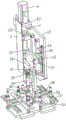
FIG. 1 is a schematic structural view of a curtain wall assembling apparatus for construction engineering according to the present invention;
FIG. 2 is a side view of the present invention;
FIG. 3 is a top view of the present invention;
FIG. 4 is a schematic structural view of the lifting shaft according to the present invention;
FIG. 5 is a schematic view of the structure of the moving plate according to the present invention;
FIG. 6 is a schematic structural view of the cross plate of the present invention;
in the figure: 1. a weighting block; 2. a support pillar; 3. a first nut seat; 4. moving the plate; 5. a protection plate; 6. a first motor; 7. a lifting rotating shaft; 8. a lifting motor; 9. a limiting band; 10. a fixed block; 11. a fixed mount; 12. a lifting motor base; 13. a first slide rail; 14. a sensor; 15. a first lifter plate; 16. a second slide rail; 17. a side plate; 18. a second hydraulic cylinder; 19. a second hydraulic rod; 20. a second lifter plate; 21. mounting a plate; 22. a third slider; 23. a limiting plate; 24. a first screw; 25. a lifting nut seat; 26. a support plate; 27. clamping a plate; 28. a vertical plate; 29. a first hydraulic cylinder; 30. a first hydraulic lever; 31. pulling the block; 32. iron sheets; 33. a first slider; 34. fixing the rod; 35. a suction cup; 36. a base plate; 37. a fixing frame; 38. a transverse plate.
Detailed Description
The technical solutions of the present invention will be described clearly and completely with reference to the following embodiments, and it should be understood that the described embodiments are only a part of the embodiments of the present invention, and not all of the embodiments. All other embodiments, which can be derived by a person skilled in the art from the embodiments given herein without making any creative effort, shall fall within the protection scope of the present invention.
As shown in fig. 1-6, a curtain wall assembling device for building engineering comprises support columns 2, a moving plate 4 and a mounting plate 21, wherein the support columns 2 are respectively arranged at two sides of the bottom of the mounting plate 21, a weight 1 is arranged at the bottom between the two support columns 2, two third slide rails are arranged side by side on the side wall of one side of the mounting plate 21, the moving plate 4 is arranged at one side of the mounting plate 21, two third slide blocks 22 are arranged side by side on the side wall of the moving plate 4 adjacent to the mounting plate 21, the two third slide blocks 22 are respectively arranged on the two third slide rails, a first nut seat 3 is arranged on the moving plate 4 between the two third slide blocks 22, a first screw 24 is arranged between the two third slide rails, a first motor 6 is arranged at one end of the mounting plate 21, the output end of the first motor 6 is in transmission connection with one end of the first screw 24, the first nut seat 3 is arranged on the first screw 24 and is in, a fixed frame 11 is arranged at the top of the moving plate 4 close to one side of the first motor 6, and a limit belt 9 is arranged between the fixed frame 11 and the mounting plate 21;
two ends of the side wall of the moving plate 4 are respectively provided with a side plate 17, one corner of the top of one side plate 17 is fixedly provided with a lifting motor base 12, the top of the lifting motor base 12 is fixedly provided with a lifting motor 8, a lifting rotating shaft 7 is arranged below the lifting motor 8, the top end of the lifting rotating shaft 7 is in transmission connection with the output end of the lifting motor 8, the side plate 17 at one side of the lifting motor base 12 is provided with two first sliding rails 13 side by side, one side of the two first sliding rails 13 is provided with a first lifting plate 15, the side wall of the first lifting plate 15 at one side adjacent to the side plate 17 is provided with two first sliding blocks 33, the two first sliding blocks 33 are respectively arranged on the two first sliding rails 13, the middle position of the side wall of the first lifting plate 15 is provided with a support plate 26, one end of the support plate 26 is provided with a lifting nut base 25, the lifting nut base, the top and the bottom of the supporting plate 26 are provided with limiting plates 23, a first lifting plate 15 on one side of the supporting plate 26 is provided with a clamping plate 27, a side plate 17 of the clamping plate 27 is fixedly provided with a vertical plate 28, a first hydraulic cylinder 29 is arranged below the vertical plate 28, a first hydraulic rod 30 is arranged inside the first hydraulic cylinder 29, the bottom of the first hydraulic rod 30 is provided with a pull block 31, the bottom of the first lifting plate 15 is provided with a bottom plate 36, the bottom of the bottom plate 36 is provided with four fixing frames 37, two ends of the four fixing frames 37 are respectively provided with four fixing rods 34, the bottom of each fixing rod 34 is provided with a suction cup 35, an iron sheet 32 is fixedly arranged on the side wall on one side of the first lifting plate 15, the side plate 17 on one side of the iron sheet 32 is provided with two sensors 14, and the two sensors 14 are respectively;
the other side plate 17 of the movable plate 4 is provided with two second slide rails 16, one side of the side plate 17 is provided with a second lifting plate 20, the second lifting plate 20 adjacent to the side plate 17 is provided with two second slide blocks, the two second slide blocks are respectively arranged on the two second slide rails 16, the middle position of the side plate 17 is fixedly provided with a second hydraulic cylinder 18, the inside of the second hydraulic cylinder 18 is provided with a second hydraulic rod 19, the bottom end of the second hydraulic rod 19 is connected with the second lifting plate 20, the bottom of the second lifting plate 20 is fixedly provided with two transverse plates 38, the two transverse plates 38 are fixedly connected through a support rod, the two transverse plates 38 are provided with six fixing rods 34, the bottom end of each fixing rod 34 is provided with a suction cup 35, when the curtain wall is assembled, the lifting rotating shaft 7 is driven to rotate through the output end of the lifting motor 8, when the lifting rotating shaft 7 rotates, the lifting nut seat 25 is arranged on the lifting rotating shaft 7 and is connected, the first lifting plate 15 moves downwards along the first sliding rail 13, and then the bottom plate 36 moves downwards, so that the suction cup 35 at the bottom of the fixing rod 34 contacts the surface of the curtain wall, when the suction cup 35 is not in contact with the curtain wall, the output end of the first hydraulic cylinder 29 controls the first hydraulic rod 30 inside the suction cup to move, the angle of the bottom plate 36 is adjusted, the suction cup 35 is in contact with the surface of the curtain wall to smoothly suck one end surface of the curtain wall, the suction force of the suction cup 35 on the curtain wall is increased, and the stability is improved; after one end of the curtain wall is sucked and fixed by the suction cup 35 on the bottom plate 36, the second hydraulic cylinder 18 controls the second hydraulic rod 19 in the curtain wall to move downwards, so that the second lifting plate 20 moves downwards along the second slide rail 16, the suction cup 35 at the bottom of the transverse plate 38 is attached to the curtain wall, the suction cup 35 sucks the curtain wall, the other end of the curtain wall is fixed, the integral fixing work of the curtain wall is completed, the lifting motor 8 and the second hydraulic cylinder 18 are respectively controlled to work, the first lifting plate 15 and the second lifting plate 20 move upwards or downwards simultaneously, the height position of the curtain wall is adjusted, the installation work of the curtain walls with different heights is facilitated, a hanging mode is not required for installation, the installation difficulty is reduced, and the installation efficiency is improved; when the installation of the curtain wall in the horizontal direction is needed, the first screw rod 24 is driven to rotate through the output end of the first motor 6, when the first screw rod 24 rotates, because the first nut seat 3 is arranged on the first screw rod 24 and is in threaded connection with the first screw rod 24, the movable plate 4 moves in the horizontal direction along the third slide rail, then the two side plates 17 move, the curtain wall moves in the horizontal direction, the installation of workers is convenient, the position of the support column 2 does not need to be adjusted, and the curtain wall assembling efficiency is improved.
The two ends of the side wall of one side of the mounting plate 21 are respectively and fixedly provided with a bearing seat, the two bearing seats are arranged between the two third sliding rails, the first screw 24 is arranged on the two bearing seats, one end of the first screw 24 penetrates through one of the bearing seats to be connected with the output end of the first motor 6, the first screw 24 is driven to rotate through the output end of the first motor 6, and the first nut seat 3 is arranged on the first screw 24 and is in threaded connection with the first screw 24, so that the movable plate 4 moves on the two third sliding rails, and the purpose of transverse movement of the movable plate 4 is realized.
The top of mount 11 is provided with fixed block 10, and the one end and the fixed block 10 fixed connection of spacing area 9, the fixed top that sets up at mounting panel 21 of the other end of spacing area 9, the outside of lift pivot 7 is provided with guard plate 5 for when movable plate 4 moved on two third slide rails, when movable plate 4 moved the both ends position of third slide rail, mount 11 was withheld to spacing area 9, and the position of spacing movable plate 4 avoids movable plate 4 to drop.
Draw the top of piece 31 and the bottom fixed connection of first hydraulic stem 30, the bottom setting of drawing piece 31 is on bottom plate 36, and the bottom of drawing piece 31 is articulated with bottom plate 36, when meetting sucking disc 35 and curtain contact not level, the first hydraulic stem 30 of its inside output control through first pneumatic cylinder 29 moves, adjust the angle of bottom plate 36, make sucking disc 35 level and smooth with the curtain contact, make sucking disc 35 increase the suction of curtain, stability is improved.
The top of bottom plate 36 is close to middle part position and is provided with two connecting blocks side by side, is provided with the steering spindle between two connecting blocks, and the steering spindle passes the bottom structure of first lifter plate 15, and the steering spindle rotates with first lifter plate 15 to be connected for rotation can take place for bottom plate 36, and the work is adjusted in the control of the first pneumatic cylinder 29 of being convenient for.
Middle part position is provided with the connecting seat on the lateral wall of second lifter plate 20, the bottom fixed connection of connecting seat and second hydraulic stem 19, control its inside second hydraulic stem 19 downstream through second pneumatic cylinder 18, make second lifter plate 20 along second slide rail 16 downstream, make the sucking disc 35 of bottom plate 36 bottom paste on the curtain wall, make sucking disc 35 hold the curtain wall, it is fixed with the both ends of curtain wall, control elevator motor 8 and the work of second pneumatic cylinder 18 respectively, make first lifter plate 15 and second lifter plate 20 upwards or downstream simultaneously, height position to the curtain wall is adjusted, the workman's installation of being convenient for, need not adopt the mode of hanging in midair to install, reduce the installation degree of difficulty, improve the installation effectiveness.
The two transverse plates 38 are parallel to each other, the transverse plates 38 are perpendicular to the second lifting plate 20, the second lifting plate 20 is fixedly connected with the transverse plates 38 at the bottom of the second lifting plate, and after the angle of the curtain wall is adjusted by controlling the first hydraulic cylinder 29, the transverse plates 38 are controlled to move downwards by the second hydraulic cylinder 18, so that the suction cups 35 on the transverse plates 38 can be perpendicularly attached to the surface of the curtain wall, and the curtain wall can be sucked conveniently.
A working method of curtain wall assembling equipment for constructional engineering specifically comprises the following steps:
the method comprises the following steps: when the curtain wall is assembled, the output end of the lifting motor 8 drives the lifting rotating shaft 7 to rotate, when the lifting rotating shaft 7 rotates, the lifting nut seat 25 is arranged on the lifting rotating shaft 7 and is in threaded connection with the lifting rotating shaft 7, so that the first lifting plate 15 moves downwards along the first sliding rail 13, and then the bottom plate 36 moves downwards, the suction cup 35 at the bottom of the fixing rod 34 is in contact with the surface of the curtain wall, when the suction cup 35 is in uneven contact with the curtain wall, the first hydraulic rod 30 in the fixing rod is controlled to move through the output end of the first hydraulic cylinder 29, the angle of the bottom plate 36 is adjusted, and the suction cup 35 is in contact with the surface of the curtain wall to smoothly suck one end surface of the;
step two: after one end of the curtain wall is sucked and fixed by the suction cup 35 on the bottom plate 36, the second hydraulic cylinder 18 controls the second hydraulic rod 19 in the curtain wall to move downwards, so that the second lifting plate 20 moves downwards along the second slide rail 16, the suction cup 35 at the bottom of the transverse plate 38 is attached to the curtain wall, the suction cup 35 sucks the curtain wall, the other end of the curtain wall is fixed, the integral fixing work of the curtain wall is completed, the lifting motor 8 and the second hydraulic cylinder 18 are respectively controlled to work, the first lifting plate 15 and the second lifting plate 20 move upwards or downwards simultaneously, and the height position of the curtain wall is adjusted;
step three: when the installation of the curtain wall in the horizontal direction is needed, the first screw rod 24 is driven to rotate through the output end of the first motor 6, and when the first screw rod 24 rotates, the moving plate 4 moves in the horizontal direction along the third sliding rail due to the fact that the first nut seat 3 is arranged on the first screw rod 24 and is in threaded connection with the first screw rod 24, and then the two side plates 17 move, and the curtain wall moves in the horizontal direction.
The working principle of the invention is as follows: when the curtain wall lifting device is used, the lifting rotating shaft 7 is driven to rotate by the output end of the lifting motor 8 when a curtain wall is assembled, when the lifting rotating shaft 7 rotates, the lifting nut seat 25 is arranged on the lifting rotating shaft 7 and is in threaded connection with the lifting rotating shaft 7, so that the first lifting plate 15 moves downwards along the first slide rail 13, the bottom plate 36 moves downwards, the suction disc 35 at the bottom of the fixed rod 34 is in contact with the surface of the curtain wall, when the suction disc 35 is not in contact with the curtain wall, the first hydraulic rod 30 in the fixed rod is controlled to move by the output end of the first hydraulic cylinder 29, the angle of the bottom plate 36 is adjusted, the suction disc 35 is in contact with the surface of the curtain wall to smoothly suck one end surface of the curtain wall, the suction force of the suction;
after one end of the curtain wall is sucked and fixed by the suction cup 35 on the bottom plate 36, the second hydraulic cylinder 18 controls the second hydraulic rod 19 in the curtain wall to move downwards, so that the second lifting plate 20 moves downwards along the second slide rail 16, the suction cup 35 at the bottom of the transverse plate 38 is attached to the curtain wall, the suction cup 35 sucks the curtain wall, the other end of the curtain wall is fixed, the integral fixing work of the curtain wall is completed, the lifting motor 8 and the second hydraulic cylinder 18 are respectively controlled to work, the first lifting plate 15 and the second lifting plate 20 move upwards or downwards simultaneously, the height position of the curtain wall is adjusted, the installation work of the curtain walls with different heights is facilitated, a hanging mode is not required for installation, the installation difficulty is reduced, and the installation efficiency is improved;
when the installation of the curtain wall in the horizontal direction is needed, the first screw rod 24 is driven to rotate through the output end of the first motor 6, when the first screw rod 24 rotates, because the first nut seat 3 is arranged on the first screw rod 24 and is in threaded connection with the first screw rod 24, the movable plate 4 moves in the horizontal direction along the third slide rail, then the two side plates 17 move, the curtain wall moves in the horizontal direction, the installation of workers is convenient, the position of the support column 2 does not need to be adjusted, and the curtain wall assembling efficiency is improved.
The preferred embodiments of the invention disclosed above are intended to be illustrative only. The preferred embodiments are not intended to be exhaustive or to limit the invention to the precise embodiments disclosed. Obviously, many modifications and variations are possible in light of the above teaching. The embodiments were chosen and described in order to best explain the principles of the invention and the practical application, to thereby enable others skilled in the art to best utilize the invention. The invention is limited only by the claims and their full scope and equivalents.
Claims (8)
1. The curtain wall assembling equipment for the building engineering is characterized by comprising support columns (2), a movable plate (4) and a mounting plate (21), wherein the support columns (2) are respectively arranged on two sides of the bottom of the mounting plate (21), a weighting block (1) is arranged at the bottom between the two support columns (2), two third slide rails are arranged on the side wall of one side of the mounting plate (21) side by side, the movable plate (4) is arranged on one side of the mounting plate (21), two third slide blocks (22) are arranged on the side wall of the movable plate (4) on the side adjacent to the mounting plate (21) side by side, the two third slide blocks (22) are respectively arranged on the two third slide rails, a first nut seat (3) is arranged on the movable plate (4) between the two third slide blocks (22), a first screw rod (24) is arranged between the two third slide rails, and a first motor (6) is arranged at one, the output end of the first motor (6) is in transmission connection with one end of a first screw rod (24), a first nut seat (3) is arranged on the first screw rod (24) and is in threaded connection with the first screw rod (24), a fixed frame (11) is arranged at the top of the moving plate (4) close to one side of the first motor (6), and a limiting belt (9) is arranged between the fixed frame (11) and the mounting plate (21);
the two ends of the side wall of the movable plate (4) are respectively provided with a side plate (17), one corner of the top of one side plate (17) is fixedly provided with a lifting motor base (12), the top of the lifting motor base (12) is fixedly provided with a lifting motor (8), a lifting rotating shaft (7) is arranged below the lifting motor (8), the top end of the lifting rotating shaft (7) is in transmission connection with the output end of the lifting motor (8), the side plate (17) at one side of the lifting motor base (12) is provided with two first sliding rails (13) side by side, one side of the two first sliding rails (13) is provided with a first lifting plate (15), the side wall of the first lifting plate (15) at one side adjacent to the side plate (17) is provided with two first sliding blocks (33), the two first sliding blocks (33) are respectively arranged on the two first sliding rails (13), and a supporting plate (26) is arranged in the middle of the side, one end of a supporting plate (26) is provided with a lifting nut seat (25), the lifting nut seat (25) is arranged on a lifting rotating shaft (7) and is connected with the lifting rotating shaft (7) through threads, limiting plates (23) are arranged at the top and the bottom of the supporting plate (26), a clamping plate (27) is arranged on a first lifting plate (15) on one side of the supporting plate (26), a vertical plate (28) is fixedly arranged on a side plate (17) of the clamping plate (27), a first hydraulic cylinder (29) is arranged below the vertical plate (28), a first hydraulic rod (30) is arranged inside the first hydraulic cylinder (29), a pull block (31) is arranged at the bottom of the first hydraulic rod (30), a bottom plate (36) is arranged at the bottom of the first lifting plate (15), four fixing frames (37) are arranged at the bottom of the bottom plate (36), and four fixing rods (34) are respectively arranged at two ends of the four fixing, a sucker (35) is arranged at the bottom of each fixing rod (34), an iron sheet (32) is fixedly arranged on the side wall of one side of the first lifting plate (15), two sensors (14) are arranged on the side plate (17) of one side of the iron sheet (32), and the two sensors (14) are respectively arranged at the top and the bottom of the side wall of the side plate (17);
two second sliding rails (16) are arranged on the other side plate (17) on the moving plate (4), a second lifting plate (20) is arranged on one side of the side plate (17), two second sliders are arranged on a second lifting plate (20) on one side adjacent to the side plate (17), the two second sliders are arranged on two second sliding rails (16) respectively, a second hydraulic cylinder (18) is fixedly arranged at the middle position of the side plate (17), a second hydraulic rod (19) is arranged inside the second hydraulic cylinder (18), the bottom end of the second hydraulic rod (19) is connected with the second lifting plate (20), two transverse plates (38) are fixedly arranged at the bottom of the second lifting plate (20), the two transverse plates (38) are fixedly connected through supporting rods, six fixing rods (34) are arranged on the two transverse plates (38), and a sucking disc (35) is arranged at the bottom end of each fixing rod (34).
2. The curtain wall assembling equipment for the building engineering as claimed in claim 1, wherein bearing seats are respectively fixedly arranged at two ends of a side wall of one side of the mounting plate (21), the two bearing seats are arranged between the two third sliding rails, the first screw (24) is arranged on the two bearing seats, and one end of the first screw (24) penetrates through one of the bearing seats to be connected with the output end of the first motor (6).
3. The curtain wall assembling equipment for the building engineering as claimed in claim 1, wherein a fixing block (10) is arranged at the top of the fixing frame (11), one end of the limiting belt (9) is fixedly connected with the fixing block (10), the other end of the limiting belt (9) is fixedly arranged at the top of the mounting plate (21), and a protection plate (5) is arranged outside the lifting rotating shaft (7).
4. The curtain wall assembling equipment for building engineering according to claim 1, wherein the top end of the pulling block (31) is fixedly connected with the bottom end of the first hydraulic rod (30), the bottom end of the pulling block (31) is arranged on the bottom plate (36), and the bottom end of the pulling block (31) is hinged with the bottom plate (36).
5. The curtain wall assembling device for building engineering according to claim 1, wherein two connecting blocks are arranged on the top of the bottom plate (36) near the middle side by side, a steering shaft is arranged between the two connecting blocks, the steering shaft passes through the bottom structure of the first lifting plate (15), and the steering shaft is rotatably connected with the first lifting plate (15).
6. The curtain wall assembling equipment for building engineering according to claim 1, wherein a connecting seat is arranged at the middle position on the side wall of the second lifting plate (20), and the connecting seat is fixedly connected with the bottom end of the second hydraulic rod (19).
7. The curtain wall assembling equipment for building engineering as claimed in claim 1, wherein the two transverse plates (38) are parallel to each other, the transverse plates (38) are perpendicular to the second lifting plate (20), and the second lifting plate (20) is fixedly connected with the transverse plates (38) at the bottom of the second lifting plate.
8. An operating method of a curtain wall assembling apparatus for construction engineering according to any one of claims 1 to 7, characterized in that the operating method comprises the following steps:
the method comprises the following steps: when the curtain wall is assembled, the lifting rotating shaft (7) is driven to rotate through the output end of the lifting motor (8), when the lifting rotating shaft (7) rotates, the lifting nut seat (25) is arranged on the lifting rotating shaft (7) and is in threaded connection with the lifting rotating shaft (7), so that the first lifting plate (15) moves downwards along the first sliding rail (13), the bottom plate (36) moves downwards, the sucker (35) at the bottom of the fixing rod (34) contacts with the surface of the curtain wall, when the sucker (35) is not in contact with the curtain wall, the first hydraulic rod (30) in the fixing rod is controlled to move through the output end of the first hydraulic cylinder (29), the angle of the bottom plate (36) is adjusted, and the sucker (35) is in contact with the surface of the curtain wall to suck one end surface of the curtain wall flatly;
step two: after one end of the curtain wall is sucked and fixed by a sucking disc (35) on a bottom plate (36), a second hydraulic cylinder (18) is used for controlling a second hydraulic rod (19) in the curtain wall to move downwards, so that a second lifting plate (20) moves downwards along a second sliding rail (16), the sucking disc (35) at the bottom of a transverse plate (38) is attached to the curtain wall, the sucking disc (35) sucks the curtain wall, the other end of the curtain wall is fixed, the whole fixing work of the curtain wall is completed, a lifting motor (8) and the second hydraulic cylinder (18) are respectively controlled to work, so that a first lifting plate (15) and a second lifting plate (20) simultaneously move upwards or downwards, and the height position of the curtain wall is adjusted;
step three: when the installation of the curtain wall in the horizontal direction is needed, the first screw rod (24) is driven to rotate through the output end of the first motor (6), and when the first screw rod (24) rotates, the movable plate (4) moves in the horizontal direction along the third sliding rail due to the fact that the first nut seat (3) is arranged on the first screw rod (24) and is in threaded connection with the first screw rod (24), and then the two side plates (17) move to enable the curtain wall to move in the horizontal direction.
Priority Applications (1)
| Application Number | Priority Date | Filing Date | Title |
|---|---|---|---|
| CN201910765667.3A CN110409847B (en) | 2019-08-19 | 2019-08-19 | Curtain wall assembling equipment for constructional engineering and working method thereof |
Applications Claiming Priority (1)
| Application Number | Priority Date | Filing Date | Title |
|---|---|---|---|
| CN201910765667.3A CN110409847B (en) | 2019-08-19 | 2019-08-19 | Curtain wall assembling equipment for constructional engineering and working method thereof |
Publications (2)
| Publication Number | Publication Date |
|---|---|
| CN110409847A CN110409847A (en) | 2019-11-05 |
| CN110409847B true CN110409847B (en) | 2021-04-13 |
Family
ID=68368020
Family Applications (1)
| Application Number | Title | Priority Date | Filing Date |
|---|---|---|---|
| CN201910765667.3A Active CN110409847B (en) | 2019-08-19 | 2019-08-19 | Curtain wall assembling equipment for constructional engineering and working method thereof |
Country Status (1)
| Country | Link |
|---|---|
| CN (1) | CN110409847B (en) |
Families Citing this family (1)
| Publication number | Priority date | Publication date | Assignee | Title |
|---|---|---|---|---|
| CN111255103B (en) * | 2020-03-10 | 2020-12-08 | 山东鑫光节能科技有限公司 | Construction process for heat preservation treatment of energy-saving building wall |
Citations (7)
| Publication number | Priority date | Publication date | Assignee | Title |
|---|---|---|---|---|
| JPH08259193A (en) * | 1995-03-27 | 1996-10-08 | Toshiba Corp | Cassette carrier device |
| CN204569343U (en) * | 2014-12-05 | 2015-08-19 | 深圳市创思泰科技有限公司 | Before and after Pneumatic vacuum, low-angle upset adds 360 degree of turnover sucker machines and application apparatus thereof |
| CN205908030U (en) * | 2016-08-03 | 2017-01-25 | 浙江南方装饰工程有限公司 | Curtain wall construction device |
| CN107585711A (en) * | 2017-10-17 | 2018-01-16 | 广东亚克迪智能物流科技有限公司 | A kind of forklift for moving glass |
| CN207845020U (en) * | 2017-07-13 | 2018-09-11 | 浙江永联建设工程股份有限公司 | It is easily installed the hanger of glass |
| CN109208920A (en) * | 2018-11-15 | 2019-01-15 | 河北工业大学 | A kind of heavy construction curtain wall mounting robot |
| CN109779267A (en) * | 2019-02-25 | 2019-05-21 | 天津中科先进技术研究院有限公司 | Automatic curtain wall assembling equipment and using method |
-
2019
- 2019-08-19 CN CN201910765667.3A patent/CN110409847B/en active Active
Patent Citations (7)
| Publication number | Priority date | Publication date | Assignee | Title |
|---|---|---|---|---|
| JPH08259193A (en) * | 1995-03-27 | 1996-10-08 | Toshiba Corp | Cassette carrier device |
| CN204569343U (en) * | 2014-12-05 | 2015-08-19 | 深圳市创思泰科技有限公司 | Before and after Pneumatic vacuum, low-angle upset adds 360 degree of turnover sucker machines and application apparatus thereof |
| CN205908030U (en) * | 2016-08-03 | 2017-01-25 | 浙江南方装饰工程有限公司 | Curtain wall construction device |
| CN207845020U (en) * | 2017-07-13 | 2018-09-11 | 浙江永联建设工程股份有限公司 | It is easily installed the hanger of glass |
| CN107585711A (en) * | 2017-10-17 | 2018-01-16 | 广东亚克迪智能物流科技有限公司 | A kind of forklift for moving glass |
| CN109208920A (en) * | 2018-11-15 | 2019-01-15 | 河北工业大学 | A kind of heavy construction curtain wall mounting robot |
| CN109779267A (en) * | 2019-02-25 | 2019-05-21 | 天津中科先进技术研究院有限公司 | Automatic curtain wall assembling equipment and using method |
Also Published As
| Publication number | Publication date |
|---|---|
| CN110409847A (en) | 2019-11-05 |
Similar Documents
| Publication | Publication Date | Title |
|---|---|---|
| CN112376920B (en) | Splicing, installing and constructing method for large-span steel structure building roof | |
| CN111704046A (en) | Unit type glass curtain wall lifting device and construction method | |
| CN110615279A (en) | Feeding device for ceramic tile production and using method thereof | |
| CN110409847B (en) | Curtain wall assembling equipment for constructional engineering and working method thereof | |
| CN108750902A (en) | A kind of glass adjustment frame | |
| CN212836778U (en) | Manipulator is used in supplementary installation of high altitude curtain | |
| CN110778126B (en) | Construction method of building glass curtain wall | |
| CN211369175U (en) | Curtain wall mounting device | |
| WO2023184882A1 (en) | Material lifting device | |
| CN216235816U (en) | Glass curtain wall installation device | |
| CN217555725U (en) | Eccentric elevating platform for ground push plate conveying system | |
| JP2547892B2 (en) | Panel holding device | |
| CN213015264U (en) | Tool device is pasted on elevator car marble floor | |
| CN111137059B (en) | Automatic mounting equipment for indoor decorative picture | |
| CN112031435A (en) | Auxiliary installation device and method for glass curtain wall | |
| CN206969065U (en) | A kind of aluminium laminator sheet material carrying mechanism | |
| CN220602519U (en) | Building engineering straightness detection mechanism that hangs down | |
| CN213537051U (en) | Gantry crane with electric hoist | |
| CN220596815U (en) | Assembled building materials hoisting device | |
| CN215670358U (en) | Super large glass rib lines curtain | |
| CN220866882U (en) | Unit curtain wall hoisting trolley | |
| CN219117527U (en) | Pallet hot galvanizing hanger device | |
| CN113494178A (en) | Self-stabilizing hanging basket based on mechanical vision system | |
| CN219031575U (en) | Building support hoisting device for membrane building construction | |
| CN219952635U (en) | Lifting hanging basket for building construction |
Legal Events
| Date | Code | Title | Description |
|---|---|---|---|
| PB01 | Publication | ||
| PB01 | Publication | ||
| SE01 | Entry into force of request for substantive examination | ||
| SE01 | Entry into force of request for substantive examination | ||
| GR01 | Patent grant | ||
| GR01 | Patent grant |