CN110394754B - Adjustable wrench - Google Patents
Adjustable wrench Download PDFInfo
- Publication number
- CN110394754B CN110394754B CN201910672732.8A CN201910672732A CN110394754B CN 110394754 B CN110394754 B CN 110394754B CN 201910672732 A CN201910672732 A CN 201910672732A CN 110394754 B CN110394754 B CN 110394754B
- Authority
- CN
- China
- Prior art keywords
- shell
- bolt
- grip block
- rotary table
- handle
- Prior art date
- Legal status (The legal status is an assumption and is not a legal conclusion. Google has not performed a legal analysis and makes no representation as to the accuracy of the status listed.)
- Active
Links
Images


Classifications
-
- B—PERFORMING OPERATIONS; TRANSPORTING
- B25—HAND TOOLS; PORTABLE POWER-DRIVEN TOOLS; MANIPULATORS
- B25B—TOOLS OR BENCH DEVICES NOT OTHERWISE PROVIDED FOR, FOR FASTENING, CONNECTING, DISENGAGING OR HOLDING
- B25B13/00—Spanners; Wrenches
- B25B13/10—Spanners; Wrenches with adjustable jaws
- B25B13/12—Spanners; Wrenches with adjustable jaws the jaws being slidable
- B25B13/16—Spanners; Wrenches with adjustable jaws the jaws being slidable by screw or nut
Abstract
The invention discloses an adjustable wrench, which comprises a handle, a shell, a rotary table and clamping blocks, wherein an adjusting bolt is arranged on the handle, the rotary table is arranged in the shell, teeth on the rotary table are meshed with the adjusting bolt, and six clamping blocks are further arranged in the shell. The adjusting screw rod drives the turntable to rotate, the turntable drives the six clamping blocks to move on the set track, and a screwed nut or bolt is clamped by a regular hexagon formed by the six clamping blocks, so that the phenomenon of slipping is avoided, and the corners of the nut or the bolt are not damaged; the scales are arranged, the caliber size can be accurately determined, the one-step adjustment is realized, and the working efficiency is improved.
Description
Technical Field
The invention belongs to the technical field of hardware tools, and particularly relates to an adjustable wrench.
Background
The wrench is a tool for installing and disassembling the nut or the bolt, the wrench comprises a handle and a wrench head fixedly connected with one end of the handle, the wrench handle is held by a user, and the wrench head is used for clamping the nut or the bolt. Common wrenches comprise a dead wrench and an adjustable wrench, the dead wrench is only suitable for nuts or bolts with certain specifications, a plurality of dead wrenches with different calibers need to be arranged during working, and the carrying and the use are inconvenient; the adjustable spanner can adjust the size of the caliber of the spanner head through the adjusting bolt, can be suitable for nuts or bolts with different specifications, and has the following problems: the jaw of the wrench head is semi-surrounded, and when the wrench is used, the acting force of the wrench is concentrated on a half corner of the nut or the bolt, so that the corner of the nut or the bolt is unevenly stressed, the phenomenon of slipping is easy to occur, and the corner of the nut or the bolt is damaged; in addition, the size value of the jaw cannot be determined, the jaw needs to be tried out and adjusted repeatedly, and the working efficiency is low.
Disclosure of Invention
In order to solve the defects of the prior art, the invention provides an adjustable wrench.
The technical scheme adopted by the invention is as follows: the utility model provides an adjustable spanner, includes handle, casing, carousel, grip block, characterized by:
the handle is cylindrical, a hole groove is formed in one end of the handle, an adjusting bolt is arranged in the hole groove, and a spiral groove is formed in the adjusting bolt;
the shell is fixedly arranged at one end, close to the adjusting bolt, of the handle, the shell is in an annular hollow cylindrical shape, the shell comprises a bottom shell and a shell cover, the bottom shell and the handle are integrally formed, the shell cover is fixed on the bottom shell through screws, six first guide grooves are uniformly formed in the position, close to the side edge of the outer periphery, of the shell cover, the first guide grooves are in an inclined shape, six first guide bolts are uniformly formed in the position, close to the side edge of the inner periphery, of the shell cover, and the first guide bolts face towards the bottom;
the rotary table is used for transmitting the rotation of the adjusting bolt to the clamping block and guiding the movement of the clamping block, the rotary table is arranged in the bottom shell and can rotate around the center of the bottom shell, teeth are arranged on the outer peripheral side edge of the rotary table, the teeth on the rotary table are meshed with the spiral grooves in the adjusting bolt, the rotary adjusting bolt can drive the rotary table to rotate, six second guide grooves are uniformly arranged on the rotary table close to the outer peripheral side edge, and the second guide grooves are radial;
the grip block is used for the centre gripping by screwed nut or bolt, the grip block is six and the shape is identical, the grip block is the arrow point shape, the grip block is most advanced to be 60, the grip block tail end is equipped with the second uide bolt, the second uide bolt both ends are respectively towards the upper and lower side of grip block, the grip block middle part is equipped with the third guide way, the third guide way is the axial and slightly inclines, six grip blocks evenly set up between carousel and cap, six grip block most advanced towards the casing center, insert the first guide way of cap and the second guide way of carousel respectively in the second uide bolt both ends on the grip block, the third guide way of grip block is inserted to the first uide bolt on the cap.
Furthermore, the rotating angle of the rotating disc determines the size of the caliber enclosed by the six clamping blocks, scales are arranged on the rotating disc, a perspective hole is arranged on the shell, and the scale value displayed by the perspective hole represents the size of the caliber enclosed by the six clamping blocks.
Furthermore, a hanging hole is formed in one end, far away from the shell, of the handle.
The working process of the invention is as follows: and rotating the adjusting screw, driving the turntable to rotate by the adjusting screw, driving the six clamping blocks to move on the set track by the turntable, changing the caliber of a regular hexagon surrounded by the six clamping blocks, and determining the rotating amplitude of the adjusting screw according to the size of a screwed nut or bolt and the scale value displayed by the perspective hole.
The invention has the beneficial effects that: the regular hexagonal hole formed by the six clamping blocks is right used for clamping six corners of the nut or the bolt, the acting force of the wrench is uniformly distributed on the six corners of the nut or the bolt, the phenomenon of slipping is avoided, and the corners of the nut or the bolt are not damaged; the scales are arranged, the caliber size can be accurately determined, the one-step adjustment is realized, and the working efficiency is improved.
Drawings
Fig. 1 is a schematic diagram of the appearance structure of the present invention.
Fig. 2 is a schematic diagram of an exploded structure of the present invention.
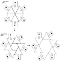
FIG. 3 is a schematic view of the structure of the housing cover of the present invention.
Fig. 4 is a schematic view of the turntable structure of the present invention.
Fig. 5 is a schematic view of the structure of the clamping member of the present invention.
Fig. 6 is a schematic view of a clamping member of the invention in a changed structure.
Detailed Description
The invention is further described below with reference to the accompanying drawings.
The utility model provides an adjustable spanner, includes handle 1, casing 2, carousel 10, grip block 5, characterized by:
the handle 1 is cylindrical, a hole groove is formed in one end of the handle 1, an adjusting bolt 3 is arranged in the hole groove, and a spiral groove is formed in the adjusting bolt 3;
the shell 2 is fixedly arranged at one end, close to the adjusting bolt 3, of the handle 1, the shell 2 is in an annular hollow cylindrical shape, the shell comprises a bottom shell 7 and a shell cover 8, the bottom shell 7 and the handle 1 are integrally formed, the shell cover 8 is fixed on the bottom shell 7 through screws, six first guide grooves 4 are uniformly formed in the position, close to the outer peripheral side edge, of the shell cover 8, the first guide grooves 4 are in an inclined shape, six first guide bolts 9 are uniformly formed in the position, close to the inner peripheral side edge, of the shell cover 8, and the first guide bolts 9 face the bottom shell 7;
the rotary table 10 is used for transmitting the rotation of the adjusting bolt 3 to the clamping block 5 and guiding the movement of the clamping block 5, the rotary table 10 is arranged in the bottom case 7 and can rotate around the center of the bottom case 7, teeth 11 are arranged on the periphery side edge of the rotary table 10, the teeth 11 on the rotary table are meshed with spiral grooves on the adjusting bolt 3, the rotary table 10 can be driven to rotate by rotating the adjusting bolt 3, six second guide grooves 12 are uniformly arranged on the rotary table 10 close to the periphery side edge, and the second guide grooves 12 are radial;
the clamping block 5 is used for clamping screwed nuts or bolts, the clamping block 5 is six and has the same shape, the clamping block 5 is in an arrow shape, the pointed end 16 of the clamping block 5 is 60 degrees, the tail end of the clamping block 5 is provided with a second guide bolt 14, the two ends of the second guide bolt 14 face the upper side face and the lower side face of the clamping block respectively, the middle of the clamping block 5 is provided with a third guide groove 15, the third guide groove 15 is slightly inclined in the axial direction, the six clamping blocks 5 are uniformly arranged between the rotary table 10 and the shell cover 8, the pointed ends of the six clamping blocks 5 face the center of the shell 2, the two ends of the second guide bolt 14 on the clamping block 5 are respectively inserted into the first guide groove 4 of the shell cover and the second guide groove 12 of the rotary table, and the first guide bolt 9 on the shell cover 8 is inserted into the.
Further, the rotation angle of the rotary table 10 determines the size of the caliber enclosed by the six clamping blocks 5, the rotary table 10 is provided with scales (not shown in the figure), the shell 2 is provided with a perspective hole (not shown in the figure), and the scale value displayed by the perspective hole represents the size of the caliber enclosed by the six clamping blocks 5.
Further, a hanging hole 6 is formed in one end, far away from the shell 2, of the handle 1.
The working process of the invention is as follows: the adjusting screw rod 3 is rotated, the adjusting screw rod 3 drives the rotary table 10 to rotate, the rotary table 10 drives the six clamping blocks 5 to move on a set track, the caliber of a regular hexagon formed by the six clamping blocks 5 changes, and the rotating amplitude of the adjusting screw rod is determined according to the size of a screwed nut or bolt and the scale value displayed by the perspective hole.
Claims (3)
1. The utility model provides an adjustable spanner, includes handle, casing, carousel, grip block, characterized by:
the handle is cylindrical, a hole groove is formed in one end of the handle, an adjusting bolt is arranged in the hole groove, and a spiral groove is formed in the adjusting bolt;
the shell is fixedly arranged at one end, close to the adjusting bolt, of the handle, the shell is in an annular hollow cylindrical shape, the shell comprises a bottom shell and a shell cover, the bottom shell and the handle are integrally formed, the shell cover is fixed on the bottom shell through screws, six first guide grooves are uniformly formed in the position, close to the side edge of the outer periphery, of the shell cover, the first guide grooves are in an inclined shape, six first guide bolts are uniformly formed in the position, close to the side edge of the inner periphery, of the shell cover, and the first guide bolts face towards the bottom;
the rotary table is used for transmitting the rotation of the adjusting bolt to the clamping block and guiding the movement of the clamping block, the rotary table is arranged in the bottom shell and can rotate around the center of the bottom shell, teeth are arranged on the outer peripheral side edge of the rotary table, the teeth on the rotary table are meshed with the spiral grooves in the adjusting bolt, the rotary adjusting bolt can drive the rotary table to rotate, six second guide grooves are uniformly arranged on the rotary table close to the outer peripheral side edge, and the second guide grooves are radial;
the grip block is used for the centre gripping by screwed nut or bolt, the grip block is six and the shape is identical, the grip block is the arrow point shape, the grip block is most advanced to be 60, the grip block tail end is equipped with the second uide bolt, the second uide bolt both ends are respectively towards the upper and lower side of grip block, the grip block middle part is equipped with the third guide way, the third guide way is the axial and slightly inclines, six grip blocks evenly set up between carousel and cap, six grip block most advanced towards the casing center, insert the first guide way of cap and the second guide way of carousel respectively in the second uide bolt both ends on the grip block, the third guide way of grip block is inserted to the first uide bolt on the cap.
2. The adjustable wrench as claimed in claim 1, wherein: the rotary disc is provided with scales, and the shell is provided with a perspective hole.
3. The adjustable wrench as claimed in claim 1, wherein: and one end of the handle, which is far away from the shell, is provided with a hanging hole.
Priority Applications (1)
| Application Number | Priority Date | Filing Date | Title |
|---|---|---|---|
| CN201910672732.8A CN110394754B (en) | 2019-07-24 | 2019-07-24 | Adjustable wrench |
Applications Claiming Priority (1)
| Application Number | Priority Date | Filing Date | Title |
|---|---|---|---|
| CN201910672732.8A CN110394754B (en) | 2019-07-24 | 2019-07-24 | Adjustable wrench |
Publications (2)
| Publication Number | Publication Date |
|---|---|
| CN110394754A CN110394754A (en) | 2019-11-01 |
| CN110394754B true CN110394754B (en) | 2021-04-13 |
Family
ID=68324888
Family Applications (1)
| Application Number | Title | Priority Date | Filing Date |
|---|---|---|---|
| CN201910672732.8A Active CN110394754B (en) | 2019-07-24 | 2019-07-24 | Adjustable wrench |
Country Status (1)
| Country | Link |
|---|---|
| CN (1) | CN110394754B (en) |
Citations (5)
| Publication number | Priority date | Publication date | Assignee | Title |
|---|---|---|---|---|
| DE857178C (en) * | 1951-01-21 | 1952-11-27 | Georg Diebel | Ring-shaped wrench with opposing radially adjustable jaws |
| GB9513003D0 (en) * | 1992-12-24 | 1995-10-11 | Hartley Bernard M | Adjustable aperture apparatus |
| CN106272189A (en) * | 2016-10-20 | 2017-01-04 | 钦州学院 | A kind of spanner being adapted to different nut diameter |
| CN106346399A (en) * | 2016-11-11 | 2017-01-25 | 苏州创必成电子科技有限公司 | Novel adjustable spanner convenient in aperture adjustment |
| CN107932384A (en) * | 2017-11-24 | 2018-04-20 | 深圳技术大学(筹) | The spanner of adjustable bore |
Family Cites Families (7)
| Publication number | Priority date | Publication date | Assignee | Title |
|---|---|---|---|---|
| US877773A (en) * | 1907-04-24 | 1908-01-28 | Jens Cr Holm | Wrench. |
| CN203317281U (en) * | 2013-06-05 | 2013-12-04 | 中国石油天然气股份有限公司 | Worm and gear wrench for mounting and demounting bolts in small spaces |
| CN203680163U (en) * | 2013-12-26 | 2014-07-02 | 绍兴恒力工具有限公司 | Adjustable ratchet wrench |
| ITUB20154075A1 (en) * | 2015-10-06 | 2017-04-06 | Pelleossa Srl | AN ADJUSTABLE KEY TO GRAB AND TURN DICE, BOLTS AND OTHER HEXAGONAL SECTION PROFILES |
| CN106378739B (en) * | 2016-11-11 | 2018-07-10 | 江苏科力斯通新材料有限公司 | The Novel electric wrench adjusted convenient for bore |
| CN106392964B (en) * | 2016-11-11 | 2018-05-08 | 盐城市新澳精密锻造有限公司 | Bore adjustable spanner |
| CN207495369U (en) * | 2017-11-23 | 2018-06-15 | 攀钢集团西昌钢钒有限公司 | A kind of adjustable spanner |
-
2019
- 2019-07-24 CN CN201910672732.8A patent/CN110394754B/en active Active
Patent Citations (5)
| Publication number | Priority date | Publication date | Assignee | Title |
|---|---|---|---|---|
| DE857178C (en) * | 1951-01-21 | 1952-11-27 | Georg Diebel | Ring-shaped wrench with opposing radially adjustable jaws |
| GB9513003D0 (en) * | 1992-12-24 | 1995-10-11 | Hartley Bernard M | Adjustable aperture apparatus |
| CN106272189A (en) * | 2016-10-20 | 2017-01-04 | 钦州学院 | A kind of spanner being adapted to different nut diameter |
| CN106346399A (en) * | 2016-11-11 | 2017-01-25 | 苏州创必成电子科技有限公司 | Novel adjustable spanner convenient in aperture adjustment |
| CN107932384A (en) * | 2017-11-24 | 2018-04-20 | 深圳技术大学(筹) | The spanner of adjustable bore |
Also Published As
| Publication number | Publication date |
|---|---|
| CN110394754A (en) | 2019-11-01 |
Similar Documents
| Publication | Publication Date | Title |
|---|---|---|
| CN2178162Y (en) | Portable construction tool collector | |
| CN204546041U (en) | The horizontal bench vice of machine of adjustable holding workpiece | |
| CN210587209U (en) | Driving center for turning heavy half shaft | |
| CN110394754B (en) | Adjustable wrench | |
| CN103182652A (en) | Clamping method and device for cutting junction surface of semi-open thin-wall container | |
| CN111843896B (en) | Adjustable inner hexagonal socket wrench | |
| CN210414326U (en) | Internal hexagonal wrench | |
| CN201329562Y (en) | Adjustable spanner | |
| CN110270953A (en) | A kind of bore adjustable spanner | |
| CN206732880U (en) | Adjustable wrench | |
| CN106392961B (en) | The monkey wrench adjusted easy to bore | |
| CN2409012Y (en) | Clamped socket wrench | |
| CN213615337U (en) | Clamping tool suitable for milling hexagonal nut | |
| CN111958512B (en) | Clamping tool structure for flywheel machining | |
| CN114211061A (en) | Length-adjustable circular die tool | |
| CN209110937U (en) | A kind of novel monkey wrench | |
| CN207104756U (en) | Monkey wrench | |
| CN111673662A (en) | Wind big gun interface formula all-round spanner | |
| CN215589060U (en) | Nut dismounting device convenient to operation | |
| CN218801911U (en) | Hardware screwdriver | |
| CN216781658U (en) | Novel piston dismouting adjustable spanner | |
| CN201960501U (en) | Multi-head spanner | |
| CN211362035U (en) | Adjustable wrench capable of being adjusted freely | |
| CN212824875U (en) | Flat tongs | |
| CN218504382U (en) | Double offset ring spanner convenient to adjust |
Legal Events
| Date | Code | Title | Description |
|---|---|---|---|
| PB01 | Publication | ||
| PB01 | Publication | ||
| SE01 | Entry into force of request for substantive examination | ||
| SE01 | Entry into force of request for substantive examination | ||
| TA01 | Transfer of patent application right |
Effective date of registration: 20210324 Address after: 422000 Lishan village, jiulongling Town, Shaodong county, Shaoyang City, Hunan Province Applicant after: Shaodong Guangzhong Hardware Technology Development Co.,Ltd. Address before: 476000 Shangqiu No.9 middle school, Beihai Road, Suiyang District, Shangqiu City, Henan Province Applicant before: Wei Changtong |
|
| TA01 | Transfer of patent application right | ||
| GR01 | Patent grant | ||
| GR01 | Patent grant |