CN110314070B - Passive rehabilitation device for paralytic patient - Google Patents
Passive rehabilitation device for paralytic patient Download PDFInfo
- Publication number
- CN110314070B CN110314070B CN201910724657.5A CN201910724657A CN110314070B CN 110314070 B CN110314070 B CN 110314070B CN 201910724657 A CN201910724657 A CN 201910724657A CN 110314070 B CN110314070 B CN 110314070B
- Authority
- CN
- China
- Prior art keywords
- rod
- plate
- hinged
- cylinder
- connecting rod
- Prior art date
- Legal status (The legal status is an assumption and is not a legal conclusion. Google has not performed a legal analysis and makes no representation as to the accuracy of the status listed.)
- Expired - Fee Related
Links
- 230000001769 paralizing effect Effects 0.000 title description 2
- 206010033799 Paralysis Diseases 0.000 claims abstract description 15
- 230000002457 bidirectional effect Effects 0.000 claims description 10
- 230000003014 reinforcing effect Effects 0.000 claims description 7
- 230000007246 mechanism Effects 0.000 claims description 5
- 230000000712 assembly Effects 0.000 claims description 4
- 238000000429 assembly Methods 0.000 claims description 4
- 230000005540 biological transmission Effects 0.000 claims description 3
- 239000003638 chemical reducing agent Substances 0.000 claims description 3
- 230000033001 locomotion Effects 0.000 abstract description 12
- 230000009286 beneficial effect Effects 0.000 abstract description 2
- 230000009471 action Effects 0.000 description 4
- 230000000694 effects Effects 0.000 description 4
- 230000017531 blood circulation Effects 0.000 description 3
- 208000037265 diseases, disorders, signs and symptoms Diseases 0.000 description 3
- 230000006870 function Effects 0.000 description 3
- 210000003141 lower extremity Anatomy 0.000 description 3
- 210000000056 organ Anatomy 0.000 description 3
- 238000010586 diagram Methods 0.000 description 2
- 201000010099 disease Diseases 0.000 description 2
- 210000003414 extremity Anatomy 0.000 description 2
- 230000005484 gravity Effects 0.000 description 2
- 230000010355 oscillation Effects 0.000 description 2
- 238000002560 therapeutic procedure Methods 0.000 description 2
- 208000035240 Disease Resistance Diseases 0.000 description 1
- 208000012661 Dyskinesia Diseases 0.000 description 1
- 238000007792 addition Methods 0.000 description 1
- 230000007774 longterm Effects 0.000 description 1
- 230000004060 metabolic process Effects 0.000 description 1
- 238000000034 method Methods 0.000 description 1
- 238000012986 modification Methods 0.000 description 1
- 230000004048 modification Effects 0.000 description 1
- 230000007659 motor function Effects 0.000 description 1
- 210000003205 muscle Anatomy 0.000 description 1
- 210000005036 nerve Anatomy 0.000 description 1
- 210000000653 nervous system Anatomy 0.000 description 1
- 210000000715 neuromuscular junction Anatomy 0.000 description 1
- 230000000474 nursing effect Effects 0.000 description 1
- 230000035778 pathophysiological process Effects 0.000 description 1
- 230000008092 positive effect Effects 0.000 description 1
- 208000037920 primary disease Diseases 0.000 description 1
- 230000008569 process Effects 0.000 description 1
- 238000011084 recovery Methods 0.000 description 1
- 238000006467 substitution reaction Methods 0.000 description 1
- 208000024891 symptom Diseases 0.000 description 1
- 210000001519 tissue Anatomy 0.000 description 1
- 210000001835 viscera Anatomy 0.000 description 1
- 230000002747 voluntary effect Effects 0.000 description 1
Images


Classifications
-
- A—HUMAN NECESSITIES
- A61—MEDICAL OR VETERINARY SCIENCE; HYGIENE
- A61G—TRANSPORT, PERSONAL CONVEYANCES, OR ACCOMMODATION SPECIALLY ADAPTED FOR PATIENTS OR DISABLED PERSONS; OPERATING TABLES OR CHAIRS; CHAIRS FOR DENTISTRY; FUNERAL DEVICES
- A61G7/00—Beds specially adapted for nursing; Devices for lifting patients or disabled persons
- A61G7/002—Beds specially adapted for nursing; Devices for lifting patients or disabled persons having adjustable mattress frame
- A61G7/015—Beds specially adapted for nursing; Devices for lifting patients or disabled persons having adjustable mattress frame divided into different adjustable sections, e.g. for Gatch position
-
- A—HUMAN NECESSITIES
- A61—MEDICAL OR VETERINARY SCIENCE; HYGIENE
- A61G—TRANSPORT, PERSONAL CONVEYANCES, OR ACCOMMODATION SPECIALLY ADAPTED FOR PATIENTS OR DISABLED PERSONS; OPERATING TABLES OR CHAIRS; CHAIRS FOR DENTISTRY; FUNERAL DEVICES
- A61G7/00—Beds specially adapted for nursing; Devices for lifting patients or disabled persons
- A61G7/02—Beds specially adapted for nursing; Devices for lifting patients or disabled persons with toilet conveniences, or specially adapted for use with toilets
-
- A—HUMAN NECESSITIES
- A61—MEDICAL OR VETERINARY SCIENCE; HYGIENE
- A61G—TRANSPORT, PERSONAL CONVEYANCES, OR ACCOMMODATION SPECIALLY ADAPTED FOR PATIENTS OR DISABLED PERSONS; OPERATING TABLES OR CHAIRS; CHAIRS FOR DENTISTRY; FUNERAL DEVICES
- A61G7/00—Beds specially adapted for nursing; Devices for lifting patients or disabled persons
- A61G7/05—Parts, details or accessories of beds
-
- A—HUMAN NECESSITIES
- A61—MEDICAL OR VETERINARY SCIENCE; HYGIENE
- A61H—PHYSICAL THERAPY APPARATUS, e.g. DEVICES FOR LOCATING OR STIMULATING REFLEX POINTS IN THE BODY; ARTIFICIAL RESPIRATION; MASSAGE; BATHING DEVICES FOR SPECIAL THERAPEUTIC OR HYGIENIC PURPOSES OR SPECIFIC PARTS OF THE BODY
- A61H1/00—Apparatus for passive exercising; Vibrating apparatus; Chiropractic devices, e.g. body impacting devices, external devices for briefly extending or aligning unbroken bones
- A61H1/02—Stretching or bending or torsioning apparatus for exercising
- A61H1/0237—Stretching or bending or torsioning apparatus for exercising for the lower limbs
-
- A—HUMAN NECESSITIES
- A61—MEDICAL OR VETERINARY SCIENCE; HYGIENE
- A61H—PHYSICAL THERAPY APPARATUS, e.g. DEVICES FOR LOCATING OR STIMULATING REFLEX POINTS IN THE BODY; ARTIFICIAL RESPIRATION; MASSAGE; BATHING DEVICES FOR SPECIAL THERAPEUTIC OR HYGIENIC PURPOSES OR SPECIFIC PARTS OF THE BODY
- A61H2201/00—Characteristics of apparatus not provided for in the preceding codes
- A61H2201/01—Constructive details
- A61H2201/0119—Support for the device
- A61H2201/0138—Support for the device incorporated in furniture
- A61H2201/0142—Beds
-
- A—HUMAN NECESSITIES
- A61—MEDICAL OR VETERINARY SCIENCE; HYGIENE
- A61H—PHYSICAL THERAPY APPARATUS, e.g. DEVICES FOR LOCATING OR STIMULATING REFLEX POINTS IN THE BODY; ARTIFICIAL RESPIRATION; MASSAGE; BATHING DEVICES FOR SPECIAL THERAPEUTIC OR HYGIENIC PURPOSES OR SPECIFIC PARTS OF THE BODY
- A61H2201/00—Characteristics of apparatus not provided for in the preceding codes
- A61H2201/12—Driving means
- A61H2201/1207—Driving means with electric or magnetic drive
-
- A—HUMAN NECESSITIES
- A61—MEDICAL OR VETERINARY SCIENCE; HYGIENE
- A61H—PHYSICAL THERAPY APPARATUS, e.g. DEVICES FOR LOCATING OR STIMULATING REFLEX POINTS IN THE BODY; ARTIFICIAL RESPIRATION; MASSAGE; BATHING DEVICES FOR SPECIAL THERAPEUTIC OR HYGIENIC PURPOSES OR SPECIFIC PARTS OF THE BODY
- A61H2201/00—Characteristics of apparatus not provided for in the preceding codes
- A61H2201/16—Physical interface with patient
- A61H2201/1602—Physical interface with patient kind of interface, e.g. head rest, knee support or lumbar support
- A61H2201/164—Feet or leg, e.g. pedal
- A61H2201/1642—Holding means therefor
-
- A—HUMAN NECESSITIES
- A61—MEDICAL OR VETERINARY SCIENCE; HYGIENE
- A61H—PHYSICAL THERAPY APPARATUS, e.g. DEVICES FOR LOCATING OR STIMULATING REFLEX POINTS IN THE BODY; ARTIFICIAL RESPIRATION; MASSAGE; BATHING DEVICES FOR SPECIAL THERAPEUTIC OR HYGIENIC PURPOSES OR SPECIFIC PARTS OF THE BODY
- A61H2205/00—Devices for specific parts of the body
- A61H2205/10—Leg
Landscapes
- Health & Medical Sciences (AREA)
- Life Sciences & Earth Sciences (AREA)
- Animal Behavior & Ethology (AREA)
- General Health & Medical Sciences (AREA)
- Public Health (AREA)
- Veterinary Medicine (AREA)
- Nursing (AREA)
- Epidemiology (AREA)
- Pain & Pain Management (AREA)
- Physical Education & Sports Medicine (AREA)
- Rehabilitation Therapy (AREA)
- Rehabilitation Tools (AREA)
Abstract
The invention provides a passive rehabilitation device for a paralyzed patient, and belongs to the field of rehabilitation instruments. The technical scheme is as follows: including two crossbeams, crossbeam both ends below all is provided with the stand, all be provided with the bracing piece between two stand inboards, half of two crossbeams is provided with the spout, trapezoidal spout has all been opened on the lateral wall of two spouts, be located and be provided with the fixed plate on the bracing piece between the trapezoidal spout, be provided with the pivot on the fixed plate, the pivot both ends are provided with crank assembly, crank assembly is connected with the rocker, the other end of rocker articulates there is the slider, the up end intermediate position of rocker is provided with the connecting rod, be provided with the shank layer board on the connecting rod, still include bed board one, the below both sides of bed board one set up with spout complex traveller, bed board one is located the top of shank layer board, another half of. The invention has the beneficial effects that: simple structure, can carry out the passive rehabilitation device of simple motion to patient's low limbs.
Description
Technical Field
The invention relates to a rehabilitation instrument, in particular to a passive rehabilitation device for a paralyzed patient.
Background
Paralysis is a decrease or loss of voluntary motor function, a common symptom of the nervous system, and is caused by a disease of the nerves, neuromuscular junctions, or muscles. The rehabilitation therapy is applied to the primary disease causing the random dyskinesia, and the rehabilitation therapy is given at the same time, and the quantitative exercise is performed according to the exercise prescription under the guidance of a rehabilitation doctor/therapist, so that the blood circulation and the metabolism state of the organism can be effectively improved, the normal form and the function of the tissue and the organ can be maintained and improved, the compensation function of the organism can be promoted and strengthened, the functional state of the internal organs can be enhanced, the pathophysiological process of the organism can be improved, the physique can be enhanced, and the disease resistance can be improved. The rehabilitation training for the paralyzed patient can not only treat diseases, but also promote the recovery of the functions of various organs, and has positive effect on the whole body and powerful effect on local organs. At present, aiming at the above situation, if a patient goes to a hospital or a professional rehabilitation institution for treatment, the burden of a common family is too large, so that the common family in China basically selects family members for nursing and carries out the rehabilitation treatment of passive movement on the affected limb of the patient, the paralyzed disease is a long-term process, particularly, when the lower limb of the patient is subjected to rehabilitation training, the patient cannot move autonomously, and accompanying personnel need great physical strength to complete the rehabilitation, so that a device capable of simply moving the lower limb of the patient can be designed, and the burden of the accompanying personnel can be reduced.
Disclosure of Invention
The invention aims to provide a passive rehabilitation device for a paralyzed patient, which has a simple structure and can carry out simple movement on the lower limb of the patient.
The invention is realized by the following measures: a passive rehabilitation device for paralyzed patients is characterized by comprising two opposite and parallel beams, wherein stand columns are arranged below the two ends of each beam, a support rod is arranged between the inner sides of the two stand columns at the same end, a sliding groove with an upward opening is arranged at one half part of the upper end surfaces of the two beams, trapezoidal sliding grooves are arranged on the opposite side walls of the two sliding grooves, a fixed plate is arranged on the support rod between the trapezoidal sliding grooves, a rotating shaft is arranged on the fixed plate through a bearing, the two ends of the rotating shaft extend out of the fixed plate and are provided with crank assemblies, the crank assemblies are connected with rockers, the other ends of the rockers are hinged with sliding blocks, trapezoidal columns matched with the trapezoidal sliding grooves are arranged on the side walls of the sliding blocks, the trapezoidal columns are arranged in the trapezoidal sliding grooves, and connecting rods are arranged in the middle positions of the upper end surfaces, the connecting rod is provided with a leg supporting plate, the rotating shaft is connected with a motor with a speed reducer through a transmission mechanism, and the motor is arranged on the fixing plate; the trapezoidal column is clamped in the trapezoidal sliding groove and can only move along the trapezoidal sliding groove.
The leg support plate is characterized by further comprising a first bed plate arranged on the sliding groove, sliding columns matched with the sliding groove are arranged on two sides of the lower portion of the first bed plate, the first bed plate is located above the leg support plate, and a second bed plate is arranged above the other half portion of the cross beam.
The first bed board and the second bed board can be used as a bed, when leg movement is needed, the first bed board can be taken away along the sliding groove, then legs of a patient are placed on the leg supporting plate, the leg supporting plate can move back and forth and shake up and down under the driving of the crank assembly and the rocker, and the rotating speed of the motor is low-speed rotation.
The utility model discloses a leg support plate, including shank layer board, baffle, be provided with a plurality of bar mouth on the shank layer board, all be provided with massage roller in the bar mouth. The crank assembly and the rocker drive the leg supporting plate to generate a motion state that one end is higher and the other end is lower, so that the massage rollers are added, a power device is not added, a good massage effect is achieved on the legs of a patient under the action of gravity and inertia, and blood circulation of the legs is increased while motion is achieved.
The baffle is provided with a plurality of magic tapes. The magic tape does not need to be too tight and needs to be at a certain distance from the legs of the patient, so that the danger of the legs of the patient being separated from the leg support plate is avoided only when the baffle is too low.
The crank component comprises an eccentric turntable, a circular groove is formed in the eccentric turntable, a gear is arranged in the circular groove, a screw rod is arranged at the axis of an inner end face of the gear, the screw rod extends out of the eccentric turntable and is provided with a nut, a rocker is arranged on the outer end face of the gear, the eccentric turntable is fixedly arranged on the rotating shaft, a groove communicated with the circular groove is formed in the eccentric turntable, the other end of the groove is opened and is provided with a mounting plate, the mounting plate is connected with the eccentric turntable through a screw, a limiting rod is arranged in the groove, the top end of the limiting rod is arranged in the gear groove, a cylinder is arranged at the bottom end of the limiting rod, the cylinder extends out of the mounting plate and is provided with a limiting plate, a spring is sleeved on the cylinder, and one end of the spring is, the other end is fixed on the limiting rod. Because the condition of patient is different, the swing range that can adapt to is different to the condition of two legs of some patients is also different, consequently will crank assembly sets to above-mentioned mechanism, can be according to the patient's condition like this, through adjusting the position of gear and through the gag lever post is fixed, can realize two the swing range of shank layer board is identical completely, and the range can be adjusted at will, can also realize two in addition the swing range of shank layer board is inequality, and can also adjust wantonly under the prerequisite inequality.
The middle cylinder is hinged to the two ends of the first cylinder, a first connecting rod is hinged to the first cylinder and located on the outer side of the first oscillating rod, a middle oscillating rod is hinged to the two ends of the middle cylinder, a middle connecting rod is hinged to the middle cylinder and located on the outer side of the middle oscillating rod, the middle cylinder further comprises a bidirectional screw, one end of the bidirectional screw is in threaded connection with the middle cylinder, the other end of the bidirectional screw is in threaded connection with the first cylinder, a limiting plate is arranged at the outer end of the middle cylinder, a rotating handle is arranged at the outer end of the first cylinder, the first oscillating rod, the middle oscillating rod, the first connecting rod and the middle connecting rod are the same, and the middle cylinder and the first cylinder are the same;
the top ends of the first swing rod and the middle swing rod are hinged to the side wall of the second bed plate, an upright post is arranged below the cross beam, the first connecting rod is hinged to the upright post, the middle connecting rod is hinged to the upright post, and the middle swing rod is close to the first bed plate;
the included angle between the middle swing rod and the middle connecting rod is the same as the included angle between the first swing rod and the first connecting rod, and the included angles are oppositely arranged.
In use, the leg supporting plate is arranged below the bed plate, and the amplitude of swing causes too large fall between the bed plate and the leg supporting plate, so that the upper body of a patient is uncomfortable, the second bed plate is arranged in a lifting mode, the patient can be adjusted to be at a proper height, and the rotary handle can be driven manually or by a motor.
The utility model discloses a bed board, including bed board two, and two, the lower extreme of pendulum rod articulates there is connecting rod two, still includes the anchor strut, anchor strut one end articulates pendulum rod two with between the connecting rod two, the other end articulates middle pendulum rod with between the middle connecting rod, the pole setting is provided with two, pendulum rod two articulates another in the pole setting, increase bed board two's steadiness.
And two sides of the second bed plate are provided with protection plates. The guard plate plays certain guard action to the patient, in order to make the patient more comfortable, bed board two can be formed by two plate articulations to realize the effect that inclination can be adjusted, can reference prior art. The second bed board can be also provided with a drain outlet.
Compared with the prior art, the invention has the beneficial effects that: simple structure can carry out simple motion to patient's low limbs, has still set up gear and gag lever post can not only realize two shank layer board amplitude of oscillation is different, can also realize two shank layer board amplitude of oscillation is the same to under two kinds of operating condition, the arbitrary adjustment of wobbling amplitude homoenergetic, in order to improve the comfort level, will bed board two has set to the mode that can go up and down.
Drawings
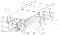
Fig. 1 is a schematic overall structure diagram of an embodiment of the present invention.
Fig. 2 is a partially enlarged view of a portion a in fig. 1.
Fig. 3 is a schematic structural view with a first bed plate removed.
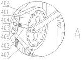
Fig. 4 is a partially enlarged view of fig. 3 at B.
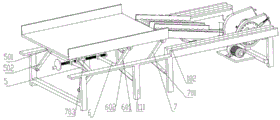
Fig. 5 is a schematic structural diagram in a different working state from fig. 3.
Fig. 6 is a schematic view of the structure with a bottom of the bed plate removed.
Wherein the reference numerals are: 1. a cross beam; 2. a second bed plate; 3. a first bed plate; 4. a crank assembly; 5. a first cylinder; 6. a middle cylinder; 7. a second swing rod; 101. a column; 102. a chute; 103. a trapezoidal chute; 104. a support bar; 105. a fixing plate; 106. a rotating shaft; 107. a rocker; 108. a leg support plate; 109. massage rollers; 110. a baffle plate; 111. erecting a rod; 112. a slider; 401. an eccentric turntable; 402. a gear; 403. a limiting rod; 404. mounting a plate; 405. a cylinder; 406. a spring; 407. a motor; 408. a nut; 501. a first swing rod; 502. a first connecting rod; 601. a middle swing rod; 602. a middle connecting rod; 701. a second connecting rod; 702. a reinforcing rod; 703. a bidirectional screw.
Detailed Description
In order to clearly illustrate the technical features of the present solution, the present solution is explained below by way of specific embodiments.
Referring to fig. 1-6, a passive rehabilitation device for paralyzed patients comprises two opposite and parallel beams 1, wherein the lower parts of the two ends of each beam 1 are respectively provided with an upright post 101, a support rod 104 is arranged between the inner sides of the two upright posts 101 at the same end, a sliding groove 102 with an upward opening is arranged at one half part of the upper end surface of each beam 1, trapezoidal sliding grooves 103 are respectively arranged on the opposite side walls of the two sliding grooves 102, a fixed plate 105 is arranged on the support rod 104 between the trapezoidal sliding grooves 103, a rotating shaft 106 is arranged on the fixed plate 105 through a bearing, both ends of the rotating shaft 106 extend out of the fixed plate 105 and are provided with a crank assembly 4, the crank assembly 4 is connected with a rocker 107, the other end of the rocker 107 is hinged with a sliding block 112, the side wall of the sliding block 112 is provided with a trapezoidal column matched with the trapezoidal sliding groove 103, the trapezoidal, the connecting rod is provided with a leg supporting plate 108, the rotating shaft 106 is connected with a motor 407 with a speed reducer through a transmission mechanism, and the motor 407 is arranged on the fixing plate 105;
the bed plate I is arranged on the sliding groove 102, sliding columns matched with the sliding groove 102 are arranged on two sides below the bed plate I3, the bed plate I3 is located above the leg supporting plate 108, and the bed plate II 2 is arranged above the other half part of the cross beam 1.
The leg supporting plate 108 is provided with baffles 110 on both sides, and the leg supporting plate 108 is provided with a plurality of strip-shaped openings, and massage rollers 109 are arranged in the strip-shaped openings. Because the crank assembly 4 and the rocker 107 drive the leg supporting plate 108 to generate a motion state with one end higher and the other end lower, the massage roller 109 is added, and the leg of the patient can be well massaged by the action of gravity and inertia without adding a power device, so that the blood circulation of the leg is increased while the motion is realized.
The baffle 110 is provided with a plurality of magic tapes. The hook and loop fastener need not be too tight and need to be spaced from the patient's leg, just to avoid the danger of the patient's leg breaking away from the leg rest 108 when the flap 110 is too low.
The crank assembly 4 comprises an eccentric turntable 401, a circular groove is formed in the eccentric turntable 401, a gear 402 is arranged in the circular groove, a screw is arranged at the axis of the inner end face of the gear 402, the screw extends out of the eccentric turntable 401 and is provided with a nut 408, a rocker 107 is arranged on the outer end face of the gear 402, the eccentric turntable 401 is fixedly arranged on the rotating shaft 106, a groove communicated with the circular groove is formed in the eccentric turntable 401, the other end of the groove is opened and is provided with a mounting plate 404, the mounting plate 404 is connected with the eccentric turntable 401 through a screw, a limiting rod 403 is arranged in the groove, the top end of the limiting rod 403 is arranged in a tooth groove of the gear 402, a cylinder 405 is arranged at the bottom end of the limiting rod 403, the cylinder 405 extends out of the mounting plate 404 and is provided with a limiting plate, a spring. Because the condition of patient is different, the swing range that can adapt to is different to the condition of two legs of some patients is also different, consequently set crank assembly 4 to above-mentioned mechanism, can be according to the patient's condition like this, through adjusting gear 402's position and fix through gag lever post 403, can realize two shank layer boards 108 swing range complete unanimity, and the range can be adjusted at will, can also realize in addition that two shank layer boards 108 swing range inequality, and can also adjust wantonly under the prerequisite inequality.
The middle cylinder 6 and the cylinder I5 are further included, the two ends of the cylinder I5 are hinged with the swing rod I501, the cylinder I5 and the outer side of the swing rod I501 are hinged with a connecting rod I502, the two ends of the middle cylinder 6 are hinged with the middle swing rod 601, the middle cylinder 6 and the outer side of the middle swing rod 601 are hinged with a middle connecting rod 602, the middle cylinder further comprises a bidirectional screw rod 703, one end of the bidirectional screw rod 703 is in threaded connection with the middle cylinder 6, the other end of the bidirectional screw rod 703 is in threaded connection with the cylinder I5, a limiting plate is arranged at the outer end of the middle cylinder 703, a rotating handle is arranged at the outer end of the cylinder I5, the swing rod I501, the middle swing rod 601, the connecting rod I502 and;
the top ends of the first swing rod 501 and the middle swing rod 601 are hinged to the side wall of the second bed plate 2, the upright post 111 is arranged below the cross beam 1, the first connecting rod 502 is hinged to the upright post 101, the middle connecting rod 602 is hinged to the upright post 111, and the middle swing rod 601 is close to the first bed plate 3;
the included angle between the middle swing rod 601 and the middle connecting rod 602 is the same as the included angle between the first swing rod 501 and the first connecting rod 502, and the included angles are arranged oppositely.
Because in use, the leg supporting plate 108 is arranged below the bed plate, and the amplitude of swing is increased, the fall between the bed plate and the leg supporting plate 108 is too large, so that the upper body of a patient is uncomfortable, the bed plate 2 is arranged to be capable of being lifted, so that the patient can be adjusted to be at a proper height, and the rotary handle can be driven by manpower or a motor.
The side wall of the second bed board 2 and the outer side of the middle swing rod 601 are hinged with a second swing rod 7, the lower end of the second swing rod 7 is hinged with a second connecting rod 701, the novel bed board further comprises two reinforcing rods 702, one end of each reinforcing rod 702 is hinged between the second swing rod 7 and the second connecting rod 701, the other end of each reinforcing rod 702 is hinged between the middle swing rod 601 and the middle connecting rod 602, the two upright rods 111 are arranged, the second swing rod 7 is hinged on the other upright rod 111, and the stability of the second bed board 2 is.
Two sides of the second bed board 2 are provided with protection plates. The guard plate plays certain guard action to the patient, and in order to make the patient more comfortable, bed board two 2 can be formed by two board articulations to realize the effect that inclination can be adjusted, can reference prior art. The second bed board 2 can also be provided with a drain outlet.
The using mode can be that bed board 3 and bed board two 2 can regard as the bed to use at ordinary times, when needs carry out shank rehabilitation training, can take out bed board 3 from spout 102, then according to patient's actual conditions, adjust two nuts 408 respectively, pull down gag lever post 403, make gag lever post 403 break away from the tooth's socket, manual rotating gear 402, when reaching suitable position, gag lever post 403 resets, screw up nut 408, rotate two-way screw rod 703, so that the position of adjusting bed board two 2, reach suitable position after, put patient's leg on leg layer board 108, motor 407 is started, carry out the leg motion.
The technical features of the present invention which are not described in the above embodiments may be implemented by or using the prior art, and are not described herein again, of course, the above description is not intended to limit the present invention, and the present invention is not limited to the above examples, and variations, modifications, additions or substitutions which may be made by those skilled in the art within the spirit and scope of the present invention should also fall within the protection scope of the present invention.
Claims (7)
1. A passive rehabilitation device for paralyzed patients is characterized by comprising two opposite and parallel beams, wherein stand columns are arranged below the two ends of each beam, a support rod is arranged between the inner sides of the two stand columns at the same end, a sliding groove with an upward opening is arranged at one half part of the upper end surfaces of the two beams, trapezoidal sliding grooves are arranged on the opposite side walls of the two sliding grooves, a fixed plate is arranged on the support rod between the trapezoidal sliding grooves, a rotating shaft is arranged on the fixed plate through a bearing, the two ends of the rotating shaft extend out of the fixed plate and are provided with crank assemblies, the crank assemblies are connected with rockers, the other ends of the rockers are hinged with sliding blocks, trapezoidal columns matched with the trapezoidal sliding grooves are arranged on the side walls of the sliding blocks, the trapezoidal columns are arranged in the trapezoidal sliding grooves, and connecting rods are arranged in the middle positions of the upper end surfaces, the connecting rod is provided with a leg supporting plate, the rotating shaft is connected with a motor with a speed reducer through a transmission mechanism, and the motor is arranged on the fixing plate;
the leg support plate is characterized by further comprising a first bed plate arranged on the sliding groove, sliding columns matched with the sliding groove are arranged on two sides of the lower portion of the first bed plate, the first bed plate is located above the leg support plate, and a second bed plate is arranged above the other half portion of the cross beam.
2. The passive rehabilitation device for paralyzed patients according to claim 1, wherein baffles are arranged on both sides of the leg supporting plate, a plurality of strip-shaped openings are arranged on the leg supporting plate, and massage rollers are arranged in the strip-shaped openings.
3. The passive rehabilitation apparatus for paralyzed patients according to claim 2, wherein a plurality of magic tapes are disposed on the baffle plate.
4. The passive rehabilitation device for paralyzed patients according to claim 1, wherein the crank assembly comprises an eccentric turntable, a circular groove is arranged on the eccentric turntable, a gear is arranged in the circular groove, a screw rod is arranged at the axis of the inner end surface of the gear, the screw rod extends out of the eccentric turntable and is provided with a nut, the rocker is arranged on the outer end surface of the gear, the eccentric turntable is fixedly arranged on the rotating shaft, a groove communicated with the circular groove is formed in the eccentric turntable, the other end of the groove is opened and is provided with a mounting plate, the mounting plate is connected with the eccentric turntable through a screw, a limiting rod is arranged in the groove, the top end of the limiting rod is arranged in the groove of the gear, a cylinder is arranged at the bottom end of the limiting rod, the cylinder extends out of the mounting plate and is provided with a limiting plate, the cylinder is sleeved with a spring, one end of the spring is fixed on the mounting plate, and the other end of the spring is fixed on the limiting rod.
5. The passive rehabilitation device for the paralyzed patient according to claim 1, further comprising a middle cylinder and a first cylinder, wherein two ends of the first cylinder are hinged with a first swing rod, a first connecting rod is hinged on the first cylinder and positioned on the outer side of the first swing rod, two ends of the middle cylinder are hinged with a middle swing rod, a middle connecting rod is hinged on the middle cylinder and positioned on the outer side of the middle swing rod, the passive rehabilitation device further comprises a bidirectional screw rod, one end of the bidirectional screw rod is in threaded connection with the middle cylinder, the other end of the bidirectional screw rod is in threaded connection with the first cylinder, a limiting plate is arranged at the outer end of the middle cylinder, a rotating handle is arranged at the outer end of the first cylinder, the first swing rod, the middle swing rod, the first connecting rod and the middle connecting rod are the same, and the middle cylinder and the first;
the top ends of the first swing rod and the middle swing rod are hinged to the side wall of the second bed plate, an upright post is arranged below the cross beam, the first connecting rod is hinged to the upright post, the middle connecting rod is hinged to the upright post, and the middle swing rod is close to the first bed plate;
the included angle between the middle swing rod and the middle connecting rod is the same as the included angle between the first swing rod and the first connecting rod, and the included angles are oppositely arranged.
6. The passive rehabilitation device for the paralyzed patient according to claim 5, wherein a second swing rod is hinged on the side wall of the second bed plate and positioned on the outer side of the middle swing rod, a second connecting rod is hinged at the lower end of the second swing rod, the passive rehabilitation device further comprises a reinforcing rod, one end of the reinforcing rod is hinged between the second swing rod and the second connecting rod, the other end of the reinforcing rod is hinged between the middle swing rod and the middle connecting rod, two vertical rods are arranged, and the second swing rod is hinged on the other vertical rod.
7. The passive rehabilitation device for the paralyzed patient according to claim 1, wherein two sides of the second bed plate are provided with protection plates.
Priority Applications (1)
| Application Number | Priority Date | Filing Date | Title |
|---|---|---|---|
| CN201910724657.5A CN110314070B (en) | 2019-08-07 | 2019-08-07 | Passive rehabilitation device for paralytic patient |
Applications Claiming Priority (1)
| Application Number | Priority Date | Filing Date | Title |
|---|---|---|---|
| CN201910724657.5A CN110314070B (en) | 2019-08-07 | 2019-08-07 | Passive rehabilitation device for paralytic patient |
Publications (2)
| Publication Number | Publication Date |
|---|---|
| CN110314070A CN110314070A (en) | 2019-10-11 |
| CN110314070B true CN110314070B (en) | 2021-06-22 |
Family
ID=68125569
Family Applications (1)
| Application Number | Title | Priority Date | Filing Date |
|---|---|---|---|
| CN201910724657.5A Expired - Fee Related CN110314070B (en) | 2019-08-07 | 2019-08-07 | Passive rehabilitation device for paralytic patient |
Country Status (1)
| Country | Link |
|---|---|
| CN (1) | CN110314070B (en) |
Families Citing this family (3)
| Publication number | Priority date | Publication date | Assignee | Title |
|---|---|---|---|---|
| CN111013102B (en) * | 2020-02-26 | 2024-08-23 | 日照市中医医院 | Rehabilitation device for postpartum use |
| CN112022536B (en) * | 2020-08-11 | 2021-07-13 | 常州工学院 | Swinging mechanism of old-people bed |
| CN113057846B (en) * | 2020-09-25 | 2022-08-09 | 江西应用科技学院 | Horizontal upper limb rehabilitation physiotherapy method and device |
Citations (5)
| Publication number | Priority date | Publication date | Assignee | Title |
|---|---|---|---|---|
| CN201001827Y (en) * | 2006-12-13 | 2008-01-09 | 李砂 | Multifunctional sport recovery bed |
| CN105250093A (en) * | 2015-11-14 | 2016-01-20 | 霍进铭 | Automatic rehabilitation nursing bed driven by linear motor |
| US20160016036A1 (en) * | 2014-05-18 | 2016-01-21 | Andrew Bruce Barriskill | Supine cycle |
| CN106137607A (en) * | 2016-08-15 | 2016-11-23 | 深圳市顺利普科技有限公司 | Recovery bed |
| CN108186315A (en) * | 2018-01-24 | 2018-06-22 | 李建云 | A kind of patient's rehabilitation massage bed |
-
2019
- 2019-08-07 CN CN201910724657.5A patent/CN110314070B/en not_active Expired - Fee Related
Patent Citations (5)
| Publication number | Priority date | Publication date | Assignee | Title |
|---|---|---|---|---|
| CN201001827Y (en) * | 2006-12-13 | 2008-01-09 | 李砂 | Multifunctional sport recovery bed |
| US20160016036A1 (en) * | 2014-05-18 | 2016-01-21 | Andrew Bruce Barriskill | Supine cycle |
| CN105250093A (en) * | 2015-11-14 | 2016-01-20 | 霍进铭 | Automatic rehabilitation nursing bed driven by linear motor |
| CN106137607A (en) * | 2016-08-15 | 2016-11-23 | 深圳市顺利普科技有限公司 | Recovery bed |
| CN108186315A (en) * | 2018-01-24 | 2018-06-22 | 李建云 | A kind of patient's rehabilitation massage bed |
Also Published As
| Publication number | Publication date |
|---|---|
| CN110314070A (en) | 2019-10-11 |
Similar Documents
| Publication | Publication Date | Title |
|---|---|---|
| CN110314070B (en) | Passive rehabilitation device for paralytic patient | |
| CN202505695U (en) | Passive exerciser for limbs | |
| CN210447971U (en) | Cardiothoracic surgery nursing is with taking exercise rehabilitation device | |
| CN109700635A (en) | Auxiliary device is used in a kind of exercise of orthopedic rehabilitation | |
| CN206777438U (en) | It is a kind of for orthopedic spinal treatment and rehabilitation it is function bed | |
| CN109223443A (en) | A kind of rheumatism device for healing and training | |
| CN108354806A (en) | A kind of orthopaedics patient rehabilitation leg exercises device | |
| CN109620636A (en) | A kind of Cardiological Rehabilitation care training device | |
| CN111110515A (en) | Waist is with multi-functional rehabilitation training device | |
| CN107583235A (en) | A kind of new construction before apparatus body-building is warmed up, stretching device | |
| CN207462557U (en) | A kind of new construction before instrument body-building is warmed up, stretching device | |
| CN210933594U (en) | Cardiovascular patient assists recovered equipment | |
| CN112473080A (en) | Multifunctional lower limb rehabilitation training bed | |
| CN115670835B (en) | Neural rehabilitation training device | |
| CN201175397Y (en) | Cervical vertebra remedy physiotherapy device | |
| CN110314069B (en) | Cerebral thrombosis patient uses rehabilitation device | |
| CN209392360U (en) | A kind of Neurology spasm therapeutic device | |
| CN106512304A (en) | Upright waist twisting machine | |
| CN113599180A (en) | Osteonecrosis postoperative rehabilitation tempers device | |
| CN208049263U (en) | A kind of orthopedic rehabilitation device | |
| CN105853179A (en) | Brain ultrasonic massage robot for neurology department | |
| CN111939003A (en) | Lower limb rehabilitation robot | |
| CN214971524U (en) | Uropoiesis patient postoperative low limbs exercise device | |
| CN220309371U (en) | Rehabilitation training device for clinical medicine | |
| CN215132724U (en) | Medical treatment is with patient ankle telecontrol equipment |
Legal Events
| Date | Code | Title | Description |
|---|---|---|---|
| PB01 | Publication | ||
| PB01 | Publication | ||
| SE01 | Entry into force of request for substantive examination | ||
| SE01 | Entry into force of request for substantive examination | ||
| GR01 | Patent grant | ||
| GR01 | Patent grant | ||
| CF01 | Termination of patent right due to non-payment of annual fee | ||
| CF01 | Termination of patent right due to non-payment of annual fee |
Granted publication date: 20210622 |