CN110267627B - Systems, devices, and methods for accurately deploying implants in the prostatic urethra - Google Patents
Systems, devices, and methods for accurately deploying implants in the prostatic urethra Download PDFInfo
- Publication number
- CN110267627B CN110267627B CN201780086171.2A CN201780086171A CN110267627B CN 110267627 B CN110267627 B CN 110267627B CN 201780086171 A CN201780086171 A CN 201780086171A CN 110267627 B CN110267627 B CN 110267627B
- Authority
- CN
- China
- Prior art keywords
- implant
- distal
- proximal
- control
- gear
- Prior art date
- Legal status (The legal status is an assumption and is not a legal conclusion. Google has not performed a legal analysis and makes no representation as to the accuracy of the status listed.)
- Active
Links
- 239000007943 implant Substances 0.000 title claims abstract description 222
- 210000003708 urethra Anatomy 0.000 title claims abstract description 37
- 238000000034 method Methods 0.000 title abstract description 32
- 230000033001 locomotion Effects 0.000 claims description 58
- 238000004873 anchoring Methods 0.000 claims description 5
- 238000003780 insertion Methods 0.000 abstract description 3
- 230000037431 insertion Effects 0.000 abstract description 3
- 230000007246 mechanism Effects 0.000 description 29
- 230000000284 resting effect Effects 0.000 description 13
- 238000003384 imaging method Methods 0.000 description 12
- 210000003484 anatomy Anatomy 0.000 description 10
- 238000005286 illumination Methods 0.000 description 9
- 230000007704 transition Effects 0.000 description 8
- 238000010586 diagram Methods 0.000 description 5
- 230000036961 partial effect Effects 0.000 description 5
- 238000004804 winding Methods 0.000 description 5
- 210000001519 tissue Anatomy 0.000 description 4
- 206010004446 Benign prostatic hyperplasia Diseases 0.000 description 3
- 208000004403 Prostatic Hyperplasia Diseases 0.000 description 3
- 230000008901 benefit Effects 0.000 description 3
- 239000012530 fluid Substances 0.000 description 3
- 230000002028 premature Effects 0.000 description 3
- 230000008569 process Effects 0.000 description 3
- 230000002441 reversible effect Effects 0.000 description 3
- 238000006467 substitution reaction Methods 0.000 description 3
- 206010003591 Ataxia Diseases 0.000 description 2
- 206010005003 Bladder cancer Diseases 0.000 description 2
- 206010061876 Obstruction Diseases 0.000 description 2
- 206010060862 Prostate cancer Diseases 0.000 description 2
- 208000000236 Prostatic Neoplasms Diseases 0.000 description 2
- FAPWRFPIFSIZLT-UHFFFAOYSA-M Sodium chloride Chemical compound [Na+].[Cl-] FAPWRFPIFSIZLT-UHFFFAOYSA-M 0.000 description 2
- 206010065584 Urethral stenosis Diseases 0.000 description 2
- 208000007097 Urinary Bladder Neoplasms Diseases 0.000 description 2
- 206010061397 Urinary tract injury Diseases 0.000 description 2
- 208000027418 Wounds and injury Diseases 0.000 description 2
- 230000000994 depressogenic effect Effects 0.000 description 2
- 230000002262 irrigation Effects 0.000 description 2
- 238000003973 irrigation Methods 0.000 description 2
- 230000000670 limiting effect Effects 0.000 description 2
- 230000003211 malignant effect Effects 0.000 description 2
- 238000012986 modification Methods 0.000 description 2
- 230000004048 modification Effects 0.000 description 2
- 238000012634 optical imaging Methods 0.000 description 2
- 238000003825 pressing Methods 0.000 description 2
- 201000007094 prostatitis Diseases 0.000 description 2
- 239000011780 sodium chloride Substances 0.000 description 2
- 210000005070 sphincter Anatomy 0.000 description 2
- 230000000087 stabilizing effect Effects 0.000 description 2
- 238000013519 translation Methods 0.000 description 2
- 238000012285 ultrasound imaging Methods 0.000 description 2
- 201000001988 urethral stricture Diseases 0.000 description 2
- 201000005112 urinary bladder cancer Diseases 0.000 description 2
- 238000012800 visualization Methods 0.000 description 2
- 206010046555 Urinary retention Diseases 0.000 description 1
- 230000009471 action Effects 0.000 description 1
- 239000000654 additive Substances 0.000 description 1
- 230000000996 additive effect Effects 0.000 description 1
- 230000000712 assembly Effects 0.000 description 1
- 238000000429 assembly Methods 0.000 description 1
- 238000005452 bending Methods 0.000 description 1
- 210000004903 cardiac system Anatomy 0.000 description 1
- 230000008859 change Effects 0.000 description 1
- 230000000295 complement effect Effects 0.000 description 1
- 238000013270 controlled release Methods 0.000 description 1
- 230000008878 coupling Effects 0.000 description 1
- 238000010168 coupling process Methods 0.000 description 1
- 238000005859 coupling reaction Methods 0.000 description 1
- 238000002716 delivery method Methods 0.000 description 1
- 238000013461 design Methods 0.000 description 1
- 230000000694 effects Effects 0.000 description 1
- 238000001125 extrusion Methods 0.000 description 1
- 238000002594 fluoroscopy Methods 0.000 description 1
- 210000001035 gastrointestinal tract Anatomy 0.000 description 1
- 210000002216 heart Anatomy 0.000 description 1
- 238000002513 implantation Methods 0.000 description 1
- 238000002347 injection Methods 0.000 description 1
- 239000007924 injection Substances 0.000 description 1
- 208000014674 injury Diseases 0.000 description 1
- 210000000936 intestine Anatomy 0.000 description 1
- 230000007794 irritation Effects 0.000 description 1
- 210000003734 kidney Anatomy 0.000 description 1
- 239000007788 liquid Substances 0.000 description 1
- 210000004185 liver Anatomy 0.000 description 1
- 238000004519 manufacturing process Methods 0.000 description 1
- 239000000463 material Substances 0.000 description 1
- 230000003287 optical effect Effects 0.000 description 1
- 210000000496 pancreas Anatomy 0.000 description 1
- 230000002685 pulmonary effect Effects 0.000 description 1
- 230000002829 reductive effect Effects 0.000 description 1
- 238000007493 shaping process Methods 0.000 description 1
- 239000007787 solid Substances 0.000 description 1
- 210000000952 spleen Anatomy 0.000 description 1
- 210000002784 stomach Anatomy 0.000 description 1
- 239000000725 suspension Substances 0.000 description 1
- 230000008733 trauma Effects 0.000 description 1
- 210000001635 urinary tract Anatomy 0.000 description 1
- 210000005166 vasculature Anatomy 0.000 description 1
Images


Classifications
-
- A—HUMAN NECESSITIES
- A61—MEDICAL OR VETERINARY SCIENCE; HYGIENE
- A61F—FILTERS IMPLANTABLE INTO BLOOD VESSELS; PROSTHESES; DEVICES PROVIDING PATENCY TO, OR PREVENTING COLLAPSING OF, TUBULAR STRUCTURES OF THE BODY, e.g. STENTS; ORTHOPAEDIC, NURSING OR CONTRACEPTIVE DEVICES; FOMENTATION; TREATMENT OR PROTECTION OF EYES OR EARS; BANDAGES, DRESSINGS OR ABSORBENT PADS; FIRST-AID KITS
- A61F2/00—Filters implantable into blood vessels; Prostheses, i.e. artificial substitutes or replacements for parts of the body; Appliances for connecting them with the body; Devices providing patency to, or preventing collapsing of, tubular structures of the body, e.g. stents
- A61F2/02—Prostheses implantable into the body
- A61F2/04—Hollow or tubular parts of organs, e.g. bladders, tracheae, bronchi or bile ducts
- A61F2/042—Urinary bladders
-
- A—HUMAN NECESSITIES
- A61—MEDICAL OR VETERINARY SCIENCE; HYGIENE
- A61F—FILTERS IMPLANTABLE INTO BLOOD VESSELS; PROSTHESES; DEVICES PROVIDING PATENCY TO, OR PREVENTING COLLAPSING OF, TUBULAR STRUCTURES OF THE BODY, e.g. STENTS; ORTHOPAEDIC, NURSING OR CONTRACEPTIVE DEVICES; FOMENTATION; TREATMENT OR PROTECTION OF EYES OR EARS; BANDAGES, DRESSINGS OR ABSORBENT PADS; FIRST-AID KITS
- A61F2/00—Filters implantable into blood vessels; Prostheses, i.e. artificial substitutes or replacements for parts of the body; Appliances for connecting them with the body; Devices providing patency to, or preventing collapsing of, tubular structures of the body, e.g. stents
- A61F2/82—Devices providing patency to, or preventing collapsing of, tubular structures of the body, e.g. stents
- A61F2/86—Stents in a form characterised by the wire-like elements; Stents in the form characterised by a net-like or mesh-like structure
- A61F2/88—Stents in a form characterised by the wire-like elements; Stents in the form characterised by a net-like or mesh-like structure the wire-like elements formed as helical or spiral coils
- A61F2/885—Stents in a form characterised by the wire-like elements; Stents in the form characterised by a net-like or mesh-like structure the wire-like elements formed as helical or spiral coils comprising a coil including a plurality of spiral or helical sections with alternate directions around a central axis
-
- A—HUMAN NECESSITIES
- A61—MEDICAL OR VETERINARY SCIENCE; HYGIENE
- A61B—DIAGNOSIS; SURGERY; IDENTIFICATION
- A61B17/00—Surgical instruments, devices or methods, e.g. tourniquets
- A61B17/34—Trocars; Puncturing needles
- A61B17/3468—Trocars; Puncturing needles for implanting or removing devices, e.g. prostheses, implants, seeds, wires
-
- A—HUMAN NECESSITIES
- A61—MEDICAL OR VETERINARY SCIENCE; HYGIENE
- A61F—FILTERS IMPLANTABLE INTO BLOOD VESSELS; PROSTHESES; DEVICES PROVIDING PATENCY TO, OR PREVENTING COLLAPSING OF, TUBULAR STRUCTURES OF THE BODY, e.g. STENTS; ORTHOPAEDIC, NURSING OR CONTRACEPTIVE DEVICES; FOMENTATION; TREATMENT OR PROTECTION OF EYES OR EARS; BANDAGES, DRESSINGS OR ABSORBENT PADS; FIRST-AID KITS
- A61F2/00—Filters implantable into blood vessels; Prostheses, i.e. artificial substitutes or replacements for parts of the body; Appliances for connecting them with the body; Devices providing patency to, or preventing collapsing of, tubular structures of the body, e.g. stents
- A61F2/02—Prostheses implantable into the body
- A61F2/04—Hollow or tubular parts of organs, e.g. bladders, tracheae, bronchi or bile ducts
-
- A—HUMAN NECESSITIES
- A61—MEDICAL OR VETERINARY SCIENCE; HYGIENE
- A61F—FILTERS IMPLANTABLE INTO BLOOD VESSELS; PROSTHESES; DEVICES PROVIDING PATENCY TO, OR PREVENTING COLLAPSING OF, TUBULAR STRUCTURES OF THE BODY, e.g. STENTS; ORTHOPAEDIC, NURSING OR CONTRACEPTIVE DEVICES; FOMENTATION; TREATMENT OR PROTECTION OF EYES OR EARS; BANDAGES, DRESSINGS OR ABSORBENT PADS; FIRST-AID KITS
- A61F2/00—Filters implantable into blood vessels; Prostheses, i.e. artificial substitutes or replacements for parts of the body; Appliances for connecting them with the body; Devices providing patency to, or preventing collapsing of, tubular structures of the body, e.g. stents
- A61F2/95—Instruments specially adapted for placement or removal of stents or stent-grafts
- A61F2/9517—Instruments specially adapted for placement or removal of stents or stent-grafts handle assemblies therefor
-
- A—HUMAN NECESSITIES
- A61—MEDICAL OR VETERINARY SCIENCE; HYGIENE
- A61F—FILTERS IMPLANTABLE INTO BLOOD VESSELS; PROSTHESES; DEVICES PROVIDING PATENCY TO, OR PREVENTING COLLAPSING OF, TUBULAR STRUCTURES OF THE BODY, e.g. STENTS; ORTHOPAEDIC, NURSING OR CONTRACEPTIVE DEVICES; FOMENTATION; TREATMENT OR PROTECTION OF EYES OR EARS; BANDAGES, DRESSINGS OR ABSORBENT PADS; FIRST-AID KITS
- A61F2/00—Filters implantable into blood vessels; Prostheses, i.e. artificial substitutes or replacements for parts of the body; Appliances for connecting them with the body; Devices providing patency to, or preventing collapsing of, tubular structures of the body, e.g. stents
- A61F2/95—Instruments specially adapted for placement or removal of stents or stent-grafts
- A61F2/962—Instruments specially adapted for placement or removal of stents or stent-grafts having an outer sleeve
- A61F2/966—Instruments specially adapted for placement or removal of stents or stent-grafts having an outer sleeve with relative longitudinal movement between outer sleeve and prosthesis, e.g. using a push rod
-
- A—HUMAN NECESSITIES
- A61—MEDICAL OR VETERINARY SCIENCE; HYGIENE
- A61B—DIAGNOSIS; SURGERY; IDENTIFICATION
- A61B17/00—Surgical instruments, devices or methods, e.g. tourniquets
- A61B17/00234—Surgical instruments, devices or methods, e.g. tourniquets for minimally invasive surgery
- A61B2017/00238—Type of minimally invasive operation
- A61B2017/00274—Prostate operation, e.g. prostatectomy, turp, bhp treatment
-
- A—HUMAN NECESSITIES
- A61—MEDICAL OR VETERINARY SCIENCE; HYGIENE
- A61F—FILTERS IMPLANTABLE INTO BLOOD VESSELS; PROSTHESES; DEVICES PROVIDING PATENCY TO, OR PREVENTING COLLAPSING OF, TUBULAR STRUCTURES OF THE BODY, e.g. STENTS; ORTHOPAEDIC, NURSING OR CONTRACEPTIVE DEVICES; FOMENTATION; TREATMENT OR PROTECTION OF EYES OR EARS; BANDAGES, DRESSINGS OR ABSORBENT PADS; FIRST-AID KITS
- A61F2/00—Filters implantable into blood vessels; Prostheses, i.e. artificial substitutes or replacements for parts of the body; Appliances for connecting them with the body; Devices providing patency to, or preventing collapsing of, tubular structures of the body, e.g. stents
- A61F2/02—Prostheses implantable into the body
- A61F2/04—Hollow or tubular parts of organs, e.g. bladders, tracheae, bronchi or bile ducts
- A61F2002/047—Urethrae
-
- A—HUMAN NECESSITIES
- A61—MEDICAL OR VETERINARY SCIENCE; HYGIENE
- A61F—FILTERS IMPLANTABLE INTO BLOOD VESSELS; PROSTHESES; DEVICES PROVIDING PATENCY TO, OR PREVENTING COLLAPSING OF, TUBULAR STRUCTURES OF THE BODY, e.g. STENTS; ORTHOPAEDIC, NURSING OR CONTRACEPTIVE DEVICES; FOMENTATION; TREATMENT OR PROTECTION OF EYES OR EARS; BANDAGES, DRESSINGS OR ABSORBENT PADS; FIRST-AID KITS
- A61F2250/00—Special features of prostheses classified in groups A61F2/00 - A61F2/26 or A61F2/82 or A61F9/00 or A61F11/00 or subgroups thereof
- A61F2250/0004—Special features of prostheses classified in groups A61F2/00 - A61F2/26 or A61F2/82 or A61F9/00 or A61F11/00 or subgroups thereof adjustable
- A61F2250/001—Special features of prostheses classified in groups A61F2/00 - A61F2/26 or A61F2/82 or A61F9/00 or A61F11/00 or subgroups thereof adjustable for adjusting a diameter
-
- F—MECHANICAL ENGINEERING; LIGHTING; HEATING; WEAPONS; BLASTING
- F16—ENGINEERING ELEMENTS AND UNITS; GENERAL MEASURES FOR PRODUCING AND MAINTAINING EFFECTIVE FUNCTIONING OF MACHINES OR INSTALLATIONS; THERMAL INSULATION IN GENERAL
- F16H—GEARING
- F16H1/00—Toothed gearings for conveying rotary motion
- F16H1/02—Toothed gearings for conveying rotary motion without gears having orbital motion
- F16H1/04—Toothed gearings for conveying rotary motion without gears having orbital motion involving only two intermeshing members
- F16H1/06—Toothed gearings for conveying rotary motion without gears having orbital motion involving only two intermeshing members with parallel axes
-
- F—MECHANICAL ENGINEERING; LIGHTING; HEATING; WEAPONS; BLASTING
- F16—ENGINEERING ELEMENTS AND UNITS; GENERAL MEASURES FOR PRODUCING AND MAINTAINING EFFECTIVE FUNCTIONING OF MACHINES OR INSTALLATIONS; THERMAL INSULATION IN GENERAL
- F16H—GEARING
- F16H1/00—Toothed gearings for conveying rotary motion
- F16H1/28—Toothed gearings for conveying rotary motion with gears having orbital motion
Abstract
Systems, devices, and methods for delivering implants into the prostatic urethra are provided. Embodiments of the delivery system may include a delivery device for insertion into a patient and a proximal control device for controlling release of the implant from the delivery device.
Description
Cross Reference to Related Applications
The present application claims priority and benefit from U.S. provisional application Ser. No. 62/432,542 filed on Ser. No. 12/9 of 2016, the contents of which are incorporated herein by reference in their entirety for all purposes.
Technical Field
The subject matter described herein relates to systems, devices, and methods for delivering or deploying implants into the prostatic urethra, and more particularly to atraumatic and minimally invasive delivery through tortuous bends of the male urethra.
Background
There are numerous clinical reasons for placing implants into the prostatic urethra, such as for treating urinary retention associated with Benign Prostatic Hyperplasia (BPH), obstruction caused by prostate cancer, bladder cancer, urinary tract injury, prostatitis, bladder sphincter dyssynergia, benign or malignant urethral stricture, and other conditions for which treatment is desired. Accurate and consistent placement of implants into the prostatic urethral cavity has proven challenging due to the naturally complex and tortuous anatomical geometries, patient-to-patient geometric and tissue differences, and anatomical limitations associated with those conditions. Furthermore, there are complex challenges in the design and/or manufacture of systems with sufficient flexibility for delivering such implants in a minimally invasive manner. For these and other reasons, there is a need for improved systems, devices, and methods for delivering implants to the prostatic urethra.
Disclosure of Invention
Provided herein are many example embodiments of delivery systems and related methods for delivering or deploying implants within a repaired urethra or other body part. Embodiments of the delivery system may include: a delivery device insertable into the repaired urethra; and a proximal control device coupled with the delivery device and configured to control deployment of one or more implants from the delivery device. In some embodiments, the delivery device may include a plurality of tubular members, each having various functions described in more detail herein. Various embodiments of implants for use with the delivery system are also described.
Other systems, devices, methods, features and advantages of the subject matter described herein will be or become apparent to one with skill in the art upon examination of the following figures and detailed description. It is intended that all such additional systems, methods, features and advantages be included within this description, be within the scope of the subject matter described herein, and be protected by the accompanying claims. The features of the exemplary embodiments should in no way be construed as limiting the appended claims, which are not explicitly recited in the claims.
Drawings
Details of the subject matter set forth herein (both as to its structure and operation) may be apparent from a study of the accompanying drawings, in which like reference numerals refer to like parts. The components in the drawings are not necessarily to scale, emphasis instead being placed upon illustrating the principles of the subject matter. Moreover, all illustrations are intended to convey concepts, wherein relative sizes, shapes, and other detailed attributes may be illustrated schematically rather than literally or precisely.
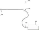
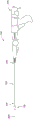
Fig. 1A is a block diagram depicting an example embodiment of a delivery system.
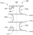
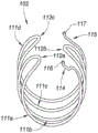
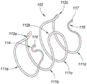
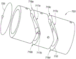
Fig. 1B, 1C, and 1D are side, end, and perspective views, respectively, depicting an example embodiment of an implant.
Fig. 2A-2H are perspective views depicting an example embodiment of a delivery system in different stages of deployment of an implant.
Fig. 3A-3C are perspective views depicting an example embodiment of a gripper assembly in use within a delivery system.
Fig. 4A-4J are partial cross-sectional views depicting example embodiments of an anchor delivery member of a delivery system.
Fig. 5A-5B are side views depicting an example embodiment of a delivery system in various stages of deployment of an implant.
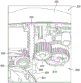
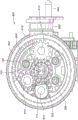
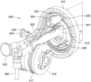
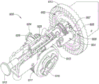
Fig. 6A and 6B are an interior side view and an interior perspective view, respectively, depicting an example embodiment of a proximal control.
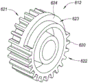
Fig. 6C is a perspective view depicting an example embodiment of a gear for use with a delivery system.
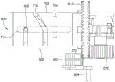
Fig. 7A is an interior top down view depicting an example embodiment of components of a proximal control.
Fig. 7B is a perspective view depicting an example embodiment of a cam.
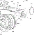
FIG. 8 is an interior side view depicting an example embodiment of a gear assembly.
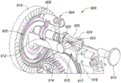
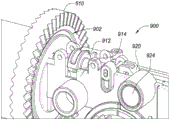
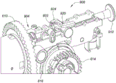
Fig. 9A-9F are interior perspective views depicting example embodiments of components of a proximal control.
Fig. 10A is a flow chart depicting an example embodiment of a method for delivering an implant.
Fig. 10B is a timing diagram depicting an example embodiment of a sequence of steps for deploying an implant.
Detailed Description
Before the present subject matter is described in detail, it is to be understood that this disclosure is not limited to particular embodiments described, as such may, of course, vary. It is also to be understood that the terminology used herein is for the purpose of describing particular embodiments only, and is not intended to be limiting, since the scope of the present disclosure will be limited only by the appended claims.
The subject matter presented herein is described in the context of delivery or deployment of one or more implants within the prostatic urethra. The purpose for deploying the implant(s) in the prostatic urethra may vary. The embodiments described herein are particularly suited for treating BPH, but they are not limited thereto. Other conditions in which these embodiments may be used include, but are not limited to, treatment of obstruction caused by prostate cancer, bladder cancer, urinary tract injury, prostatitis, bladder sphincter dyssynergia, and/or benign or malignant urethral stricture. Furthermore, these embodiments may have applicability for deploying one or more implants in other locations of the urinary tract or in the bladder and other biological cavities, cavities or spaces, such as the human vasculature, cardiac system, pulmonary system, or gastrointestinal tract, including locations within the heart, stomach, intestines, liver, spleen, pancreas, and kidneys.
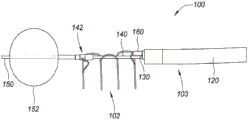
Fig. 1A is a block diagram depicting an example embodiment of a delivery system 100 having an elongate delivery device 103 coupled to a proximal control device 200. The distal region 104 is adapted for insertion into the patient's urethra (or other cavity or body cavity of the patient) through the urethral orifice. The distal region 104 preferably has an atraumatic configuration (e.g., relatively soft and rounded) to minimize irritation or trauma to the patient. The elongate delivery device 103 carries or accommodates one or more implants 102 (not shown) for delivery or deployment within or adjacent to the prostatic urethra. The proximal region 105 of the delivery device 103 is coupled with a proximal control device 200, the proximal control device 200 being maintained external to the patient's body and configured to be used by a physician or other healthcare professional to control delivery of one or more implants 102.
Example embodiments of delivery devices and related methods
Fig. 1B, 1C, and 1D are side, end, and perspective views, respectively, depicting an example embodiment of an implant 102 in a resting configuration. The implantable device 102 is biased toward the resting configuration depicted herein and is deformable between a resting configuration and a relatively more elongated receiving (or delivery) configuration for receiving the implant 102 within the delivery device 103 (see, e.g., fig. 3A). The receiving configuration may be a straight or linear state with minimal curvature. The resting configuration has a relatively greater lateral width and a relatively shorter longitudinal length than the receiving configuration. Upon exiting the open end of the delivery device 103, the implant 102 freely converts its shape back to the shape of the resting configuration, although the constraints imposed by the patient's urethral wall may prevent the implant 102 from fully reaching the resting configuration. Since the implant 102 is biased toward the resting configuration, the implant 102 is configured to self-expand when unconstrained by the delivery device 103 and may be referred to as "self-expanding". The shape of the implant 102 in its deployed state within, for example, a patient's urethra may be referred to as a deployed configuration, and will often be a shape deformed from a resting configuration by surrounding tissue, although the deployed configuration may be the same as the resting configuration.
The implant 102 may be constructed in a number of different ways, including any or all of those implant configurations described in U.S. patent publication No. 20150257908 and/or international publication No. WO 2017/18887, both of which are incorporated herein by reference for all purposes.
The loop structure 111 is configured to maintain the urethra in a fully or partially open state when inflated from the containment configuration. The device 100 can be manufactured in a variety of sizes as desired such that the width (e.g., diameter) of each annular structure 111 is slightly greater than the width of the urethra and the length of each interconnect 112 determines the spacing between the annular structures 111. The annular structures 111 may have the same or different widths. For example, in the embodiment depicted herein, annular structure 111a has a relatively smaller width than structures 111 b-111 d having the same width. This can accommodate the prostatic urethra, which converges to a smaller geometry before the bladder neck.
Each annular structure 111 may lie or exist in a single plane, and in some embodiments, the single plane may be oriented with the normal axis perpendicular to the central passage 124 of the implant 102 (as depicted in fig. 1B). In other embodiments, the annular structure 111 may lie in multiple planes. The annular structure 111 may extend about the central axis 126 to form a complete circle (e.g., 360 degrees of rotation), or may form less than a complete circle (e.g., less than 360 degrees) as shown herein. Although not limited thereto, in many embodiments, the annular structure 111 extends between 270 degrees and 360 degrees.
As can be seen from fig. 1B-1D, the geometry of the implant 102 may have a cylindrical or substantially cylindrical profile with a circular or oval cross-section. In other embodiments, the implant 102 may have a prismatic or substantially prismatic shape with a triangular or substantially triangular cross-section, or may have other shapes.
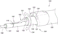
The delivery device 103 may include one or more elongate flexible members (e.g., 120, 130, 140, and 150 as described below), each having one or more lumens. The one or more elongated flexible members of the delivery device 103 may be solid or non-hollow members without lumens. Fig. 2A is a perspective view depicting an example embodiment of the distal end region 104 of the delivery device 103. In this embodiment, the delivery device 103 includes a first elongate tubular member 120, a second elongate tubular member 130, a third elongate tubular member 140, and a fourth elongate tubular member 150. The delivery device 103 may vary and may include more or fewer tubular members in other embodiments.
In this embodiment, the first elongate tubular member 120 is the outermost tubular member and is flexible, but provides support for the members contained therein. The first tubular member 120 is referred to herein as an outer shaft 120 and may have one or more lumens. In this embodiment, the outer shaft 120 includes a first lumen 121 that houses a second elongate tubular member 130, referred to herein as the inner shaft 130. The outer shaft 120 and the inner shaft 130 are each controllable independently of the other. The inner shaft 130 can slide distally and proximally within the lumen 121, and is shown here as extending partially from the open distal tip of the outer shaft 120.
In this embodiment, the outer shaft 120 includes three additional lumens 122, 123, and 124. An illumination device (not shown) and an imaging device (not shown) may be housed in either of the cavities 122 and 123. The imaging device may utilize any desired type of imaging modality, such as optical or ultrasound imaging. In one example embodiment, the imaging device utilizes a front-view (distal) CMOS imager. The illumination device may be configured to provide sufficient illumination for optical imaging and, in one embodiment, include one or more Light Emitting Diodes (LEDs). In embodiments where illumination is not required, such as for ultrasound imaging, the illumination device and its corresponding cavity 122 or 123 may be omitted. The illumination device and/or the imaging device may each be fixedly secured at the distal ends of the lumens 122 and 123, or may each be slidable within the lumens 122 and 123 to allow further distal advancement from the outer shaft 120 and/or retraction into the outer shaft 120. In one example embodiment, the illumination device and the imaging device are mounted together, and only a single cavity 122 or 123 is present for that purpose. The lumen 124 may be configured as an irrigation or irrigation port from which a fluid, such as saline, may be introduced to the urethra to irrigate the area and provide sufficient fluid through which the implant 102 and surrounding prostatic urethral wall may be imaged.
The outer shaft 120 has a proximal end (not shown) coupled to the proximal control 200. The delivery device 103 may be configured to be steerable to pass through tortuous anatomy. The steerable may be unidirectional (e.g., using a single pull wire) or multidirectional (e.g., using two or more pull wires arranged at different radial positions around the device 103), depending on the needs of the application. In some embodiments, the structure for steerable (e.g., a pull wire) extends from the distal end region 104 of the delivery device 103 (e.g., a distal end of the pull wire is secured to a plate or other structure within the distal end region 104 at the distal end region) to the proximal control device 200 where the structure can be manipulated by a user to steer the delivery device 103. The steering structure may be located in one or more lumens of the outer shaft 120, or may be coupled to a sidewall of the outer shaft 120 or embedded within a sidewall of the outer shaft 120. The delivery device 103 may be biased to deflect (e.g., bend) in a particular lateral direction such that the device 103 automatically deflects in that manner and the force imparted to the delivery device 103 is opposite to the biased deflection. Other mechanisms for steering the delivery device 103 may also be used. The steering mechanism may also be locked or adjusted during deployment of the implant 102 to control the position of the implant 102 within the anatomy (e.g., anterior steering during deployment may facilitate placement of the implant 102 in a more desirable anterior position).
The inner shaft 130 can include one or more lumens for receiving one or more implants 102 and/or other components. In this embodiment, the inner shaft 130 includes a first lumen 131 in which one or more implants 102 may be received and a second lumen 132 in which a third elongate tubular member 140 may be received. In this embodiment, the third elongate tubular member 140 is configured to releasably couple with the distal end region of the implant 102 and is referred to as a distal control member or lanyard 140. Distal control member 140 can be slidably advanced and/or retracted relative to inner shaft 130. The distal control member 140 can include a lumen 141 that houses a fourth elongate tubular member 150, shown here as extending from the open distal end of the distal control member 140. The fourth elongate tubular member 150 is configured to anchor the delivery device 103 relative to the anatomy of the patient (e.g., to hold components of the delivery device 103 stationary relative to the anatomy during deployment of the implant 102), and is referred to as anchoring the delivery member 150.
In the configuration depicted in fig. 2A, the anchor delivery member 150 extends from the lumen 141 of the distal control member 140, and the distal control member 140 is shown extending from the lumen 121 of the outer shaft 120 along with the inner shaft 130. As the delivery device 130 is advanced through the urethra, the anchor delivery members 150 are preferably fully contained within the distal control member 140, and the distal control member 140 is retracted along with the inner shaft 130 from the position shown in fig. 2A such that they reside within the lumen 121 of the outer shaft 120 and do not extend from the open distal tip of the lumen 120. In other words, in some embodiments, the open distal tip of the outer shaft 120 forms the distal-most structure of the device 103 when initially advanced through the urethra. This facilitates steering of the delivery device 103 by the outer shaft 120. The physician may advance the distal end region 104 of the delivery device 103 to access the desired implantation site, or fully into the patient's bladder. The anchor delivery member 150 can be exposed from the open distal end of the distal control member 140 by advancing the anchor delivery member 150 further distally into the bladder, or where it is already present within the bladder, and then by proximally retracting the other components of the delivery device 103. At this point, the anchors from the anchor delivery member 150 can be deployed in the bladder.
The placement of these components within system 100 is not limited to the embodiment described with reference to fig. 2A. In some embodiments, the outer shaft 120 may be omitted entirely. In such embodiments, visualization of the deployment procedure may be achieved through external imaging (such as fluoroscopy), wherein the implant 102 and the delivery device 103 may be radiopaque or may include radiopaque markers, and wherein the imaging lumen 122 and the illumination lumen 123 (and the imaging device and the illumination device) and the lavage lumen are omitted. In some embodiments, instead of distal control member 140 being slidably received within inner shaft 130, distal control member 140 may be slidable within a lumen of outer shaft 120 (either the same lumen that receives inner shaft 130 or a different lumen). Similarly, instead of the anchor delivery member 150 being slidably received within the distal control member 140, the anchor delivery member 150 may be slidable within the lumen of the outer shaft 120 (the same lumen that receives the inner shaft 130 and/or the anchor delivery member 150 or a different lumen) or the lumen of the inner shaft 130 (the same lumen that receives the distal control member 140 or a different lumen). In some embodiments, outer shaft 130 has separate and distinct lumens for each of members 130, 140, and 150, and may be configured to deploy implant 102 around members 140 and 150.
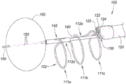
Fig. 2B is a perspective view depicting the distal end region 104 of the delivery device 103 with the various components deployed. In this embodiment, the anchor delivery member 150 includes an anchor 152 in the form of an inflatable member or balloon. Other embodiments of anchors 152 are described with reference to fig. 4A and 4G. The anchor 152 expands (or otherwise transitions) to a size that is greater than the size of the bladder neck such that the anchor 152 resists proximal retraction (e.g., relatively light tension). In embodiments where the anchor 152 is a balloon, the balloon may be elastic or inelastic, and may be inflated with an inflation medium (e.g., air or a liquid such as saline) introduced into the balloon 152 through one or more inflation ports 153. Here, three inflation ports 153 are located on the shaft of the anchor delivery member 150 and communicate with an inflation lumen that extends proximally back to the proximal control device 200, which may include ports for inflation with a syringe. Upon deployment of the anchor 152, the physician may proximally retract the delivery system 100 until the anchor 152 contacts the bladder neck and/or wall (if not already contacted).
The physician can use the imaging device of the outer shaft 120 to move the delivery device 103 proximally away from the anchor 152 until the physician is in the desired position within the urethra to begin deploying the implant 102. A retainer 142 on the distal control member 140 is releasably coupled with the distal engagement member 114 of the implant 102. The physician can position the retainer 142 in a position along the length of the urethra where the physician desires to deploy the distal end of the implant 102. This may involve moving the distal control member 140 and the inner shaft 130 together proximally and/or distally relative to the anchor delivery member 150. In another embodiment, the position of the retainer 142 is fixed relative to the anchor 152 such that the longitudinal position of the implant 102 within the anatomy is set by the system independent of any manipulation by the physician. The coupling of the distal engagement member 114 with the retainer 142 also allows the physician to manipulate the radial orientation of the implant 102 by rotating the distal control member 140 and the inner shaft 130 together. Active or passive shaping of distal control member 140 may allow for more desirable placement of implant 102. For example, member 140 may have a curvature that places the implant in a more anterior anatomical location. The curvature may be inherently set in the member 150 or actively applied by a physician through a separate entity such as a control wire. Once in the desired position and orientation, the physician can proximally retract the inner shaft 130 relative to the distal control member 140 to begin deploying the implant 102.
To assist in deployment, the inner shaft 130 can be rotated clockwise and counterclockwise (as depicted by arrow 134) about the distal control member 140. Referring back to fig. 1B-1C, implant 102 has a non-constant winding direction that, when considered to begin at distal engagement member 114, travels clockwise along annular structure 111a, then reverses direction along interconnect 112a to counter-clockwise for annular structure 111B, then reverses direction along interconnect 112B to clockwise for annular structure 111C, and then reverses direction along interconnect 112C to counter-clockwise for annular structure 111d until terminating at proximal engagement member 115. Depending on the direction of winding of the portion of the implant 102 that is about to exit the open distal end of the cavity 131, transition of the implant 102 toward the resting configuration may impart torque on the shaft 130 if the shaft 130 is not actively rotating when the implant 102 is deployed. This torque may cause the shaft 130 to passively rotate clockwise or counterclockwise, respectively (without user intervention). In certain embodiments described elsewhere herein, the shaft 130 actively rotates during deployment. Thus, rotation of the inner shaft 130 relative to the distal control member 140 allows the delivery device 103 to rotate and follow the winding direction of the implant 102. In some embodiments, all of the annular structures 111 are wound clockwise or counterclockwise in the same direction (e.g., as in the case of a fully helical or spiral implant), or do not have a set winding direction.
In this or other embodiments, the distal region of the inner shaft 130 is configured to be relatively more flexible than the more proximal portion of the inner shaft 130, which may allow for avoiding excessive movement of the remainder of the device 103 during deployment, resulting in better visualization and less tissue contact by the device 103. This configuration may also reduce the stress imparted on implant 102 by device 103 during delivery. For example, the portion of the inner shaft 130 that extends from the outer shaft 120 during deployment may be relatively more flexible than the portion of the inner shaft 130 that remains within the outer shaft 120, thus allowing the inner shaft 130 to bend more easily as the implant 102 exits the lumen 131. This in turn may stabilize the delivery device 103 and allow the physician to obtain a stable image of the appointment procedure.
Fig. 2B depicts implant 102 after three ring structures 111a, 111B, and 111c have been deployed. The shaft 130 continues to retract proximally until the entire implant 102, or at least all of the annular structures 111, have exited the cavity 131. If the physician is satisfied with the deployment position of the implant 102 and the deployment shape of the implant 102, the implant 102 may be released from the delivery device 103.
Release of the distal end of the implant 102 may be accomplished by releasing the retainer 142. The retainer 142 may be a cylindrical structure or other cannula that is actuated linearly or rotationally over a cavity or recess in which a portion of the implant 102 is received. In the embodiment of fig. 2B, the retainer 142 includes an opening or slot that allows the distal engagement member 114 to pass through. The retainer 142 may be rotated relative to the cavity or recess in which the distal engagement member 114 (not shown) is received until the opening or slot is positioned on the member 114, at which point the member 114 is free to release from the distal control member 130. Rotation of the retainer 142 may be accomplished by rotation of a rotatable shaft, rod, or other member coupled to the retainer 142 (and accessible at the proximal control 200).
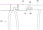
Fig. 2C and 2D are perspective views depicting another example embodiment of the system 100, in which different embodiments of the retainer 142 are shown in greater detail. Here, retainer 142 slides distally and/or proximally relative to distal control member 140. The distal engagement member 114 of the implant 102 may be received within a corresponding recess of the distal control member 140. The retainer 142 may slide over the distal engagement member 114 when received within the recess until the retainer 142 abuts the stepped portion of the member 140. The control wire 146 extends within the length of the control member 140 (either in the same lumen as the anchor delivery member 150 or in a different lumen). Control wire 146 is coupled to retainer 142 having an enlarged portion 147 from which control wire 146 may be routed through opening 148 into member 140.
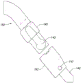
The engagement member 114 may be placed within the recess and the retainer 142 may be advanced over the engagement member 114 to secure the distal end of the implant 102 to the control member 140. When implant 102 is satisfactorily deployed within the urethra, such as in the state of fig. 2C, retainer 142 may be retracted proximally with control wire 146 to expose engagement member 114 and permit it to be released from member 140. Fig. 2E and 2F are perspective views depicting another embodiment of the system 100 having another configuration for the retainer 142 that operates in a similar manner as described with reference to fig. 2C and 2D. Here, the implant 102 is not shown, and the recess 143 in which the distal engagement member 114 may be received is shown in more detail.
Fig. 2G and 2H are side and perspective views, respectively, of another example embodiment of the system 100. In this embodiment, the inner shaft 130 includes a flexible distal extension 160 in which the lumen 131 (not shown) is located. In this configuration, the open distal end of lumen 131 is distal to the open distal end of lumen 132 (not shown), and distal control member 140 extends from the open distal end of lumen 132. Lumens 122, 123, and 124 (not shown) are located on outer shaft 120 opposite distal extension 160. The flexible distal extension 160 aids in flexibility for stabilizing the delivery system as well as stabilizing the image. The flexible extension 160 helps align the annular structure 111 in a planar fashion and helps guide (e.g., radially direct) the implant 102 toward the urethral wall during deployment.
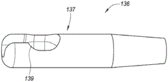
The release of the proximal end of the implant 102 is also controllable. Fig. 3A is a partial cross-sectional view depicting an example embodiment of the system 100, wherein a portion of the implant 102 is shown within the lumen 131 of the inner shaft 130. Here, the implant 102 is in a linear state prior to deployment, with the proximal engagement member 115 coupled with the grippers 136 that are slidable distally and/or proximally within the lumen 131. The grasper 136 may include a distal region 137 on the shaft 138 or coupled to the shaft 138. The grippers 136 are preferably controllable to rotate and longitudinally translate (e.g., push and pull) the implant 102 relative to the inner shaft 130.
Fig. 3B and 3C are perspective views depicting an example embodiment of distal end region 137 of gripper 136 without implant 102 and with implant 102, respectively. The grabber 136 includes a recess (also referred to as a cavity or pocket) 139 for receiving and retaining the proximal engagement member 115. Here, the enlarged portion 117 is held within the recess 139 by a distally necked region having a relatively small width. When within lumen 131, the side walls of inner shaft 130 retain proximal engagement member 115 within recess 139. When distal end region 137 exits lumen 131 (either by retracting inner shaft 130 relative to grabber 136 or by advancing grabber 136 relative to inner shaft 130), the constraint imparted by the inner shaft sidewall is no longer present and engagement member 115 is free to release from grabber 136. Thus, when the physician is satisfied with the placement of the deployed implant 102, the distal engagement member 114 can be released by moving the retainer 142 and allowing the distal engagement member 114 to disengage from the control member 140, and the proximal engagement member 115 can be released by exposing the grasper 136 from within the inner shaft 130 and allowing the proximal engagement member 115 to disengage from the grasper 136.
The gripper 136 may also assist in loading the implant 102. In some embodiments, applying a pulling force on the implant 102 with the grippers 136 (while the opposite end of the implant 102 is secured, such as by the retainers 142) facilitates the transition of the implant 102 from a resting configuration to a linear configuration suitable for insertion of the implant 102 into the inner shaft 130.
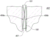
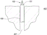
The anchor delivery member 150 can have a variety of different configurations and geometries (e.g., including configurations and geometries that extend across the bladder wall in one direction, that extend across the bladder wall in two directions (e.g., left and right), or that extend across the bladder wall in three directions). Fig. 4A-4B are cross-sectional views depicting an example embodiment of an anchor delivery member 150 in various stages of deployment within a patient. In fig. 4A, anchor delivery member 150 has been advanced through urethra 401 until open distal end 151 passes through the bladder neck and is within bladder 402, although in this and other embodiments, end 401 may be stopped prior to entering bladder 402. Here, two anchor arms 408a and 408b are received within the lumen of the anchor delivery member 150. In other embodiments, the anchor arms 408 may each be housed in a separate cavity within the member 150. The anchor arms 408 can be advanced distally relative to the anchor delivery member 150 (or the anchor delivery member 150 can be advanced into the bladder 402 and retracted proximally relative to the anchor arms 408) such that upon exiting the open distal end 151, deflectable portions 410a and 410B laterally transition into contact with the bladder wall to form the anchor 152 as depicted in fig. 4B.
The anchor arm 408 may be formed of a shape retaining material that is biased toward the resting configuration of fig. 4B. The distal ends of the anchor arms 408 may each have atraumatic tips (e.g., rounded, spherical, spheroidized) as depicted herein, or alternatively, the distal ends of the arms 408 may be bent away from the bladder wall to increase the atraumatic effect. In other embodiments, only one anchor arm 408 is used. Fig. 4C is a cross-sectional view depicting another example embodiment of an anchor delivery member 150. Here, deflectable portions 410a and 410b have a generally straight or linear shape and deflect from common shaft 412, and common shaft 412 may slide distally and/or proximally relative to anchor delivery member 150. In all of the anchoring embodiments described herein, one or more deflectable portions may deflect from a common shaft (such as depicted herein) or from a separate shaft (such as depicted in fig. 4A-4B).
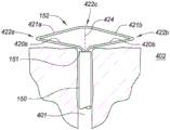
Fig. 4D-4E are partial cross-sectional views depicting another example embodiment of an anchor delivery member 150. Fig. 4D depicts an embodiment in which the anchor 152 is in a partially deployed state from the open distal end 151 of the anchor delivery member 150. Fig. 4E depicts the anchor 152 after full deployment within the bladder 402. Here, anchor 152 includes laterally deflectable struts 420a, 420b, 421a, and 421b connected by hinges 422a, 422b, and 422 c. Specifically, laterally deflectable posts 420a and 421a are connected by hinge 422a, laterally deflectable posts 420b and 421b are connected by hinge 422b, and posts 421a and 421b are connected by hinge 422 c. Again, the anchor 152 is biased toward the resting configuration depicted in fig. 4E and automatically transitions toward that configuration upon exposure from within the lumen of the anchor delivery member 150. The hinges 422 may each be implemented as living hinges (such as depicted in fig. 4E), e.g., defined by a reduced portion or a relatively more flexible section of the device. Other hinge configurations may also be utilized.
In another embodiment, a pull wire or other member 424 is attached to one or more of the struts 421 and/or hinges 422c and extends proximally to the proximal control device 200. In fig. 4E, the pulling member 424 is shown in phantom to indicate that it is optional. Proximal retraction of the pulling member 424 at the proximal control 200 causes the structural device to deflect laterally into the configuration depicted in fig. 4E. The device provides a significant locking force while maintaining tension on the pulling member 424.
Fig. 4F is a partial cross-sectional view depicting another example embodiment of an anchor delivery member 150. Here, the shape retaining element 430 has been advanced from within the lumen of the anchor delivery member 150 where the shape retaining element 430 is in a relatively straight or linear shape. Upon exiting the open distal end 151, the distal portion of the element 430 automatically transitions toward a laterally expanded shape 432, which in this embodiment is in the shape of a coil or spiral. Fig. 4G depicts another example embodiment in which the laterally expanded shape 432 has multiple loops and resembles the number "8" or bow tie. Many different shapes other than those depicted herein may be used for the laterally expanded shape 432. In all anchoring embodiments, the distal tip of the wire or element exposed to the body tissue may have a rounded or enlarged atraumatic end (as depicted in fig. 4F and 4G).
Upon completion of the implant deployment procedure, the anchors 152 may collapse or retract to allow removal of the delivery device 103. For example, in embodiments where the anchor 152 is a balloon, the balloon is deflated and optionally retracted into the lumen of the device 103, and then withdrawn from the bladder and urethra. In embodiments where the anchor 152 is a wire-type or other expandable member (such as the member described with reference to fig. 4A-4G), the anchor 152 is retracted into the lumen of the device 103 from which the anchor 152 is deployed, and the device 103 can then be withdrawn from the bladder and urethra. Retraction may be accomplished using fluid or pneumatic actuation, screw type mechanisms, or other means.
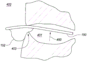
In fig. 2B, anchor 152 is a generally spherical balloon with anchor delivery member 150 extending through the center. In other embodiments, balloon anchor 152 may be laterally offset, or positioned on only one side of anchor delivery member 150. Fig. 4H is a partial cross-sectional view depicting an example embodiment of balloon 152 with lateral offset. Here, the laterally offset balloon 152 exerts a force on the side of the bladder neck 403 and in direction 450 against the anchor delivery member 150 (and delivery device 103).
In other embodiments, the device 103 may include two or more balloons that may be independently inflated in different lateral directions. Maintaining one or more remaining balloons in a deflated state while one or more balloons are inflated independently may allow a user to change the angle of the delivery catheter with respect to the anatomy and thus allow the implant to deploy in an anatomy with significant curvature. Fig. 4I depicts another example embodiment in which a first anchor balloon 152a is inflated to a larger size than a second anchor balloon 152b located on an opposite side of member 150. The member 150 is tilted away from the smaller balloon 152b in direction 451 due to the force exerted on the bladder wall. The selection of the appropriate balloon or balloons to inflate may be performed by the physician, and the inflation and deflation process may be repeated until the physician achieves the desired angular orientation of the device 103 within the anatomy, at which point the remainder of the delivery procedure may be performed. The delivery member 150 may be a flexible or rigid shaft that is preformed in a manner that will not interfere with the ability of the implant 102 to be placed in a desired anatomical location. For example, the curvature in the member 150 just proximal to the balloon-mounted location may allow the implant 102 to be placed further forward without binding from the bladder neck.
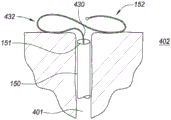
In some embodiments, the shaped balloon or substantially elastic balloon may be inflated at the same location as the bladder neck. Fig. 4J depicts an example embodiment of inflation of balloon 152 at bladder neck 403. Here, the balloon 152 includes a first flap 155 formed in the bladder 402 and a second flap 156 formed in the urethra 401. This configuration may be used to anchor the member 150 directly to the bladder neck 403.
Example embodiments of proximal control devices and related methods
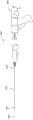
Fig. 5A is a side view depicting an example embodiment of delivery system 100 prior to deployment of implant 102, and fig. 5B is a side view depicting the embodiment, wherein implant 102 is in a deployed configuration (anchor delivery member 150 and distal control member 140 are not shown). In this embodiment, the proximal control 200 is a handheld device having a handle 201, a user actuator 202 (configured as a trigger in this example), and a body 203. The longitudinal axis of the delivery device 103 is indicated by dashed line 204. Proximal control device 200 may include a mechanism that is manually energized by actuation of actuator 202 to cause relative movement of the components of device 103. In other embodiments, the proximal control 200 may instead utilize an electric mechanism.
Fig. 6A is an interior view of the proximal control 200 depicting various mechanical components or sub-components within the main housing 203 of the control 200. In this embodiment, the proximal control 200 is configured to perform three types of motion on the implant 102, namely: advancing the implant 102 distally along the axis 204 (e.g., pushing), retracting the implant 102 and/or the inner shaft 130 proximally along the axis 204 (e.g., pulling), and rotating the inner shaft 130 about the axis 204 (e.g., rotating). In other embodiments, depending on the desired delivery function, the proximal control 200 may be configured to perform any subset of one or both of the above types of motions, to perform these types of motions but be imparted on different components or to perform other types of motions not mentioned herein.
In this embodiment, the proximal control 200 comprises a longitudinally translatable member 601, in this embodiment the longitudinally translatable member 601 is configured as a fork. The fork 601 is coupled to the trigger 202 such that depression of the trigger 202 causes the fork 601 to translate longitudinally proximally. The fork 601 is coupled with two proximally located ratchet members 602 and 603, which in this embodiment are configured as pawls. The pawl 602 has a set of teeth opposite the corresponding teeth on the pawl 603, and the teeth of each pawl 602 and 603 can interface or engage with complementary teeth on a gear 605 (see fig. 6B), the gear 605 being referred to herein as a pinion, which is part of the first gear assembly 600.
The switch 604 is accessible to a user and can be shifted between two positions, each of which is responsible for engaging only one of the pawls 602 and 603 with the pinion 605. Each of the pawls 602 and 603 is deflectable and biased toward engagement with the pinion 605 (e.g., with a spring). In this embodiment, placing the switch 604 in the downward position moves the pawl 602 out of engagement with the pinion 605 and moves the pawl 603 into engagement with the pinion 605. Proximal movement of the fork 601 and pawl 603 causes the pinion 605 to rotate counterclockwise. Placing the switch 604 in the up position reverses the engagement and engages the pawl 602 with the pinion 605, and the proximal movement of the fork 601 and pawl 602 causes the pinion 605 to rotate clockwise.
In this embodiment, the first gear assembly 600 includes a pinion gear 605, a second gear 610, a third gear 612, and a fourth gear 614. In other embodiments, the first gear assembly 600 may be implemented to achieve the same or similar functionality with more or fewer gears than those described herein.
Fig. 6B is a perspective view depicting the interior of this embodiment of the proximal control 200 in more detail. The proximally facing teeth on face gear 610 engage with the teeth on gear 612, gear 612 being referred to as the input gear. The teeth of input gear 612 engage the teeth of gear 614. Gear 614 is coupled to spool 616 or is integral with spool 616, spool 616 being configured to receive or retain gripper shaft 138. As can be seen in the embodiment of fig. 9A-9B, the spool 616 may include an optional groove or channel 617 in which the gripper shaft 138 may be received. Rotation of the spool 616 causes the gripper shaft 138 to wind onto the spool 616 or unwind from the spool 616 depending on the direction of rotation. The gripper shaft 138 is wound onto the reel 616 corresponding to proximal retraction of the implant 102 (e.g., into the inner lumen 131), while the gripper shaft 138 is unwound from the reel 616 corresponding to distal advancement of the implant 102 (e.g., out of the inner lumen 131). In the embodiment of fig. 9A-9B, the channel 617 is a spiral channel that extends multiple times around a circumferential portion of the spool 616. In the embodiment depicted in fig. 6B, the channel 617 is omitted.
In some embodiments, the input gear 612 may be configured as an intermittent gear in which one or more teeth are absent, such that rotation of the input gear 612 will not result in corresponding rotation of the other gear at all times. An example of such an input gear 612 is depicted in the perspective view of fig. 6C. From the perspective depicted herein, the input gear 612 has teeth 620 spaced at regular intervals on the left side 621 of the radial edge of the gear. In addition to the areas 623 where no teeth are present, teeth 620 are present at regular intervals on the right side 622 of the radial edge of the gear. There is a smooth surface hub 624 adjacent to the intermittent region 623. The right side 622 of the input gear 612 is configured to engage the spool gear 614. The placement of the intermittent region 623 is predetermined such that continued depression of the trigger 202 by the user (and thus continued rotation of the pinion 605, face gear 610, and input gear 612) is not translated into continued rotation of the spool gear 614. Instead, the spool gear 614 will only rotate when engaged with the portion of the input gear 612 having teeth 620, and will not rotate when the intermittent region 623 is traversing the spool gear 614. Placement of the intermittent regions 623 allows for suspension of longitudinal translation (e.g., distally and/or proximally) of the grasper shaft 138. In particular, the intermittent regions 623 are positioned such that longitudinal translation occurs only during certain portions of the delivery sequence.
In this embodiment, placing the switch 604 in the downward position translates the user's depression of the trigger 202 into a push on the implant 102, while placing the switch 604 in the upward position translates the user's depression of the trigger 202 into a pull on the implant 102 and/or the inner shaft 130. In other embodiments, the switch positions may be reversed to cause opposite movement.
Fig. 7A is a top down view depicting cam assembly 702 of proximal control 200. Cam assembly 702 includes an outer slotted tube or cam 703, an inner slotted tube 704, and a guide member 706. A cam assembly may be positioned within the fork 601. Fig. 7B is a perspective view depicting this embodiment of the cam 703. The cam 703 is coupled with the face gear 610 such that rotation of the face gear 610 also rotates the cam 703. The internally slotted tube 704 is mounted within the proximal control 200 such that it does not rotate as the cam 703 rotates. The guide member 706 may be configured as an arm or strut member that is located within and moves along both the slot 710 in the cam 703 and the slot 714 in the inner tube 704. The guide member 706 is coupled to a hub 802 (fig. 8) that is positioned within the inner slotted tube 704, which in turn is coupled to the inner shaft 130. Rotation of the face gear 610 causes rotation of the cam 703, which in turn causes the guide member 706 to move along the path or route of the slot 710 in the cam 703. Because the guide member 706 extends through the slot 714 in the non-rotatable inner tube 704, rotation of the cam 703 causes the guide member 706 to move only in the longitudinal direction and not in the radial direction.
The slot 710 may have one or more inclined slot portions and/or one or more radial slot portions. In the embodiment depicted herein, slot 710 has a plurality of sloped portions (e.g., slot portions 717a, 717b, and 717 c) and a plurality of radial portions (e.g., slot portions 719a, 719b, 719c, and 719 d). Other shapes may be used and associated together to form the desired path. The sloped slot portions 717 can have a constant or variable slope, and in some embodiments, the sloped slot portions can vary such that the slope is from positive to negative (e.g., "V").
The angled slot portion 717 may be an opening or slot in the cam 703 having a non-perpendicular and non-parallel angle (relative to the longitudinal axis 204) that moves the guide member 706 along the longitudinal axis 204 during rotation. In most embodiments, the radial slot portion 719 is parallel to the longitudinal axis 204, such that rotation of the cam 703 moves the radial slot portion 719 relative to the guide member 706, without the guide member 706 moving in the longitudinal direction (proximally or distally). The radial slot portion 719 may correspond to a pause in the delivery sequence in which the trigger 202 continues to be depressed and other components of the delivery device 103 are moving but the inner shaft 130 remains in the same relative position.
In fig. 7A, the guide member 706 is located at the distal-most end within the radial slot portion 719a (fig. 7B). To retract the inner shaft 130, the cam 703 is rotated in a counterclockwise direction 720. There is no longitudinal movement of the inner shaft 130 as the cam 703 rotates the radial slot portion 719a past the guide member 706. When the guide member 706 reaches the inclined groove portion 717a, it begins to retract proximally with the inner shaft 130. This process is repeated as the guide member 706 moves through the series of radial slot portions 719 (e.g., the shaft 130 is suspended from retracting) and angled slot portions 717 (e.g., the shaft 130 is retracted). In some embodiments, the guide member 706 may be selectively coupled with the outer shaft 120 to longitudinally move the component. For example, with the inner shaft 130 retracted proximally, the outer shaft 120 may also be retracted proximally, e.g., to allow the physician to continue imaging the deployment procedure. Similar embodiments utilizing cam assemblies that may be used with the embodiments described herein are described in incorporated international publication No. WO 2017/184887.
The three-phase delivery sequence may be described with respect to corresponding features of the implant 102. Each ring structure 111 and interconnect 112 is urged by gripper 136. In some embodiments, the implant 102 may also be rotated by the grippers 136. In some embodiments, the total longitudinal pushing distance traveled by the grippers 136 (provided by the spools 616) in implant delivery is roughly equivalent to the additive circumferential portion of all the annular structures 111 of the embodiment of the implant 102. The combined movement of pushing and rotating can ensure: although the lateral force impinges on the prostatic urethra, the annular structure 111 of the implant 102 is laid down in a plane to provide sufficient radial force to open the cavity. Each interconnect 112 of the implant 102 is subjected to a pull phase (not rotated) by the hub and cam. Thus, the total axial pull distance traveled by the hub inside the cam is roughly equivalent to the total longitudinal length of the implant 102. During the delivery sequence, the pull phase and the push/rotate phase do not occur simultaneously; they are mutually exclusive.
The proximal control 200 may be configured such that further deployment of the implant 102 is automatically prevented after all of the annular structures 111 have been deployed from the lumen 131 but before the proximal engagement feature 115 and recess 139 are advanced from within the lumen 131. This provides the physician with an opportunity to verify that the implant 102 has been properly deployed and placed prior to releasing the implant 102 from the delivery device 103.
Fig. 9A-9F are internal perspective views depicting an example embodiment of a proximal control 200 having a locking mechanism 900 for preventing premature release of the implant 102. The locking mechanism 900 interfaces with a groove or channel 902 in the proximally facing surface of the face gear 610, as shown in fig. 9A-9B. The longitudinally, laterally and radially inwardly movable tracking mechanism 904 has a head portion with a tab 905 and is biased distally such that the tab 905 is pressed into the channel 902 and tracks therein. As face gear 610 rotates via pinion gear 605 (not shown), tracking mechanism 904 moves along helical groove 902 and moves radially inward. This movement continues until the implant 102 is nearly fully deployed, but the proximal engagement member 115 is still held within the lumen 131 by the grippers 136. At this point, the tab 905 enters a relatively deep portion 906 of the channel 902 (e.g., cavity), the relatively deep portion 906 securely capturing the tracking mechanism 904. Further rotation of face gear 610 causes tracking mechanism 904 to move or rotate laterally in a semi-arc to the position depicted in fig. 9C-9D, wherein further lateral movement of arm 907 of tracking mechanism 904 is prevented by securing body 915. Further rotation of the face gear 610 is prevented, which in turn prevents rotation of all gears and prevents the user from continuing to pull the trigger 202.
If the physician is satisfied with the placement of the implant 102, the unlocking actuator or tab 910, which is accessible to the user, is pulled proximally outside the housing 203. The unlocking tab 910 is coupled directly or indirectly to the control line 146, the control line 146 being responsible for releasing the retainer 142 as described with reference to fig. 2C and 2D. Thus, proximal movement of the unlocking tab 910 causes the retainer 142 to move proximally and allows release of the distal engagement member 114 of the implant 102 from the delivery device 103. The unlocking tab 910 may also be coupled with the tracking mechanism 904 such that proximal retraction of the tab 910 withdraws the tab 905 from within the channel 902. This action unlocks the device 200 and the user is free to continue to press the trigger 202, which in turn advances the spool 616 forward to further unwind the grasper shaft 138 and cause the proximal engagement member 115 and the recess 139 of the implant 102 to exit the lumen 131 of the shaft 130. At this stage, both the distal engagement member 114 and the proximal engagement member 115 of the implant 102 are exposed, and the implant 102 is free to disengage or release from the device 103.
In some embodiments, distal control member 140 has a preset curvature (not shown) proximal to retainer 142. The distal control member 140 deforms from the preset curved shape (e.g., as depicted in fig. 2B, 2G, and 2H) when attached to the distal engagement member 114, and is therefore biased to return to the preset curved shape, which may also assist in the disengagement of the member 140 from the implant 102 (either in lieu of the device 200 rotating the member 140 or in addition to the device 200 rotating the member 140).
A stop surface 912 is present on the tracking mechanism 904 opposite another stop surface 914 on the stationary body 915. In the position of the tracking mechanism 904 shown in fig. 9B, these opposing stop surfaces 912 and 914 prevent proximal retraction of the unlocking tab 910 because the body 915 is a separate component that is held in a rest position (e.g., by the housing 203). The tracking mechanism 904 continues to move laterally (e.g., in the form of a semicircle) until the stop surface 912 stops and passes the stop surface 914, as shown in fig. 9D. This feature prevents premature unlocking of the implant 102 by proximally retracting the unlocking tab 910 before the implant 102 is fully deployed.
The proximal control 200 may also include an emergency release mechanism that allows for removal of the partially deployed implant 102 from the patient. The unlocking tab 910 may be disengaged from the tracking mechanism 904 by disengaging a notch of the deflectable arm 920 from a pawl 922 on the base of the tracking mechanism 904. In other embodiments, the notch and pawl features may be reversed. An emergency release button 924 having a ramped surface 925 is positioned below arm 920 (see fig. 9A-9B). Actuation, such as by pushing the release button 924, causes the ramp surface 925 to deflect the arm 920 upward and disengage the notch from the pawl 922, as depicted in fig. 9E. In this state, the unlocking tab 910 disengages from the tracking mechanism 904 and is free to retract proximally even when the stop surfaces 912 and 914 are in the relative position. Proximal retraction of the unlocking tab 910 retracts the control wire 146 and releases the distal engagement member 114 of the implant 102 from the distal control member 140. At this point, the partially deployed implant 102 remains attached to the grasper 136, and the grasper 136 may be retracted proximally into the outer shaft 120 and then completely removed from the patient.
Example embodiments of delivery methods
Fig. 10A is a flow chart depicting an example embodiment of a method 1000 of delivering an implant 102 using the system 100. The distal end region of the outer shaft 120 is inserted into the urethra, preferably with the inner shaft 130, distal control member 140, and anchor delivery member 150 in a retracted state fully contained within the outer shaft 120 such that no portion extends from the open distal tip of the outer shaft 120. After advancement into the urethra, at step 1002, anchor delivery member 150 is advanced distally relative to the remainder of delivery device 103 (e.g., members 120, 130, and 140) and used to deploy anchor 152 within the bladder. In some embodiments, deployment of the anchor 152 may be by introducing an inflation medium through an injection (e.g., luer taper) port to inflate one or more balloons (e.g., as depicted in fig. 2B and 4H-4J). Fig. 6A depicts a tube 650 for balloon inflation. In other embodiments, deployment of the anchors 152 can be advancement of one or more wire members from the anchor delivery member 150 such that they deflect into a position opposite the bladder wall (e.g., fig. 4A-4G). Longitudinal positioning (e.g., advancement and retraction) of the anchor delivery member 150 and/or any of the wireform members may be accomplished manually by a user manipulating the proximal end of the anchor delivery member 150 and/or any of the wireform members, either directly or with the proximal control device 200.
At step 1004, the anchor 152 can be held in tension against the bladder wall by applying a proximally directed force on the device 200. Thus, anchor 152 can provide system 100 with an ordinate upon which implant 102 can be deployed in a precise location. This feature may ensure that the implant is not placed too close to the bladder neck.
At 1006, if the distal control member 140 and the inner shaft 130 have not been advanced distally, the distal control member 140 and the inner shaft 130 can then be advanced distally from within the outer shaft 120 (e.g., step 1006 can occur prior to steps 1002 and/or 1004). The user can manipulate the position of the proximal control 200 by means of imaging (as described herein) until the implant 102 is in the desired position. Once the implant 102 is in the desired position, the implant deployment procedure may begin. The step for implant deployment may be performed automatically by a user actuating the proximal control 200 (e.g., actuating the trigger 202, selecting the position of the switch 604, etc.), or may be performed directly by manual manipulation of each component of the delivery device 103, or by a combination of both, as desired for a particular embodiment.
In some embodiments, deploying the implant 102 from within the lumen 131 is accomplished entirely by (1) advancing the grasper 136 distally relative to the inner shaft 130 without moving the inner shaft 130; in yet other embodiments, deploying the implant 102 from within the lumen 131 is accomplished entirely by (2) proximally retracting the inner shaft 130 relative to the grippers 136 without moving the grippers 136. In some embodiments, deployment of the implant 102 is accomplished entirely by (3) a combination of both movements. In still other embodiments, deployment of the implant 102 is fully achieved by (1), (2), or (3) in combination with one or more rotations of the inner shaft 130 in one or more directions (e.g., clockwise or counterclockwise) relative to the distal control member 140.
An example embodiment of a sequence of steps 1008, 1010, and 1012 for deploying the implant 102 is described with reference to fig. 10A and the timing diagram of fig. 10B. Referring first to fig. 10A, at step 1008, the first annular structure 111a is moved away from the lumen 131 of the inner shaft 130, at step 1010, the interconnect 112 is moved away from the lumen 131, and at step 1012, the second annular structure 111b is moved away from the lumen 131. Steps 1010 and 1012 may be repeated for each additional interconnect 112 and ring structure 111 present on implant 102.
In fig. 10B, step 1008 starts at T0 at the far left of the timing diagram. The deployment of the loop structure 111a corresponds to a duration labeled 1008, the deployment of the interconnect 123 corresponds to a time span 1010, and the deployment of the loop structure 111b corresponds to a time span 1012. Those of ordinary skill in the art will recognize that the difference between the deployment of the annular structure 111 and the deployment of the interconnect 112 is an approximation, as the transition between those portions of the implant 102 may be gradual and need not have precise demarcations.
The embodiment described with reference to fig. 10B is for an implant having a loop structure 111 with opposite winding directions (e.g., clockwise, then counter-clockwise, then clockwise, etc.). Three different movements are indicated in fig. 10B. At the top is rotational movement of the inner shaft 130 in one direction (e.g., clockwise), in the middle is longitudinal movement (e.g., proximal or distal) of one or more components of the delivery device 103, and at the bottom is rotational movement of the inner shaft 130 in the opposite direction (e.g., counterclockwise) from that indicated at the top. In embodiments where the annular structure 111 of the implant 102 is wound in all of the same direction, rotation of the inner shaft 130 will also be in only one direction.
From time T0 to T1, deployment of the implant 102 is achieved by rotating the inner shaft 130, as indicated in region 1031. At the same time, in region 1032, gripper 136, and thus implant 102, is advanced distally, while outer shaft 120 is neither longitudinally (neither distally nor proximally) nor rotationally moved, and inner shaft 130 is neither longitudinally moved (neither distally nor proximally). As an example, within the proximal control 200, a rotational movement of the inner shaft 130 is achieved by a user pressing the trigger 202 without a corresponding longitudinal movement of both the inner shaft 130 and the outer shaft 120, which is translated (by the fork and pawl) into a rotation of the pinion 605 and the face gear 610. Rotation of face gear 610 also rotates cam 703 of cam assembly 702 (fig. 7A-7B) while guide member 706 is in a radial slot portion (e.g., 719 a) and thus none of shafts 120 and 130 is longitudinally moved. Rotation of the cam 703 also causes the second gear assembly 800 (fig. 8) to rotate the inner shaft 130. Advancement of gripper 136 is caused by face gear 610 rotating input gear 612, which in turn rotates spool gear 614 (fig. 6A-6B) and causes spool 616 to rotate distally and unwind gripper shaft 138.
From time T1 to T2, the rotation of the inner shaft 130 stops, but the grasper 136 continues to advance distally while the shafts 120 and 130 are not longitudinally moved. As an example, within the proximal control 200, the user continues to press the trigger 202 and the cam 703 continues to rotate with the guide member 706 in the radial slot portion (e.g., 719 a). The cam 703 continues to rotate so that the ring gear 802 of the second gear assembly 800 rotates, but now an intermittent portion of the ring gear 802 (no teeth) is reached, none of the planet gears 810, 812 and 814 rotate, and thus the sun gear 816 and the inner shaft 130 cease to rotate. In this embodiment, deployment of the first annular structure 111a is completed at time T2.
From time T2 to T4, deployment of the first interconnect 112 occurs. In region 1033, from time T2 to T4, no distal advancement of the grasper 136 (and implant 102) occurs. Deployment of the interconnect 112 is accomplished by proximally retracting both the outer shaft 120 and the inner shaft 130 while maintaining the grippers 136 in place. This causes the interconnect 112 to exit the lumen 131 of the shaft 130. As an example, in the proximal control 200, the user continues to press the trigger 202 and the face gear 610 continues to rotate, as does both the cam 703 and the input gear 612. The intermittent portion 623 in the input gear 612 is reached and rotation of the input gear 612 no longer causes rotation of the spool gear 614 and thus the gripper shaft 138 stops advancing distally. Within cam assembly 702, guide member 706 transitions from a radial slot portion (e.g., 719 a) to an angled slot portion (e.g., 717 a), and rotation of cam 703 causes guide member 706 to move proximally. With the guide member 706 coupled with the shafts 120 and 130, these shafts 120 and 130 also move proximally.
Regarding the rotation of the inner shaft 130, from time T2 to T3, the rotation of the inner shaft 130 does not occur. Within proximal control 200, the intermittent portion of ring gear 802 continues and shaft 130 does not rotate through sun gear 816.
In embodiments where the interconnect 112 is straight, it may be desirable to avoid rotating the shaft 130 as the interconnect 112 expands from time T2 to T4. For embodiments where the interconnect 112 is curved (such as the embodiments of fig. 1B-1D), it may be desirable to begin rotation of the inner shaft 130 during deployment of the interconnect. Fig. 10B depicts deployment of the interconnect 112 for bending and rotation of the inner shaft 130 in the opposite direction from T3 to T4, as indicated by region 1034. As an example, within proximal control 200, the user continues to press trigger 202 and this movement is translated to ring gear 802, ring gear 802 having an area with teeth that engage with planetary gears responsible for movement of sun gear 816 in the opposite direction. Thus, the sun gear 816 begins to rotate in the opposite direction and the inner shaft 130 likewise rotates in the opposite direction to the direction of times T0 to T1, which facilitates deployment of the interconnect 112 and causes the inner shaft to begin rotating in a direction suitable for the oppositely wound second annular structure 111 b.
At T4, the interconnect 112 completes deployment and the second annular structure 111b begins deployment. The shafts 120 and 130 cease to retract proximally as indicated by the discontinuation of region 1033. At T4, the grasper shaft 138 resumes distal advancement in region 1035 without the outer shaft 120 moving neither rotationally nor longitudinally. The inner shaft 130 continues to rotate, as indicated in region 1034, but the inner shaft 130 does not move longitudinally. As an example, within the proximal control 200, the user continues to press the trigger 202. Cam 703 continues to rotate, but guide member 706 reaches the second radial slot portion (e.g., 719 b) and guide member 706 stops moving proximally (as does shafts 120 and 130). Sun gear 816 continues to rotate. Intermittent portion 623 of input gear 612 stops and teeth 620 reengage spool gear 614, causing both spool gear 614 and spool 616 to begin rotating again, and thus gripper shaft 138 to also begin advancing distally.
These movements continue until time T5, at which time the inner shaft 130 stops rotating. Within proximal control 200, an intermittent portion of ring gear 802 is reached, and gear 802 is disengaged from the planetary gears, and sun gear 816 stops rotating. The user continues to press trigger 202 from time T5 to T6 and the component operates with a similar motion as from time T1 to T2 as described. If another interconnect 112 and ring structure 111 are present, the sequence starting at time T6 may be the same as the described sequence starting at time T2 and continuing to time T6. This process may be repeated as necessary until all of the annular structures 111 of the implant 102 are deployed. In some embodiments, further depression of trigger 202 may be stopped by locking mechanism 900 (fig. 9A-9B) to prevent premature deployment and release of proximal engagement portion 115.
In many of the embodiments described herein, deployment of all of the ring structures 111 may occur through a single continuous press of the trigger 202. In all of these embodiments, the proximal control 200 may instead be configured such that repeated pulling of the trigger 202 is required to deploy all of the annular structures 111 of the implant 102.
During deployment, e.g., after time T0 until deployment of the proximal-most loop structure 112 is completed, if the physician wishes to recapture the implant 102, pressing the trigger 202 may be stopped. The trigger 202 may be spring loaded or otherwise biased to return to the outermost position. The physician may adjust the switch 604 from a position corresponding to deployment to a different position corresponding to recapture. This adjustment of switch 604 will disengage pawl 603 and engage pawl 602. The physician may again depress trigger 202 and this depression will translate into a reverse motion of face gear 610, which in turn translates into a reverse motion of the rest of first gear assembly 600, cam 703 and second gear assembly 800. For example, if switch 604 is adjusted at any time between times T0 and T6, the next depression of trigger 202 will cause the sequence of events to reverse from right to left in FIG. 10B. Since these movements are merely inversions of the movements already described, they will not be repeated here.
If the physician is satisfied with the deployment, at 1014, the distal and proximal engaging portions 114, 115 of the implant 102 may be released from the distal control member 140 and the grasper 136, respectively. As an example, in the proximal control 200, the physician may pull on the tab 910 to allow the trigger 202 to be depressed in the remainder, which in turn may deploy the proximal engagement portion 115 of the implant 102 by distal advancement of the grasper 136, proximal retraction of the shafts 120 and 130, or both. The tab 910 may be coupled with the control wire 146, and pulling on the tab 910 may pull the wire 146 and remove the retainer 142 from the distal engagement portion 114.
The anchor 152 can then be recaptured (e.g., deflation of the balloon or retraction of the wire member), and if desired, can be withdrawn into the anchor delivery member 150. The anchor delivery member 150, distal control member 140, and inner shaft 130 can be retracted into the outer shaft 120 and then withdrawn from the urethra.
The embodiments described herein are re-stated and elaborated in the following paragraphs without explicit reference to the drawings. In many example embodiments, a system for delivering an implantable device is provided, wherein the system includes a delivery device comprising: an outer tubular member; an inner tubular member having a first lumen and a second lumen, the inner tubular member being slidable within the outer tubular member, wherein the first lumen is adapted to receive an elongate grasper member configured to releasably couple with a proximal portion of an implant; and a distal control member slidable within the second lumen, wherein the distal control member includes a retainer configured to releasably couple with the distal portion of the implant.
In some embodiments, the implant is configured to maintain the prostatic urethra in an at least partially open state. In some embodiments, the implant has: a body comprising first and second annular structures; and an interconnect extending between the first and second annular structures. The body of the implant may be just a single wire. The implant may include: a distal engagement member configured to releasably couple with the retainer; and/or a proximal engagement member configured to releasably couple with the elongate grasper member. In some embodiments, the implant comprises: a linear distal engagement member extending proximally away from a distal-most portion of the implant; and/or a linear proximal engagement member. In some embodiments, the first annular structure may be the distal-most annular structure of the implant and have a relatively smaller width than the second annular structure.
In some embodiments, the inner tubular member may be slid and rotated relative to the distal control member while the retainer is releasably coupled with the distal portion of the implant. The system may also include an elongate member coupled with the holder and having a proximal end that is manipulable by a user to permit release of the distal portion of the implant from the holder. In some embodiments, the retainer is tubular and is adapted to slide along the distal control member. The distal control member may comprise a recess adapted to receive the distal portion of the implant, and the retainer may be movable to expose the recess when the distal portion of the implant is received within the recess. In some embodiments, the retainer includes a slot through which the implant can pass.
In some embodiments, the system includes an elongate anchor member. The elongate anchor member can include an anchor configured to contact the bladder wall. The anchor may be an inflatable balloon or a plurality of inflatable balloons. In some embodiments, the elongate anchor member comprises a wire-shaped member having a portion configured to automatically deflect upon deployment.
In some embodiments, the elongate grasper member includes a recess configured to releasably couple with the proximal portion of the implant. In some embodiments, the system is configured such that the proximal portion of the implant is free to release from the recess of the elongate grasper member when the recess is not bound by the first lumen.
In some embodiments, a proximal control is included and coupled to the proximal end region of the delivery device. The proximal control may be manipulated by a user to control deployment of the implant from the delivery device. In some embodiments, the proximal control comprises a housing and is configured to advance the elongate grasper member distally relative to the housing and the inner tubular member, and/or to retract and rotate the inner tubular member proximally relative to the housing and the distal control member, and/or to retract the outer tubular member proximally relative to the housing.
In some embodiments, the proximal control device comprises: a user actuator; a first gear assembly coupled with the user actuator; a cam assembly coupled with the first gear assembly; and a second gear assembly coupled with the cam assembly. In some embodiments, the first gear assembly is configured to control longitudinal movement of the elongate gripper member, the cam assembly is configured to control longitudinal movement of the inner tubular member, and/or the second gear assembly is configured to control rotation of the inner tubular member.
In many embodiments, a system for delivering an implantable device is provided, wherein the system comprises: a delivery device, the delivery device comprising: a first elongate member having a lumen; an elongate grasper member slidable within the lumen and configured to retain a proximal portion of the implant; and a distal control member configured to hold a distal portion of the implant; and a proximal control coupled to the proximal end region of the delivery device, the proximal control comprising a user actuator and a housing.
In some embodiments, the proximal control comprises a first gear assembly within the housing, the proximal control configured to translate movement of the user actuator into movement in the first gear assembly. In some embodiments, the proximal control includes a switch that selects between movement of the first gear assembly in the first direction and movement of the first gear assembly in the second direction. In some embodiments, the user actuator is coupled to a fork that is coupled to the first pawl and the second pawl. The switch selectively may engage either the first pawl or the second pawl with the pinion. The proximal control may be configured such that rotation of the pinion gear results in rotation of the face gear. The proximal control may be configured such that rotation of the face gear results in rotation of a spool coupled with the elongate gripper member.
In some embodiments, the system further comprises: an input gear engaged with the face gear; and a spool gear engaged with the input gear, the spool gear being coupled to or integrated with the spool. In some embodiments, the input gear is a discontinuous gear and rotation of the spool gear by the input gear results in rotation of the spool and longitudinal movement of the elongate gripper member. In some embodiments, movement of the first gear assembly in the first direction causes distal movement of the elongate gripper member, and movement of the first gear assembly in the second direction causes proximal movement of the elongate gripper member.
In some embodiments, the proximal control comprises a cam assembly within the housing, the proximal control configured to translate movement of the user actuator into movement in the cam assembly. The cam assembly may be coupled with the first elongate member and may be configured to move the first elongate member proximally relative to the housing. In some embodiments, the cam assembly includes a rotatable cam having a slot, the first elongate member being coupled with a guide member received within the slot. In some embodiments, the slot includes an angled slot portion and a radial slot portion. The cam assembly may include an inner tube having a longitudinal slot in which the guide member is received.
In some embodiments, the first gear assembly includes a face gear having a first set of teeth that engage with teeth of another gear in the first gear assembly, wherein the face gear is coupled with the cam assembly such that movement of the face gear results in movement in the cam assembly.
In some embodiments, the proximal control comprises a second gear assembly, and movement in the cam assembly may result in movement in the second gear assembly. The second gear assembly may be coupled with the first elongated member and may be configured to rotate the first elongated member relative to the housing. The second gear assembly may include a sun gear having an aperture configured to receive the first elongated member such that rotation of the sun gear results in rotation of the first elongated member. In some embodiments, the second gear assembly includes a ring gear coupled with the cam assembly and with the sun gear via the planetary gear assembly. The ring gear may engage the planetary gear assembly such that rotation of the ring gear in a first direction causes rotation of the sun gear in a first direction and rotation of the ring gear in a second direction causes rotation of the sun gear in a second direction, the first direction rotation of the sun gear being opposite the second direction rotation.
In some embodiments, the proximal control device includes a releasable locking mechanism that prevents a proximal portion of the implant held by the elongate grasper member from exiting the lumen. In some embodiments, the locking mechanism includes a movable tracking mechanism that interfaces with a groove in the face gear of the first gear assembly, the proximal control configured such that movement of the face gear moves the tracking mechanism as the implant exits the lumen. The proximal control may be configured such that the tracking mechanism is prevented from further movement until the proximal portion of the implant exits the lumen.
In some embodiments, the proximal control comprises a release structure configured to be actuated by a user, wherein the release structure is configured to disengage the tracking mechanism from the face gear to allow the proximal portion of the implant to exit the lumen. The release structure may be a pull tab and may be coupled with the elongate gripper member.
In many embodiments, a method of delivering an implant is provided, the method comprising: advancing a delivery device within a body lumen of a patient, wherein the delivery device comprises: a first tubular member housing an implant; a distal control member slidable within the first tubular member and releasably coupled with the distal portion of the implant; and an elongate grasper member slidable within the first tubular member and releasably coupled with the proximal portion of the implant; causing relative movement between the elongate grasper member and the first tubular member to expose at least a portion of the implant from within the first tubular member; and releasing the distal portion of the implant from the distal control member and the proximal portion of the implant from the elongate grasper member.
In some embodiments, the body cavity is the prostatic urethra of a human. In some embodiments, upon release of the distal and proximal portions, the implant is released from the delivery device in a state adapted to maintain the prostatic urethra in at least a partially open state.
In some embodiments, the implant has: a body comprising first and second annular structures; and an interconnect extending between the first and second loop structures and causing relative movement may include distally advancing the elongate gripper member. In some embodiments, the method further comprises: during exposure of the first annular structure from the first tubular member, the first tubular member is rotated in a first direction relative to the distal control member. In some embodiments, the method further comprises: during exposure of the second annular structure from the first tubular member, the first tubular member is rotated relative to the distal control member in a second direction, the second direction being opposite the first direction. Rotation of the first tubular member in the first and second directions may occur when the distal control member is releasably coupled with the distal portion of the implant.
In some embodiments, the method further comprises: the first tubular member is proximally retracted relative to the elongate grasper member and the distal control member to expose the interconnect from the first tubular member. In some embodiments, the method further comprises: the first tubular member is rotated as it is retracted proximally. In these embodiments, the interconnect may be curved.
In some embodiments, the retainer couples the distal portion of the implant to the distal control member, and the method includes: the retainer is released to release the distal portion of the implant from the distal control member.
In some embodiments, the method further comprises: a proximal portion of the implant is exposed from within the first tubular member to release the proximal portion of the implant from the elongate grasper member.
In some embodiments, the method further comprises: the delivery device is anchored against the wall of the bladder prior to causing relative movement between the elongate grasper member and the first tubular member. In some embodiments, anchoring the delivery device includes inflating a balloon in the bladder.
In some embodiments, the proximal control device is coupled to the proximal end region of the delivery device, and the method comprises: the user actuator of the proximal control is moved by the user, wherein moving the user actuator results in a movement in the first gear assembly of the proximal control. In some embodiments, the first gear assembly causes distal advancement of the elongate gripper member relative to the first tubular member. In some embodiments, the first gear assembly causes movement in the cam assembly and the second gear assembly. In some embodiments, movement in the cam assembly causes intermittent retraction of the first tubular member relative to the distal control member. In some embodiments, movement in the second gear assembly results in intermittent rotation of the first tubular member relative to the distal control member.
In some embodiments, the user actuator is a first user actuator, and the method includes: a second user actuator of the proximal control is actuated. In some embodiments, actuating the second user actuator unlocks the locking mechanism and allows release of the distal portion of the implant from the distal control member and release of the proximal portion of the implant from the elongate grasper member. In some embodiments, actuating the second user actuator removes the retainer from the distal portion of the implant and rotates the distal control member to cause the distal portion of the implant to disengage from the distal control member.
In some embodiments, the first tubular member is an inner tubular member slidably received within an outer tubular member of the delivery device.
All features, elements, components, functions, and steps described with reference to any embodiment provided herein are intended to be freely combinable and replaceable with features, elements, components, functions, and steps from any other embodiment. If a feature, element, component, function, or step is described with reference to only one embodiment, it should be understood that the feature, element, component, function, or step can be used with every other embodiment described herein unless expressly stated otherwise. Thus, this section is used at any time as a basis for and in written support for introducing claims which combine features, elements, components, functions, and steps from different embodiments or replace features, elements, components, functions, and steps from one embodiment with features, elements, components, and steps from another embodiment, even though the following description does not explicitly state such a combination or substitution in a particular instance. It is expressly recognized that each and every possible combination and substitution is expressly stated to be overly burdensome, especially given that one of ordinary skill in the art will readily recognize the permissibility of each and every such combination and substitution.
As used herein and in the appended claims, the singular forms "a," "an," and "the" include plural referents unless the context clearly dictates otherwise.
While the embodiments are susceptible to various modifications and alternative forms, specific examples thereof have been shown in the drawings and are herein described in detail. It should be understood, however, that the embodiments are not to be limited to the particular forms disclosed, but to the contrary, the embodiments are to cover all modifications, equivalents, and alternatives falling within the spirit of the disclosure. Furthermore, any features, functions, steps or elements of the embodiments may be recited in or added to the claims, as well as negative limitations that define the inventive scope of the claims by features, functions, steps or elements that are not within that scope.
Claims (30)
1. A system for delivering an implantable device, the system comprising a delivery device comprising:
an outer tubular member;
an inner tubular member having a first lumen and a second lumen, the inner tubular member being slidable within the outer tubular member, wherein the first lumen is adapted to receive an elongate grasper member configured to releasably couple with a proximal portion of an implant; and
A distal control member slidable within the second lumen, wherein the distal control member comprises a retainer configured to releasably couple with a distal portion of the implant,
wherein the implant is deformable into a linear configuration when in the first lumen of the inner tubular member.
2. The system of claim 1, further comprising the implant.
3. The system of claim 2, wherein the implant is configured to maintain the prostatic urethra in an at least partially open state.
4. A system according to claim 3, wherein the implant has: a body comprising first and second annular structures; and an interconnect extending between the first and second annular structures.
5. The system of claim 4, wherein the body of the implant is only a single wire.
6. The system of claim 2, wherein the implant comprises a distal engagement member configured to releasably couple with the retainer.
7. The system of claim 2, wherein the implant comprises a proximal engagement member configured to releasably couple with the elongate grasper member.
8. The system of claim 2, wherein the implant includes a linear distal engagement member extending proximally away from a distal-most portion of the implant.
9. The system of claim 2, wherein the implant comprises a linear proximal engagement member.
10. The system of claim 4, wherein the first annular structure is a distal-most annular structure of the implant and has a relatively smaller width than the second annular structure.
11. The system of claim 1, wherein the inner tubular member is slidable and rotatable relative to the distal control member while the retainer is releasably coupled with the distal portion of the implant.
12. The system of claim 11, further comprising an elongate member coupled with the retainer and having a proximal end manipulable by a user to permit release of the distal portion of the implant from the retainer.
13. The system of claim 12, wherein the retainer is tubular and is adapted to slide along the distal control member.
14. The system of claim 1, wherein the distal control member comprises a recess adapted to receive the distal portion of the implant.
15. The system of claim 14, wherein the retainer is movable to expose the recess when the distal portion of the implant is received within the recess.
16. The system of claim 15, wherein the retainer comprises a slot.
17. The system of claim 1, further comprising an elongated anchor member.
18. The system of claim 17, wherein the elongate anchor member comprises an anchor configured to contact a bladder wall.
19. The system of claim 18, wherein the anchor is an inflatable balloon.
20. The system of claim 18, wherein the elongate anchoring member comprises a plurality of balloons.
21. The system of claim 17, wherein the elongated anchor member comprises a wire-shaped member having a portion configured to automatically deflect upon deployment.
22. The system of claim 1, wherein the elongate gripper member comprises a recess configured to releasably couple with the proximal portion of an implant.
23. The system of claim 22, wherein the system is configured such that the proximal portion of the implant is free to release from the recess of the elongate grasper member when the recess is not bound by the first lumen.
24. The system of claim 1, further comprising a proximal control coupled with a proximal region of the delivery device.
25. The system of claim 24, wherein the proximal control is manipulable by a user to control deployment of the implant from the delivery device.
26. The system of claim 24, wherein the proximal control comprises a housing and is configured to advance the elongate grasper member distally relative to the housing and the inner tubular member.
27. The system of claim 24, wherein the proximal control comprises a housing and is configured to retract and rotate the inner tubular member proximally relative to the housing and the distal control member.
28. The system of claim 24, wherein the proximal control comprises a housing and is configured to retract the outer tubular member proximally relative to the housing.
29. The system of claim 24, wherein the proximal control comprises:
a user actuator;
a first gear assembly coupled with the user actuator;
a cam assembly coupled with the first gear assembly; and
a second gear assembly is coupled with the cam assembly.
30. The system of claim 29, wherein the first gear assembly is configured to control longitudinal movement of the elongated gripper member, the cam assembly is configured to control longitudinal movement of the inner tubular member, and the second gear assembly is configured to control rotation of the inner tubular member.
Applications Claiming Priority (3)
| Application Number | Priority Date | Filing Date | Title |
|---|---|---|---|
| US201662432542P | 2016-12-09 | 2016-12-09 | |
| US62/432542 | 2016-12-09 | ||
| PCT/US2017/065469 WO2018107123A1 (en) | 2016-12-09 | 2017-12-08 | Systems, devices, and methods for the accurate deployment of an implant in the prostatic urethra |
Publications (2)
| Publication Number | Publication Date |
|---|---|
| CN110267627A CN110267627A (en) | 2019-09-20 |
| CN110267627B true CN110267627B (en) | 2023-07-11 |
Family
ID=62491374
Family Applications (1)
| Application Number | Title | Priority Date | Filing Date |
|---|---|---|---|
| CN201780086171.2A Active CN110267627B (en) | 2016-12-09 | 2017-12-08 | Systems, devices, and methods for accurately deploying implants in the prostatic urethra |
Country Status (7)
| Country | Link |
|---|---|
| US (3) | US11096774B2 (en) |
| EP (1) | EP3551140A4 (en) |
| JP (3) | JP7091335B2 (en) |
| CN (1) | CN110267627B (en) |
| AU (2) | AU2017371223B2 (en) |
| CA (1) | CA3046087A1 (en) |
| WO (1) | WO2018107123A1 (en) |
Families Citing this family (13)
| Publication number | Priority date | Publication date | Assignee | Title |
|---|---|---|---|---|
| AU2017254659B2 (en) | 2016-04-21 | 2022-10-06 | Zenflow, Inc. | Systems and methods for implants and deployment devices |
| WO2017192145A1 (en) * | 2016-05-06 | 2017-11-09 | University Hospitals Health Systems, Inc. | Ureteral stent |
| JP7091335B2 (en) | 2016-12-09 | 2022-06-27 | ゼンフロー, インコーポレイテッド | Systems, devices, and methods for the accurate deployment of implants within the urethral prostate |
| JP2020528790A (en) * | 2017-07-28 | 2020-10-01 | ゼンフロー, インコーポレイテッド | Systems, devices, and methods for dilating the diameter of the prostatic urethra |
| US20210022594A1 (en) * | 2018-05-04 | 2021-01-28 | Prodeon, Inc. | Delivery systems and devices for the treatment of benign prostatic hyperplasia and related lower urinary tract symptoms |
| CA3100240A1 (en) | 2018-05-17 | 2019-11-21 | Zenflow, Inc. | Systems, devices, and methods for the accurate deployment and imaging of an implant in the prostatic urethra |
| US10441449B1 (en) | 2018-05-30 | 2019-10-15 | Vesper Medical, Inc. | Rotary handle stent delivery system and method |
| US10449073B1 (en) | 2018-09-18 | 2019-10-22 | Vesper Medical, Inc. | Rotary handle stent delivery system and method |
| CN110584853B (en) * | 2019-11-13 | 2020-02-07 | 微创优通医疗科技(上海)有限公司 | Operating system, implant delivery system and delivery method |
| AU2020387396A1 (en) * | 2019-11-19 | 2022-04-21 | Zenflow, Inc. | Systems, devices, and methods for the accurate deployment and imaging of an implant in the prostatic urethra |
| US11219541B2 (en) | 2020-05-21 | 2022-01-11 | Vesper Medical, Inc. | Wheel lock for thumbwheel actuated device |
| WO2022076646A1 (en) * | 2020-10-08 | 2022-04-14 | Zenflow, Inc. | Systems, devices, and methods for the retrieval of an implant in the prostatic urethra |
| WO2023183238A1 (en) * | 2022-03-23 | 2023-09-28 | Teleflex Life Sciences Limited | Tissue manipulating systems and methods of use |
Citations (1)
| Publication number | Priority date | Publication date | Assignee | Title |
|---|---|---|---|---|
| WO2005016185A1 (en) * | 2003-08-14 | 2005-02-24 | Strecker Ernst P | Convoluted stent |
Family Cites Families (451)
| Publication number | Priority date | Publication date | Assignee | Title |
|---|---|---|---|---|
| US3657744A (en) | 1970-05-08 | 1972-04-25 | Univ Minnesota | Method for fixing prosthetic implants in a living body |
| US5190546A (en) | 1983-10-14 | 1993-03-02 | Raychem Corporation | Medical devices incorporating SIM alloy elements |
| US5041126A (en) | 1987-03-13 | 1991-08-20 | Cook Incorporated | Endovascular stent and delivery system |
| US4813925A (en) | 1987-04-21 | 1989-03-21 | Medical Engineering Corporation | Spiral ureteral stent |
| US5634946A (en) | 1988-08-24 | 1997-06-03 | Focal, Inc. | Polymeric endoluminal paving process |
| US5413601A (en) | 1990-03-26 | 1995-05-09 | Keshelava; Viktor V. | Tubular organ prosthesis |
| IL94138A (en) | 1990-04-19 | 1997-03-18 | Instent Inc | Device for the treatment of constricted fluid conducting ducts |
| US5160341A (en) * | 1990-11-08 | 1992-11-03 | Advanced Surgical Intervention, Inc. | Resorbable urethral stent and apparatus for its insertion |
| US5269802A (en) | 1991-09-10 | 1993-12-14 | Garber Bruce B | Prostatic stent |
| US5662713A (en) | 1991-10-09 | 1997-09-02 | Boston Scientific Corporation | Medical stents for body lumens exhibiting peristaltic motion |
| US5876445A (en) | 1991-10-09 | 1999-03-02 | Boston Scientific Corporation | Medical stents for body lumens exhibiting peristaltic motion |
| EP0536610B1 (en) | 1991-10-11 | 1997-09-03 | Angiomed GmbH & Co. Medizintechnik KG | Stenosis dilatation device |
| US5354309A (en) | 1991-10-11 | 1994-10-11 | Angiomed Ag | Apparatus for widening a stenosis in a body cavity |
| US5372600A (en) | 1991-10-31 | 1994-12-13 | Instent Inc. | Stent delivery systems |
| US5261916A (en) * | 1991-12-12 | 1993-11-16 | Target Therapeutics | Detachable pusher-vasoocclusive coil assembly with interlocking ball and keyway coupling |
| US5507767A (en) | 1992-01-15 | 1996-04-16 | Cook Incorporated | Spiral stent |
| US5772668A (en) * | 1992-06-18 | 1998-06-30 | American Biomed, Inc. | Apparatus for placing an endoprosthesis |
| US5342387A (en) | 1992-06-18 | 1994-08-30 | American Biomed, Inc. | Artificial support for a blood vessel |
| DE4236571A1 (en) | 1992-10-29 | 1994-05-05 | Hans Prof Dr Med Sachse | Tubular ureteral splint |
| DE69434453T2 (en) | 1993-03-11 | 2006-03-16 | Medinol Ltd. | stent |
| AU6495794A (en) | 1993-03-30 | 1994-10-24 | Instent Inc. | Temporary stent system |
| US6090115A (en) | 1995-06-07 | 2000-07-18 | Intratherapeutics, Inc. | Temporary stent system |
| SE505436C2 (en) | 1993-04-27 | 1997-08-25 | Ams Medinvent Sa | prostatic stent |
| IL105828A (en) | 1993-05-28 | 1999-06-20 | Medinol Ltd | Medical stent |
| FR2706764B1 (en) | 1993-06-24 | 1995-08-04 | Synthelabo | |
| US5476505A (en) * | 1993-11-18 | 1995-12-19 | Advanced Cardiovascular Systems, Inc. | Coiled stent and delivery system |
| US5490860A (en) | 1993-12-08 | 1996-02-13 | Sofamor Danek Properties, Inc. | Portable power cutting tool |
| EP0666065A1 (en) | 1994-02-02 | 1995-08-09 | Katsushi Mori | Stent for biliary, urinary or vascular system |
| IL108832A (en) | 1994-03-03 | 1999-12-31 | Medinol Ltd | Urological stent and deployment device therefor |
| US5556413A (en) | 1994-03-11 | 1996-09-17 | Advanced Cardiovascular Systems, Inc. | Coiled stent with locking ends |
| US5554181A (en) | 1994-05-04 | 1996-09-10 | Regents Of The University Of Minnesota | Stent |
| US5540701A (en) | 1994-05-20 | 1996-07-30 | Hugh Sharkey | Passive fixation anastomosis method and device |
| DE69528216T2 (en) | 1994-06-17 | 2003-04-17 | Terumo Corp | Process for the production of a permanent stent |
| US5857998A (en) * | 1994-06-30 | 1999-01-12 | Boston Scientific Corporation | Stent and therapeutic delivery system |
| US5545210A (en) | 1994-09-22 | 1996-08-13 | Advanced Coronary Technology, Inc. | Method of implanting a permanent shape memory alloy stent |
| JP2589056B2 (en) | 1994-10-11 | 1997-03-12 | アステムテック株式会社 | Prostascope with bridge |
| AU700717B2 (en) | 1994-10-20 | 1999-01-14 | Intra Therapeutics, Inc. | Cystoscope delivery system |
| US7001328B1 (en) | 1994-11-15 | 2006-02-21 | Kenton W. Gregory | Method for using tropoelastin and for producing tropoelastin biomaterials |
| US5514176A (en) | 1995-01-20 | 1996-05-07 | Vance Products Inc. | Pull apart coil stent |
| AU719980B2 (en) | 1995-02-22 | 2000-05-18 | Menlo Care, Inc. | Covered expanding mesh stent |
| EP0812165A4 (en) | 1995-02-27 | 2000-01-19 | Instent Inc | Hollow stent |
| US5556414A (en) | 1995-03-08 | 1996-09-17 | Wayne State University | Composite intraluminal graft |
| US6053943A (en) | 1995-12-08 | 2000-04-25 | Impra, Inc. | Endoluminal graft with integral structural support and method for making same |
| US5738654A (en) | 1995-03-20 | 1998-04-14 | Contimed, Inc. | Self cleansing bladder drainage device |
| US5681274A (en) | 1995-03-31 | 1997-10-28 | Boston Scientific Corporation | Variable length uretheral stent |
| DE29507519U1 (en) | 1995-05-05 | 1995-08-10 | Angiomed Ag | Endosphincter and set for releasable closing of the urethra |
| US6602281B1 (en) | 1995-06-05 | 2003-08-05 | Avantec Vascular Corporation | Radially expansible vessel scaffold having beams and expansion joints |
| US5603722A (en) | 1995-06-06 | 1997-02-18 | Quanam Medical Corporation | Intravascular stent |
| US5674242A (en) | 1995-06-06 | 1997-10-07 | Quanam Medical Corporation | Endoprosthetic device with therapeutic compound |
| US7611533B2 (en) | 1995-06-07 | 2009-11-03 | Cook Incorporated | Coated implantable medical device |
| US7867275B2 (en) | 1995-06-07 | 2011-01-11 | Cook Incorporated | Coated implantable medical device method |
| AU716005B2 (en) | 1995-06-07 | 2000-02-17 | Cook Medical Technologies Llc | Implantable medical device |
| US5609629A (en) | 1995-06-07 | 1997-03-11 | Med Institute, Inc. | Coated implantable medical device |
| US6774278B1 (en) | 1995-06-07 | 2004-08-10 | Cook Incorporated | Coated implantable medical device |
| US7846202B2 (en) | 1995-06-07 | 2010-12-07 | Cook Incorporated | Coated implantable medical device |
| US7896914B2 (en) | 1995-06-07 | 2011-03-01 | Cook Incorporated | Coated implantable medical device |
| US5749918A (en) | 1995-07-20 | 1998-05-12 | Endotex Interventional Systems, Inc. | Intraluminal graft and method for inserting the same |
| WO1998022159A2 (en) | 1996-11-07 | 1998-05-28 | Medtronic Instent Inc. | Variable flexibility stent |
| US5824040A (en) | 1995-12-01 | 1998-10-20 | Medtronic, Inc. | Endoluminal prostheses and therapies for highly variable body lumens |
| EP1011889B1 (en) | 1996-01-30 | 2002-10-30 | Medtronic, Inc. | Articles for and methods of making stents |
| US5885258A (en) | 1996-02-23 | 1999-03-23 | Memory Medical Systems, Inc. | Medical instrument with slotted memory metal tube |
| US5830179A (en) | 1996-04-09 | 1998-11-03 | Endocare, Inc. | Urological stent therapy system and method |
| US6413269B1 (en) | 2000-07-06 | 2002-07-02 | Endocare, Inc. | Stent delivery system |
| US6629981B2 (en) * | 2000-07-06 | 2003-10-07 | Endocare, Inc. | Stent delivery system |
| US6702846B2 (en) | 1996-04-09 | 2004-03-09 | Endocare, Inc. | Urological stent therapy system and method |
| FR2747301B1 (en) | 1996-04-10 | 1998-09-18 | Nycomed Lab Sa | IMPLANTABLE DEVICE FOR MAINTAINING OR RE-ESTABLISHING THE NORMAL PASSAGE SECTION OF A BODY DUCT, AS WELL AS A SYSTEM FOR ITS PLACEMENT |
| EP0801934B1 (en) | 1996-04-16 | 2000-06-14 | Medtronic, Inc. | Welded sinusoidal wave stent |
| US5830228A (en) | 1996-05-29 | 1998-11-03 | Urosurge, Inc. | Methods and systems for deployment of a detachable balloon at a target site in vivo |
| US5797952A (en) | 1996-06-21 | 1998-08-25 | Localmed, Inc. | System and method for delivering helical stents |
| US5658311A (en) | 1996-07-05 | 1997-08-19 | Schneider (Usa) Inc. | High pressure expander bundle for large diameter stent deployment |
| US6530951B1 (en) | 1996-10-24 | 2003-03-11 | Cook Incorporated | Silver implantable medical device |
| US6036702A (en) | 1997-04-23 | 2000-03-14 | Vascular Science Inc. | Medical grafting connectors and fasteners |
| US6315791B1 (en) | 1996-12-03 | 2001-11-13 | Atrium Medical Corporation | Self-expanding prothesis |
| ATE306873T1 (en) | 1997-01-24 | 2005-11-15 | Kentucky Oil N V | BISTABLE SPRING STRUCTURE FOR A STENT |
| US5899934A (en) | 1997-01-31 | 1999-05-04 | Medtronic, Inc | Dual stent |
| US6395021B1 (en) | 1997-02-26 | 2002-05-28 | Applied Medical Resources Corporation | Ureteral stent system apparatus and method |
| US5843168A (en) | 1997-03-31 | 1998-12-01 | Medtronic, Inc. | Double wave stent with strut |
| WO1998047447A1 (en) | 1997-04-23 | 1998-10-29 | Dubrul William R | Bifurcated stent and distal protection system |
| US5865815A (en) | 1997-04-25 | 1999-02-02 | Contimed, Inc. | Prostatic obstruction relief catheter |
| US5980554A (en) | 1997-05-05 | 1999-11-09 | Micro Therapeutics, Inc. | Wire frame partial flow obstruction for aneurysm treatment |
| US5861035A (en) | 1997-05-23 | 1999-01-19 | Griffith; Donald P. | Modular prosthetic conduit |
| US6723121B1 (en) | 1997-06-18 | 2004-04-20 | Scimed Life Systems, Inc. | Polycarbonate-polyurethane dispersions for thrombo-resistant coatings |
| AU7972498A (en) | 1997-06-18 | 1999-01-04 | Boston Scientific Corporation | Polycarbonate-polyurethane dispersions for thrombo-resistant coatings |
| CH691846A5 (en) | 1997-06-20 | 2001-11-15 | Ecole Polytech | intravascular implant expansion deflector. |
| IL121316A (en) | 1997-07-15 | 2001-07-24 | Litana Ltd | Implantable medical device of shape memory alloy |
| US6211904B1 (en) | 1997-09-11 | 2001-04-03 | Edwin L. Adair | Surgical devices incorporating reduced area imaging devices |
| US6086528A (en) | 1997-09-11 | 2000-07-11 | Adair; Edwin L. | Surgical devices with removable imaging capability and methods of employing same |
| US6043839A (en) | 1997-10-06 | 2000-03-28 | Adair; Edwin L. | Reduced area imaging devices |
| US5929901A (en) | 1997-10-06 | 1999-07-27 | Adair; Edwin L. | Reduced area imaging devices incorporated within surgical instruments |
| US5954766A (en) | 1997-09-16 | 1999-09-21 | Zadno-Azizi; Gholam-Reza | Body fluid flow control device |
| US5972027A (en) | 1997-09-30 | 1999-10-26 | Scimed Life Systems, Inc | Porous stent drug delivery system |
| US6310642B1 (en) | 1997-11-24 | 2001-10-30 | Micro-Medical Devices, Inc. | Reduced area imaging devices incorporated within surgical instruments |
| US20110034769A1 (en) | 1997-10-06 | 2011-02-10 | Micro-Imaging Solutions Llc | Reduced area imaging device incorporated within wireless endoscopic devices |
| US6982742B2 (en) | 1997-10-06 | 2006-01-03 | Adair Edwin L | Hand-held computers incorporating reduced area imaging devices |
| US6982740B2 (en) | 1997-11-24 | 2006-01-03 | Micro-Medical Devices, Inc. | Reduced area imaging devices utilizing selected charge integration periods |
| US7775972B2 (en) * | 1998-02-24 | 2010-08-17 | Hansen Medical, Inc. | Flexible instrument |
| DE69918814T2 (en) | 1998-03-20 | 2005-07-14 | Cook Urological Inc., Spencer | MINIMALLY INVASIVE MEDICAL WASHING DEVICE |
| US5938585A (en) | 1998-03-20 | 1999-08-17 | Boston Scientific Corporation | Anchoring and positioning device and method for an endoscope |
| US6033413A (en) | 1998-04-20 | 2000-03-07 | Endocare, Inc. | Stent delivery system |
| US6497724B1 (en) | 1999-04-30 | 2002-12-24 | The Board Of Trustees Of The Leland Stanford Junior University | Expandable space frame |
| CA2326828C (en) | 1998-05-05 | 2008-07-22 | Scimed Life Systems, Inc. | Stent with smooth ends |
| US6165194A (en) | 1998-07-24 | 2000-12-26 | Micrus Corporation | Intravascular flow modifier and reinforcement device |
| US7118600B2 (en) | 1998-08-31 | 2006-10-10 | Wilson-Cook Medical, Inc. | Prosthesis having a sleeve valve |
| US20080086214A1 (en) | 1998-08-31 | 2008-04-10 | Wilson-Cook Medical Inc. | Medical device having a sleeve valve with bioactive agent |
| US6746489B2 (en) | 1998-08-31 | 2004-06-08 | Wilson-Cook Medical Incorporated | Prosthesis having a sleeve valve |
| AU760819B2 (en) | 1998-09-08 | 2003-05-22 | Kabushikikaisha Igaki Iryo Sekkei | Stent for vessels |
| US6019779A (en) | 1998-10-09 | 2000-02-01 | Intratherapeutics Inc. | Multi-filar coil medical stent |
| US6413273B1 (en) | 1998-11-25 | 2002-07-02 | Israel Aircraft Industries Ltd. | Method and system for temporarily supporting a tubular organ |
| US6258118B1 (en) | 1998-11-25 | 2001-07-10 | Israel Aircraft Industries Ltd. | Removable support device |
| GB2344053A (en) | 1998-11-30 | 2000-05-31 | Imperial College | Stents for blood vessels |
| US20050033399A1 (en) | 1998-12-03 | 2005-02-10 | Jacob Richter | Hybrid stent |
| US20020123789A1 (en) | 1998-12-04 | 2002-09-05 | Francis Ralph T. | Stent cover |
| US7018401B1 (en) | 1999-02-01 | 2006-03-28 | Board Of Regents, The University Of Texas System | Woven intravascular devices and methods for making the same and apparatus for delivery of the same |
| WO2000044309A2 (en) | 1999-02-01 | 2000-08-03 | Board Of Regents, The University Of Texas System | Woven bifurcated and trifurcated stents and methods for making the same |
| US6090134A (en) | 1999-02-16 | 2000-07-18 | Polymerex Medical Corp. | Surface fluorinated stent and methods thereof |
| US6248122B1 (en) | 1999-02-26 | 2001-06-19 | Vascular Architects, Inc. | Catheter with controlled release endoluminal prosthesis |
| AU758027B2 (en) | 1999-02-26 | 2003-03-13 | Lemaitre Vascular, Inc. | Catheter assembly with endoluminal prosthesis and method for placing |
| US6332892B1 (en) | 1999-03-02 | 2001-12-25 | Scimed Life Systems, Inc. | Medical device with one or more helical coils |
| US7214229B2 (en) | 1999-03-18 | 2007-05-08 | Fossa Medical, Inc. | Radially expanding stents |
| US8216256B2 (en) | 1999-04-09 | 2012-07-10 | Evalve, Inc. | Detachment mechanism for implantable fixation devices |
| US6375458B1 (en) | 1999-05-17 | 2002-04-23 | Memry Corporation | Medical instruments and devices and parts thereof using shape memory alloys |
| US7192442B2 (en) | 1999-06-30 | 2007-03-20 | Edwards Lifesciences Ag | Method and device for treatment of mitral insufficiency |
| AUPQ170799A0 (en) | 1999-07-20 | 1999-08-12 | Cardiac Crc Nominees Pty Limited | Shape memory polyurethane or polyurethane-urea polymers |
| US20020173809A1 (en) | 1999-09-01 | 2002-11-21 | Fleischman Sidney D. | Sutureless anastomosis system deployment concepts |
| US6302907B1 (en) | 1999-10-05 | 2001-10-16 | Scimed Life Systems, Inc. | Flexible endoluminal stent and process of manufacture |
| US6190394B1 (en) | 1999-11-05 | 2001-02-20 | Annex Medical, Inc. | Medical retrieval basket |
| US7300449B2 (en) | 1999-12-09 | 2007-11-27 | Mische Hans A | Methods and devices for the treatment of neurological and physiological disorders |
| US9320829B2 (en) | 2000-03-15 | 2016-04-26 | Orbusneich Medical, Inc. | Progenitor endothelial cell capturing with a drug eluting implantable medical device |
| US9522217B2 (en) | 2000-03-15 | 2016-12-20 | Orbusneich Medical, Inc. | Medical device with coating for capturing genetically-altered cells and methods for using same |
| US20070141107A1 (en) | 2000-03-15 | 2007-06-21 | Orbusneich Medical, Inc. | Progenitor Endothelial Cell Capturing with a Drug Eluting Implantable Medical Device |
| US20030135268A1 (en) | 2000-04-11 | 2003-07-17 | Ashvin Desai | Secure stent for maintaining a lumenal opening |
| US20020007222A1 (en) | 2000-04-11 | 2002-01-17 | Ashvin Desai | Method and apparatus for supporting a body organ |
| US6616653B2 (en) | 2000-04-14 | 2003-09-09 | American Medical Systems, Inc. | Method and apparatus for coagulation of superficial blood vessels in bladder and proximal urethra |
| US6682473B1 (en) | 2000-04-14 | 2004-01-27 | Solace Therapeutics, Inc. | Devices and methods for attenuation of pressure waves in the body |
| WO2001089421A2 (en) | 2000-05-22 | 2001-11-29 | Orbus Medical Technologies Inc. | Self-expanding stent |
| US6764519B2 (en) | 2000-05-26 | 2004-07-20 | Scimed Life Systems, Inc. | Ureteral stent |
| WO2001095834A1 (en) | 2000-06-13 | 2001-12-20 | Scimed Life Systems, Inc. | Disintegrating stent and method of making same |
| US6805704B1 (en) | 2000-06-26 | 2004-10-19 | C. R. Bard, Inc. | Intraluminal stents |
| US6974473B2 (en) | 2000-06-30 | 2005-12-13 | Vascular Architects, Inc. | Function-enhanced thrombolytic AV fistula and method |
| US6572648B1 (en) | 2000-06-30 | 2003-06-03 | Vascular Architects, Inc. | Endoluminal prosthesis and tissue separation condition treatment method |
| US20020077693A1 (en) | 2000-12-19 | 2002-06-20 | Barclay Bruce J. | Covered, coiled drug delivery stent and method |
| WO2002032321A1 (en) | 2000-10-19 | 2002-04-25 | Yeung Jeffrey E | Urethral muscle controlled micro-invasive sphincteric closure device |
| US6562064B1 (en) | 2000-10-27 | 2003-05-13 | Vascular Architects, Inc. | Placement catheter assembly |
| US6506211B1 (en) | 2000-11-13 | 2003-01-14 | Scimed Life Systems, Inc. | Stent designs |
| JP2004516067A (en) * | 2000-12-19 | 2004-06-03 | ヴァスキュラー・アーキテクツ・インコーポレイテッド | Bioactive drug delivery device and method |
| US20020082679A1 (en) | 2000-12-22 | 2002-06-27 | Avantec Vascular Corporation | Delivery or therapeutic capable agents |
| JP4025648B2 (en) | 2001-01-23 | 2007-12-26 | アビームーア メディカル インコーポレイテッド | Device used in the urethra |
| US7011094B2 (en) | 2001-03-02 | 2006-03-14 | Emphasys Medical, Inc. | Bronchial flow control devices and methods of use |
| JP3910020B2 (en) | 2001-03-08 | 2007-04-25 | 敏行 ▲高▼木 | Artificial sphincter |
| US6585753B2 (en) | 2001-03-28 | 2003-07-01 | Scimed Life Systems, Inc. | Expandable coil stent |
| EP1245203B1 (en) | 2001-03-30 | 2006-03-08 | Terumo Kabushiki Kaisha | Stent |
| US20050021123A1 (en) * | 2001-04-30 | 2005-01-27 | Jurgen Dorn | Variable speed self-expanding stent delivery system and luer locking connector |
| US6887215B2 (en) | 2001-06-01 | 2005-05-03 | Boston Scientific Scimed, Inc. | Compressible ureteral stent for comfort |
| US6939372B2 (en) | 2001-07-03 | 2005-09-06 | Scimed Life Systems, Inc. | Low profile, high stretch, low dilation knit prosthetic device |
| US6755854B2 (en) | 2001-07-31 | 2004-06-29 | Advanced Cardiovascular Systems, Inc. | Control device and mechanism for deploying a self-expanding medical device |
| DK1432380T3 (en) | 2001-08-17 | 2007-01-15 | Polyzenix Gmbh | Device based on nitrol with a polyphosphazene coating |
| US7104949B2 (en) | 2001-08-31 | 2006-09-12 | Ams Research Corporation | Surgical articles for placing an implant about a tubular tissue structure and methods |
| US20080015633A1 (en) | 2001-09-06 | 2008-01-17 | Ryan Abbott | Systems and Methods for Treating Septal Defects |
| US6790223B2 (en) | 2001-09-21 | 2004-09-14 | Scimed Life Systems, Inc. | Delivering a uretheral stent |
| US6770101B2 (en) | 2001-10-09 | 2004-08-03 | Scimed Life Systems, Inc. | Prostatic stent and delivery system |
| CA2458595C (en) | 2001-10-11 | 2007-12-04 | Peter M. Wilson | Bronchial flow control devices and methods of use |
| US7823267B2 (en) * | 2001-11-28 | 2010-11-02 | Aptus Endosystems, Inc. | Devices, systems, and methods for prosthesis delivery and implantation, including the use of a fastener tool |
| US7294146B2 (en) | 2001-12-03 | 2007-11-13 | Xtent, Inc. | Apparatus and methods for delivery of variable length stents |
| US7147656B2 (en) | 2001-12-03 | 2006-12-12 | Xtent, Inc. | Apparatus and methods for delivery of braided prostheses |
| AUPR969201A0 (en) | 2001-12-20 | 2002-01-24 | White, Geoffrey H. | A device for use in intraluminal grafting |
| WO2003053284A1 (en) | 2001-12-20 | 2003-07-03 | White Geoffrey H | An intraluminal stent and graft |
| US7993390B2 (en) | 2002-02-08 | 2011-08-09 | Boston Scientific Scimed, Inc. | Implantable or insertable medical device resistant to microbial growth and biofilm formation |
| US6887270B2 (en) | 2002-02-08 | 2005-05-03 | Boston Scientific Scimed, Inc. | Implantable or insertable medical device resistant to microbial growth and biofilm formation |
| US8133501B2 (en) | 2002-02-08 | 2012-03-13 | Boston Scientific Scimed, Inc. | Implantable or insertable medical devices for controlled drug delivery |
| US20030153972A1 (en) | 2002-02-14 | 2003-08-14 | Michael Helmus | Biodegradable implantable or insertable medical devices with controlled change of physical properties leading to biomechanical compatibility |
| US20030153971A1 (en) | 2002-02-14 | 2003-08-14 | Chandru Chandrasekaran | Metal reinforced biodegradable intraluminal stents |
| US20030195609A1 (en) | 2002-04-10 | 2003-10-16 | Scimed Life Systems, Inc. | Hybrid stent |
| US6949125B2 (en) | 2002-04-16 | 2005-09-27 | Boston Scientific Scimed, Inc. | Ureteral stent with end-effector and related methods |
| US6706408B2 (en) | 2002-05-16 | 2004-03-16 | Surmodics, Inc. | Silane coating composition |
| IL149829A (en) | 2002-05-23 | 2012-10-31 | Ronnie Levi | Medical device having an unravelable portion |
| US20030229364A1 (en) | 2002-06-11 | 2003-12-11 | Michael Seiba | Device for anastomosis in a radical retropubic prostatectomy |
| EP1545349A1 (en) | 2002-07-12 | 2005-06-29 | Cook Urological Inc. | Flexible cannula shaft |
| US20050187428A1 (en) | 2002-07-29 | 2005-08-25 | Ase Rinman | Intra-urethral sphincter and method and means for anchoring it in a urethra |
| US20050163821A1 (en) | 2002-08-02 | 2005-07-28 | Hsing-Wen Sung | Drug-eluting Biodegradable Stent and Delivery Means |
| US20040087997A1 (en) | 2002-08-09 | 2004-05-06 | Theracardia, Inc. | Medical devices incorporating elastically deformable SIM elements |
| US7029495B2 (en) | 2002-08-28 | 2006-04-18 | Scimed Life Systems, Inc. | Medical devices and methods of making the same |
| US9561123B2 (en) | 2002-08-30 | 2017-02-07 | C.R. Bard, Inc. | Highly flexible stent and method of manufacture |
| US20130090721A1 (en) | 2010-06-11 | 2013-04-11 | C. R. Bard, Inc. | Highly Flexible Stent and Method of Manufacture |
| US6929651B2 (en) | 2002-09-27 | 2005-08-16 | Ethicon, Inc. | Urethral catheter stent delivery system |
| US7686762B1 (en) | 2002-10-03 | 2010-03-30 | Integrated Sensing Systems, Inc. | Wireless device and system for monitoring physiologic parameters |
| US7374564B2 (en) | 2002-10-08 | 2008-05-20 | Brown Joe D | Apparatus and method for causing deflection of a surgical instrument |
| EP2260881B1 (en) | 2002-10-11 | 2020-03-25 | Boston Scientific Limited | Implantable medical devices |
| US7794494B2 (en) | 2002-10-11 | 2010-09-14 | Boston Scientific Scimed, Inc. | Implantable medical devices |
| US7682366B2 (en) | 2002-10-16 | 2010-03-23 | Olympus Corporation | Calculus manipulation apparatus |
| JP2005535431A (en) | 2002-10-18 | 2005-11-24 | エーシーエムアイ コーポレーション | Removable optical assembly for medical devices |
| US6733536B1 (en) | 2002-10-22 | 2004-05-11 | Scimed Life Systems | Male urethral stent device |
| US20040087886A1 (en) | 2002-10-30 | 2004-05-06 | Scimed Life Systems, Inc. | Linearly expandable ureteral stent |
| US9060844B2 (en) | 2002-11-01 | 2015-06-23 | Valentx, Inc. | Apparatus and methods for treatment of morbid obesity |
| US7637942B2 (en) | 2002-11-05 | 2009-12-29 | Merit Medical Systems, Inc. | Coated stent with geometry determinated functionality and method of making the same |
| US8282678B2 (en) | 2002-11-13 | 2012-10-09 | Allium Medical Solutions Ltd. | Endoluminal lining |
| EP1567221A1 (en) | 2002-11-15 | 2005-08-31 | GMP Cardiac Care, Inc. | Rail stent |
| US7044981B2 (en) | 2003-01-22 | 2006-05-16 | Boston Scientific Scimed, Inc. | Ureteral stent configured for improved patient comfort and aftercare |
| BRPI0407682A (en) | 2003-02-19 | 2006-03-01 | Mnemoscience Gmbh | self-expanding device for gastrointestinal or urugenital area |
| US9333102B2 (en) | 2003-02-24 | 2016-05-10 | Allium Medical Solutions Ltd. | Stent |
| US20060259049A1 (en) | 2003-03-17 | 2006-11-16 | Sumitomo Bakelite Co., Ltd. | Clip and clipping instrument for biological tissues |
| ATE446065T1 (en) | 2003-03-18 | 2009-11-15 | Veryan Medical Ltd | SPIRAL-SHAPED STENT |
| US20040193246A1 (en) | 2003-03-25 | 2004-09-30 | Microvention, Inc. | Methods and apparatus for treating aneurysms and other vascular defects |
| US6929663B2 (en) | 2003-03-26 | 2005-08-16 | Boston Scientific Scimed, Inc. | Longitudinally expanding medical device |
| US7998188B2 (en) | 2003-04-28 | 2011-08-16 | Kips Bay Medical, Inc. | Compliant blood vessel graft |
| WO2004100836A1 (en) | 2003-05-12 | 2004-11-25 | Cook Incorporated | Stent graft |
| CA2525096C (en) | 2003-05-12 | 2012-01-03 | Stryker Instruments | Bone cement mixing and delivery system |
| DE602004025814D1 (en) | 2003-05-19 | 2010-04-15 | Septrx Inc | TISSUE EXPANSION DEVICE AND RELATED METHODS FOR THERAPEUTIC INTERVENTION |
| US20040236414A1 (en) | 2003-05-23 | 2004-11-25 | Brar Balbir S. | Devices and methods for treatment of stenotic regions |
| US7226473B2 (en) | 2003-05-23 | 2007-06-05 | Brar Balbir S | Treatment of stenotic regions |
| DE10357742A1 (en) | 2003-06-13 | 2005-03-10 | Mnemoscience Gmbh | Stent of shape-memory polymer is used as vascular e.g. iliac, renal, carotid, femoral-poplietal or coronary stent or design non-vascular stent for gastrointestinal tract, trachea, esophagus, bile duct, ureter, urethra or Fallopian tube |
| AU2004246998A1 (en) | 2003-06-16 | 2004-12-23 | Nanyang Technological University | Polymeric stent and method of manufacture |
| US7794489B2 (en) * | 2003-09-02 | 2010-09-14 | Abbott Laboratories | Delivery system for a medical device |
| US7763063B2 (en) | 2003-09-03 | 2010-07-27 | Bolton Medical, Inc. | Self-aligning stent graft delivery system, kit, and method |
| US9198786B2 (en) | 2003-09-03 | 2015-12-01 | Bolton Medical, Inc. | Lumen repair device with capture structure |
| GB0322286D0 (en) | 2003-09-23 | 2003-10-22 | Angiomed Gmbh & Co | Implant with shape memory |
| US8043357B2 (en) | 2003-10-10 | 2011-10-25 | Cook Medical Technologies Llc | Ring stent |
| US7192440B2 (en) | 2003-10-15 | 2007-03-20 | Xtent, Inc. | Implantable stent delivery devices and methods |
| DE10351220A1 (en) | 2003-10-28 | 2005-06-02 | Deutsche Institute für Textil- und Faserforschung Stuttgart - Stiftung des öffentlichen Rechts | Tubular implant |
| CA2545136A1 (en) | 2003-11-07 | 2005-05-26 | Gp Medical, Inc. | Drug-eluting biodegradable stent |
| JP2007512398A (en) | 2003-11-28 | 2007-05-17 | コモンウエルス サイエンティフィク アンド インダストリアル リサーチ オーガニゼーション | Polyurethane |
| US8465453B2 (en) | 2003-12-03 | 2013-06-18 | Mayo Foundation For Medical Education And Research | Kits, apparatus and methods for magnetically coating medical devices with living cells |
| US20090118817A1 (en) | 2005-06-16 | 2009-05-07 | Mayo Foundation For Medical Education And Research | Magnetic Medical Apparatus, Kits, and Methods |
| US20050131515A1 (en) | 2003-12-16 | 2005-06-16 | Cully Edward H. | Removable stent-graft |
| US7004965B2 (en) | 2003-12-17 | 2006-02-28 | Yosef Gross | Implant and delivery tool therefor |
| US7632299B2 (en) | 2004-01-22 | 2009-12-15 | Boston Scientific Scimed, Inc. | Medical devices |
| WO2005077433A1 (en) | 2004-02-09 | 2005-08-25 | Cook Biotech Incorporated | Stent graft devices having collagen coating |
| IL160517A0 (en) | 2004-02-23 | 2004-07-25 | Roei Medical Technologies Ltd | A working tool for medical purposes having a rotating blade of adjustable size and a method therefor |
| JP4589643B2 (en) | 2004-03-17 | 2010-12-01 | テルモ株式会社 | In vivo tissue closure device |
| US7922650B2 (en) | 2004-03-23 | 2011-04-12 | Boston Scientific Scimed, Inc. | Medical visualization system with endoscope and mounted catheter |
| US7922654B2 (en) | 2004-08-09 | 2011-04-12 | Boston Scientific Scimed, Inc. | Fiber optic imaging catheter |
| US20080045881A1 (en) | 2004-03-26 | 2008-02-21 | University Of Southern California | Devices and methods for removing a matter from a body cavity of a patient |
| US20050228417A1 (en) | 2004-03-26 | 2005-10-13 | Teitelbaum George P | Devices and methods for removing a matter from a body cavity of a patient |
| US8512219B2 (en) | 2004-04-19 | 2013-08-20 | The Invention Science Fund I, Llc | Bioelectromagnetic interface system |
| US7682381B2 (en) | 2004-04-23 | 2010-03-23 | Boston Scientific Scimed, Inc. | Composite medical textile material and implantable devices made therefrom |
| US7507218B2 (en) | 2004-04-26 | 2009-03-24 | Gyrus Acmi, Inc. | Stent with flexible elements |
| US20050240141A1 (en) | 2004-04-26 | 2005-10-27 | Peter Aliski | Stent kidney curl improvements |
| US20050240278A1 (en) | 2004-04-26 | 2005-10-27 | Peter Aliski | Stent improvements |
| US7470247B2 (en) | 2004-04-26 | 2008-12-30 | Gyrus Acmi, Inc. | Ureteral stent |
| EP1750595A4 (en) | 2004-05-07 | 2008-10-22 | Valentx Inc | Devices and methods for attaching an endolumenal gastrointestinal implant |
| EP1604697A1 (en) | 2004-06-09 | 2005-12-14 | J.A.C.C. GmbH | Implantable device |
| SE0401708D0 (en) | 2004-06-30 | 2004-06-30 | Wallsten Medical Sa | Balloon Catheter |
| US20060004436A1 (en) | 2004-07-02 | 2006-01-05 | Amarant Paul D | Stent having arcuate struts |
| US7063720B2 (en) | 2004-09-14 | 2006-06-20 | The Wallace Enterprises, Inc. | Covered stent with controlled therapeutic agent diffusion |
| US20060058869A1 (en) | 2004-09-14 | 2006-03-16 | Vascular Architects, Inc., A Delaware Corporation | Coiled ladder stent |
| WO2006034340A1 (en) | 2004-09-21 | 2006-03-30 | William A. Cook Australia Pty. Ltd. | Stent graft connection arrangement |
| US8808354B2 (en) | 2004-09-22 | 2014-08-19 | Veryan Medical Limited | Helical stent |
| GB2418362C (en) | 2004-09-22 | 2010-05-05 | Veryan Medical Ltd | Stent |
| IL164563A0 (en) | 2004-10-13 | 2005-12-18 | Protech Medical Technologies L | Prostate treatment stent |
| US7347868B2 (en) | 2004-10-26 | 2008-03-25 | Baronova, Inc. | Medical device delivery catheter |
| US8609123B2 (en) | 2004-11-29 | 2013-12-17 | Advanced Cardiovascular Systems, Inc. | Derivatized poly(ester amide) as a biobeneficial coating |
| CN101111279B (en) | 2004-12-01 | 2010-05-12 | 科学研究和应用咨询公司 | Implant back-injecting device |
| US20060136034A1 (en) | 2004-12-20 | 2006-06-22 | Vascular Architects, Inc. | Delivery catheter and method |
| US20060136033A1 (en) | 2004-12-20 | 2006-06-22 | Vascular Architects, Inc. | Coiled stent delivery system and method |
| US20060136035A1 (en) | 2004-12-20 | 2006-06-22 | Vascular Architects, Inc. A Delaware Corporation | Coiled endoluminal prosthesis system and delivery catheter |
| WO2006071707A1 (en) | 2004-12-23 | 2006-07-06 | Wilson-Cook Medical Inc. | Inflatable biliary stent |
| US8066759B2 (en) | 2005-02-04 | 2011-11-29 | Boston Scientific Scimed, Inc. | Resonator for medical device |
| US20060235504A1 (en) | 2005-02-10 | 2006-10-19 | Clear Vascular, Inc. | Methods and apparatus for treatment of luminal hyperplasia |
| US8834338B2 (en) | 2005-02-10 | 2014-09-16 | Snip Holdings, Inc. | Dosimetry implant for treating restenosis and hyperplasia |
| US7331991B2 (en) | 2005-02-25 | 2008-02-19 | California Institute Of Technology | Implantable small percutaneous valve and methods of delivery |
| EP1858438B1 (en) | 2005-03-15 | 2019-03-06 | SurModics, Inc. | Compliant polymeric coatings for insertable medical articles |
| US20060246210A1 (en) | 2005-04-29 | 2006-11-02 | Vascular Architects Inc., A Delaware Corporation | Method for making a covered drug-eluting stent |
| US20060253190A1 (en) | 2005-05-06 | 2006-11-09 | Kuo Michael D | Removeable stents |
| US8529584B2 (en) | 2005-05-20 | 2013-09-10 | Neotract, Inc. | Median lobe band implant apparatus and method |
| US8834492B2 (en) | 2005-05-20 | 2014-09-16 | Neotract, Inc. | Continuous indentation lateral lobe apparatus and method |
| US8603106B2 (en) | 2005-05-20 | 2013-12-10 | Neotract, Inc. | Integrated handle assembly for anchor delivery system |
| US9504461B2 (en) | 2005-05-20 | 2016-11-29 | Neotract, Inc. | Anchor delivery system |
| US10195014B2 (en) | 2005-05-20 | 2019-02-05 | Neotract, Inc. | Devices, systems and methods for treating benign prostatic hyperplasia and other conditions |
| US7955372B2 (en) | 2005-06-01 | 2011-06-07 | Board Of Trustees Of The Leland Stanford Junior University | Endoluminal delivery system |
| WO2007001992A2 (en) | 2005-06-21 | 2007-01-04 | Regents Of The University Of Minnesota | Ureteral stent with axial and radial variability |
| WO2007005799A1 (en) | 2005-06-30 | 2007-01-11 | Abbott Laboratories | Delivery system for a medical device |
| US8137309B2 (en) | 2005-07-01 | 2012-03-20 | C.R. Brad, Inc. | Indwelling urinary drainage catheter |
| KR100966572B1 (en) | 2005-07-04 | 2010-06-30 | 주식회사 엘지화학 | Poly3-hydroxyalkanoate block copolymer having shape memory effect |
| US8579936B2 (en) | 2005-07-05 | 2013-11-12 | ProMed, Inc. | Centering of delivery devices with respect to a septal defect |
| DE102006017873A1 (en) | 2005-07-14 | 2007-01-25 | Qualimed Innovative Medizinprodukte Gmbh | Temporary stent |
| US8568761B2 (en) | 2005-07-15 | 2013-10-29 | Cormatrix Cardiovascular, Inc. | Compositions for regenerating defective or absent myocardium |
| US8021384B2 (en) | 2005-07-26 | 2011-09-20 | Ram Weiss | Extending intrabody capsule |
| WO2007024501A2 (en) | 2005-08-25 | 2007-03-01 | Medtronic Vascular, Inc. | Nitric oxide-releasing biodegradable polymers useful as medical devices and coatings therefore |
| US8137687B2 (en) | 2005-08-25 | 2012-03-20 | Medtronic Vascular, Inc. | 4-aza-caprolactone-based polymeric compositions useful for the manufacture of biodegradable medical devices and as medical device coatings |
| US20070050018A1 (en) | 2005-09-01 | 2007-03-01 | John Wainwright | Biodegradable stents |
| US20070053952A1 (en) | 2005-09-07 | 2007-03-08 | Medtronic Vascular, Inc. | Nitric oxide-releasing polymers derived from modified polymers |
| US20070250148A1 (en) | 2005-09-26 | 2007-10-25 | Perry Kenneth E Jr | Systems, apparatus and methods related to helical, non-helical or removable stents with rectilinear ends |
| WO2007048437A1 (en) | 2005-10-29 | 2007-05-03 | Pnn Medical Sa | Stent with anchoring portion |
| DE102005056532A1 (en) | 2005-11-28 | 2007-05-31 | Mnemoscience Gmbh | Method for removal of tubular tissue supports e.g. stents from human or animal hollow organs, involves heating of tissue support to temperature below transition temperature, till softening |
| US20070123927A1 (en) | 2005-11-30 | 2007-05-31 | Farnan Robert C | Embolic device delivery system |
| US20090210045A1 (en) | 2005-12-02 | 2009-08-20 | Ppn Medical A/S | Stent |
| US7862607B2 (en) | 2005-12-30 | 2011-01-04 | C. R. Bard, Inc. | Stent with bio-resorbable connector and methods |
| US20070173924A1 (en) | 2006-01-23 | 2007-07-26 | Daniel Gelbart | Axially-elongating stent and method of deployment |
| WO2007089724A2 (en) | 2006-01-31 | 2007-08-09 | Angiotech Biocoatings Corp. | Lubricious coatings |
| CA2640234C (en) | 2006-02-14 | 2017-01-03 | Angiomed Gmbh & Co. Medizintechnik Kg | Highly flexible stent and method of manufacture |
| WO2007097994A2 (en) | 2006-02-16 | 2007-08-30 | Ams Research Corporation | Surgical articles and methods for treating pelvic conditions |
| US20080275550A1 (en) | 2006-02-24 | 2008-11-06 | Arash Kheradvar | Implantable small percutaneous valve and methods of delivery |
| US9155641B2 (en) | 2006-03-09 | 2015-10-13 | Cook Medical Technologies Llc | Expandable stent grafts |
| WO2007115208A2 (en) | 2006-03-30 | 2007-10-11 | The Regents Of The University Of Colorado | Shape memory polymer medical devices |
| WO2007112485A1 (en) | 2006-03-31 | 2007-10-11 | Aortech Biomaterials Pty Ltd | Biostable polyurethanes |
| US20080039931A1 (en) | 2006-04-25 | 2008-02-14 | Surmodics, Inc. | Hydrophilic shape memory insertable medical articles |
| US20080208083A1 (en) | 2006-04-28 | 2008-08-28 | Bryant Lin | System and method to counter material deposition on devices in the urinary tract |
| US7594928B2 (en) | 2006-05-17 | 2009-09-29 | Boston Scientific Scimed, Inc. | Bioabsorbable stents with reinforced filaments |
| US20100204775A1 (en) | 2006-05-22 | 2010-08-12 | Tarun John Edwin | Tissue Synthetic- Biomaterial Hybrid Medical Devices |
| US7828715B2 (en) | 2006-06-29 | 2010-11-09 | Ams Research Corporation | Method of treating anal incontinence |
| JP5490533B2 (en) | 2006-07-10 | 2014-05-14 | マクニール−ピーピーシー・インコーポレイテッド | Elastic device |
| US10219884B2 (en) | 2006-07-10 | 2019-03-05 | First Quality Hygienic, Inc. | Resilient device |
| US8613698B2 (en) | 2006-07-10 | 2013-12-24 | Mcneil-Ppc, Inc. | Resilient device |
| JP5060482B2 (en) | 2006-08-02 | 2012-10-31 | マニー株式会社 | Stent |
| US8900619B2 (en) | 2006-08-24 | 2014-12-02 | Boston Scientific Scimed, Inc. | Medical devices for the release of therapeutic agents |
| US8500793B2 (en) | 2006-09-07 | 2013-08-06 | C. R. Bard, Inc. | Helical implant having different ends |
| US20080103412A1 (en) | 2006-11-01 | 2008-05-01 | Yem Chin | Removing Tissue |
| US20080132988A1 (en) | 2006-12-01 | 2008-06-05 | Scimed Life Systems, Inc. | Balloon geometry for delivery and deployment of shape memory polymer stent with flares |
| ES2959025T3 (en) | 2007-01-02 | 2024-02-19 | Aquabeam Llc | Minimally invasive devices and procedures for the treatment of prostate diseases |
| EP2125064B1 (en) | 2007-01-26 | 2017-04-26 | Boston Scientific Limited | Implantable medical endoprostheses |
| US8333799B2 (en) | 2007-02-12 | 2012-12-18 | C. R. Bard, Inc. | Highly flexible stent and method of manufacture |
| EP2120785B1 (en) | 2007-02-12 | 2021-12-01 | C.R. Bard, Inc. | Highly flexible stent and method of manufacture |
| EP2111193A1 (en) | 2007-02-13 | 2009-10-28 | Cinvention Ag | Reservoir implants and stents |
| EP2120807A2 (en) | 2007-02-13 | 2009-11-25 | Cinvention Ag | Degradable reservoir implants |
| WO2008098923A2 (en) | 2007-02-13 | 2008-08-21 | Cinvention Ag | Porous stent |
| EP2117613A1 (en) | 2007-02-16 | 2009-11-18 | Cinvention Ag | Carbon stents |
| US8986197B2 (en) | 2007-02-20 | 2015-03-24 | Olympus Medical Systems Corp. | Medical system and endoscope system |
| US8221505B2 (en) | 2007-02-22 | 2012-07-17 | Cook Medical Technologies Llc | Prosthesis having a sleeve valve |
| US7811600B2 (en) | 2007-03-08 | 2010-10-12 | Medtronic Vascular, Inc. | Nitric oxide donating medical devices and methods of making same |
| US8409270B2 (en) | 2007-04-16 | 2013-04-02 | Boston Scientific Scimed, Inc. | Radiopaque compositions, stents and methods of preparation |
| US20140107062A1 (en) | 2007-04-27 | 2014-04-17 | Aravasc Inc. | Compositions and methods for treating or preventing diseases of body passageways |
| US9005183B2 (en) | 2007-05-16 | 2015-04-14 | Health Knight, Llc | System and method for treating erectile dysfunction |
| US8372138B2 (en) | 2007-06-12 | 2013-02-12 | Boston Scientific Scimed, Inc. | Shape memory polymeric stent |
| US8160678B2 (en) | 2007-06-18 | 2012-04-17 | Ethicon Endo-Surgery, Inc. | Methods and devices for repairing damaged or diseased tissue using a scanning beam assembly |
| US20090018486A1 (en) | 2007-07-13 | 2009-01-15 | Menachem Goren | Diagnosis and treatment of vericocele and prostate disorders |
| US9149379B2 (en) * | 2007-07-16 | 2015-10-06 | Cook Medical Technologies Llc | Delivery device |
| US20090035350A1 (en) | 2007-08-03 | 2009-02-05 | John Stankus | Polymers for implantable devices exhibiting shape-memory effects |
| US8092864B2 (en) | 2007-08-28 | 2012-01-10 | Cook Medical Technologies Llc | Mandrel and method for coating open-cell implantable endovascular structures |
| JP5426553B2 (en) | 2007-09-12 | 2014-02-26 | トランスルミナル テクノロジーズ リミテッド ライアビリティー カンパニー | Closure device, placement device, and method of placing a closure device |
| US8974809B2 (en) | 2007-09-24 | 2015-03-10 | Boston Scientific Scimed, Inc. | Medical devices having a filter insert for controlled diffusion |
| EP2186492B1 (en) | 2007-09-27 | 2012-08-15 | Terumo Kabushiki Kaisha | Stent and living organ dilator |
| US8715337B2 (en) | 2007-11-09 | 2014-05-06 | Cook Medical Technologies Llc | Aortic valve stent graft |
| US8016880B2 (en) | 2007-11-16 | 2011-09-13 | Medtronic Vascular, Inc. | Stent having spiral channel for drug delivery |
| US8287602B2 (en) | 2007-12-12 | 2012-10-16 | Boston Scientific Scimed, Inc. | Urinary stent |
| WO2009079418A2 (en) | 2007-12-18 | 2009-06-25 | Sinexus, Inc. | Self-expanding devices and methods therefor |
| US20090192588A1 (en) | 2008-01-29 | 2009-07-30 | Taeoong Medical Co., Ltd | Biodegradable double stent |
| US8758421B2 (en) * | 2008-01-30 | 2014-06-24 | Boston Scientific Scimed, Inc. | Medical systems and related methods |
| CN103654694B (en) | 2008-02-05 | 2016-09-07 | 可控仪器制造公司 | Can control lead |
| DE102008012113A1 (en) | 2008-03-02 | 2009-09-03 | Transcatheter Technologies Gmbh | Implant e.g. heart-valve-carrying stent, for e.g. arresting blood vessel, has fiber by which section of implant is reducible according to increasing of implant at extended diameter by unfolding or expansion of diameter with expansion unit |
| US9333063B2 (en) | 2008-05-09 | 2016-05-10 | Boston Scientific Scimed, Inc. | Antimicrobial medical devices |
| US20090287193A1 (en) | 2008-05-16 | 2009-11-19 | Percutaneous Systems, Inc. | Systems and methods for stone removal |
| EP2337522B1 (en) | 2008-06-20 | 2014-06-11 | Vysera Biomedical Limited | Esophageal valve |
| US20110160836A1 (en) | 2008-06-20 | 2011-06-30 | Vysera Biomedical Limited | Valve device |
| US8206635B2 (en) | 2008-06-20 | 2012-06-26 | Amaranth Medical Pte. | Stent fabrication via tubular casting processes |
| US8043359B2 (en) | 2008-06-25 | 2011-10-25 | Boston Scientific Scimed, Inc. | Medical devices having superhydrophobic surfaces |
| US8634932B1 (en) | 2008-07-21 | 2014-01-21 | Greatbatch Ltd. | Minimally invasive methods for implanting a sacral stimulation lead |
| US9649100B2 (en) | 2008-07-30 | 2017-05-16 | Cornell University | Method and apparatus for straightening and flattening the side wall of a body lumen or body cavity so as to provide three dimensional exposure of a lesion or abnormality within the body lumen or body cavity, and/or for stabilizing an instrument relative to the same |
| US8672996B2 (en) | 2008-08-19 | 2014-03-18 | Tissuegen, Inc. | Self-expanding medical device |
| US8652202B2 (en) | 2008-08-22 | 2014-02-18 | Edwards Lifesciences Corporation | Prosthetic heart valve and delivery apparatus |
| JP2012502746A (en) | 2008-09-16 | 2012-02-02 | シー.アール.バード,インコーポレイテッド | Stent |
| EP2328523A2 (en) | 2008-09-29 | 2011-06-08 | Robert Ndondo-Lay | Matrix coated stent |
| US20100145433A1 (en) | 2008-09-30 | 2010-06-10 | Abbott Cardiovascular Systems, Inc. | Endoprostheses for deployment in a body lumen |
| US20110190662A1 (en) | 2008-10-01 | 2011-08-04 | Beacon Endoscopic Corporation | Rapid exchange fna biopsy device with diagnostic and therapeutic capabilities |
| US20100092535A1 (en) | 2008-10-10 | 2010-04-15 | Medtronic Vascular, Inc. | Nanoporous Drug Delivery System |
| US20100100170A1 (en) | 2008-10-22 | 2010-04-22 | Boston Scientific Scimed, Inc. | Shape memory tubular stent with grooves |
| US20100122698A1 (en) | 2008-11-19 | 2010-05-20 | The Nemours Foundation | Neonatal airway stent |
| US8158187B2 (en) | 2008-12-19 | 2012-04-17 | Medtronic Vascular, Inc. | Dry diazeniumdiolation methods for producing nitric oxide releasing medical devices |
| WO2010080884A1 (en) | 2009-01-07 | 2010-07-15 | Cook Incorporated | Implantable valve prosthesis with independent frame elements |
| WO2010099209A1 (en) | 2009-02-24 | 2010-09-02 | Cook Incorporated | Low profile support frame and related intraluminal medical devices |
| US8463005B2 (en) | 2009-03-03 | 2013-06-11 | Brainlab Ag | Stent and method for determining the position of a stent |
| WO2010106543A2 (en) | 2009-03-20 | 2010-09-23 | Proarc Medical Ltd. | Methods and devices for urethral treatment |
| US7942917B2 (en) | 2009-04-17 | 2011-05-17 | Medtronic Vascular, Inc. | Hollow helical stent system |
| EP2421483B1 (en) | 2009-04-22 | 2018-08-29 | The Regents of The University of California | Expandable distension device for hollow organ growth |
| NZ595936A (en) | 2009-04-24 | 2014-06-27 | Flexible Stenting Solutions Inc | Flexible devices |
| US9034034B2 (en) | 2010-12-22 | 2015-05-19 | V-Wave Ltd. | Devices for reducing left atrial pressure, and methods of making and using same |
| CN106137479B (en) | 2009-05-14 | 2017-12-05 | 奥巴斯尼茨医学公司 | Self-expandable stent with polygon transition region |
| US8936634B2 (en) | 2009-07-15 | 2015-01-20 | W. L. Gore & Associates, Inc. | Self constraining radially expandable medical devices |
| WO2011017031A2 (en) | 2009-07-27 | 2011-02-10 | The Regents Of The University Of California | Prohealing endovascular devices |
| WO2011031587A1 (en) | 2009-09-10 | 2011-03-17 | Boston Scientific Scimed, Inc. | Endoprosthesis with filament repositioning or retrieval member and guard structure |
| US8678046B2 (en) | 2009-09-20 | 2014-03-25 | Medtronic Vascular, Inc. | Apparatus and methods for loading a drug eluting medical device |
| EP3081196B1 (en) | 2009-09-21 | 2018-04-18 | Boston Scientific Scimed, Inc. | Integrated stent retrieval loop adapted for snare removal and/or optimized purse stringing |
| KR101109708B1 (en) | 2009-10-27 | 2012-01-31 | (주) 태웅메디칼 | Stent for urethra expansion of a prostate |
| US20110251482A1 (en) | 2009-10-29 | 2011-10-13 | Rox Medical, Inc. | Devices, systems and methods for enhanced visualization of the anatomy of a patient |
| WO2011084712A1 (en) | 2009-12-17 | 2011-07-14 | Taris Biomedical, Inc. | Implantable device with intravesical tolerability and methods of treatment |
| WO2011082330A1 (en) | 2009-12-30 | 2011-07-07 | Ams Research Corporation | Implantable sling systems and methods |
| US20110264116A1 (en) | 2009-12-31 | 2011-10-27 | Gordon Kocur | Compressive Denervation Apparatus for Innervated Renal Vasculature |
| US8518106B2 (en) | 2010-02-17 | 2013-08-27 | Medtronic, Inc. | Catheter assembly with valve crimping accessories |
| US20110218387A1 (en) | 2010-03-05 | 2011-09-08 | Neotract, Inc. | Anchors for use in medical applications |
| US8702788B2 (en) | 2010-04-07 | 2014-04-22 | California Institute Of Technology | Expandable stent that collapses into a non-convex shape and expands into an expanded, convex shape |
| AU2011237303B2 (en) | 2010-04-10 | 2013-10-31 | Reva Medical, Inc | Expandable slide and lock stent |
| US20110295353A1 (en) | 2010-04-29 | 2011-12-01 | Vanderbilt University | Patent body lumen stent |
| EP2596766A4 (en) | 2010-07-20 | 2014-01-08 | Kyoto Medical Planning Co Ltd | Stent cover member and stent device |
| WO2012019155A1 (en) | 2010-08-05 | 2012-02-09 | Taris Biomedical, Inc. | Ureteral stent drug delivery device, kit, and method |
| US8920513B2 (en) | 2010-08-27 | 2014-12-30 | Thomas W. Rickner | Anti-refluxive and trigone sparing internal ureteral stent |
| US8778019B2 (en) | 2010-09-17 | 2014-07-15 | St. Jude Medical, Cardiology Division, Inc. | Staged deployment devices and method for transcatheter heart valve delivery |
| US11812965B2 (en) | 2010-09-30 | 2023-11-14 | Cilag Gmbh International | Layer of material for a surgical end effector |
| WO2012057587A2 (en) | 2010-10-29 | 2012-05-03 | 메디소스플러스(주) | Stent wires, and method for manufacturing such stent wires and stents |
| CN103347430B (en) | 2010-12-03 | 2015-11-25 | 奥林匹斯内体科技美国公司 | Rotate advance catheter insertion system |
| WO2012078955A1 (en) | 2010-12-10 | 2012-06-14 | Micropen Technologies Corporation | Stents and methods of making stents |
| WO2012081005A1 (en) | 2010-12-15 | 2012-06-21 | Cologuard Ltd | Systems and method for bypassing an anastomosis site |
| KR20120067540A (en) | 2010-12-16 | 2012-06-26 | (주) 태웅메디칼 | A stent for the enlargement of the prostate |
| US9395286B2 (en) | 2011-01-04 | 2016-07-19 | Massachusetts Institute Of Technology | Device and method for sampling bodily fluid for medical analytes in ultra low concentrations |
| US10166128B2 (en) | 2011-01-14 | 2019-01-01 | W. L. Gore & Associates. Inc. | Lattice |
| US20120191177A1 (en) | 2011-01-20 | 2012-07-26 | Medtronic Vascular, Inc. | Tubular Helical Stent With Rotatable Connections and Method of Making |
| US20120191175A1 (en) | 2011-01-20 | 2012-07-26 | Medtronic Vascular, Inc. | Tubular Stent with Rotatable Connections and Method of Making |
| US20120191079A1 (en) | 2011-01-20 | 2012-07-26 | Hansen Medical, Inc. | System and method for endoluminal and translumenal therapy |
| US9622848B2 (en) | 2011-02-23 | 2017-04-18 | Boston Scientific Scimed, Inc. | Urethral stent system and method |
| EP3610831A1 (en) | 2011-03-17 | 2020-02-19 | Proarc Medical Ltd. | Devices for urethral treatment |
| US9492259B2 (en) | 2011-03-30 | 2016-11-15 | Astora Women's Health, Llc | Expandable implant system |
| WO2012151088A1 (en) | 2011-05-02 | 2012-11-08 | Cook Medical Technologies Llc | Biodegradable, bioabsorbable stent anchors |
| JP6527329B2 (en) | 2011-05-03 | 2019-06-05 | シファメド・ホールディングス・エルエルシー | Steerable delivery sheath |
| US20130123934A1 (en) | 2011-05-13 | 2013-05-16 | Riad Azar | Grooved pancreatic stent |
| MX347374B (en) | 2011-05-20 | 2017-04-25 | Bfkw Llc | Intraluminal device and method with enhanced anti-migration. |
| US9724223B2 (en) | 2011-05-27 | 2017-08-08 | Abbotcardiovascular Systems Inc. | Delivery system for a self expanding stent |
| US10219889B2 (en) | 2011-06-10 | 2019-03-05 | Boston Scientific Scimed, Inc. | Balloon expandable ureteral stent |
| US8465551B1 (en) | 2011-07-09 | 2013-06-18 | Bandula Wijay | Temporary prostatic stent for benign prostatic hyperplasia |
| US8845599B2 (en) | 2011-07-11 | 2014-09-30 | Boston Scientific Scimed, Inc. | Medical procedures, devices and kits for the formation and removal of plug-forming compositions |
| US9629715B2 (en) | 2011-07-28 | 2017-04-25 | V-Wave Ltd. | Devices for reducing left atrial pressure having biodegradable constriction, and methods of making and using same |
| AU2012289928B2 (en) | 2011-08-03 | 2017-02-23 | Boston Scientific Scimed, Inc. | Systems, methods, and implants for treating prolapse or incontinence |
| US9033956B2 (en) | 2011-09-06 | 2015-05-19 | Cook Medical Technologies Llc | Electrically charged medical device |
| KR101238765B1 (en) | 2011-09-22 | 2013-03-04 | 주식회사 옵티메드 | Disposable endoscope |
| US20130173016A1 (en) | 2011-12-28 | 2013-07-04 | Cook Ireland Limited | Ureteral stent |
| US20130172673A1 (en) | 2011-12-29 | 2013-07-04 | Cook Medical Technologies Llc | Space-optimized visualization catheter |
| US9259517B2 (en) | 2012-04-10 | 2016-02-16 | Boston Scientific Scimed, Inc. | Ureteral stent with drug delivery reservoir |
| US9878127B2 (en) | 2012-05-16 | 2018-01-30 | Jenavalve Technology, Inc. | Catheter delivery system for heart valve prosthesis |
| AU2013292413B2 (en) | 2012-07-20 | 2017-02-02 | Cook Medical Technologies Llc | Implantable medical device having a sleeve |
| CN102783935B (en) | 2012-07-30 | 2014-08-13 | 杭州好克光电仪器有限公司 | Portable electronic cystoscope |
| CN202891882U (en) | 2012-07-30 | 2013-04-24 | 杭州好克光电仪器有限公司 | Electronic endoscope |
| US10111740B2 (en) | 2012-08-21 | 2018-10-30 | Regents Of The University Of Minnesota | Decellularized biologically-engineered tubular grafts |
| US9149176B2 (en) | 2012-09-13 | 2015-10-06 | Emmy Medical, Llc | 4-way cystoscopy catheter |
| US20140114434A1 (en) | 2012-10-22 | 2014-04-24 | Orbusneich Medical, Inc. | Medical device for implantation into luminal structures |
| US20140114432A1 (en) | 2012-10-24 | 2014-04-24 | Svip 8 Llc | Tissue anchorable devices |
| US20140172118A1 (en) | 2012-12-19 | 2014-06-19 | Cook Medical Technologies Llc | Bioactive Compositions, Bioactive Eluting Devices and Methods of Use Thereof |
| US9498356B2 (en) | 2012-12-19 | 2016-11-22 | Cook Medical Technologies, LLC | Flexible stent and delivery system |
| EP2749310A1 (en) | 2012-12-28 | 2014-07-02 | Cook Medical Technologies LLC | Ureteral endoluminal device |
| US9445884B2 (en) | 2013-01-30 | 2016-09-20 | Boston Scientific Scimed, Inc. | Ureteral stent with drug-releasing structure |
| US9078730B2 (en) | 2013-03-08 | 2015-07-14 | Ethicon, Inc. | Surgical instrument and method for the treatment of urinary incontinence |
| US20140296869A1 (en) | 2013-03-14 | 2014-10-02 | Intuitive Surgical Operations, Inc. | Surgical instrument shaft |
| US9918737B2 (en) | 2013-03-15 | 2018-03-20 | The Spectranetics Corporation | Medical device for removing an implanted object |
| US9314359B2 (en) | 2013-03-15 | 2016-04-19 | Boston Scientific Scimed, Inc. | Stent delivery system |
| WO2015012007A1 (en) * | 2013-07-22 | 2015-01-29 | テルモ株式会社 | Stent delivery system |
| US8928746B1 (en) | 2013-10-18 | 2015-01-06 | Stevrin & Partners | Endoscope having disposable illumination and camera module |
| CN103815859A (en) | 2014-02-26 | 2014-05-28 | 上海齐正微电子有限公司 | Disposable endoscope for digital transmission |
| JP6734782B2 (en) | 2014-03-14 | 2020-08-05 | ザ ボード オブ トラスティーズ オブ ザ レランド スタンフォード ジュニア ユニバーシティー | Indwelling body lumen dilator |
| CN104161493B (en) | 2014-07-22 | 2016-04-20 | 清华大学深圳研究生院 | Polarization imaging endoscopic system and endoscopic imaging method |
| US20160038341A1 (en) | 2014-08-08 | 2016-02-11 | Acclarent, Inc. | Tympanostomy tube delivery device with elastomeric brake |
| CN204192562U (en) | 2014-09-30 | 2015-03-11 | 深圳市鹏瑞智能技术应用研究院 | Disposable endoscope pipe and equipment |
| CN104545772B (en) | 2014-12-19 | 2016-08-17 | 佛山市南海区欧谱曼迪科技有限责任公司 | A kind of combined type Narrow-Band Imaging endoscopic imaging system |
| US9375333B1 (en) * | 2015-03-06 | 2016-06-28 | Covidien Lp | Implantable device detachment systems and associated devices and methods |
| CN108348747B (en) | 2015-08-28 | 2021-10-26 | 斯佩克特尼克斯公司 | Medical device for removing implanted objects using laser cut hypotubes |
| US10779940B2 (en) | 2015-09-03 | 2020-09-22 | Boston Scientific Scimed, Inc. | Medical device handle |
| CN107106179B (en) | 2015-09-17 | 2019-09-06 | 奥林巴斯株式会社 | Treatment instrument for endoscope |
| EP3167845A1 (en) | 2015-11-12 | 2017-05-17 | The Provost, Fellows, Foundation Scholars, & the other members of Board, of the College of Holy and Undiv. Trinity of Queen Elizabeth near Dublin | An implantable biocompatible expander suitable for treatment of constrictions of body lumen |
| AU2017254659B2 (en) | 2016-04-21 | 2022-10-06 | Zenflow, Inc. | Systems and methods for implants and deployment devices |
| JP7091335B2 (en) | 2016-12-09 | 2022-06-27 | ゼンフロー, インコーポレイテッド | Systems, devices, and methods for the accurate deployment of implants within the urethral prostate |
| US11389629B2 (en) | 2017-04-04 | 2022-07-19 | Boston Scientific Scimed, Inc. | Systems and methods for percutaneous body lumen drainage |
| WO2018231775A1 (en) | 2017-06-12 | 2018-12-20 | Think Surgical, Inc. | Intramedullary cutting device for revision hip arthroplasty |
| JP2020528790A (en) | 2017-07-28 | 2020-10-01 | ゼンフロー, インコーポレイテッド | Systems, devices, and methods for dilating the diameter of the prostatic urethra |
| CA3100240A1 (en) | 2018-05-17 | 2019-11-21 | Zenflow, Inc. | Systems, devices, and methods for the accurate deployment and imaging of an implant in the prostatic urethra |
| CN112641544A (en) | 2019-10-09 | 2021-04-13 | 奥林巴斯株式会社 | Stent device and method for using a stent device |
| US11273025B2 (en) * | 2019-11-22 | 2022-03-15 | Pro Verum Limited | Expandable implant delivery device |
| WO2022175321A1 (en) | 2021-02-17 | 2022-08-25 | Vivasure Medical Limited | Implantable devices, systems and methods for closing aperture |
-
2017
- 2017-12-08 JP JP2019530744A patent/JP7091335B2/en active Active
- 2017-12-08 CA CA3046087A patent/CA3046087A1/en active Pending
- 2017-12-08 AU AU2017371223A patent/AU2017371223B2/en active Active
- 2017-12-08 WO PCT/US2017/065469 patent/WO2018107123A1/en unknown
- 2017-12-08 EP EP17879206.5A patent/EP3551140A4/en active Pending
- 2017-12-08 CN CN201780086171.2A patent/CN110267627B/en active Active
-
2019
- 2019-06-06 US US16/433,463 patent/US11096774B2/en active Active
-
2021
- 2021-07-20 US US17/380,377 patent/US20220079736A1/en active Pending
- 2021-09-30 JP JP2021161089A patent/JP2022000235A/en active Pending
-
2023
- 2023-07-21 AU AU2023206226A patent/AU2023206226A1/en active Pending
- 2023-07-28 US US18/361,543 patent/US11903859B1/en active Active
-
2024
- 2024-01-26 JP JP2024010116A patent/JP2024038490A/en active Pending
Patent Citations (1)
| Publication number | Priority date | Publication date | Assignee | Title |
|---|---|---|---|---|
| WO2005016185A1 (en) * | 2003-08-14 | 2005-02-24 | Strecker Ernst P | Convoluted stent |
Also Published As
| Publication number | Publication date |
|---|---|
| AU2017371223B2 (en) | 2023-04-27 |
| US20190307548A1 (en) | 2019-10-10 |
| JP2020510458A (en) | 2020-04-09 |
| JP2024038490A (en) | 2024-03-19 |
| JP2022000235A (en) | 2022-01-04 |
| CN110267627A (en) | 2019-09-20 |
| JP7091335B2 (en) | 2022-06-27 |
| CA3046087A1 (en) | 2018-06-14 |
| EP3551140A1 (en) | 2019-10-16 |
| US20220079736A1 (en) | 2022-03-17 |
| EP3551140A4 (en) | 2020-07-08 |
| WO2018107123A1 (en) | 2018-06-14 |
| AU2023206226A1 (en) | 2023-08-10 |
| US11903859B1 (en) | 2024-02-20 |
| US11096774B2 (en) | 2021-08-24 |
| AU2017371223A1 (en) | 2019-06-27 |
Similar Documents
| Publication | Publication Date | Title |
|---|---|---|
| CN110267627B (en) | Systems, devices, and methods for accurately deploying implants in the prostatic urethra | |
| JP7377817B2 (en) | Systems, devices, and methods for accurate deployment and imaging of implants within the prostatic urethra | |
| US11890213B2 (en) | Systems, devices, and methods for the accurate deployment and imaging of an implant in the prostatic urethra | |
| US7798992B2 (en) | Lumen traversing device | |
| JP5901538B2 (en) | Stent feeding device | |
| JP2009525077A (en) | Apparatus and method for deployment of custom length prostheses | |
| JP6899452B2 (en) | Stent delivery system | |
| US20220110737A1 (en) | Systems, devices, and methods for the retrieval of an implant in the prostatic urethra | |
| KR20200074148A (en) | Catheter assembly |
Legal Events
| Date | Code | Title | Description |
|---|---|---|---|
| PB01 | Publication | ||
| PB01 | Publication | ||
| SE01 | Entry into force of request for substantive examination | ||
| SE01 | Entry into force of request for substantive examination | ||
| REG | Reference to a national code |
Ref country code: HK Ref legal event code: DE Ref document number: 40007920 Country of ref document: HK |
|
| GR01 | Patent grant | ||
| GR01 | Patent grant |