CN110178170B - Display device - Google Patents
Display device Download PDFInfo
- Publication number
- CN110178170B CN110178170B CN201880006911.1A CN201880006911A CN110178170B CN 110178170 B CN110178170 B CN 110178170B CN 201880006911 A CN201880006911 A CN 201880006911A CN 110178170 B CN110178170 B CN 110178170B
- Authority
- CN
- China
- Prior art keywords
- wiring
- transistor
- conductive layer
- layer
- display device
- Prior art date
- Legal status (The legal status is an assumption and is not a legal conclusion. Google has not performed a legal analysis and makes no representation as to the accuracy of the status listed.)
- Active
Links
Images


Classifications
-
- G—PHYSICS
- G02—OPTICS
- G02F—OPTICAL DEVICES OR ARRANGEMENTS FOR THE CONTROL OF LIGHT BY MODIFICATION OF THE OPTICAL PROPERTIES OF THE MEDIA OF THE ELEMENTS INVOLVED THEREIN; NON-LINEAR OPTICS; FREQUENCY-CHANGING OF LIGHT; OPTICAL LOGIC ELEMENTS; OPTICAL ANALOGUE/DIGITAL CONVERTERS
- G02F1/00—Devices or arrangements for the control of the intensity, colour, phase, polarisation or direction of light arriving from an independent light source, e.g. switching, gating or modulating; Non-linear optics
- G02F1/01—Devices or arrangements for the control of the intensity, colour, phase, polarisation or direction of light arriving from an independent light source, e.g. switching, gating or modulating; Non-linear optics for the control of the intensity, phase, polarisation or colour
- G02F1/13—Devices or arrangements for the control of the intensity, colour, phase, polarisation or direction of light arriving from an independent light source, e.g. switching, gating or modulating; Non-linear optics for the control of the intensity, phase, polarisation or colour based on liquid crystals, e.g. single liquid crystal display cells
- G02F1/133—Constructional arrangements; Operation of liquid crystal cells; Circuit arrangements
- G02F1/136—Liquid crystal cells structurally associated with a semi-conducting layer or substrate, e.g. cells forming part of an integrated circuit
- G02F1/1362—Active matrix addressed cells
- G02F1/136286—Wiring, e.g. gate line, drain line
-
- G—PHYSICS
- G02—OPTICS
- G02F—OPTICAL DEVICES OR ARRANGEMENTS FOR THE CONTROL OF LIGHT BY MODIFICATION OF THE OPTICAL PROPERTIES OF THE MEDIA OF THE ELEMENTS INVOLVED THEREIN; NON-LINEAR OPTICS; FREQUENCY-CHANGING OF LIGHT; OPTICAL LOGIC ELEMENTS; OPTICAL ANALOGUE/DIGITAL CONVERTERS
- G02F1/00—Devices or arrangements for the control of the intensity, colour, phase, polarisation or direction of light arriving from an independent light source, e.g. switching, gating or modulating; Non-linear optics
- G02F1/01—Devices or arrangements for the control of the intensity, colour, phase, polarisation or direction of light arriving from an independent light source, e.g. switching, gating or modulating; Non-linear optics for the control of the intensity, phase, polarisation or colour
- G02F1/13—Devices or arrangements for the control of the intensity, colour, phase, polarisation or direction of light arriving from an independent light source, e.g. switching, gating or modulating; Non-linear optics for the control of the intensity, phase, polarisation or colour based on liquid crystals, e.g. single liquid crystal display cells
- G02F1/133—Constructional arrangements; Operation of liquid crystal cells; Circuit arrangements
- G02F1/1333—Constructional arrangements; Manufacturing methods
- G02F1/1335—Structural association of cells with optical devices, e.g. polarisers or reflectors
- G02F1/133509—Filters, e.g. light shielding masks
- G02F1/133514—Colour filters
-
- G—PHYSICS
- G02—OPTICS
- G02F—OPTICAL DEVICES OR ARRANGEMENTS FOR THE CONTROL OF LIGHT BY MODIFICATION OF THE OPTICAL PROPERTIES OF THE MEDIA OF THE ELEMENTS INVOLVED THEREIN; NON-LINEAR OPTICS; FREQUENCY-CHANGING OF LIGHT; OPTICAL LOGIC ELEMENTS; OPTICAL ANALOGUE/DIGITAL CONVERTERS
- G02F1/00—Devices or arrangements for the control of the intensity, colour, phase, polarisation or direction of light arriving from an independent light source, e.g. switching, gating or modulating; Non-linear optics
- G02F1/01—Devices or arrangements for the control of the intensity, colour, phase, polarisation or direction of light arriving from an independent light source, e.g. switching, gating or modulating; Non-linear optics for the control of the intensity, phase, polarisation or colour
- G02F1/13—Devices or arrangements for the control of the intensity, colour, phase, polarisation or direction of light arriving from an independent light source, e.g. switching, gating or modulating; Non-linear optics for the control of the intensity, phase, polarisation or colour based on liquid crystals, e.g. single liquid crystal display cells
- G02F1/133—Constructional arrangements; Operation of liquid crystal cells; Circuit arrangements
- G02F1/136—Liquid crystal cells structurally associated with a semi-conducting layer or substrate, e.g. cells forming part of an integrated circuit
- G02F1/1362—Active matrix addressed cells
- G02F1/1368—Active matrix addressed cells in which the switching element is a three-electrode device
-
- G—PHYSICS
- G09—EDUCATION; CRYPTOGRAPHY; DISPLAY; ADVERTISING; SEALS
- G09G—ARRANGEMENTS OR CIRCUITS FOR CONTROL OF INDICATING DEVICES USING STATIC MEANS TO PRESENT VARIABLE INFORMATION
- G09G3/00—Control arrangements or circuits, of interest only in connection with visual indicators other than cathode-ray tubes
- G09G3/20—Control arrangements or circuits, of interest only in connection with visual indicators other than cathode-ray tubes for presentation of an assembly of a number of characters, e.g. a page, by composing the assembly by combination of individual elements arranged in a matrix no fixed position being assigned to or needed to be assigned to the individual characters or partial characters
- G09G3/34—Control arrangements or circuits, of interest only in connection with visual indicators other than cathode-ray tubes for presentation of an assembly of a number of characters, e.g. a page, by composing the assembly by combination of individual elements arranged in a matrix no fixed position being assigned to or needed to be assigned to the individual characters or partial characters by control of light from an independent source
- G09G3/36—Control arrangements or circuits, of interest only in connection with visual indicators other than cathode-ray tubes for presentation of an assembly of a number of characters, e.g. a page, by composing the assembly by combination of individual elements arranged in a matrix no fixed position being assigned to or needed to be assigned to the individual characters or partial characters by control of light from an independent source using liquid crystals
- G09G3/3611—Control of matrices with row and column drivers
- G09G3/3648—Control of matrices with row and column drivers using an active matrix
-
- G—PHYSICS
- G02—OPTICS
- G02F—OPTICAL DEVICES OR ARRANGEMENTS FOR THE CONTROL OF LIGHT BY MODIFICATION OF THE OPTICAL PROPERTIES OF THE MEDIA OF THE ELEMENTS INVOLVED THEREIN; NON-LINEAR OPTICS; FREQUENCY-CHANGING OF LIGHT; OPTICAL LOGIC ELEMENTS; OPTICAL ANALOGUE/DIGITAL CONVERTERS
- G02F1/00—Devices or arrangements for the control of the intensity, colour, phase, polarisation or direction of light arriving from an independent light source, e.g. switching, gating or modulating; Non-linear optics
- G02F1/01—Devices or arrangements for the control of the intensity, colour, phase, polarisation or direction of light arriving from an independent light source, e.g. switching, gating or modulating; Non-linear optics for the control of the intensity, phase, polarisation or colour
- G02F1/13—Devices or arrangements for the control of the intensity, colour, phase, polarisation or direction of light arriving from an independent light source, e.g. switching, gating or modulating; Non-linear optics for the control of the intensity, phase, polarisation or colour based on liquid crystals, e.g. single liquid crystal display cells
- G02F1/133—Constructional arrangements; Operation of liquid crystal cells; Circuit arrangements
- G02F1/1333—Constructional arrangements; Manufacturing methods
- G02F1/13338—Input devices, e.g. touch panels
-
- G—PHYSICS
- G02—OPTICS
- G02F—OPTICAL DEVICES OR ARRANGEMENTS FOR THE CONTROL OF LIGHT BY MODIFICATION OF THE OPTICAL PROPERTIES OF THE MEDIA OF THE ELEMENTS INVOLVED THEREIN; NON-LINEAR OPTICS; FREQUENCY-CHANGING OF LIGHT; OPTICAL LOGIC ELEMENTS; OPTICAL ANALOGUE/DIGITAL CONVERTERS
- G02F1/00—Devices or arrangements for the control of the intensity, colour, phase, polarisation or direction of light arriving from an independent light source, e.g. switching, gating or modulating; Non-linear optics
- G02F1/01—Devices or arrangements for the control of the intensity, colour, phase, polarisation or direction of light arriving from an independent light source, e.g. switching, gating or modulating; Non-linear optics for the control of the intensity, phase, polarisation or colour
- G02F1/13—Devices or arrangements for the control of the intensity, colour, phase, polarisation or direction of light arriving from an independent light source, e.g. switching, gating or modulating; Non-linear optics for the control of the intensity, phase, polarisation or colour based on liquid crystals, e.g. single liquid crystal display cells
- G02F1/133—Constructional arrangements; Operation of liquid crystal cells; Circuit arrangements
- G02F1/136—Liquid crystal cells structurally associated with a semi-conducting layer or substrate, e.g. cells forming part of an integrated circuit
- G02F1/13606—Liquid crystal cells structurally associated with a semi-conducting layer or substrate, e.g. cells forming part of an integrated circuit having means for reducing parasitic capacitance
-
- G—PHYSICS
- G02—OPTICS
- G02F—OPTICAL DEVICES OR ARRANGEMENTS FOR THE CONTROL OF LIGHT BY MODIFICATION OF THE OPTICAL PROPERTIES OF THE MEDIA OF THE ELEMENTS INVOLVED THEREIN; NON-LINEAR OPTICS; FREQUENCY-CHANGING OF LIGHT; OPTICAL LOGIC ELEMENTS; OPTICAL ANALOGUE/DIGITAL CONVERTERS
- G02F1/00—Devices or arrangements for the control of the intensity, colour, phase, polarisation or direction of light arriving from an independent light source, e.g. switching, gating or modulating; Non-linear optics
- G02F1/01—Devices or arrangements for the control of the intensity, colour, phase, polarisation or direction of light arriving from an independent light source, e.g. switching, gating or modulating; Non-linear optics for the control of the intensity, phase, polarisation or colour
- G02F1/13—Devices or arrangements for the control of the intensity, colour, phase, polarisation or direction of light arriving from an independent light source, e.g. switching, gating or modulating; Non-linear optics for the control of the intensity, phase, polarisation or colour based on liquid crystals, e.g. single liquid crystal display cells
- G02F1/133—Constructional arrangements; Operation of liquid crystal cells; Circuit arrangements
- G02F1/136—Liquid crystal cells structurally associated with a semi-conducting layer or substrate, e.g. cells forming part of an integrated circuit
- G02F1/1362—Active matrix addressed cells
- G02F1/136286—Wiring, e.g. gate line, drain line
- G02F1/13629—Multilayer wirings
-
- G—PHYSICS
- G02—OPTICS
- G02F—OPTICAL DEVICES OR ARRANGEMENTS FOR THE CONTROL OF LIGHT BY MODIFICATION OF THE OPTICAL PROPERTIES OF THE MEDIA OF THE ELEMENTS INVOLVED THEREIN; NON-LINEAR OPTICS; FREQUENCY-CHANGING OF LIGHT; OPTICAL LOGIC ELEMENTS; OPTICAL ANALOGUE/DIGITAL CONVERTERS
- G02F2202/00—Materials and properties
- G02F2202/10—Materials and properties semiconductor
- G02F2202/103—Materials and properties semiconductor a-Si
-
- G—PHYSICS
- G06—COMPUTING; CALCULATING OR COUNTING
- G06F—ELECTRIC DIGITAL DATA PROCESSING
- G06F3/00—Input arrangements for transferring data to be processed into a form capable of being handled by the computer; Output arrangements for transferring data from processing unit to output unit, e.g. interface arrangements
- G06F3/01—Input arrangements or combined input and output arrangements for interaction between user and computer
- G06F3/03—Arrangements for converting the position or the displacement of a member into a coded form
- G06F3/041—Digitisers, e.g. for touch screens or touch pads, characterised by the transducing means
-
- G—PHYSICS
- G09—EDUCATION; CRYPTOGRAPHY; DISPLAY; ADVERTISING; SEALS
- G09G—ARRANGEMENTS OR CIRCUITS FOR CONTROL OF INDICATING DEVICES USING STATIC MEANS TO PRESENT VARIABLE INFORMATION
- G09G2300/00—Aspects of the constitution of display devices
- G09G2300/04—Structural and physical details of display devices
- G09G2300/0421—Structural details of the set of electrodes
- G09G2300/0426—Layout of electrodes and connections
-
- G—PHYSICS
- G09—EDUCATION; CRYPTOGRAPHY; DISPLAY; ADVERTISING; SEALS
- G09G—ARRANGEMENTS OR CIRCUITS FOR CONTROL OF INDICATING DEVICES USING STATIC MEANS TO PRESENT VARIABLE INFORMATION
- G09G2300/00—Aspects of the constitution of display devices
- G09G2300/04—Structural and physical details of display devices
- G09G2300/0439—Pixel structures
- G09G2300/0452—Details of colour pixel setup, e.g. pixel composed of a red, a blue and two green components
-
- G—PHYSICS
- G09—EDUCATION; CRYPTOGRAPHY; DISPLAY; ADVERTISING; SEALS
- G09G—ARRANGEMENTS OR CIRCUITS FOR CONTROL OF INDICATING DEVICES USING STATIC MEANS TO PRESENT VARIABLE INFORMATION
- G09G2300/00—Aspects of the constitution of display devices
- G09G2300/08—Active matrix structure, i.e. with use of active elements, inclusive of non-linear two terminal elements, in the pixels together with light emitting or modulating elements
- G09G2300/0876—Supplementary capacities in pixels having special driving circuits and electrodes instead of being connected to common electrode or ground; Use of additional capacitively coupled compensation electrodes
-
- G—PHYSICS
- G09—EDUCATION; CRYPTOGRAPHY; DISPLAY; ADVERTISING; SEALS
- G09G—ARRANGEMENTS OR CIRCUITS FOR CONTROL OF INDICATING DEVICES USING STATIC MEANS TO PRESENT VARIABLE INFORMATION
- G09G2310/00—Command of the display device
- G09G2310/02—Addressing, scanning or driving the display screen or processing steps related thereto
- G09G2310/0202—Addressing of scan or signal lines
- G09G2310/0205—Simultaneous scanning of several lines in flat panels
-
- G—PHYSICS
- G09—EDUCATION; CRYPTOGRAPHY; DISPLAY; ADVERTISING; SEALS
- G09G—ARRANGEMENTS OR CIRCUITS FOR CONTROL OF INDICATING DEVICES USING STATIC MEANS TO PRESENT VARIABLE INFORMATION
- G09G2310/00—Command of the display device
- G09G2310/02—Addressing, scanning or driving the display screen or processing steps related thereto
- G09G2310/0264—Details of driving circuits
- G09G2310/0281—Arrangement of scan or data electrode driver circuits at the periphery of a panel not inherent to a split matrix structure
-
- G—PHYSICS
- G09—EDUCATION; CRYPTOGRAPHY; DISPLAY; ADVERTISING; SEALS
- G09G—ARRANGEMENTS OR CIRCUITS FOR CONTROL OF INDICATING DEVICES USING STATIC MEANS TO PRESENT VARIABLE INFORMATION
- G09G2310/00—Command of the display device
- G09G2310/02—Addressing, scanning or driving the display screen or processing steps related thereto
- G09G2310/0264—Details of driving circuits
- G09G2310/0283—Arrangement of drivers for different directions of scanning
-
- G—PHYSICS
- G09—EDUCATION; CRYPTOGRAPHY; DISPLAY; ADVERTISING; SEALS
- G09G—ARRANGEMENTS OR CIRCUITS FOR CONTROL OF INDICATING DEVICES USING STATIC MEANS TO PRESENT VARIABLE INFORMATION
- G09G3/00—Control arrangements or circuits, of interest only in connection with visual indicators other than cathode-ray tubes
- G09G3/20—Control arrangements or circuits, of interest only in connection with visual indicators other than cathode-ray tubes for presentation of an assembly of a number of characters, e.g. a page, by composing the assembly by combination of individual elements arranged in a matrix no fixed position being assigned to or needed to be assigned to the individual characters or partial characters
- G09G3/34—Control arrangements or circuits, of interest only in connection with visual indicators other than cathode-ray tubes for presentation of an assembly of a number of characters, e.g. a page, by composing the assembly by combination of individual elements arranged in a matrix no fixed position being assigned to or needed to be assigned to the individual characters or partial characters by control of light from an independent source
- G09G3/36—Control arrangements or circuits, of interest only in connection with visual indicators other than cathode-ray tubes for presentation of an assembly of a number of characters, e.g. a page, by composing the assembly by combination of individual elements arranged in a matrix no fixed position being assigned to or needed to be assigned to the individual characters or partial characters by control of light from an independent source using liquid crystals
- G09G3/3611—Control of matrices with row and column drivers
- G09G3/3674—Details of drivers for scan electrodes
- G09G3/3677—Details of drivers for scan electrodes suitable for active matrices only
-
- G—PHYSICS
- G09—EDUCATION; CRYPTOGRAPHY; DISPLAY; ADVERTISING; SEALS
- G09G—ARRANGEMENTS OR CIRCUITS FOR CONTROL OF INDICATING DEVICES USING STATIC MEANS TO PRESENT VARIABLE INFORMATION
- G09G3/00—Control arrangements or circuits, of interest only in connection with visual indicators other than cathode-ray tubes
- G09G3/20—Control arrangements or circuits, of interest only in connection with visual indicators other than cathode-ray tubes for presentation of an assembly of a number of characters, e.g. a page, by composing the assembly by combination of individual elements arranged in a matrix no fixed position being assigned to or needed to be assigned to the individual characters or partial characters
- G09G3/34—Control arrangements or circuits, of interest only in connection with visual indicators other than cathode-ray tubes for presentation of an assembly of a number of characters, e.g. a page, by composing the assembly by combination of individual elements arranged in a matrix no fixed position being assigned to or needed to be assigned to the individual characters or partial characters by control of light from an independent source
- G09G3/36—Control arrangements or circuits, of interest only in connection with visual indicators other than cathode-ray tubes for presentation of an assembly of a number of characters, e.g. a page, by composing the assembly by combination of individual elements arranged in a matrix no fixed position being assigned to or needed to be assigned to the individual characters or partial characters by control of light from an independent source using liquid crystals
- G09G3/3611—Control of matrices with row and column drivers
- G09G3/3685—Details of drivers for data electrodes
- G09G3/3688—Details of drivers for data electrodes suitable for active matrices only
Abstract
Provided is a display device suitable for large-scale display. A high-resolution display device is provided. In the display device, the same selection signal is supplied to two adjacent gate lines. Two pixels adjacent to each other in the column direction are connected to each source line. In addition, one of the two source lines overlaps with a conductive layer which is used as a pixel electrode. In addition, a part of a semiconductor layer of the transistor is provided between the two source lines.
Description
Technical Field
One embodiment of the present invention relates to a display device.
Note that one embodiment of the present invention is not limited to the above-described technical field. Examples of the technical field of one embodiment of the present invention disclosed in this specification and the like include a semiconductor device, a display device, a light-emitting device, a power storage device, a memory device, an electronic device, an illumination device, an input/output device, a method for driving these devices, and a method for manufacturing these devices.
In this specification and the like, a semiconductor device refers to any device that can operate by utilizing semiconductor characteristics. A transistor, a semiconductor circuit, an arithmetic device, a memory device, and the like are embodiments of a semiconductor device. In addition, an image pickup device, an electro-optical device, a power generation device (for example, a thin film solar cell, an organic thin film solar cell, or the like), and an electronic device may include a semiconductor device.
Background
In recent years, a high-resolution display device has been demanded. For example, a full high definition (the number of pixels is 1920 × 1080) is now the mainstream of a home television device (also referred to as a television or a television receiver), and development is being made on a display device of a high resolution, such as 4K (the number of pixels is 3840 × 2160), 8K (the number of pixels is 7680 × 4320), or the like.
In addition, a liquid crystal display device is known as one of the display devices. The transmissive liquid crystal display device displays an image by controlling the amount of light transmitted from a backlight by using optical modulation of liquid crystal to express contrast.
As one of field effect transistors, a thin film transistor in which a channel region is formed in a semiconductor film formed over a substrate having an insulating surface is known. Patent document 1 discloses a technique in which amorphous silicon is used for a semiconductor film used in a channel region of a thin film transistor. For example, in a liquid crystal display device, a thin film transistor is used as a switching transistor of each pixel.
As a switching element connected to each pixel electrode, an active matrix type liquid crystal display device in which a channel formation region includes a transistor of a metal oxide is known (patent documents 2 and 3).
[ reference documents ]
[ patent document ]
[ patent document 1] Japanese patent application laid-open No. 2001-053283
[ patent document 2] Japanese patent application laid-open No. 2007-123861
[ patent document 3] Japanese patent application laid-open No. 2007-096055
Disclosure of Invention
A transistor including amorphous silicon or a metal oxide (also referred to as an oxide semiconductor) has the following advantages over a transistor including polycrystalline silicon or the like: the production rate is high; and easy to manufacture on large substrates. On the other hand, a transistor including amorphous silicon or a metal oxide hardly improves field-effect mobility as compared with a transistor including polycrystalline silicon. In the case where a load connected to a transistor is large, it is sometimes difficult to drive the transistor at a high frequency.
A large screen is required for television devices, displays, digital signage, and the like. In addition, in order to smoothly display moving images, it is required to increase the frame rate. However, the higher the resolution or the larger the screen size, the more significant the load increases, and therefore it is sometimes difficult to operate at a high frame rate.
An object of one embodiment of the present invention is to provide a high-resolution display device. An object of one embodiment of the present invention is to provide a display device suitable for large-scale display. An object of one embodiment of the present invention is to provide a display device which can improve productivity. One of the objects of one embodiment of the present invention is to realize a display device with high resolution without dividing a source line and a gate line. One object of one embodiment of the present invention is to realize a high-resolution display device using amorphous silicon or the like.
Note that the description of these objects does not hinder the existence of other objects. An embodiment of the present invention need not achieve all of the above objects. Note that objects other than the above can be derived from the description of the specification, the drawings, the claims, and the like.
One embodiment of the present invention is a display device including a first wiring, a second wiring, a third wiring, a fourth wiring, a first transistor, a second transistor, a first conductive layer, and a second conductive layer. The third wiring and the fourth wiring extend in a first direction, are arranged in a second direction intersecting the first direction, and intersect the first wiring and the second wiring. The first wiring and the second wiring extend in the second direction and are arranged in the first direction. A gate of the first transistor is electrically connected to the third wiring, one of a source and a drain of the first transistor is electrically connected to the first wiring, and the other of the source and the drain of the first transistor is electrically connected to the first conductive layer. A gate of the second transistor is electrically connected to the fourth wiring, one of a source and a drain of the second transistor is electrically connected to the second wiring, and the other of the source and the drain of the second transistor is electrically connected to the second conductive layer. Each of the first conductive layer and the second conductive layer includes a portion overlapping with a portion of the second wiring. Signals different from each other are supplied to the first and second wirings, and the same selection signal is supplied to the third and fourth wirings.
The display device of the above embodiment preferably further includes a liquid crystal, a first coloring layer, and a second coloring layer, the liquid crystal and the first coloring layer preferably overlap with the first conductive layer, and the liquid crystal and the second coloring layer preferably overlap with the second conductive layer. In this case, the first colored layer and the second colored layer preferably transmit light of the same color.
The display device according to the above-described embodiment preferably further includes a fifth wiring, a sixth wiring, a third transistor, a fourth transistor, a third conductive layer, and a fourth conductive layer. At this time, the fifth wiring and the sixth wiring extend in the second direction. A gate of the third transistor is electrically connected to the third wiring, one of a source and a drain of the third transistor is electrically connected to the fifth wiring, and the other of the source and the drain of the third transistor is electrically connected to the third conductive layer. A gate of the fourth transistor is electrically connected to the fourth wiring, one of a source and a drain of the fourth transistor is electrically connected to the sixth wiring, and the other of the source and the drain of the fourth transistor is electrically connected to the fourth conductive layer. Each of the third conductive layer and the fourth conductive layer includes a portion overlapping with a portion of the sixth wiring. It is preferable that signals different from each other be supplied to the fifth wiring and the sixth wiring.
The display device of the above embodiment preferably includes a liquid crystal, a third colored layer, and a fourth colored layer, wherein the liquid crystal and the third colored layer preferably overlap with the third conductive layer, and the liquid crystal and the fourth colored layer preferably overlap with the fourth conductive layer. In this case, it is preferable that the third colored layer and the fourth colored layer transmit light of the same color, which is different from the color of light transmitted through the first colored layer.
In the display device of the above embodiment, the fifth wiring is preferably positioned between the second wiring and the sixth wiring. Alternatively, the sixth wiring is preferably located between the second wiring and the fifth wiring.
In the display device of the above-described embodiment, each of the first semiconductor layer of the first transistor and the second semiconductor layer of the second transistor preferably includes a portion between the first wiring and the second wiring.
In the display device of the above embodiment, each of the first semiconductor layer and the second semiconductor layer preferably contains a metal oxide.
Alternatively, each of the first semiconductor layer and the second semiconductor layer preferably includes amorphous silicon, microcrystalline silicon, or polycrystalline silicon.
In the display device of the above embodiment, the display device preferably further includes a capacitor electrically connected to the first transistor. At this time, the capacitor is preferably located between the first wiring and the second wiring and preferably further includes a portion overlapping with the first conductive layer.
In the display device of the above embodiment, the capacitor preferably includes a fifth conductive layer and a sixth conductive layer. Each of the fifth conductive layer and the sixth conductive layer is configured to transmit visible light.
According to one embodiment of the present invention, a display device suitable for large-scale display can be provided. A high-resolution display device can be provided. It is possible to provide a display device capable of improving productivity. A display device with high resolution can be realized without dividing a source line and a gate line. A high-resolution display device using amorphous silicon or the like can be provided.
Note that the description of these effects does not hinder the existence of other effects. An embodiment of the present invention does not need to achieve all of the above effects. Other effects can be derived from the description of the specification, the drawings, the claims, and the like.
Drawings
Fig. 1 shows a structural example of a display device.
Fig. 2A and 2B show a configuration example of a display device.
Fig. 3A to 3D show structural examples of the display device.
Fig. 4A to 4D show a configuration example of the display device.
Fig. 5 shows a structural example of the display device.
Fig. 6 shows a configuration example of the display device.
Fig. 7 shows a configuration example of the display device.
Fig. 8 shows a structural example of the display device.
Fig. 9 shows a configuration example of a display device.
Fig. 10 shows a structural example of a display device.
Fig. 11 shows a configuration example of a display device.
Fig. 12 shows a structural example of a display device.
Fig. 13A to 13E show structural examples of transistors.
Fig. 14 shows a configuration example of a display device.
Fig. 15 shows a structural example of the display device.
Fig. 16 shows a structural example of a display device.
Fig. 17 shows a configuration example of a display device.
Fig. 18A to 18F show structural examples of transistors.
Fig. 19A and 19B illustrate a configuration example of a display device.
Fig. 20A and 20B show a laser irradiation method and a laser crystallization apparatus.
Fig. 21A and 21B illustrate a laser irradiation method.
Fig. 22A to 22D show structural examples of the electronic device.
Fig. 23A and 23B show a configuration example of a television device of the present embodiment.
Detailed Description
The embodiments are described in detail with reference to the accompanying drawings. Note that the present invention is not limited to the following description. Those skilled in the art will readily appreciate that the conception and the specific details may be readily utilized as a basis for modifying other embodiments of the present invention without departing from the spirit and scope of the present invention. Therefore, the present invention should not be construed as being limited to the description of the embodiments shown below.
Note that in the structure of the present invention described below, the same reference numerals are used in common between different drawings to denote the same portions or portions having the same functions, and a repetitive description thereof will be omitted. Portions having the same function are sometimes hatched with the same hatching, and the above portions are not particularly given reference numerals.
Note that in the drawings described in this specification, the size, layer thickness, and region of each component may be exaggerated for clarity. Thus, the size, thickness of layers, or area is not limited to the dimensions in the figures.
Note that in this specification and the like, ordinal numbers such as "first", "second", and the like are used to avoid confusion of constituent elements, and are not limited in number.
A transistor is a kind of semiconductor element, and can perform amplification of current or voltage, switching operation for controlling conduction or non-conduction, and the like. The transistor in this specification includes an Insulated Gate Field Effect Transistor (IGFET) and a Thin Film Transistor (TFT).
Further, for example, when transistors of opposite polarities are used or when the direction of current flow for circuit operation changes, the functions of the source and the drain may be interchanged. Therefore, in this specification and the like, the terms "source" and "drain" may be interchanged with each other.
Note that in this specification and the like, "electrically connected" includes a case where constituent elements are connected by an element having some sort of electrical action. Here, the "element having a certain electric function" is not particularly limited as long as it can transmit and receive an electric signal between the components connected by the element. For example, "an element having a certain electric function" includes not only an electrode and a wiring but also a switching element such as a transistor, a resistor, a coil, a capacitor, other elements having various functions, and the like.
In this specification and the like, a display panel according to one embodiment of a display device has a function of displaying (outputting) an image or the like on (to) a display surface. Thus, the display panel is one embodiment of an output device.
In this specification and the like, a structure in which a connector such as a Flexible Printed Circuit (FPC) or a Tape Carrier Package (TCP) is mounted on a substrate of a display panel, or a structure in which an Integrated Circuit (IC) is directly mounted on a substrate by a Chip On Glass (COG) method or the like is sometimes referred to as a display panel module or a display module, or simply referred to as a display panel or the like.
In this specification and the like, a touch sensor has a function of detecting contact, pressure, approach, or the like of an object such as a finger or a stylus pen. The touch sensor may have a function of detecting positional information thereof. Thus, a touch sensor is one embodiment of an input device. For example, a touch sensor may have more than one sensor element.
In this specification and the like, a substrate to which a touch sensor is supplied is sometimes referred to as a touch sensor panel, or simply a touch sensor or the like. In this specification and the like, a structure in which a connector such as an FPC or a TCP is mounted on a substrate of a touch sensor panel or a structure in which an IC is mounted on a substrate by a COG method or the like may be referred to as a touch sensor panel module, a touch sensor module, a sensor module, or simply a touch sensor.
Note that in this specification and the like, the touch panel of one embodiment of the display device has a function of displaying (outputting) an image or the like on (to) a display surface; and a function as a touch sensor for detecting contact with, pressure on, or approach of an object such as a finger or a stylus to the display surface. The touch panel is therefore an embodiment of an input-output device.
The touch panel may be referred to as a display panel (or a display device) having a touch sensor or a display panel (or a display device) having a touch sensor function, for example.
The touch panel may include a display panel and a touch sensor panel. Alternatively, the touch panel may have a function of a touch sensor inside the display panel or on the surface of the display panel.
In this specification and the like, a structure in which a connector such as an FPC or a TCP is mounted on a substrate of a touch panel or a structure in which an IC is mounted on a substrate by a COG method or the like is sometimes referred to as a touch panel module, a display module, or simply a touch panel or the like.
(embodiment mode 1)
In this embodiment, a display device according to an embodiment of the present invention will be described.
One embodiment of the present invention is a display device including a display region (also referred to as a pixel portion) in which a plurality of pixels are arranged in a matrix. The pixel portion is provided with: a plurality of wirings (also referred to as gate lines or scan lines) to which selection signals are supplied; and a plurality of wirings (also referred to as source lines, signal lines, data lines, and the like) to which signals (also referred to as video signals and the like) written to the pixels are supplied. The plurality of gate lines are disposed in parallel with each other, and the plurality of source lines are disposed in parallel with each other. The gate lines and the source lines cross each other.
One pixel includes at least one transistor and one display element. The display element includes a conductive layer used as a pixel electrode. The conductive layer is electrically connected to one of a source and a drain of the transistor. The gate of the transistor is electrically connected to the gate line. The other of the source and the drain is electrically connected to a source line.
Here, the extending direction of the gate lines is referred to as a row direction or a first direction, and the extending direction of the source lines is referred to as a column direction or a second direction.
It is preferable that the same selection signal is supplied to the adjacent two gate lines. That is, the selection periods of these gate lines are preferably the same. In particular, when two gate lines are regarded as one group, the structure of the driver circuit can be simplified, and this is preferable.
When the same selection signal is supplied to two gate lines, two pixels adjacent to each other in the column direction are simultaneously selected. Thus, different source lines are connected to the two pixels. That is, two source lines are arranged per column.
Here, one of the two source lines is preferably provided so as to overlap with a conductive layer which is used as a pixel electrode. The other source line is preferably provided so as not to overlap the pixel electrode. Thus, the two source lines can be separated without changing the definition, and the parasitic capacitance between the source lines can be reduced. In particular, two wirings extending parallel to each other are long in a large-sized display device, so it is very effective to increase the distance between these wirings. In addition, since one source line is arranged between two pixel electrodes, the distance between two pixel electrodes adjacent in the row direction can be reduced.
Further, a part of a semiconductor layer of the transistor is preferably provided between two source lines connected to pixels in the same column. Thus, a structure in which the node between each source line and each semiconductor layer does not intersect with another source line can be adopted. Therefore, parasitic capacitance between source lines can be reduced.
By adopting this structure, a horizontal period can be extended as compared with the conventional structure. For example, when the same selection signal is supplied to two gate lines, the length of one horizontal period can be made twice as long as that of the conventional structure. Further, since the parasitic capacitance between the source lines can be reduced, the load on the source lines can be reduced. Thus, even in a display device with extremely high resolution such as 4K or 8K, it is possible to operate using a transistor with low field effect mobility. The above structure can also be applied to a large display device having a screen size of 50 inches or more, 60 inches or more, or 70 inches or more in diagonal.
In the transistor of each pixel, a metal oxide (oxide semiconductor) is preferably used as a semiconductor layer for forming a channel. A transistor including a metal oxide can have high field-effect mobility compared with a transistor including amorphous silicon, so the size of the transistor (the area occupied by the transistor) can be reduced. Thus, parasitic capacitance of the source line and the gate line can be reduced.
When a material such as amorphous silicon, which is difficult to improve field effect mobility, is used as a semiconductor material for a semiconductor layer of a transistor, it is possible to drive at a higher frame rate and realize a larger display device by reducing the resistance and capacitance of each source line as much as possible. Examples of methods for reducing the resistance and capacitance include: a material having low resistance (e.g., copper or aluminum) is used as the source line; increasing the thickness or width of the source line; increasing the thickness of an interlayer insulating film between a source line and other wirings; and reducing the area of the intersection of the source line and the other wiring.
A more specific example of the display device will be described below with reference to the drawings.
[ structural example of display device ]
Fig. 1 is a block diagram of a display device 10 according to an embodiment of the present invention. The display device 10 includes a pixel region (display region), a source driver, and a gate driver.
Fig. 1 shows an example in which the display device 10 includes two gate drivers sandwiching a pixel region. The two gate drivers are connected to a plurality of gate lines GL0. In FIG. 1, the ith gate line GL is shown0(i) In that respect Gate line GL0(i) Electrically connected to two gate lines (gate line GL (i), gate line GL (i + 1)). Therefore, the same selection signal is supplied to the two gate lines.
The source driver is connected to the plurality of source lines. Two source lines are provided for one pixel column. FIG. 1 shows two source lines (source lines SL) corresponding to the j-th pixel columnL(j) And source line SLR(j) Two source lines (source lines SL) corresponding to the (j +1) th pixel columnL(j +1), source line SLR(j +1)) and two source lines (source lines SL) corresponding to the (j +2) th pixel columnL(j +2), source line SLR(j+2))。
One pixel PIX includes at least one transistor and one conductive layer 21 used as a pixel electrode of a display element. The pixel PIX corresponds to one color. When color display is performed by color mixing of light emitted from a plurality of pixels, the pixel PIX may also be referred to as a sub-pixel.
In addition, a plurality of pixels arranged on one column in the column direction preferably emit the same color. When a liquid crystal element is used as a display element, pixels arranged in a column direction are provided with a color layer that overlaps with the liquid crystal element and transmits light of the same color.
Here, for example, a plurality of pixels in a j-th pixel column emit light of red, a plurality of pixels in a j + 1-th pixel column emit light of green, and a plurality of pixels in a j + 2-th pixel column emit light of blue. In fig. 1, for the sake of clarity, R, G and B are attached to each pixel.
Here, it is preferable that one of the two source lines corresponding to one pixel column overlaps the conductive layer 21. FIG. 1 shows the right source line SLR(j) Etc. overlap the conductive layer 21. Further, a source line overlapping the conductive layer 21 is preferably arranged near the center of the conductive layer 21. For example, it is preferable to use a source line SLL(j) And source line SLR(j) Is equal to the source line SLR(j) And source lines SL connected to adjacent pixel columnsLThe source lines are arranged at intervals of (j + 1). In other words, by disposing the source lines at substantially equal intervals, the parasitic capacitance between the source lines can be reduced, and the load per source line can be reduced.
When a transistor such as amorphous silicon, which is difficult to improve field-effect mobility, is used, a method of dividing a display region in a display device into a plurality of pixel regions and driving the pixel regions can be used as a method of achieving high resolution. In the above driving method, for example, at least one of the source line and the gate line is divided. In the above method, the boundary between the divided pixel regions may be seen due to unevenness in characteristics of the driving circuit or the like, and visibility may be reduced. Further, since image processing for dividing input image data in advance is required, a large-scale image processing apparatus operating at high speed is required.
On the other hand, the display device according to the embodiment of the present invention is driven without dividing the display region even when the display device includes a transistor having low field-effect mobility.
In particular, by using a transistor including an oxide semiconductor, various effects can be obtained as shown below. For example, since the size of a transistor (an area occupied by the transistor) can be reduced, parasitic capacitance of the transistor itself can be reduced. Further, compared with a transistor including amorphous silicon, the aperture ratio can be increased or the wiring width can be increased without reducing the aperture ratio, whereby the wiring resistance can be reduced. In addition, since a transistor including an oxide semiconductor can have a high on-state current, time required for writing to a pixel can be shortened. With the above-described effects, the charging and discharging time of the gate line and the source line can be shortened, and the frame frequency can be increased.
Further, since the off-state current can be significantly reduced in a transistor including an oxide semiconductor as compared with a transistor including silicon, a holding period of a potential supplied to a pixel can be extended, and a frame rate can be reduced. For example, the frame rate may be varied in the range of 0.1Hz to 480 Hz. In a television apparatus or the like, the frame frequency is preferably 30Hz to 240Hz, and more preferably 60Hz to 120 Hz.
Another effect of using a transistor with a very small off-state current is: the storage capacitor of the pixel can be reduced. Thus, the aperture ratio of the pixel can be increased, and the time required for writing the pixel can be shortened.
Although fig. 1 shows an example in which the source driver is arranged along one side of the pixel region, the source driver may be arranged along two sides of the pixel region that face each other so as to sandwich the pixel region.
Fig. 2A shows the source line SL located on the left side among the two source lines corresponding to one pixel columnL(j) Source driver IC connected to the source line SL on the right sideR(j) Etc. are arranged in a manner facing each other. With the above configuration, display unevenness due to a potential drop of the wiring resistance can be reduced even in a large-sized display device. In the structure shown in fig. 2A, the number of source driver ICs arranged on one side of the pixel region can be half that of the structure shown in fig. 1, and thus the area of one source driver IC can be increased. Thus, the distance between two adjacent source driver ICs can be increased, and the production yield can be improved.
Fig. 2B shows an example in which the connection method of the transistor is different from that in fig. 2A. In fig. 2B, regarding the plurality of transistors connected to one gate line, a transistor connected to the left source line and a transistor connected to the right source line are alternately arranged.
In fig. 2A, a plurality of pixels connected to the same gate line are driven by one of a pair of source driver ICs. Therefore, the rows driven by the upper source driver ICs and the rows driven by the lower source driver ICs are alternately arranged in the column direction, and thus display unevenness caused by characteristic unevenness of the source driver ICs or the like can be reduced.
On the other hand, in fig. 2B, a plurality of pixels connected to the same gate line are alternately driven by the upper source driver IC and the lower source driver IC. Therefore, pixels driven by the upper source driver ICs and pixels driven by the lower source driver ICs are alternately arranged in the row direction and the column direction, respectively. Therefore, display unevenness caused by characteristic unevenness of the source driver IC or the like can be reduced more effectively.
[ structural example of pixel ]
Next, a structural example of pixels arranged in the pixel region of the display device 10 is explained.
Fig. 3A is a circuit diagram including four pixels arranged in the row direction and the column direction.
Each pixel includes a transistor 30, a liquid crystal element 20, and a capacitor 60.
The wirings S1 and S2 are source lines, and the wirings G1 and G2 are gate lines. The wiring CS is electrically connected to one electrode of the capacitor 60, and the wiring CS is supplied with a prescribed potential.
The pixel is electrically connected to any one of the wiring S1 and the wiring S2 and any one of the wiring G1 and the wiring G2. In fig. 3A, a pixel connected to the wiring S1 is denoted as a pixel PIX1, and a pixel connected to the wiring S2 is denoted as a pixel PIX 2.
The pixel PIX1 is illustrated as an example. In the transistor 30, the gate is electrically connected to the wiring G1, one of the source and the drain is electrically connected to the wiring S1, and the other of the source and the drain is electrically connected to the other electrode of the capacitor 60 and one electrode (pixel electrode) of the liquid crystal element 20. The other electrode of the capacitor 60 is supplied with a common potential.
In the structure shown in fig. 3A, pixels having the same structure are arranged in a row in the row direction, and pixels having one structure and pixels having another structure are alternately arranged in a column in the column direction. Further, as shown in fig. 3B, it is also possible to employ a method in which pixels having one structure and pixels having another structure are alternately arranged not only in the column direction but also in the row direction.
Fig. 3C shows an example of the layout of the pixel PIX1 connected to the wiring S1 and the wiring G1.
As shown in fig. 3C, the wiring G1 and the wiring CS extend in the row direction (lateral direction), and the wiring S1 and the wiring S2 extend in the column direction (longitudinal direction).
In the transistor 30, the semiconductor layer 32 is provided over the wiring G1, and a part of the wiring G1 is used as a gate electrode. A part of the wiring S1 is used as one of a source electrode and a drain electrode. The semiconductor layer 32 has a region between the wiring S1 and the wiring S2.
The other of the source electrode and the drain electrode of the transistor 30 is electrically connected to the conductive layer 21 serving as a pixel electrode through a connection portion 38. A colored layer 41 is provided at a position overlapping with the conductive layer 21.
The conductive layer 21 has a portion overlapping with the wiring S2. The conductive layer 21 preferably does not overlap with the wiring S1. Thereby, the parasitic capacitance of the wiring S1 can be reduced.
Here, when the distance between the wiring S1 and the wiring S2 in the same pixel column is denoted by a distance D1 and the distance between the wiring S2 and the wiring S1 connected to an adjacent pixel is denoted by a distance D2, the distance D1 is preferably substantially the same as the distance D2. For example, the ratio of the distance D2 (i.e., the value of D2/D1) to the distance D1 is 0.8 or more and 1.2 or less, preferably 0.9 or more and 1.1 or less. Thereby, the parasitic capacitance between the wiring S1 and the wiring S2 can be reduced.
Since the distance between the wirings is wide, when dust or the like adheres between the wirings in the manufacturing process, the dust can be easily removed by cleaning, and therefore, the yield can be improved. In the case of cleaning using a linear cleaning device, cleaning is preferably performed while moving the substrate along the extending direction of the wiring S1 or the like, because dust can be more easily removed.
In fig. 3C, each of the wirings S1 and S2 has a thicker portion than the other portions. This can reduce the wiring resistance.
Fig. 3D shows an example of the layout of the pixel PIX2 connected to the wiring S2. Here, an example in which the pixel PIX2 is connected to the wiring S2 and the wiring G2 is shown.
In fig. 3D, the semiconductor layer 32 provided over the wiring G2 is electrically connected to the wiring S2 and includes a region between the wiring S1 and the wiring S2.
In the pixels shown in each of fig. 3C and 3D, it is preferable that the pixels arranged in one column in the column direction preferably exhibit the same color, and the pixels adjacent in the row direction preferably exhibit different colors of light. In two pixels arranged in a row in the column direction, the colored layer 41 that transmits light of the same color may be disposed in a region overlapping with each conductive layer 21 of the two pixels. In two pixels adjacent to each other in the row direction, colored layers 41 that transmit light of different colors are disposed in regions overlapping the conductive layers 21 of the two pixels.
[ modified example 1]
Here, by using a light-transmitting material for the pair of electrodes constituting the capacitor 60, the aperture ratio (effective transmission area ratio) of the pixel can be increased.
Fig. 4A shows an example in which the conductive layer 31bt and the conductive layer 33bt are used as a pair of electrodes of the capacitor 60. The conductive layers 31bt and 33bt include a material that transmits visible light. The conductive layer 31bt is electrically connected to the wiring CS. In addition, the conductive layer 33bt is electrically connected to the other of the source electrode and the drain electrode of the transistor 30 and the conductive layer 21 serving as a pixel electrode.
Fig. 4B shows an example in which the layout shown in fig. 4A is divided into a light-shielding region 40s that shields visible light and a transmission region 40t that transmits visible light. In this way, since the region in which the capacitor 60 is provided can be also used as the transmissive region 40t, the aperture ratio can be increased, and power consumption can be further reduced.
Fig. 4C shows an example in which a part of the conductive layer 33bt constituting the capacitor 60 functions as another of the source electrode and the drain electrode of the transistor 30. That is, a part of the conductive layer 33bt overlaps with a part of the semiconductor layer 32 and is electrically connected to each other.
This makes it possible to enlarge the area of the transmissive region 40t, as shown in fig. 4D. In fig. 4D, the constituent elements of the light-shielding region 40S are only the wirings S1 to S4, the wiring G1, and the like, and the wiring CS. This makes it possible to make the top surface shape of the transmissive area 40t substantially symmetrical. Thus, the display regions in two kinds of pixels arranged in one column in the column direction can have substantially the same shape, and the occurrence of display unevenness can be suppressed.
The higher the ratio of the area of the transmissive region 40t in the area occupied by one pixel, the more the amount of transmitted light can be increased. For example, the ratio of the area of the transmissive region to the area occupied by the pixel may be 1% or more and 95% or less, preferably 10% or more and 95% or less, and more preferably 15% or more and 95% or less. In particular, the ratio is preferably 30% or more or 50% or more. Thus, a display device with low power consumption can be realized. The area occupied by the pixels can be obtained by dividing the area of the pixel region by the total number of pixels, for example.
[ modified example 2]
Fig. 5 shows an example in which the shape of the transistor 30 is different from that described above. In the transistor 30 shown in fig. 5, one of the source electrode and the drain electrode on the semiconductor layer 32 has a nearly arc shape, and the other of the source electrode and the drain electrode on the semiconductor layer 32 is arranged with a certain distance from the arc-shaped electrode. By adopting the above configuration, the channel width of the transistor 30 can be increased, and a larger current can be made to flow. The structure of the transistor 30 is particularly suitable when amorphous silicon or the like is used for the semiconductor layer 32.
[ Cross-sectional Structure example 1]
An example of a cross-sectional structure of the display device is explained below.
[ Cross-sectional Structure example 1-1]
FIG. 6 shows an example of a cross-section corresponding to cut line A1-A2 of FIG. 3B. Here, an example in which the transmissive liquid crystal element 20 is applied as a display element is shown. In fig. 6, the substrate 12 side is the display surface side.
In the display device 10, the liquid crystal 22 is disposed between the substrate 11 and the substrate 12. The liquid crystal element 20 includes: a conductive layer 21 provided on one side of the substrate 11; a conductive layer 23 provided on one side of the substrate 12; and a liquid crystal 22 disposed between the conductive layer 21 and the conductive layer 23. An alignment film 24a is provided between the liquid crystal 22 and the conductive layer 21, and an alignment film 24b is provided between the liquid crystal 22 and the conductive layer 23.
The conductive layer 21 functions as a pixel electrode. The conductive layer 23 functions as a common electrode or the like. Both the conductive layer 21 and the conductive layer 23 have a function of transmitting visible light. Thus, the liquid crystal element 20 is a transmissive liquid crystal element.
The colored layer 41 and the light-shielding layer 42 are provided on the surface of the substrate 12 on the substrate 11 side. An insulating layer 26 is provided so as to cover the colored layer 41 and the light-shielding layer 42, and a conductive layer 23 is provided so as to cover the insulating layer 26. The colored layer 41 is provided in a region overlapping with the conductive layer 21. The light-shielding layer 42 is provided so as to cover the transistor 30 and the connection portion 38.
A polarizing plate 39a is disposed outside the substrate 11, and a polarizing plate 39b is disposed outside the substrate 12. Further, a backlight unit 90 is provided outside the polarizing plate 39 a.
A transistor 30, a capacitor 60, and the like are provided over the substrate 11. The transistor 30 is used as a selection transistor of the pixel. The transistor 30 is electrically connected to the liquid crystal element 20 through a connection portion 38.
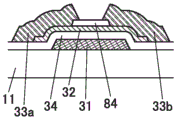
The transistor 30 shown in fig. 6 is a so-called channel-etched bottom-gate transistor. The transistor 30 includes: a conductive layer 31a used as a gate electrode; an insulating layer 34 used as a gate insulating layer; a semiconductor layer 32; and a pair of conductive layers 33a and 33b which function as a source electrode and a drain electrode. A portion of the semiconductor layer 32 which overlaps with the conductive layer 31a is used as a channel formation region. The semiconductor layer 32 is in contact with the conductive layer 33a or the conductive layer 33 b.
Note that the conductive layer 31a corresponds to a part of the wiring G1 in fig. 3C, and the conductive layer 33a corresponds to a part of the wiring S1. The conductive layer 31b and the conductive layer 33c which are described later correspond to the wiring CS and the wiring S2, respectively.
The semiconductor layer 32 preferably uses a metal oxide having semiconductor characteristics (also referred to as an oxide semiconductor). A transistor including an oxide semiconductor can be formed over a large-sized substrate with high yield without requiring a crystallization step required for a transistor including polycrystalline silicon. Further, a transistor including an oxide semiconductor can realize higher field-effect mobility than a transistor including amorphous silicon.
The capacitor 60 includes a conductive layer 31b, an insulating layer 34, and a conductive layer 33 b. Further, a conductive layer 33c is provided on the conductive layer 31b via an insulating layer 34.
An insulating layer 82 and an insulating layer 81 are stacked so as to cover the transistor 30 and the like. A conductive layer 21 serving as a pixel electrode is provided over the insulating layer 81. In the connection portion 38, the conductive layer 21 and the conductive layer 33b are electrically connected through the openings in the insulating layer 81 and the insulating layer 82. The insulating layer 81 is preferably used as a planarization layer. The insulating layer 82 preferably has a function as a protective film for suppressing diffusion of impurities and the like into the transistor 30 and the like. For example, the insulating layer 82 may be formed using an inorganic insulating material, and the insulating layer 81 may be formed using an organic insulating material.
[ examples of sectional Structure 1-2]
Fig. 7 shows an example in which the colored layer 41 is provided on the substrate 11 side. This can simplify the structure on the substrate 12 side.
Note that, in the case where the colored layer 41 is a planarizing film, the insulating layer 81 is not necessarily provided.
[ examples of sectional structures 1 to 3]
In the above examples, a vertical electric field type liquid crystal element in which a pair of electrodes are arranged above and below liquid crystal is used as a liquid crystal element, but the structure of the liquid crystal element is not limited to this, and liquid crystal elements of various types can be used.
Fig. 8 is a schematic cross-sectional view of a display device including a liquid crystal element using a Fringe Field Switching (FFS) mode.
The liquid crystal element 20 includes: a conductive layer 21 used as a pixel electrode; and a conductive layer 23 overlapping with the conductive layer 21 with an insulating layer 83 interposed therebetween. The conductive layer 23 has a slit-like or comb-like top surface shape.
In the above structure, a capacitance is formed in a portion where the conductive layer 21 and the conductive layer 23 overlap each other, and the capacitance can be used as the capacitor 60. This can reduce the area occupied by the pixels, and thus can realize a high-resolution display device. In addition, the aperture ratio can be improved.
Fig. 8 shows a structure in which the conductive layer 23 used as a common electrode is located on the liquid crystal 22 side, but as shown in fig. 9, a structure in which the conductive layer 21 used as a pixel electrode is located on the liquid crystal 22 side may be employed. In the above structure, the conductive layer 21 has a slit-like or comb-like top surface shape.
[ examples of sectional structures 1 to 4]
A case where a light-transmitting conductive film is used as the capacitor 60 or the like will be described below.
The structure shown in fig. 10 is different from the structure illustrated in fig. 6 mainly in the structure of the capacitor 60. The structure shown in fig. 10 is a cross section corresponding to the layout shown in fig. 4A.
A part of the conductive layer 31bt is in contact with and electrically connected to the conductive layer 31 b. A part of the conductive layer 33bt is in contact with and electrically connected to the conductive layer 33 b.
Here, in the case of laminating a metal oxide film and a metal film, when the metal oxide film is formed on the metal film, the surface of the metal film is oxidized, and therefore, the resistance of the metal film itself or the contact resistance between the metal film and the metal oxide film may be increased. Thus, as shown in fig. 10, a conductive layer containing a metal or the like is preferably provided over the conductive layer containing a metal oxide.
[ examples of sectional structures 1 to 5]
Fig. 11 shows a cross section corresponding to the layout shown in fig. 4C.
In fig. 11, a part of the conductive layer 33bt is in contact with the semiconductor layer 32. Therefore, a part of the conductive layer 33bt is used as one of the source electrode and the drain electrode of the transistor 30.
The conductive layer 21 is provided so as to be in contact with a part of the top surface of the conductive layer 33 bt. By including a metal oxide film as each of the conductive layers 21 and 33bt, contact resistance between them can be reduced.
[ examples of sectional structures 1 to 6]
Fig. 12 shows: in an example of the present invention, a conductive layer used as a gate electrode of a transistor and conductive layers used as a source electrode and a drain electrode of the transistor are formed by an exposure technique using a halftone mask, a gray tone mask, or the like, or a multiple exposure technique, using a stacked-layer structure of a conductive film having light-transmitting properties and a conductive film having light-shielding properties. This reduces the number of photomasks required.
Note that, as the laminated film obtained by the above exposure technique, a sectional shape having the following characteristics can be obtained: the end of the upper layer is located inside the end of the lower layer.
In the transistor 30, a conductive layer 31at is provided on the substrate 11 side of the conductive layer 31 a. A pair of conductive layers 33at and 33bt functioning as source and drain electrodes are provided so as to be in contact with the semiconductor layer 32. The conductive layer 33a is provided on the conductive layer 33 at.
A conductive layer 33ct is provided below the conductive layer 33 c.
Here, the manufacturing cost can be reduced as the number of photolithography steps in the manufacturing process of the display device is smaller, that is, the number of masks of the photomask is smaller.
For example, the display device having the structure shown in fig. 6 can be manufactured by five photolithography steps among the steps on the substrate 11 side, that is, a step of forming the conductive layer 31a and the like, a step of forming the semiconductor layer 32, a step of forming the conductive layer 33a and the like, a step of forming the opening to be the connection portion 38, and a step of forming the conductive layer 21. That is, the backplate substrate can be manufactured using five photomasks. On the other hand, on the substrate 12 (counter substrate) side, a photomask is not required when an ink jet method or a screen printing method is used as a method for forming the colored layer 41 and the light-shielding layer 42, which is preferable. For example, in the case where the colored layers 41 and the light-shielding layer 42 of three colors are provided, four or more photomasks can be reduced as compared with the case where the photomasks are formed by photolithography.
The above is a description of an example of the sectional structure.
[ structural example 1 of transistor ]
A structural example of a transistor different from the above-described transistor is described below.
An OS transistor can be formed by using a metal oxide for the semiconductor layer 32 of the transistor described below. In the case of using the OS transistor, the update frequency of the video signal can be set to be extremely low during a period in which the video does not change or during a period in which the change is not more than a certain degree, and reduction in power consumption can be achieved.
In the transistor shown in fig. 13A, an insulating layer 84 is provided over a channel formation region of the semiconductor layer 32. The insulating layer 84 is used as an etching stopper in etching the conductive layers 33a and 33 b.
The transistor shown in fig. 13B has a structure in which an insulating layer 84 extends over the insulating layer 34 so as to cover the semiconductor layer 32. In this case, the conductive layer 33a and the conductive layer 33b are connected to the semiconductor layer 32 through an opening provided in the insulating layer 84.
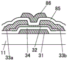
The transistor shown in fig. 13C includes an insulating layer 85 and a conductive layer 86. The insulating layer 85 is provided so as to cover the semiconductor layer 32, the conductive layer 33a, and the conductive layer 33 b. In addition, a conductive layer 86 is provided over the insulating layer 85 and has a region overlapping with the semiconductor layer 32.
The conductive layer 86 is located at a position facing the conductive layer 31 with the semiconductor layer 32 interposed therebetween. When the conductive layer 31 functions as a first gate electrode, the conductive layer 86 can be used as a second gate electrode. By applying the same potential to the conductive layer 31 and the conductive layer 86, the on-state current of the transistor can be increased. The threshold voltage of the transistor can be controlled by supplying a potential for controlling the threshold voltage to one of the conductive layer 31 and the conductive layer 86 and supplying a potential for driving to the other.
Fig. 13A to 13C each show an example in which an end portion of the semiconductor layer 32 is located outside an end portion of the conductive layer 31, but one embodiment of the present invention is not limited thereto. The end of the semiconductor layer 32 may be located inside the end of the conductive layer 31.
The transistor shown in fig. 13D is a top-gate transistor, and a conductive layer 31 serving as a gate electrode is provided over a semiconductor layer 32 (on the side opposite to the surface on which the conductive layer is formed). An insulating layer 34 and a conductive layer 31 are stacked over the semiconductor layer 32. The insulating layer 82 is provided so as to cover the top surface and side end portions of the semiconductor layer 32 and the conductive layer 31. The conductive layer 33a and the conductive layer 33b are provided over the insulating layer 82. The conductive layers 33a and 33b are connected to the semiconductor layer 32 through openings provided in the insulating layer 82.
Note that although an example in which the insulating layer 34 does not exist in a portion which does not overlap with the conductive layer 31 is shown here, the insulating layer 34 may cover the top surface and the side end portions of the semiconductor layer 32.
In the transistor shown in fig. 13D, the physical distance between the conductive layer 31 and each of the conductive layers 33a and 33b is easily pulled, whereby the parasitic capacitance between these conductive layers can be reduced.
The transistor shown in fig. 13E is different from the transistor shown in fig. 13D in that: the transistor shown in fig. 13E includes a conductive layer 87 and an insulating layer 88. The conductive layer 87 has a region overlapping with the semiconductor layer 32. An insulating layer 88 covers the conductive layer 87.
The conductive layer 87 is used as a second gate electrode. Thus, for example, the on-state current can be increased, and the threshold voltage can be controlled.
The above is an explanation of a structural example of the transistor.
[ Cross-sectional Structure example 2]
A cross-sectional structure example of a display device using silicon as a semiconductor layer of a transistor is described below.
[ Cross-sectional Structure example 2-1]
The structure shown in fig. 14 is mainly different from the structure of the above-described cross-sectional structure example 1-1 (fig. 8) in the structure of the transistor 30.
The transistor 30 shown in fig. 14 is a so-called channel-etched bottom-gate transistor. The transistor 30 includes: a conductive layer 31 used as a gate electrode; an insulating layer 34 used as a gate insulating layer; a semiconductor layer 32; a pair of impurity semiconductor layers 35 which function as a source region and a drain region; and a pair of conductive layers 33a and 33b which function as a source electrode and a drain electrode. A portion of the semiconductor layer 32 which overlaps with the conductive layer 31 is used as a channel formation region. The semiconductor layer 32 is in contact with the impurity semiconductor layer 35, and the impurity semiconductor layer 35 is in contact with the conductive layer 33a or the conductive layer 33 b.
As the semiconductor layer 32, a semiconductor containing silicon is preferably used. For example, amorphous silicon, microcrystalline silicon, polycrystalline silicon, or the like can be used. Amorphous silicon is particularly preferable because it can be formed over a large-sized substrate with high yield. The display device according to one embodiment of the present invention can perform favorable display even with a transistor including amorphous silicon having low field-effect mobility. As the amorphous silicon, hydrogenated amorphous silicon (sometimes referred to as a-Si: H) in which dangling bonds are terminated with hydrogen is preferably used.
The impurity semiconductor film constituting the impurity semiconductor layer 35 is formed using a semiconductor to which an impurity element imparting one conductivity type is added. When the transistor is an n-channel transistor, examples of a semiconductor to which an impurity element imparting one conductivity type is added include silicon to which P or As is added. Alternatively, when the transistor is a p-channel transistor, B, for example, may be added as an impurity element imparting one conductivity type, but an n-type transistor is preferably used. Note that the impurity semiconductor layer 35 can also be formed using an amorphous semiconductor or a crystalline semiconductor such as a microcrystalline semiconductor.
[ examples of sectional Structure 2-2]
Fig. 15 shows an example in which the colored layer 41 is provided on the substrate 11 side. As the cross-sectional structure example 2-2 other than the structure of the transistor 30, the cross-sectional structure example 1-2 described above can be referred to.
[ examples of sectional structures 2 to 3]
Fig. 16 and 17 are schematic cross-sectional views of a display device including a liquid crystal element using an FFS mode. Cross-sectional structure examples 2 to 3 other than the structure of the transistor 30 can refer to the above-described cross-sectional structure examples 1 to 3.
The above is a description of the cross-sectional structure example 2.
[ structural example 2 of transistor ]
A structural example of a transistor different from the above is explained below.
The transistor shown in fig. 18A includes a semiconductor layer 37 between the semiconductor layer 32 and the impurity semiconductor layer 35.
The semiconductor layer 37 may be formed using the same semiconductor film as the semiconductor layer 32. The semiconductor layer 37 can be used as an etching stopper layer which prevents the semiconductor layer 32 from being lost by etching when the impurity semiconductor layer 35 is etched. Fig. 18A shows an example in which the semiconductor layer 37 is separated right and left, but a part of the semiconductor layer 37 may cover the channel formation region of the semiconductor layer 32.
In addition, the semiconductor layer 37 may include an impurity at a lower concentration than the impurity semiconductor layer 35. This makes it possible to use the semiconductor layer 37 as a Lightly Doped Drain (LDD) region, thereby suppressing hot carrier degradation when driving a transistor.
In the transistor shown in fig. 18B, an insulating layer 84 is provided over a channel formation region of the semiconductor layer 32. The insulating layer 84 is used as an etching stopper in etching the impurity semiconductor layer 35.
The transistor shown in fig. 18C includes a semiconductor layer 32p instead of the semiconductor layer 32. The semiconductor layer 32p includes a semiconductor film having high crystallinity. For example, the semiconductor layer 32p includes a polycrystalline semiconductor or a single crystal semiconductor. Thereby, a transistor having high field-effect mobility can be realized.
The transistor shown in fig. 18D includes a semiconductor layer 32p in a channel formation region of the semiconductor layer 32. For example, a semiconductor film to be the semiconductor layer 32 is irradiated with laser light or the like to be locally crystallized, whereby a transistor shown in fig. 18D can be formed. Thereby, a transistor having high field-effect mobility can be realized.
The transistor shown in fig. 18E includes a semiconductor layer 32p having crystallinity in a channel formation region of the semiconductor layer 32 of the transistor shown in fig. 18A.
The transistor shown in fig. 18F includes a semiconductor layer 32p having crystallinity in a channel formation region of the semiconductor layer 32 of the transistor shown in fig. 18B.
The above is a description of the structural example 2 of the transistor.
[ shape of conductive layer ]
As a conductive film which can be used as a wiring such as a gate line or a source line, a low-resistance material such as a metal or an alloy can be used, and the above material is preferable because the wiring resistance can be reduced. In the case of manufacturing a display device of a large screen, it is also effective to increase the width of the wiring. However, since the conductive film does not transmit visible light, the following problem may occur in a transmissive liquid crystal display device: the width of the wiring itself increases; and the aperture ratio decreases as the number of wirings increases.
By improving the shape of the end portion of the conductive film, light from the backlight unit can be efficiently extracted.
Fig. 19A is a cross-sectional view of the conductive layer 33 constituting a source line and the like and its vicinity. The conductive layer 33 has an inverted tapered end.
Here, the taper angle means: the angle formed by the bottom surface (surface in contact with the surface to be formed) and the side surface at the end of the film. The cone angle is greater than 0 ° and less than 180 °. In addition, a taper smaller than 90 ° is called a forward taper, and a taper larger than 90 ° is called an inverted taper.
As shown in fig. 19A, by making the conductive layer 33 have an inverted cone shape, part of the light 50 from the backlight unit is reflected by the side surface of the conductive layer 33 and reaches the liquid crystal 22. As a result, the light extraction efficiency can be improved as compared with the case where the side surface of the conductive layer 33 is vertical or tapered.
Here, the taper angle of the conductive layer 33 is preferably greater than 90 ° and less than 135 °, more preferably 91 ° or more and 120 ° or less, and further preferably 95 ° or more and 110 ° or less.
In addition, fig. 19B illustrates an example in which the conductive layer 31 constituting the gate line or the like has an inverted conical shape. By having the conductive layer 31 in an inverted cone shape in addition to the conductive layer 33, light extraction efficiency can be more effectively improved.
The above is an explanation of the shape of the wiring.
[ constituent elements ]
The following describes the above-described components.
Substrate
The substrate included in the display panel may use a material having a flat surface. The substrate on the side from which light is extracted from the display element is formed using a material that transmits the light. For example, a material such as glass, quartz, ceramic, sapphire, or an organic resin can be used.
By using a substrate having a small thickness, the weight and thickness of the display panel can be reduced. By using a substrate which is thin enough to have flexibility, a display panel having flexibility can be realized. Alternatively, glass or the like thin enough to have flexibility may be used as the substrate. Alternatively, a composite material in which glass and a resin material are bonded together with an adhesive layer may be used.
Transistor
The transistor includes a conductive layer used as a gate electrode, a semiconductor layer, a conductive layer used as a source electrode, a conductive layer used as a drain electrode, and an insulating layer used as a gate insulating layer.
Note that the structure of a transistor included in the display device according to one embodiment of the present invention is not particularly limited. For example, a planar transistor, a staggered transistor, or an inverted staggered transistor may be used. A top gate type transistor or a bottom gate type transistor may also be used. Gate electrodes may be provided above and below the channel.
The crystallinity of a semiconductor material used for a transistor is not particularly limited, and an amorphous semiconductor or a semiconductor having crystallinity (a microcrystalline semiconductor, a polycrystalline semiconductor, a single crystal semiconductor, or a semiconductor partially having a crystalline region) can be used. When a semiconductor having crystallinity is used, deterioration in characteristics of the transistor can be suppressed, and therefore, the semiconductor is preferable.
As a semiconductor material used for a transistor, a metal oxide having an energy gap of 2eV or more, preferably 2.5eV or more, and more preferably 3eV or more can be used. As a typical example, a metal oxide containing indium may be mentioned, and CAC-OS described later may be used.
Since the off-state current of a transistor using a metal oxide having a wider band gap and a smaller carrier density than that of silicon is low, charges stored in a capacitor connected in series with the transistor can be held for a long period of time.
The semiconductor layer may be a film represented by "In-M-Zn based oxide" containing indium, zinc, and M (metal such as aluminum, titanium, gallium, germanium, yttrium, zirconium, lanthanum, cerium, tin, neodymium, or hafnium).
When the metal oxide contained In the semiconductor layer is an In-M-Zn-based oxide, the atomic number ratio of the metal elements of the sputtering target for forming the In-M-Zn oxide film preferably satisfies in.M and Zn.M. The atomic number ratio of the metal elements of such a sputtering target is preferably 1:1:1, 1:1:1.2, 3:1:2, 4:2:3, 4:2:4.1, 5:1:6, 5:1:7, 5:1:8, or the like. Note that the atomic number ratios of the semiconductor layers to be formed may be varied within a range of ± 40% of the atomic number ratio of the metal element in the sputtering target, respectively.
The bottom-gate transistor described in this embodiment is preferable because the number of manufacturing steps can be reduced. When a metal oxide formed at a lower temperature than polysilicon is used for a bottom-gate transistor, and a material having low heat resistance can be used as a wiring, an electrode, or a substrate under a semiconductor layer, the range of selection of materials can be expanded. For example, a glass substrate or the like having an extremely large area can be suitably used.
As the semiconductor layer, a metal oxide film having a low carrier density can be used. For example, the semiconductor layer has a carrier density of 1 × 10¹⁷/cm3Hereinafter, it is preferably 1 × 10¹⁵/cm3Hereinafter, more preferably 1 × 10¹³/cm3Hereinafter, more preferably 1 × 10¹¹/cm3Hereinafter, more preferably less than 1 × 10¹⁰/cm3And is 1X 10⁻⁹/cm3The above metal oxides. Such metal oxides are referred to as high purity intrinsic or substantially high purity intrinsic metal oxides. The metal oxide has a low impurity concentration and a low defect state density, and thus can be said to be a metal oxide having stable characteristics.
Note that, without being limited to the above description, a material having an appropriate composition may be used in accordance with semiconductor characteristics and electrical characteristics (field effect mobility, threshold voltage, and the like) of a transistor to be required. It is preferable to set the carrier density, impurity concentration, defect density, atomic number ratio of a metal element to oxygen, interatomic distance, density, and the like of the semiconductor layer to appropriate values in order to obtain desired semiconductor characteristics of the transistor.
When silicon or carbon, which is one of the group 14 elements, is contained in the metal oxide included in the semiconductor layer, oxygen vacancies in the semiconductor layer increase, which makes the semiconductor layer n-type. Therefore, the concentration of silicon or carbon in the semiconductor layer (measured by secondary ion mass spectrometry) was 2 × 10¹⁸atoms/cm3Hereinafter, 2 × 10 is preferable17atoms/cm3The following.
When an alkali metal or an alkaline earth metal is bonded to a metal oxide, carriers are generated, and an off-state current of a transistor may increase. Therefore, the concentration of alkali metal or alkaline earth metal of the semiconductor layer as measured by secondary ion mass spectrometry is 1X 10¹⁸atoms/cm3Hereinafter, 2 × 10 is preferable16atoms/cm3The following.
When the metal oxide included in the semiconductor layer contains nitrogen, electrons serving as carriers are generated, and the carrier density increases, so that the semiconductor layer is easily made n-type. As a result, a transistor including a metal oxide containing nitrogen easily has a normally-on characteristic. Therefore, the nitrogen concentration of the semiconductor layer measured by secondary ion mass spectrometry is preferably 5 × 10¹⁸atoms/cm3The following.
Oxide semiconductors are classified into single crystal oxide semiconductors and non-single crystal oxide semiconductors. Examples of the non-single crystal oxide semiconductor include a c-axis oriented crystalline oxide semiconductor (CAAC-OS), a polycrystalline oxide semiconductor, a nanocrystalline oxide semiconductor (nc-OS), an amorphous oxide semiconductor (a-like OS), and the like.
As a semiconductor layer of the transistor disclosed as one embodiment of the present invention, a Cloud-Aligned composite oxide semiconductor (CAC-OS) can be used.
In addition, the non-single crystal oxide semiconductor or CAC-OS can be used as appropriate for the semiconductor layer of the transistor disclosed in one embodiment of the present invention. As the non-single crystal oxide semiconductor, nc-OS or CAAC-OS can be used as appropriate.
In one embodiment of the present invention, CAC-OS is preferably used as a semiconductor layer of a transistor. By using the CAC-OS, the transistor can have high electrical characteristics or high reliability.
The semiconductor layer may be a mixed film of two or more kinds in the following region: a region of CAAC-OS, a region of polycrystalline oxide semiconductor, a region of nc-OS, a region of amorphous oxide semiconductor, and a region of amorphous oxide semiconductor. The hybrid film sometimes has, for example, a single-layer structure or a laminated structure including two or more of the above-described regions.
< construction of CAC-OS >
Hereinafter, a configuration of a closed-aligned composite oxide semiconductor (CAC-OS) that can be used for the transistor disclosed in one embodiment of the present invention will be described.
The CAC-OS has, for example, a configuration in which elements contained in a metal oxide are unevenly distributed. Each of the materials containing the unevenly distributed elements has a size of 0.5nm or more and 10nm or less, preferably 1nm or more and 2nm or less or an approximate size. Note that in the following description of the metal oxide, a state in which one or more metal elements are unevenly distributed and a region containing the metal elements is mixed is also referred to as a mosaic shape or a patch shape. The size of the region is 0.5nm or more and 10nm or less, preferably 1nm or more and 2nm or less or approximately.
Note that the metal oxide preferably contains at least indium. Particularly preferably indium and zinc. In addition, one or more of aluminum, gallium, yttrium, copper, vanadium, beryllium, boron, silicon, titanium, iron, nickel, germanium, zirconium, molybdenum, lanthanum, cerium, neodymium, hafnium, tantalum, tungsten, magnesium, and the like may be contained.
For example, as the CAC-OS, an In-Ga-Zn oxide having a CAC composition (In-Ga-Zn oxide may be particularly referred to as CAC-IGZO) has a material classification of indium oxide (InO)X1X1 is a real number greater than 0) or indium zinc oxide (In)X2ZnY2OZ2X2, Y2, and Z2 are real numbers greater than 0) and gallium oxide (GaO)X3X3 is a real number greater than 0) or gallium zinc oxide (GaX4ZnY4OZ4X4, Y4, and Z4 are real numbers larger than 0) to form a mosaic shape. Further, InO constituting a mosaic shapeX1Or InX2ZnY2OZ2Are uniformly distributed in the film. The above-mentioned formation is also referred to as a cloud formation.
In other words, the CAC-OS is of GaOX3A region containing as a main component InX2ZnY2OZ2Or InOX1A composite metal oxide having a structure in which regions of the main component are mixed together. Note that In this specification, for example, when the atomic number ratio of In to the element M In the first region is larger than the atomic number ratio of In to the element M In the second region, the In concentration In the first region is higher than that In the second region.
Note that a compound containing In, Ga, Zn, and O is also referred to as IGZO. A typical example of IGZO is InGaO3(ZnO)m1A crystalline compound represented by (m1 is a natural number) and In(1+x0)Ga(1-x0)O3(ZnO)m0A crystalline compound represented by (-1. ltoreq. x 0. ltoreq.1, m0 is an arbitrary number).
The crystalline compound has a single crystal structure, a polycrystalline structure, or a CAAC structure. Note that the CAAC structure is a crystal structure in which nanocrystals of IGZO have c-axis orientation and are connected in a non-oriented manner on the a-b plane.
On the other hand, CAC-OS is related to the material composition of the metal oxide. In the material composition In which CAC-OS contains In, Ga, Zn, and O, a region of nanoparticles containing Ga as a main component is observed In a part of CAC-OS and a region of nanoparticles containing In as a main component is observed In a part of CAC-OS. The regions of these nanoparticles are irregularly dispersed and formed into a mosaic shape. Thus, the crystal structure is a secondary factor of CAC-OS.
Note that the CAC-OS does not have a stacked structure including two or more films having different atomic number ratios. For example, the film does not have a structure composed of two layers of a film containing In as a main component and a film containing Ga as a main component.
Note that GaO is sometimes not observedX3A region containing as a main component InX2ZnY2OZ2Or InOX1Is a well-defined boundary between regions of major composition.
When the CAC-OS contains one or more selected from aluminum, yttrium, copper, vanadium, beryllium, boron, silicon, titanium, iron, nickel, germanium, zirconium, molybdenum, lanthanum, cerium, neodymium, hafnium, tantalum, tungsten, magnesium, and the like In place of gallium, nano-particle-shaped regions containing the selected metal element as a main component are observed In a part of the CAC-OS and nano-particle-shaped regions containing In as a main component are observed In a part of the CAC-OS, and these nano-particle-shaped regions are irregularly dispersed to form a mosaic.
The CAC-OS can be formed by, for example, sputtering without intentionally heating the substrate. In the case of forming the CAC-OS by the sputtering method, as the film forming gas, one or more selected from an inert gas (typically argon), an oxygen gas, and a nitrogen gas may be used. The lower the flow ratio of the oxygen gas in the total flow of the film forming gas at the time of film formation, the better, for example, the flow ratio of the oxygen gas is set to 0% or more and less than 30%, preferably 0% or more and 10% or less.
The CAC-OS has the following characteristics: when measured by an out-of-plane method, which is one of X-ray diffraction (XRD) measurements, using a theta/2 theta scan, no clear peak is observed. That is, it was found from the X-ray diffraction that the orientation in the a-b plane direction and the c-axis direction was not present in the measurement region.
In the electron diffraction pattern of CAC-OS obtained by irradiating an electron beam having a beam diameter of 1nm (also referred to as a nano-sized electron beam), an annular high-luminance region and a plurality of bright spots in the annular region were observed. From this, it is known that the crystal structure of CAC-OS has a nanocrystalline (nc) structure having no orientation in the plane direction and the cross-sectional direction, based on the electron diffraction pattern.
For example, from the energy dispersive X-ray analysis (EDX) image, it was confirmed that: the In-Ga-Zn oxide having a structure of CAC-OS has a structure of GaOX3A region containing as a main component and InX2ZnY2OZ2Or InOX1The main component region is unevenly distributed and mixed.
The structure of CAC-OS is different from that of an IGZO compound in which metal elements are uniformly distributed, and has different properties from that of the IGZO compound. In other words, CAC-OS has a GaOX3Etc. as main component and InX2ZnY2OZ2Or InOX1The regions of the main component are separated to form a mosaic.
In is formed byX2ZnY2OZ2Or InOX1The conductivity of the region having the main component is higher than that of GaOX3Etc. of the region having the main component. In other words, when carriers flow InX2ZnY2OZ2Or InOX1The region containing the main component exhibits conductivity of the metal oxide. Therefore, when In is usedX2ZnY2OZ2Or InOX1When the region as the main component is distributed in a cloud shape in the metal oxide, high field-effect mobility (μ) can be achieved.
On the other hand, with GaOX3The insulating property of the region containing the above-mentioned component is higher than that of InX2ZnY2OZ2Or InOX1The insulating property of the region that is the main component. In other words, when GaO is usedX3When the region containing the metal oxide as a main component is distributed, leakage current can be suppressed and a good switching operation can be realized.
Therefore, when CAC-OS is used for the semiconductor element, the heat radiation is caused by GaOX3Insulation property of the like and the cause of InX2ZnY2OZ2Or InOX1Can realize high-pass current (I)on) And high field effect mobility (μ).
The semiconductor element using the CAC-OS has high reliability. Therefore, the CAC-OS is suitable for various semiconductor devices including a display.
Since the transistor having the CAC-OS in the semiconductor layer has high field effect mobility and high driving capability, a display device with a narrow frame width can be provided by using the transistor for a driver circuit (typically, a scan line driver circuit which generates a gate signal). In addition, by using the transistor for a signal line driver circuit included in the display device (particularly, a demultiplexer connected to an output terminal of a shift register included in the signal line driver circuit), the number of wirings connected to the display device can be reduced.
The transistor having the CAC-OS in the semiconductor layer does not require a laser crystallization process required for a transistor including low-temperature polysilicon. Thus, even if a display device is formed using a large-area substrate, manufacturing cost can be reduced. Further, in a large-sized display device with High resolution such as Ultra High Definition ("4K resolution", "4K 2K", "4K") and Super High Definition ("8K resolution", "8K 4K", "8K"), a transistor having a CAC-OS in a semiconductor layer is preferably used for a driver circuit and a display portion, because writing and display defects can be reduced in a short time.
In addition, silicon can be used for a semiconductor in which a channel of a transistor is formed. In particular, when amorphous silicon is used as silicon, transistors can be formed over a large substrate with high yield. When amorphous silicon is used, hydrogenated amorphous silicon (sometimes referred to as a-Si: H) in which dangling bonds are terminated with hydrogen is preferably used.
Further, crystalline silicon such as microcrystalline silicon, polycrystalline silicon, or single crystal silicon can be used. In particular, polycrystalline silicon can be formed at a low temperature compared to single crystalline silicon, and has higher field effect mobility and reliability than amorphous silicon.
When silicon is used, an impurity semiconductor layer to which an impurity element imparting one conductivity type is added is preferably provided between the semiconductor layer and the source electrode or the drain electrode. When the transistor is an n-type transistor, examples of a semiconductor to which an impurity element imparting one conductivity type is added include silicon to which P or As is added. When the transistor is a p-channel transistor, B, for example, can be added as an impurity element imparting one conductivity type, but an n-channel transistor is preferably used. Note that the impurity semiconductor layer can be formed using an amorphous semiconductor or a crystalline semiconductor such as a microcrystalline semiconductor.
The bottom-gate transistor described in this embodiment is preferable because the number of manufacturing steps can be reduced. When amorphous silicon which can be formed at a lower temperature than polycrystalline silicon is used for the semiconductor layer, a material having low heat resistance can be used for a wiring, an electrode, or a substrate below the semiconductor layer, and thus the range of selection of materials can be widened. For example, a glass substrate or the like having an extremely large area can be suitably used. On the other hand, a top gate transistor is preferable because an impurity region is easily formed in self-alignment, and unevenness in characteristics and the like can be reduced. When polycrystalline silicon, single crystal silicon, or the like is used, a top gate transistor is particularly preferable in some cases.
Conductive layer
Examples of a material which can be used for a gate electrode, a source electrode, and a drain electrode of a transistor, a conductive layer which is used for various wirings, electrodes, and the like included in a display device include any metal such as aluminum, titanium, chromium, nickel, copper, yttrium, zirconium, molybdenum, silver, tantalum, or tungsten, or an alloy containing any of the metals as a main component. Single layer or stacked structures comprising any of the above materials may be used. For example, a single-layer structure of an aluminum film containing silicon, a two-layer structure of an aluminum film stacked over a titanium film, a two-layer structure of an aluminum film stacked over a tungsten film, a two-layer structure of a copper film stacked over a copper-magnesium-aluminum alloy film, a two-layer structure of a copper film stacked over a titanium film, a two-layer structure of a copper film stacked over a tungsten film, a three-layer structure of a titanium film or a titanium nitride film, an aluminum film or a copper film, and a titanium film or a titanium nitride film stacked in this order, and a three-layer structure of a molybdenum film or a molybdenum nitride film, an aluminum film or a copper film, and a molybdenum film or a molybdenum nitride film stacked in this order are given. In addition, oxides such as indium oxide, tin oxide, and zinc oxide can be used. The use of copper containing manganese is preferable because the controllability of the shape during etching can be improved.
As a light-transmitting conductive material which can be used for a conductive layer included in various wirings, electrodes, and the like of a display device in addition to a gate, a source, and a drain of a transistor, a conductive oxide such as indium oxide, indium tin oxide, indium zinc oxide, and zinc oxide to which gallium is added, or graphene can be used. Alternatively, a metal material such as gold, silver, platinum, magnesium, nickel, tungsten, chromium, molybdenum, iron, cobalt, copper, palladium, or titanium, or an alloy material containing the metal material can be used. Alternatively, a nitride (e.g., titanium nitride) of the metal material or the like may also be used. In addition, when a metal material, an alloy material (or a nitride thereof) is used, it can be formed to be thin to have light transmittance. A stacked film of any of the above materials can be used as the conductive layer. For example, a laminated film of indium tin oxide and an alloy of silver and magnesium is preferably used because conductivity can be improved. The above materials can be used for a conductive layer included in various wirings, electrodes, and the like of a display device, or a conductive layer included in a display element (for example, a conductive layer used as a pixel electrode and a common electrode).
As the light-transmitting conductive material, an oxide semiconductor (oxide conductor: OC) whose resistance is reduced by adding an impurity element or the like is preferably used.
Insulating layer
As an insulating material that can be used for each insulating layer, for example, a resin such as acrylic or epoxy resin, a resin having a siloxane bond, an inorganic insulating material such as silicon oxide, silicon oxynitride, silicon nitride oxide, silicon nitride, or aluminum oxide can be used.
Examples of the insulating film having low water permeability include a film containing nitrogen and silicon (for example, a silicon nitride film and a silicon oxynitride film), a film containing nitrogen and aluminum (for example, an aluminum nitride film), and the like. Alternatively, a silicon oxide film, a silicon oxynitride film, an aluminum oxide film, or the like can be used.
Liquid crystal element
As the liquid crystal element, for example, a liquid crystal element using a Vertical Alignment (VA) mode can be used. As the vertical alignment mode, a multi-domain vertical alignment (MVA) mode, a vertical alignment configuration (PVA) mode, an Advanced Super Vision (ASV) mode, or the like can be used.
The liquid crystal element can use various modes: for example, in addition to the VA mode, a Twisted Nematic (TN) mode, an in-plane switching (IPS) mode, a Fringe Field Switching (FFS) mode, an axisymmetric aligned microcell (ASM) mode, an Optically Compensated Bend (OCB) mode, a Ferroelectric Liquid Crystal (FLC) mode, an antiferroelectric liquid crystal (AFLC) mode, an Electrically Controlled Birefringence (ECB) mode, a guest-host mode, or the like may be used.
The liquid crystal element controls the transmission or non-transmission of light by the optical modulation action of liquid crystal. Note that the optical modulation action of the liquid crystal is controlled by an electric field (including a transverse electric field, a longitudinal electric field, or a tilt direction electric field) applied to the liquid crystal. Thermotropic liquid crystal, low molecular liquid crystal, Polymer Dispersed Liquid Crystal (PDLC), Polymer Network Liquid Crystal (PNLC), ferroelectric liquid crystal, antiferroelectric liquid crystal, or the like can be used as the liquid crystal used for the liquid crystal element. These liquid crystal materials exhibit a cholesteric phase, a smectic phase, a cubic phase, a chiral nematic phase, and isotropy, depending on conditions.
As the liquid crystal material, any of positive type liquid crystal and negative type liquid crystal can be used depending on the mode or design used.
In order to control the alignment of the liquid crystal, an alignment film may be provided. In the case of employing the transverse electric field mode, a liquid crystal exhibiting a blue phase without using an alignment film may be used. The blue phase is one of liquid crystal phases, and refers to a liquid crystal phase that appears immediately before a cholesteric phase is converted into an isotropic phase when the temperature of cholesteric liquid crystal is increased. Since the blue phase occurs only in a narrow temperature range, a liquid crystal composition in which a chiral agent is mixed by several wt% or more is used for the liquid crystal layer to widen the temperature range. The liquid crystal composition containing a liquid crystal exhibiting a blue phase and a chiral agent has a fast response speed and is optically isotropic, thereby requiring no alignment treatment and reducing viewing angle dependence. Since the alignment film does not need to be provided and the rubbing treatment is not needed, electrostatic breakdown due to the rubbing treatment can be prevented, and defects and breakage of the liquid crystal display device in the manufacturing process can be reduced.
Examples of the liquid crystal element include a transmissive liquid crystal element, a reflective liquid crystal element, and a semi-transmissive liquid crystal element.
In one embodiment of the present invention, a transmissive liquid crystal element can be suitably used in particular.
When a transmissive liquid crystal element or a semi-transmissive liquid crystal element is used, two polarizing plates are provided so as to sandwich a pair of substrates. In addition, a backlight is provided outside one polarizing plate. The backlight may be a direct type backlight or an edge light type backlight. Since local dimming (local dimming) is easy and contrast can be improved, it is preferable to use a direct type backlight including Light Emitting Diodes (LEDs). The use of an edge-lit type backlight is preferable because the thickness of a module including the backlight can be thinned.
One embodiment of the present invention can be used as a clear display by turning off an edge-light type backlight.
Coloured layer
Examples of materials that can be used for the colored layer include metal materials, resin materials, and resin materials containing pigments or dyes.
Light-shielding layer
Examples of materials that can be used for the light-shielding layer include carbon black, titanium black, metals, metal oxides, and composite oxides containing a solid solution of a plurality of metal oxides. The light-shielding layer may be a film containing a resin material or a thin film containing an inorganic material such as a metal. A laminated film of films including materials of the colored layers may be used as the light-shielding layer. For example, a stacked structure of a film including a material of a colored layer for transmitting light of a certain color and a film including a material of a colored layer for transmitting light of another color may be employed. Since the process can be simplified in addition to the use of the same equipment, the colored layer and the light-shielding layer are preferably formed using the same material.
The above is a description of each constituent element.
At least any part of the configuration examples, the manufacturing method examples, and the drawings corresponding to these examples, and the like shown in this embodiment mode can be implemented in appropriate combination with any of the other configuration examples, the other manufacturing method examples, or the other drawings, and the like.
At least a part of this embodiment mode can be implemented in appropriate combination with any other embodiment mode described in this specification.
(embodiment mode 2)
In this embodiment, an example of a method for crystallizing polycrystalline silicon and a laser crystallization apparatus which can be used for a semiconductor layer of a transistor will be described.
In order to form a polycrystalline silicon layer having good crystallinity, it is preferable to form an amorphous silicon layer over a substrate and irradiate the amorphous silicon layer with laser light to crystallize the amorphous silicon layer. For example, a linear beam is used as the laser beam, and the linear beam is irradiated to the amorphous silicon layer while moving the substrate, whereby a polycrystalline silicon layer can be formed in a desired region on the substrate.
The method using the line beam has a relatively high throughput. However, since the laser beam is irradiated to one region a plurality of times so as to move relative to the region, the above method easily causes uneven crystallinity due to output variation of the laser beam and variation in beam distribution caused by the output variation. For example, when a semiconductor layer crystallized by this method is used for a transistor included in a pixel of a display device, irregular streaks due to unevenness in crystallinity may appear when an image is displayed.
The length of the linear beam is preferably equal to or longer than the length of one side of the substrate, but is limited by the output of the laser oscillator and the structure of the optical system. Therefore, when a large substrate is irradiated, it is practical to irradiate the laser light back into the substrate surface. Therefore, a region where the laser light is repeatedly irradiated is generated. Since the crystallinity of this region is likely to be different from that of the other regions, the region may show unevenness.
In order to suppress the above problem, the amorphous silicon layer formed over the substrate may be locally irradiated with laser light to be crystallized. By locally irradiating the laser beam, a polycrystalline silicon layer with little crystallinity unevenness is easily formed.
Fig. 20A illustrates a method of locally irradiating a laser light to an amorphous silicon layer formed over a substrate.
The laser beam 826 emitted from the optical system unit 821 is reflected by the mirror 822 and enters the microlens array 823. The microlens array 823 condenses the laser light 826 to form a plurality of laser beams 827.
The substrate 830 having the amorphous silicon layer 840 formed thereon is fixed to the stage 815. By irradiating the amorphous silicon layer 840 with the plurality of laser beams 827, a plurality of polysilicon layers 841 can be simultaneously formed.
Each microlens included in the microlens array 823 is preferably arranged at a pixel pitch of the display device. Alternatively, the microlenses may be arranged at intervals of an integral multiple of the pixel pitch. In any of the above-described methods, the polycrystalline silicon layer can be formed in the regions corresponding to all the pixels by repeatedly moving the stage 815 in the X direction or the Y direction and irradiating the laser beam.
For example, in the case where the microlens array 823 has M rows and N columns of microlenses (M and N are natural numbers) at a pixel pitch, first, by irradiating a laser light to a specified start position, the polysilicon layer 841 can be formed in M rows and N columns. Then, the stage 815 is moved in the row direction by a distance corresponding to N columns and laser light is irradiated, and a polysilicon layer 841 is further formed in M rows and N columns. Thereby, the polysilicon layer 841 of M rows and 2N columns may be formed. By repeating this step, a plurality of polysilicon layers 841 can be formed in a desired region. When the laser light is irradiated in a folded state, the following steps are repeated: moving the stage 815 in the row direction by a distance equivalent to N columns; irradiating laser; moving the stage 815 in the column direction by a distance equivalent to M rows; and irradiating laser.
Further, by appropriately adjusting the oscillation frequency of the laser beam and the moving speed of the stage 815, even when a method of moving the stage 815 in one direction while irradiating the laser beam is employed, a polycrystalline silicon layer can be formed at a pixel pitch.
The size of the laser beam 827 can be set to the area of the entire semiconductor layer including one transistor, for example. Alternatively, the area of the entire channel region including one transistor may be set. Alternatively, the area of a part of the channel region including one transistor may be set. The dimensions can be appropriately selected from the areas in accordance with the electrical characteristics of the transistor to be required.
In addition, in the case of manufacturing a display device in which one pixel includes a plurality of transistors, the size of the laser beam 827 may be set to an area of the extent of the entire semiconductor layer including each transistor within one pixel. The size of the laser beam 827 may be the area of the entire semiconductor layer including transistors in a plurality of pixels.
As shown in fig. 21A, a mask 824 may be provided between the mirror 822 and the microlens array 823. The mask 824 includes a plurality of openings corresponding to the respective microlenses. The shape of the opening can be reflected to the shape of the laser beam 827, and as shown in fig. 21A, in the case where the mask 824 includes a circular opening, the circular laser beam 827 can be obtained. In the case where the mask 824 includes rectangular openings, a rectangular laser beam 827 may be obtained. For example, the mask 824 is effective when only the channel region of the transistor is to be crystallized. As shown in fig. 21B, a mask 824 may be provided between the optical system unit 821 and the mirror 822.
Fig. 20B is a perspective view illustrating a main configuration of a laser crystallization apparatus that can be used in the local laser irradiation step. The laser crystallization apparatus includes a moving mechanism 812, a moving mechanism 813, and a stage 815, which are components of an X-Y stage. The laser crystallization apparatus further includes a laser oscillator 820 for shaping the laser beam 827, an optical system unit 821, a mirror 822, and a microlens array 823.
The moving mechanisms 812 and 813 each have a function of performing reciprocating linear motion in the horizontal direction. As a mechanism for supplying power to the moving mechanism 812 and the moving mechanism 813, for example, a ball screw mechanism 816 driven by a motor or the like can be used. Since the moving directions of the moving mechanism 812 and the moving mechanism 813 intersect perpendicularly, the stage 815 fixed to the moving mechanism 813 can move freely in the X direction and the Y direction.
The stage 815 includes a fixing mechanism such as a vacuum suction mechanism, and can fix the substrate 830. Further, the stage 815 may include a heating mechanism as necessary. Although not shown, the stage 815 may include an elastic ejecting rod and a vertical moving mechanism thereof, and may move the substrate 830 in a vertical direction when the substrate 830 and the like are carried in or out.
The laser oscillator 820 is preferably a pulse laser, but may be a CW laser as long as it can output light having a wavelength and intensity suitable for the purpose of processing. Typically, an excimer laser capable of irradiating ultraviolet light having a wavelength of 351nm to 353nm (XeF), 308nm (XeCl), or the like is used. Alternatively, a double harmonic (515nm, 532nm, etc.) or triple harmonic (343nm, 355nm, etc.) of solid-state laser light such as YAG laser light or fiber laser light may be used. A plurality of laser oscillators 820 may also be provided.
The optical system unit 821 includes, for example, a mirror, a beam expander, a beam homogenizer, and the like, and can make the in-plane distribution of the energy of the laser light 825 emitted from the laser oscillator 820 uniform and expanded.
As the mirror 822, for example, a dielectric multilayer film mirror may be used, and the mirror may be provided so that the incident angle of the laser beam becomes substantially 45 °. The microlens array 823 may have a shape in which a plurality of convex lenses are provided on the top surface or the top bottom surface of a quartz plate, for example.
By using the laser crystallization apparatus, a polycrystalline silicon layer with less uneven crystallinity can be formed.
At least a part of this embodiment mode can be implemented in appropriate combination with any other embodiment mode described in this specification.
(embodiment mode 3)
In this embodiment, an electronic device according to an embodiment of the present invention will be described with reference to the drawings.
Each of the electronic devices illustrated below is an electronic device including the display device according to one embodiment of the present invention in a display portion. The electronic device is capable of achieving high resolution. In addition, the electronic device can realize both high resolution and a large screen.
The display portion of the electronic device according to one embodiment of the present invention can display an image having a resolution of, for example, 4K2K, 8K4K, 16K8K or higher with full high definition. The screen size of the display portion may be 20 inches or more, 30 inches or more, 50 inches or more, 60 inches or more, or 70 inches or more in diagonal.
Examples of the electronic device include: electronic devices having a large screen, such as a television device, a desktop or notebook personal computer, a display for a computer or the like, a digital signage, a large-sized game machine (e.g., a pachinko machine), and the like; cameras such as digital cameras, digital video cameras, digital photo frames, and the like; a mobile phone; a portable game machine; a portable information terminal; and a sound reproducing device.
The electronic device or the lighting device of one embodiment of the present invention may be assembled along a curved surface of an inner wall or an outer wall of a house or a tall building, an interior trim or an exterior trim of an automobile.
The electronic device of one embodiment of the present invention may also include an antenna. By receiving the signal through the antenna, an image, data, or the like can be displayed on the display unit. When the electronic device includes an antenna and a secondary battery, the antenna may also be used for non-contact power transmission.
The electronic device of one embodiment of the present invention may also include a sensor (the sensor has force, displacement, position, velocity, acceleration, angular velocity, rotational speed, distance, light, liquid, magnetism, temperature, chemical substance, sound, time, hardness, electric field, current, voltage, electric power, radiation, flow, humidity, inclination, vibration, smell, or infrared ray).
The electronic device according to one embodiment of the present invention may have various functions, for example, a function of displaying various information (a still image, a moving image, a character image, or the like) on the display portion; a function of a touch panel; a function of displaying a calendar, date, time, or the like; functions of executing various software (programs); a function of performing wireless communication; a function of reading out a program or data stored in a storage medium; and the like.
Fig. 22A shows an example of a television device. In the television set 7100, a display portion 7000 is incorporated in a housing 7101. Here, the housing 7101 is supported by a bracket 7103.
The display device according to one embodiment of the present invention can be applied to the display portion 7000.
The operation of the television apparatus 7100 shown in fig. 22A can be performed by using an operation switch provided in the housing 7101 or a remote controller 7111 which is additionally provided. In addition, display unit 7000 may be provided with a touch sensor. The television device 7100 can also be operated by touching the display portion 7000 with a finger or the like. The remote controller 7111 may be provided with a display unit for displaying data output from the remote controller 7111. By using the operation keys or the touch panel provided in the remote controller 7111, the channel and the volume can be operated, and the image displayed on the display portion 7000 can be operated.
The television device 7100 includes a receiver, a modem, and the like. General television broadcasting can be received by using a receiver. The television apparatus is connected to a communication network of a wired or wireless system via a modem, and performs information communication in one direction (from a sender to a receiver) or in two directions (between a sender and a receiver or between receivers).
Fig. 22B shows a notebook personal computer 7200. The notebook personal computer 7200 includes a housing 7211, a keyboard 7212, a pointing device 7213, an external connection port 7214, and the like. A display portion 7000 is incorporated in the housing 7211.
The display device according to one embodiment of the present invention can be applied to the display portion 7000.
Fig. 22C and 22D show examples of the digital signage.
Fig. 22D shows the digital signage 7400 disposed on a cylindrical post 7401. The digital signage 7400 includes a display 7000 provided along the curved surface of the pillar 7401.
The display device according to one embodiment of the present invention can be applied to each display portion 7000 shown in fig. 22C and 22D.
The larger the area of display unit 7000 is, the larger the amount of information that can be provided at a time. Further, the larger the display portion 7000 is, the more attractive the attention is, and for example, the advertisement effect can be improved.
Since the touch panel can display not only a still image or a moving image but also be intuitively operated by the user, it is preferable to use the touch panel for the display portion 7000. When the display device according to one embodiment of the present invention is used for providing information such as route information and traffic information, usability can be improved by intuitive operations.
As shown in fig. 22C and 22D, it is preferable that digital signage 7300 or digital signage 7400 be linked to information terminal 7311 or information terminal 7411, such as a smartphone, carried by the user by wireless communication. For example, the advertisement information displayed on the display portion 7000 may be displayed on the screen of the information terminal 7311 or 7411. Further, by operating information terminal 7311 or 7411, the display of display unit 7000 can be switched.
Further, a game can be executed on the digital signboard 7300 or 7400 with the screen of the information terminal 7311 or 7411 as an operation unit (controller). Thus, a plurality of persons can participate in the game at the same time, and enjoy the game.
At least a part of this embodiment mode can be implemented in appropriate combination with any other embodiment mode described in this specification.
(embodiment mode 4)
In this embodiment, an example of a television device to which a display device according to an embodiment of the present invention is applied will be described with reference to the drawings.
Fig. 23A is a block diagram showing the television apparatus 600.
Note that in the block diagrams attached to this specification, the constituent elements are classified according to their functions and represented by independent blocks, but it is difficult for the actual constituent elements to be clearly divided according to the functions, and one constituent element may have a plurality of functions.
The television device 600 includes a control unit 601, a storage unit 602, a communication control unit 603, an image processing circuit 604, a decoder circuit 605, a video signal receiving unit 606, a timing controller 607, a source driver 608, a gate driver 609, a display panel 620, and the like.
The display device shown in the above embodiment mode can be applied to the display panel 620 shown in fig. 23A. Thereby, the television device 600 having a large size, high resolution, and excellent visibility can be manufactured.
The control section 601 can be used as a Central Processing Unit (CPU), for example. For example, the control unit 601 functions to control the components such as the storage unit 602, the communication control unit 603, the image processing circuit 604, the decoder circuit 605, and the video signal receiving unit 606 via the system bus 630.
Signals are transmitted between the control unit 601 and each component through the system bus 630. The control unit 601 has a function of processing signals input from the respective components connected via the system bus 630, a function of generating signals output to the respective components, and the like, and thereby can control the respective components connected to the system bus 630 as a whole.
The storage unit 602 is used as a register, a cache memory, a main memory, a secondary memory, and the like that can be accessed by the control unit 601 and the image processing circuit 604.
As a storage device that can be used as a secondary memory, for example, a storage device using a rewritable nonvolatile memory element can be used. For example, a flash memory, a Magnetoresistive Random Access Memory (MRAM), a phase-change ram (pram), a resistance-change ram (reram), a ferroelectric ram (feram), or the like can be used.
As a storage device that can be used as a temporary memory such as a register, a cache memory, and a main memory, a volatile memory element such as a dynamic ram (dram) or a Static Random Access Memory (SRAM) may be used.
For example, as the RAM provided in the main memory, for example, DRAM may be used, and a memory space as a work space of the control section 601 may be virtually allocated and used. The operating system, application programs, program modules, program data, and the like stored in the storage unit 602 are loaded into the RAM during execution. These data, programs, or program modules loaded in the RAM are directly accessed and operated by the control section 601.
A basic input/output system (BIOS), firmware, or the like that does not require rewriting may be accommodated in the ROM. As the ROM, a mask ROM, a one-time programmable read only memory (OTPROM), an Erasable Programmable Read Only Memory (EPROM), or the like can be used. Examples of the EPROM include an ultraviolet-erasable programmable read-only memory (UV-EPROM), an electrically erasable programmable read-only memory (EEPROM), a flash memory, and the like, in which stored data can be erased by ultraviolet irradiation.
The television apparatus 600 has a structure in which a detachable storage apparatus is connected to the storage section 602. For example, it is preferable to include a terminal connected to a recording medium drive such as a Hard Disk Drive (HDD) or a Solid State Drive (SSD) used as a storage device, or a recording medium such as a flash memory, a blu-ray disc, or a DVD. By adopting such a structure, an image can be recorded.
The communication control unit 603 has a function of controlling communication performed via a computer network. For example, the communication control unit 603 controls a control signal for connection to a computer network in accordance with an instruction from the control unit 601, and transmits the signal to the computer network. Thus, the communication CAN be performed by connecting to a computer network such as the internet, an intranet, an extranet, a Personal Area Network (PAN), a Local Area Network (LAN), a Campus Area Network (CAN), a Metropolitan Area Network (MAN), a Wide Area Network (WAN), or a Global Area Network (GAN), which is a basis of the World Wide Web (WWW).
The communication control unit 603 may have a function of communicating with a computer network or other electronic devices using a communication standard such as Wi-Fi (registered trademark), Bluetooth (registered trademark), or ZigBee (registered trademark).
The communication control unit 603 may have a function of wireless communication. For example, an antenna and a high-frequency circuit (RF circuit) may be provided to transmit and receive RF signals. The high-frequency circuit is a circuit for converting an electromagnetic signal and an electric signal of a frequency band defined by each country's law into each other and wirelessly communicating with another communication device using the electromagnetic signal. As a practical frequency band, a frequency band of several tens of kHz to several tens of GHz is generally used. The high-frequency circuit connected to the antenna has a high-frequency circuit section corresponding to a plurality of frequency bands, and the high-frequency circuit section may have an amplifier, a mixer, a filter, a DSP, an RF transceiver, and the like.
The video signal receiving unit 606 includes, for example, an antenna, a demodulation circuit, an analog-to-digital conversion circuit (AD conversion circuit), and the like. The demodulation circuit has a function of demodulating a signal input from the antenna. The AD conversion circuit has a function of converting the demodulated analog signal into a digital signal. The signal processed by the video signal receiving unit 606 is sent to the decoder circuit 605.
The decoder circuit 605 includes: a function of decoding video data included in the digital signal input from the video signal receiving unit 606 according to a broadcast standard when the video data is transmitted; and generating a signal to be sent to the image processing circuit. For example, as a broadcast standard of 8K broadcasting, there is h.265| MPEG-H high efficiency video coding (hereinafter, referred to as HEVC) or the like.
Examples of the broadcast wave that can be received by the antenna included in the video signal receiving unit 606 include a terrestrial wave and a radio wave transmitted from a satellite. As radio waves that can be received by the antenna, there are analog broadcasting, digital broadcasting, and the like, and there are broadcasting of only images and sounds, broadcasting of only sounds, and the like. For example, the antenna may receive a broadcast wave transmitted in a designated frequency band of a UHF band (about 300MHz to 3GHz) or a VHF band (30MHz to 300 MHz). For example, by using a plurality of data received in a plurality of frequency bands, the transmission rate can be increased, so that more information can be obtained. Thereby, an image having a resolution exceeding a full high definition such as 4K2K, 8K4K, 16K8K or more can be displayed on the display panel 620.
The video signal receiving unit 606 and the decoder circuit 605 may generate signals using broadcast data transmitted by a data transmission technique of a computer network. The signal is sent to the image processing circuit 604. When receiving a digital signal, the video signal receiving unit 606 may not include a demodulation circuit, an AD conversion circuit, and the like.
The image processing circuit 604 has a function of generating a video signal to be output to the timing controller 607 based on the video signal input from the decoder circuit 605.
The timing controller 607 generates signals (for example, clock signals, start pulse signals, and the like) to be output to the gate driver 609 and the source driver 608 based on synchronization signals included in the video signals and the like processed by the image processing circuit 604. The timing controller 607 has a function of generating a video signal to be output to the source driver 608 in addition to the above signals.
The display panel 620 includes a plurality of pixels 621. Each pixel 621 is driven by signals supplied from the gate driver 609 and the source driver 608. Here, an example of a display panel having a number of pixels of 7680 × 4320, i.e., a resolution corresponding to the 8K4K standard is shown. The resolution of the display panel 620 is not limited to this, and may be a resolution according to a specification such as full high definition (1920 × 1080 pixels) or 4K2K (3840 × 2160 pixels).
The control section 601 or the image processing circuit 604 shown in fig. 23A may include a processor, for example. For example, the control section 601 may use a processor used as a Central Processing Unit (CPU). In addition, as the image processing circuit 604, for example, another processor such as a Digital Signal Processor (DSP) or a Graphics Processor (GPU) can be used. The control unit 601 or the image processing circuit 604 may be a processor implemented by a Programmable Logic Device (PLD) such as a Field Programmable Gate Array (FPGA) or a Field Programmable Analog Array (FPAA).
The processor performs various data processing or program control by interpreting and executing instructions from various programs. The program executable by the processor may be stored in a memory area included in the processor or in a storage device provided in addition.
Two or more of the functions of the control unit 601, the storage unit 602, the communication control unit 603, the image processing circuit 604, the decoder circuit 605, the video signal reception unit 606, and the timing controller 607 may be integrated into one IC chip to form a system LSI. For example, the system LSI may include a processor, a decoder circuit, a tuner circuit, an AD converter circuit, a DRAM, an SRAM, and the like.
Further, a transistor having extremely low off-state current by including an oxide semiconductor in a channel formation region may be used for an IC or the like included in the control portion 601 or other components. Since the off-state current of the transistor is extremely low, a long data holding period can be secured by using the transistor as a switch for holding charge (data) flowing into a capacitor used as a memory element. By utilizing this characteristic in a register or a cache memory of the control section 601 or the like, the control section 601 can be operated only when necessary, and the previous processing information can be stored in the storage element in other cases, so that normally-off operation (normal-off) can be realized, whereby the power consumption of the television apparatus 600 can be reduced.
Note that the configuration of the television apparatus 600 shown in fig. 23A is merely an example, and does not necessarily include all the constituent elements. The television apparatus 600 may include only necessary components among the components shown in fig. 23A. The television apparatus 600 may include components other than those shown in fig. 23A.
For example, the television apparatus 600 may include an external interface, an audio output unit, a touch panel unit, a sensor unit, a camera unit, and the like in addition to the components shown in fig. 23A. For example, the external interface includes external connection terminals such as a Universal Serial Bus (USB) terminal, a Local Area Network (LAN) connection terminal, a power supply reception terminal, an audio output terminal, an audio input terminal, an image output terminal, and an image input terminal, a transceiver for optical communication using infrared rays, visible light, ultraviolet rays, and the like, a physical button provided in a housing, and the like. Examples of the audio input/output unit include an acoustic controller, a microphone, and a speaker.
Next, the image processing circuit 604 will be described in detail.
The image processing circuit 604 preferably has a function of performing image processing based on the video signal input from the decoder circuit 605.
Examples of the image processing include noise removal, gradation conversion, tone correction, and luminance correction. Examples of the tone correction and the brightness correction include gamma correction.
Further, the image processing circuit 604 preferably has: a function of inter-pixel supplement accompanied by up-conversion (up-conversion) of resolution; and inter-frame supplementation with up-conversion of frame rate.
The noise removal process is a process of removing various kinds of noise such as mosquito noise appearing near the outline of characters or the like, block noise appearing in a high-speed moving image, random noise causing flicker, and dot noise caused by up-conversion of resolution.
The gradation conversion process converts the gradation of the image into a process of gradation corresponding to the output characteristic of the display panel 620. For example, when the number of gradations is increased, a gradation value corresponding to each pixel is added to an image input with a small number of gradations and assigned, whereby the histogram can be smoothed. Further, a High Dynamic Range (HDR) process of expanding a dynamic range is also included in the gradation conversion process.
The inter-pixel supplement process supplements data that does not originally exist when the resolution is up-converted. For example, data is supplemented with reference to pixels in the vicinity of the target pixel in such a manner that an intermediate color between these pixels is displayed.
The tone correction process corrects the tone of the image. The brightness correction process corrects the brightness (brightness contrast) of an image. For example, the process detects the type, brightness, color purity, and the like of the illumination in the space where the television apparatus 600 is installed, and corrects the brightness or color tone of the image displayed on the display panel 620 to the optimum brightness or color tone based on the detection. Alternatively, the brightness or color tone of the displayed image may be corrected to the brightness or color tone of the image suitable for the closest scene, in comparison with the displayed image and the images of the various scenes in the image list stored in advance.
When the frame rate of a video to be displayed is increased, an image of a frame (a supplementary frame) that does not exist originally is generated in the inter-frame supplementary processing. For example, an image of a supplementary frame inserted between two images is generated using a difference of the two images. Alternatively, a plurality of images of the supplementary frame may be generated between two images. For example, when the frame frequency of the picture signal input from the decoder circuit 605 is 60Hz, the frame frequency of the picture signal output to the timing controller 607 can be increased to two times (120Hz), four times (240Hz), eight times (480Hz), or the like by generating a plurality of supplementary frames.
The image processing circuit 604 preferably has a function of performing image processing using a neural network. Fig. 23A shows an example in which the image processing circuit 604 includes a neural network 610.
For example, by utilizing the neural network 610, features may be extracted from image data included in the imagery, for example. Further, the image processing circuit 604 may select the most suitable correction method or select parameters for correction according to the extracted features.
Alternatively, the neural network 610 itself may have a function of performing image processing. In other words, the neural network 610 may receive image data that is not to be subjected to image processing and output image data after image processing.
Data of the weight coefficients for the neural network 610 is stored as a data table in the storage section 602. The data table including the weight coefficients is updated, for example, by using the communication control unit 603 through a computer network. Alternatively, the image processing circuit 604 has a learning function and can update the data table including the weight coefficient.
Fig. 23B is a schematic diagram showing a neural network 610 included in the image processing circuit 604.
In this specification and the like, a neural network refers to any model that simulates a neural network of a living being and has a problem solving ability by determining the binding strength between neurons through learning. The neural network includes an input layer, an intermediate layer (also referred to as a hidden layer), and an output layer. A neural network including two or more intermediate layers is referred to as a Deep Neural Network (DNN), and learning using the DNN is referred to as deep learning.
In the description of the neural network in this specification and the like, determining the binding strength (also referred to as a weight coefficient) between neurons from existing information is sometimes referred to as "learning". In this specification and the like, a neural network is sometimes constructed using the binding strength obtained by learning, and a new conclusion derived from the structure is sometimes called "inference".
The neural network 610 includes an input layer 611, one or more intermediate layers 612, and an output layer 613. Input data is input to the input layer 611. The output data is output from the output layer 613.
Input layer 611, intermediate layer 612, and output layer 613 each include neurons 615. The neuron element 615 refers to a circuit element (product-sum operation element) that performs product-sum operation. The data input/output direction between two neurons 615 in two layers is shown by arrows in fig. 23B.
The operation processing of each layer is performed by product-sum operation of the output of the neuron element 615 in the previous layer and the weight coefficient. For example, the output of the ith neuron in the input layer 611 is xiAnd outputs xiThe binding strength (weight coefficient) with the j-th neuron of the intermediate layer 612 next to the input layer 611 is represented as wjiThe output of the j-th neuron of the intermediate layer is represented as yj=f(Σwji·xi). Note that i and j are both integers of 1 or more. Here, f (x) is expressed as an activation function, an S-type function, a threshold function, or the like. Similarly, the output of the neuron element 615 in each layer is a value obtained by using an activation function for the product-sum operation result of the output of the neuron element 615 in the previous layer and the weight coefficient. The layer-to-layer binding may be either a full binding in which all neurons are bound to each other or a partial binding in which a part of neurons are bound to each other.
Fig. 23B shows an example including three intermediate layers 612. The number of intermediate layers 612 is not limited to three as long as at least one intermediate layer is included. The number of neurons included in one intermediate layer 612 may be appropriately changed according to specifications. For example, one intermediate layer 612 may include more or less neurons 615 than input layer 611 or output layer 613.
The weight coefficient serving as an index of the bonding strength between neurons 615 is decided according to learning. The learning may be executed by a processor in the television device 600, but is preferably executed by a computer with high arithmetic processing capability such as a dedicated server or a cloud. The weight coefficient determined by the learning is stored as a data table in the storage unit 602, and is read out and used by the image processing circuit 604. The table may be updated over a computer network as needed.
The above is an explanation of the neural network.
At least a part of this embodiment mode can be implemented in appropriate combination with any other embodiment mode described in this specification.
Description of the symbols
10: display device, 11: substrate, 12: substrate, 20: liquid crystal element, 21: conductive layer, 22: liquid crystal, 23: conductive layer, 24 a: alignment film, 24 b: alignment film, 26: insulating layer, 30: transistor, 31: conductive layer, 31 a: conductive layer, 31 b: conductive layer, 31 at: conductive layer, 31 bt: conductive layer, 32: semiconductor layer, 32 p: semiconductor layer, 33: conductive layer, 33 a: conductive layer, 33 b: conductive layer, 33 c: conductive layer, 33 at: conductive layer, 33 bt: conductive layer, 33 ct: conductive layer, 34: insulating layer, 35: impurity semiconductor layer, 37: semiconductor layer, 38: connecting portion, 39 a: polarizing plate, 39 b: polarizing plate, 41: colored layer, 42: light-shielding layer, 50: light, 60: capacitor, 81: insulating layer, 82: insulating layer, 83: insulating layer, 84: insulating layer, 85: insulating layer, 86: conductive layer, 87: conductive layer, 88: insulating layer, 90: backlight unit, 600: television apparatus, 601: control unit, 602: storage unit, 603: communication control unit, 604: image processing circuit, 605: decoder circuit, 606: video signal receiving unit, 607: timing controller, 608: source driver, 609: gate driver, 610: neural network, 611: input layer, 612: intermediate layer, 613: output layer, 615: neuron, 620: display panel, 621: pixel, 630: system bus, 812: moving mechanism, 813: moving mechanism, 815: stage, 816: ball screw mechanism, 820: laser oscillator, 821: optical system unit, 822: mirror, 823: microlens array, 824: mask, 825: laser, 826: laser, 827: laser beam, 830: substrate, 840: amorphous silicon layer, 841: polysilicon layer, 7000: display unit, 7100: television apparatus, 7101: housing, 7103: bracket, 7111: remote controller, 7200: notebook personal computer, 7211: housing, 7212: keyboard, 7213: pointing device, 7214: external connection port, 7300: digital signage, 7301: housing, 7303: speaker, 7311: information terminal, 7400: digital signage, 7401: column, 7411: information terminal
The present application is based on japanese patent application No.2017-004934 filed on day 16 at 2017 and japanese patent application No.2017-011397 filed on day 25 at 2017, which are incorporated herein by reference in their entirety.
Claims (12)
1. A display device, comprising:
a first wiring;
a second wiring;
a third wiring;
a fourth wiring;
a first transistor;
a second transistor;
a first conductive layer; and
a second conductive layer formed on the first conductive layer,
wherein the third wiring and the fourth wiring extend in a first direction, are arranged in a second direction intersecting the first direction, and intersect the first wiring and the second wiring,
the first wiring and the second wiring extend in the second direction and are arranged in the first direction,
a gate of the first transistor is electrically connected to the third wiring, one of a source and a drain of the first transistor is electrically connected to the first wiring, and the other of the source and the drain of the first transistor is electrically connected to the first conductive layer,
a gate of the second transistor is electrically connected to the fourth wiring, one of a source and a drain of the second transistor is electrically connected to the second wiring, and the other of the source and the drain of the second transistor is electrically connected to the second conductive layer,
each of the first conductive layer and the second conductive layer includes a portion overlapping with a portion of the second wiring,
each of the first conductive layer and the second conductive layer does not overlap with the first wiring,
supplying signals different from each other to the first wiring and the second wiring,
and the same selection signal is supplied to the third wiring and the fourth wiring.
2. The display device according to claim 1, further comprising:
a liquid crystal;
a first coloring layer; and
a second coloring layer is arranged on the first surface of the substrate,
wherein the liquid crystal and the first coloring layer overlap the first conductive layer,
the liquid crystal and the second coloring layer are overlapped with the second conductive layer,
and the first coloring layer and the second coloring layer transmit light of the same color.
3. The display device according to claim 2, further comprising:
a fifth wiring;
a sixth wiring;
a third transistor;
a fourth transistor;
a third conductive layer; and
a fourth conductive layer formed on the first conductive layer,
wherein the fifth wiring and the sixth wiring extend in the second direction,
a gate of the third transistor is electrically connected to the third wiring, one of a source and a drain of the third transistor is electrically connected to the fifth wiring, and the other of the source and the drain of the third transistor is electrically connected to the third conductive layer,
a gate of the fourth transistor is electrically connected to the fourth wiring, one of a source and a drain of the fourth transistor is electrically connected to the sixth wiring, and the other of the source and the drain of the fourth transistor is electrically connected to the fourth conductive layer,
each of the third conductive layer and the fourth conductive layer includes a portion overlapping with a portion of the sixth wiring,
and supplying signals different from each other to the fifth wiring and the sixth wiring.
4. The display device according to claim 3, further comprising:
a third coloring layer; and
a fourth coloring layer is formed on the first substrate,
wherein the liquid crystal and the third colored layer overlap the third conductive layer,
the liquid crystal and the fourth coloring layer are overlapped with the fourth conductive layer,
and the third colored layer and the fourth colored layer transmit light of the same color, which is different from the color of the light transmitted through the first colored layer.
5. The display device according to claim 3, wherein the fifth wiring is located between the second wiring and the sixth wiring.
6. The display device according to claim 3, wherein the sixth wiring is located between the second wiring and the fifth wiring.
7. The display device according to claim 1, wherein the first and second light sources are arranged in a matrix,
wherein the first transistor comprises a first semiconductor layer,
the second transistor includes a second semiconductor layer,
and each of the first semiconductor layer and the second semiconductor layer includes a portion between the first wiring and the second wiring.
8. The display device according to claim 7, wherein each of the first semiconductor layer and the second semiconductor layer comprises a metal oxide.
9. The display device according to claim 7, wherein each of the first semiconductor layer and the second semiconductor layer comprises amorphous silicon.
10. The display device according to claim 7, wherein each of the first semiconductor layer and the second semiconductor layer comprises microcrystalline silicon or polycrystalline silicon.
11. The display device according to claim 1, further comprising a capacitor electrically connected to the first transistor,
wherein the capacitor is located between the first wiring and the second wiring,
and the capacitor includes a portion overlapping with the first conductive layer.
12. The display device according to claim 11, wherein the display device is a liquid crystal display device,
wherein the capacitor comprises a fifth conductive layer and a sixth conductive layer,
and each of the fifth conductive layer and the sixth conductive layer transmits visible light.
Applications Claiming Priority (5)
| Application Number | Priority Date | Filing Date | Title |
|---|---|---|---|
| JP2017-004934 | 2017-01-16 | ||
| JP2017004934 | 2017-01-16 | ||
| JP2017011397 | 2017-01-25 | ||
| JP2017-011397 | 2017-01-25 | ||
| PCT/IB2018/050116 WO2018130930A1 (en) | 2017-01-16 | 2018-01-09 | Display device |
Publications (2)
| Publication Number | Publication Date |
|---|---|
| CN110178170A CN110178170A (en) | 2019-08-27 |
| CN110178170B true CN110178170B (en) | 2021-12-07 |
Family
ID=62839575
Family Applications (1)
| Application Number | Title | Priority Date | Filing Date |
|---|---|---|---|
| CN201880006911.1A Active CN110178170B (en) | 2017-01-16 | 2018-01-09 | Display device |
Country Status (5)
| Country | Link |
|---|---|
| US (1) | US10241373B2 (en) |
| JP (2) | JP2018120214A (en) |
| CN (1) | CN110178170B (en) |
| TW (1) | TWI753988B (en) |
| WO (1) | WO2018130930A1 (en) |
Families Citing this family (12)
| Publication number | Priority date | Publication date | Assignee | Title |
|---|---|---|---|---|
| CN110100203B (en) | 2017-01-11 | 2023-04-21 | 株式会社半导体能源研究所 | Display device |
| KR102587185B1 (en) | 2017-01-16 | 2023-10-10 | 가부시키가이샤 한도오따이 에네루기 켄큐쇼 | Display device and method for manufacturing same |
| KR20230164749A (en) | 2017-02-17 | 2023-12-04 | 가부시키가이샤 한도오따이 에네루기 켄큐쇼 | Display device |
| JP6904889B2 (en) * | 2017-11-16 | 2021-07-21 | パナソニック液晶ディスプレイ株式会社 | Liquid crystal display panel |
| US10951875B2 (en) * | 2018-07-03 | 2021-03-16 | Raxium, Inc. | Display processing circuitry |
| CN110911382B (en) * | 2018-09-14 | 2021-06-25 | 群创光电股份有限公司 | Antenna device |
| US11139562B2 (en) * | 2018-09-14 | 2021-10-05 | Innolux Corporation | Antenna device |
| KR102583805B1 (en) * | 2018-10-11 | 2023-09-27 | 삼성디스플레이 주식회사 | Display device |
| WO2020100384A1 (en) * | 2018-11-16 | 2020-05-22 | 株式会社ジャパンディスプレイ | Display device |
| CN112712776B (en) * | 2019-10-24 | 2022-04-26 | 奇景光电股份有限公司 | Voltage amplifying circuit and related voltage method |
| CN112530344A (en) * | 2020-12-01 | 2021-03-19 | Tcl华星光电技术有限公司 | Display panel and driving method thereof |
| US20220207354A1 (en) * | 2020-12-31 | 2022-06-30 | X Development Llc | Analog circuits for implementing brain emulation neural networks |
Citations (4)
| Publication number | Priority date | Publication date | Assignee | Title |
|---|---|---|---|---|
| CN1555506A (en) * | 2002-05-27 | 2004-12-15 | 三星电子株式会社 | Thin film transistor array panel for liquid crystal display |
| CN102445797A (en) * | 2010-10-04 | 2012-05-09 | 三星电子株式会社 | Display panel and display apparatus having the same |
| CN102648437A (en) * | 2009-10-16 | 2012-08-22 | 夏普株式会社 | Liquid crystal display |
| US9105227B2 (en) * | 2011-11-30 | 2015-08-11 | Seiko Epson Corporation | Electro-optical device and electronic apparatus |
Family Cites Families (33)
| Publication number | Priority date | Publication date | Assignee | Title |
|---|---|---|---|---|
| JP3541625B2 (en) | 1997-07-02 | 2004-07-14 | セイコーエプソン株式会社 | Display device and active matrix substrate |
| JP2001053283A (en) | 1999-08-12 | 2001-02-23 | Semiconductor Energy Lab Co Ltd | Semiconductor device and its manufacture |
| JP3986362B2 (en) * | 2002-05-17 | 2007-10-03 | シャープ株式会社 | Liquid crystal display |
| KR100947538B1 (en) | 2003-06-27 | 2010-03-12 | 삼성전자주식회사 | Method Of Exposing And Method of Manufacturing Thin Film Transistor Of Liquid Crystal Display Device |
| JP4483235B2 (en) * | 2003-09-01 | 2010-06-16 | カシオ計算機株式会社 | Transistor array substrate manufacturing method and transistor array substrate |
| JP4387278B2 (en) * | 2004-09-29 | 2009-12-16 | シャープ株式会社 | Liquid crystal panel and liquid crystal display device |
| KR101187207B1 (en) * | 2005-08-04 | 2012-10-02 | 삼성디스플레이 주식회사 | Liquid crystal display |
| JP5078246B2 (en) | 2005-09-29 | 2012-11-21 | 株式会社半導体エネルギー研究所 | Semiconductor device and manufacturing method of semiconductor device |
| EP1770788A3 (en) | 2005-09-29 | 2011-09-21 | Semiconductor Energy Laboratory Co., Ltd. | Semiconductor device having oxide semiconductor layer and manufacturing method thereof |
| JP5064747B2 (en) | 2005-09-29 | 2012-10-31 | 株式会社半導体エネルギー研究所 | Semiconductor device, electrophoretic display device, display module, electronic device, and method for manufacturing semiconductor device |
| US7852446B2 (en) * | 2006-09-18 | 2010-12-14 | Samsung Electronics Co., Ltd. | Liquid crystal display and method of driving the same |
| KR101252091B1 (en) * | 2008-10-28 | 2013-04-12 | 엘지디스플레이 주식회사 | Liquid crystal display of horizontal electronic fieldapplying type |
| CN103489871B (en) * | 2009-07-31 | 2016-03-23 | 株式会社半导体能源研究所 | Semiconductor device and manufacture method thereof |
| WO2011077916A1 (en) * | 2009-12-24 | 2011-06-30 | Semiconductor Energy Laboratory Co., Ltd. | Display device |
| WO2011080999A1 (en) | 2009-12-28 | 2011-07-07 | Semiconductor Energy Laboratory Co., Ltd. | Semiconductor device |
| KR101842413B1 (en) | 2009-12-28 | 2018-03-26 | 가부시키가이샤 한도오따이 에네루기 켄큐쇼 | Semiconductor device |
| CN102725842B (en) * | 2010-02-05 | 2014-12-03 | 株式会社半导体能源研究所 | Semiconductor device |
| KR101320108B1 (en) * | 2010-10-26 | 2013-10-18 | 엘지디스플레이 주식회사 | High Light Transmittance In-Plan Switching Liquid Crystal Display Device |
| KR101726739B1 (en) * | 2010-12-21 | 2017-04-14 | 삼성디스플레이 주식회사 | Touch display substrate and touch display panel having the same |
| KR20120120761A (en) * | 2011-04-25 | 2012-11-02 | 삼성디스플레이 주식회사 | Liquid crsytal display |
| WO2012157725A1 (en) | 2011-05-18 | 2012-11-22 | シャープ株式会社 | Liquid crystal display device |
| CN102707524B (en) * | 2012-05-02 | 2015-09-09 | 京东方科技集团股份有限公司 | The driving method of a kind of array base palte, display device and display device |
| JP5883721B2 (en) * | 2012-05-11 | 2016-03-15 | 株式会社ジャパンディスプレイ | Liquid crystal display |
| EP2669882B1 (en) * | 2012-05-31 | 2019-10-09 | Samsung Display Co., Ltd. | Display device and driving method thereof |
| KR101991371B1 (en) * | 2012-06-22 | 2019-06-21 | 삼성디스플레이 주식회사 | Liquid crystal display |
| KR102008687B1 (en) | 2012-08-22 | 2019-08-09 | 삼성디스플레이 주식회사 | Curved liquid crystal display panel and curved display device having the same |
| JP2014095897A (en) | 2012-10-12 | 2014-05-22 | Semiconductor Energy Lab Co Ltd | Liquid crystal display device |
| KR102164311B1 (en) * | 2013-12-06 | 2020-10-13 | 삼성디스플레이 주식회사 | Liquid crystal display |
| KR102102155B1 (en) * | 2013-12-23 | 2020-05-29 | 엘지디스플레이 주식회사 | Liquid display |
| JP2015165272A (en) * | 2014-03-03 | 2015-09-17 | 株式会社ジャパンディスプレイ | Display device and reflective liquid crystal display device |
| KR102456654B1 (en) * | 2014-11-26 | 2022-10-18 | 가부시키가이샤 한도오따이 에네루기 켄큐쇼 | Display device and electronic device |
| CN107209429B (en) | 2015-02-12 | 2022-10-14 | 株式会社半导体能源研究所 | Display device |
| TWI561890B (en) * | 2015-08-10 | 2016-12-11 | Au Optronics Corp | Pixel array, display panel and curved display panel |
-
2018
- 2018-01-09 CN CN201880006911.1A patent/CN110178170B/en active Active
- 2018-01-09 WO PCT/IB2018/050116 patent/WO2018130930A1/en active Application Filing
- 2018-01-10 JP JP2018001617A patent/JP2018120214A/en not_active Withdrawn
- 2018-01-11 US US15/868,188 patent/US10241373B2/en active Active
- 2018-01-15 TW TW107101371A patent/TWI753988B/en active
-
2022
- 2022-11-21 JP JP2022185644A patent/JP2023029861A/en not_active Withdrawn
Patent Citations (4)
| Publication number | Priority date | Publication date | Assignee | Title |
|---|---|---|---|---|
| CN1555506A (en) * | 2002-05-27 | 2004-12-15 | 三星电子株式会社 | Thin film transistor array panel for liquid crystal display |
| CN102648437A (en) * | 2009-10-16 | 2012-08-22 | 夏普株式会社 | Liquid crystal display |
| CN102445797A (en) * | 2010-10-04 | 2012-05-09 | 三星电子株式会社 | Display panel and display apparatus having the same |
| US9105227B2 (en) * | 2011-11-30 | 2015-08-11 | Seiko Epson Corporation | Electro-optical device and electronic apparatus |
Also Published As
| Publication number | Publication date |
|---|---|
| TWI753988B (en) | 2022-02-01 |
| US10241373B2 (en) | 2019-03-26 |
| US20180203319A1 (en) | 2018-07-19 |
| CN110178170A (en) | 2019-08-27 |
| WO2018130930A1 (en) | 2018-07-19 |
| JP2023029861A (en) | 2023-03-07 |
| TW201830368A (en) | 2018-08-16 |
| JP2018120214A (en) | 2018-08-02 |
Similar Documents
| Publication | Publication Date | Title |
|---|---|---|
| CN110178170B (en) | Display device | |
| CN110100203B (en) | Display device | |
| TWI742228B (en) | Display device, display module, and electronic device | |
| CN110301001B (en) | Display device | |
| US11200859B2 (en) | Display device and electronic device | |
| CN110114718B (en) | Display device and method for manufacturing the same | |
| JP7110116B2 (en) | semiconductor equipment |
Legal Events
| Date | Code | Title | Description |
|---|---|---|---|
| PB01 | Publication | ||
| PB01 | Publication | ||
| SE01 | Entry into force of request for substantive examination | ||
| SE01 | Entry into force of request for substantive examination | ||
| GR01 | Patent grant | ||
| GR01 | Patent grant |