CN110130552B - Board and frame integrated floor panel structure and production method thereof - Google Patents
Board and frame integrated floor panel structure and production method thereof Download PDFInfo
- Publication number
- CN110130552B CN110130552B CN201910414477.7A CN201910414477A CN110130552B CN 110130552 B CN110130552 B CN 110130552B CN 201910414477 A CN201910414477 A CN 201910414477A CN 110130552 B CN110130552 B CN 110130552B
- Authority
- CN
- China
- Prior art keywords
- steel
- slab
- longitudinal
- connecting steel
- longitudinal beam
- Prior art date
- Legal status (The legal status is an assumption and is not a legal conclusion. Google has not performed a legal analysis and makes no representation as to the accuracy of the status listed.)
- Active
Links
- 238000004519 manufacturing process Methods 0.000 title claims abstract description 15
- 229910000831 Steel Inorganic materials 0.000 claims abstract description 212
- 239000010959 steel Substances 0.000 claims abstract description 212
- 239000004567 concrete Substances 0.000 claims abstract description 37
- 238000010276 construction Methods 0.000 claims abstract description 19
- 239000010410 layer Substances 0.000 claims description 37
- 238000003466 welding Methods 0.000 claims description 18
- 238000012546 transfer Methods 0.000 claims description 16
- 239000000463 material Substances 0.000 claims description 15
- 239000011083 cement mortar Substances 0.000 claims description 11
- 239000011241 protective layer Substances 0.000 claims description 11
- 241000221035 Santalaceae Species 0.000 claims description 9
- 235000008632 Santalum album Nutrition 0.000 claims description 9
- 239000004575 stone Substances 0.000 claims description 9
- 238000000034 method Methods 0.000 claims description 8
- 239000004576 sand Substances 0.000 claims description 8
- 239000011381 foam concrete Substances 0.000 claims description 6
- 238000009415 formwork Methods 0.000 claims description 6
- 239000004744 fabric Substances 0.000 claims description 5
- 238000010009 beating Methods 0.000 claims description 3
- 239000004570 mortar (masonry) Substances 0.000 claims description 3
- 229920000642 polymer Polymers 0.000 claims description 3
- 238000003825 pressing Methods 0.000 claims description 3
- 230000002787 reinforcement Effects 0.000 claims description 3
- 238000005507 spraying Methods 0.000 claims description 3
- 238000005056 compaction Methods 0.000 claims 1
- 230000003014 reinforcing effect Effects 0.000 abstract description 3
- 230000007704 transition Effects 0.000 description 14
- 239000002585 base Substances 0.000 description 5
- 239000002344 surface layer Substances 0.000 description 5
- 239000004568 cement Substances 0.000 description 4
- 238000010586 diagram Methods 0.000 description 4
- 229910001294 Reinforcing steel Inorganic materials 0.000 description 3
- 238000009413 insulation Methods 0.000 description 3
- 239000003513 alkali Substances 0.000 description 2
- 238000005516 engineering process Methods 0.000 description 2
- 230000002349 favourable effect Effects 0.000 description 2
- 239000000725 suspension Substances 0.000 description 2
- 238000009435 building construction Methods 0.000 description 1
- 239000002131 composite material Substances 0.000 description 1
- 238000013461 design Methods 0.000 description 1
- 238000011161 development Methods 0.000 description 1
- 239000011468 face brick Substances 0.000 description 1
- 239000011152 fibreglass Substances 0.000 description 1
- 238000005187 foaming Methods 0.000 description 1
- 239000003365 glass fiber Substances 0.000 description 1
- 238000012986 modification Methods 0.000 description 1
- 230000004048 modification Effects 0.000 description 1
- 238000004321 preservation Methods 0.000 description 1
- 239000011150 reinforced concrete Substances 0.000 description 1
- 238000012360 testing method Methods 0.000 description 1
Images


Classifications
-
- B—PERFORMING OPERATIONS; TRANSPORTING
- B28—WORKING CEMENT, CLAY, OR STONE
- B28B—SHAPING CLAY OR OTHER CERAMIC COMPOSITIONS; SHAPING SLAG; SHAPING MIXTURES CONTAINING CEMENTITIOUS MATERIAL, e.g. PLASTER
- B28B13/00—Feeding the unshaped material to moulds or apparatus for producing shaped articles; Discharging shaped articles from such moulds or apparatus
- B28B13/02—Feeding the unshaped material to moulds or apparatus for producing shaped articles
-
- B—PERFORMING OPERATIONS; TRANSPORTING
- B28—WORKING CEMENT, CLAY, OR STONE
- B28B—SHAPING CLAY OR OTHER CERAMIC COMPOSITIONS; SHAPING SLAG; SHAPING MIXTURES CONTAINING CEMENTITIOUS MATERIAL, e.g. PLASTER
- B28B13/00—Feeding the unshaped material to moulds or apparatus for producing shaped articles; Discharging shaped articles from such moulds or apparatus
- B28B13/04—Discharging the shaped articles
-
- B—PERFORMING OPERATIONS; TRANSPORTING
- B28—WORKING CEMENT, CLAY, OR STONE
- B28B—SHAPING CLAY OR OTHER CERAMIC COMPOSITIONS; SHAPING SLAG; SHAPING MIXTURES CONTAINING CEMENTITIOUS MATERIAL, e.g. PLASTER
- B28B23/00—Arrangements specially adapted for the production of shaped articles with elements wholly or partly embedded in the moulding material; Production of reinforced objects
- B28B23/02—Arrangements specially adapted for the production of shaped articles with elements wholly or partly embedded in the moulding material; Production of reinforced objects wherein the elements are reinforcing members
-
- B—PERFORMING OPERATIONS; TRANSPORTING
- B32—LAYERED PRODUCTS
- B32B—LAYERED PRODUCTS, i.e. PRODUCTS BUILT-UP OF STRATA OF FLAT OR NON-FLAT, e.g. CELLULAR OR HONEYCOMB, FORM
- B32B13/00—Layered products comprising a a layer of water-setting substance, e.g. concrete, plaster, asbestos cement, or like builders' material
- B32B13/02—Layered products comprising a a layer of water-setting substance, e.g. concrete, plaster, asbestos cement, or like builders' material with fibres or particles being present as additives in the layer
-
- B—PERFORMING OPERATIONS; TRANSPORTING
- B32—LAYERED PRODUCTS
- B32B—LAYERED PRODUCTS, i.e. PRODUCTS BUILT-UP OF STRATA OF FLAT OR NON-FLAT, e.g. CELLULAR OR HONEYCOMB, FORM
- B32B13/00—Layered products comprising a a layer of water-setting substance, e.g. concrete, plaster, asbestos cement, or like builders' material
- B32B13/04—Layered products comprising a a layer of water-setting substance, e.g. concrete, plaster, asbestos cement, or like builders' material comprising such water setting substance as the main or only constituent of a layer, which is next to another layer of the same or of a different material
- B32B13/045—Layered products comprising a a layer of water-setting substance, e.g. concrete, plaster, asbestos cement, or like builders' material comprising such water setting substance as the main or only constituent of a layer, which is next to another layer of the same or of a different material of foam
-
- B—PERFORMING OPERATIONS; TRANSPORTING
- B32—LAYERED PRODUCTS
- B32B—LAYERED PRODUCTS, i.e. PRODUCTS BUILT-UP OF STRATA OF FLAT OR NON-FLAT, e.g. CELLULAR OR HONEYCOMB, FORM
- B32B13/00—Layered products comprising a a layer of water-setting substance, e.g. concrete, plaster, asbestos cement, or like builders' material
- B32B13/04—Layered products comprising a a layer of water-setting substance, e.g. concrete, plaster, asbestos cement, or like builders' material comprising such water setting substance as the main or only constituent of a layer, which is next to another layer of the same or of a different material
- B32B13/06—Layered products comprising a a layer of water-setting substance, e.g. concrete, plaster, asbestos cement, or like builders' material comprising such water setting substance as the main or only constituent of a layer, which is next to another layer of the same or of a different material of metal
-
- B—PERFORMING OPERATIONS; TRANSPORTING
- B32—LAYERED PRODUCTS
- B32B—LAYERED PRODUCTS, i.e. PRODUCTS BUILT-UP OF STRATA OF FLAT OR NON-FLAT, e.g. CELLULAR OR HONEYCOMB, FORM
- B32B13/00—Layered products comprising a a layer of water-setting substance, e.g. concrete, plaster, asbestos cement, or like builders' material
- B32B13/14—Layered products comprising a a layer of water-setting substance, e.g. concrete, plaster, asbestos cement, or like builders' material next to a fibrous or filamentary layer
-
- B—PERFORMING OPERATIONS; TRANSPORTING
- B32—LAYERED PRODUCTS
- B32B—LAYERED PRODUCTS, i.e. PRODUCTS BUILT-UP OF STRATA OF FLAT OR NON-FLAT, e.g. CELLULAR OR HONEYCOMB, FORM
- B32B15/00—Layered products comprising a layer of metal
- B32B15/02—Layer formed of wires, e.g. mesh
-
- B—PERFORMING OPERATIONS; TRANSPORTING
- B32—LAYERED PRODUCTS
- B32B—LAYERED PRODUCTS, i.e. PRODUCTS BUILT-UP OF STRATA OF FLAT OR NON-FLAT, e.g. CELLULAR OR HONEYCOMB, FORM
- B32B15/00—Layered products comprising a layer of metal
- B32B15/04—Layered products comprising a layer of metal comprising metal as the main or only constituent of a layer, which is next to another layer of the same or of a different material
- B32B15/046—Layered products comprising a layer of metal comprising metal as the main or only constituent of a layer, which is next to another layer of the same or of a different material of foam
-
- B—PERFORMING OPERATIONS; TRANSPORTING
- B32—LAYERED PRODUCTS
- B32B—LAYERED PRODUCTS, i.e. PRODUCTS BUILT-UP OF STRATA OF FLAT OR NON-FLAT, e.g. CELLULAR OR HONEYCOMB, FORM
- B32B15/00—Layered products comprising a layer of metal
- B32B15/14—Layered products comprising a layer of metal next to a fibrous or filamentary layer
-
- B—PERFORMING OPERATIONS; TRANSPORTING
- B32—LAYERED PRODUCTS
- B32B—LAYERED PRODUCTS, i.e. PRODUCTS BUILT-UP OF STRATA OF FLAT OR NON-FLAT, e.g. CELLULAR OR HONEYCOMB, FORM
- B32B15/00—Layered products comprising a layer of metal
- B32B15/18—Layered products comprising a layer of metal comprising iron or steel
-
- B—PERFORMING OPERATIONS; TRANSPORTING
- B32—LAYERED PRODUCTS
- B32B—LAYERED PRODUCTS, i.e. PRODUCTS BUILT-UP OF STRATA OF FLAT OR NON-FLAT, e.g. CELLULAR OR HONEYCOMB, FORM
- B32B3/00—Layered products comprising a layer with external or internal discontinuities or unevennesses, or a layer of non-planar shape; Layered products comprising a layer having particular features of form
- B32B3/02—Layered products comprising a layer with external or internal discontinuities or unevennesses, or a layer of non-planar shape; Layered products comprising a layer having particular features of form characterised by features of form at particular places, e.g. in edge regions
- B32B3/08—Layered products comprising a layer with external or internal discontinuities or unevennesses, or a layer of non-planar shape; Layered products comprising a layer having particular features of form characterised by features of form at particular places, e.g. in edge regions characterised by added members at particular parts
-
- B—PERFORMING OPERATIONS; TRANSPORTING
- B32—LAYERED PRODUCTS
- B32B—LAYERED PRODUCTS, i.e. PRODUCTS BUILT-UP OF STRATA OF FLAT OR NON-FLAT, e.g. CELLULAR OR HONEYCOMB, FORM
- B32B3/00—Layered products comprising a layer with external or internal discontinuities or unevennesses, or a layer of non-planar shape; Layered products comprising a layer having particular features of form
- B32B3/10—Layered products comprising a layer with external or internal discontinuities or unevennesses, or a layer of non-planar shape; Layered products comprising a layer having particular features of form characterised by a discontinuous layer, i.e. formed of separate pieces of material
- B32B3/12—Layered products comprising a layer with external or internal discontinuities or unevennesses, or a layer of non-planar shape; Layered products comprising a layer having particular features of form characterised by a discontinuous layer, i.e. formed of separate pieces of material characterised by a layer of regularly- arranged cells, e.g. a honeycomb structure
-
- B—PERFORMING OPERATIONS; TRANSPORTING
- B32—LAYERED PRODUCTS
- B32B—LAYERED PRODUCTS, i.e. PRODUCTS BUILT-UP OF STRATA OF FLAT OR NON-FLAT, e.g. CELLULAR OR HONEYCOMB, FORM
- B32B37/00—Methods or apparatus for laminating, e.g. by curing or by ultrasonic bonding
- B32B37/02—Methods or apparatus for laminating, e.g. by curing or by ultrasonic bonding characterised by a sequence of laminating steps, e.g. by adding new layers at consecutive laminating stations
-
- B—PERFORMING OPERATIONS; TRANSPORTING
- B32—LAYERED PRODUCTS
- B32B—LAYERED PRODUCTS, i.e. PRODUCTS BUILT-UP OF STRATA OF FLAT OR NON-FLAT, e.g. CELLULAR OR HONEYCOMB, FORM
- B32B5/00—Layered products characterised by the non- homogeneity or physical structure, i.e. comprising a fibrous, filamentary, particulate or foam layer; Layered products characterised by having a layer differing constitutionally or physically in different parts
- B32B5/02—Layered products characterised by the non- homogeneity or physical structure, i.e. comprising a fibrous, filamentary, particulate or foam layer; Layered products characterised by having a layer differing constitutionally or physically in different parts characterised by structural features of a fibrous or filamentary layer
- B32B5/028—Net structure, e.g. spaced apart filaments bonded at the crossing points
-
- B—PERFORMING OPERATIONS; TRANSPORTING
- B32—LAYERED PRODUCTS
- B32B—LAYERED PRODUCTS, i.e. PRODUCTS BUILT-UP OF STRATA OF FLAT OR NON-FLAT, e.g. CELLULAR OR HONEYCOMB, FORM
- B32B5/00—Layered products characterised by the non- homogeneity or physical structure, i.e. comprising a fibrous, filamentary, particulate or foam layer; Layered products characterised by having a layer differing constitutionally or physically in different parts
- B32B5/18—Layered products characterised by the non- homogeneity or physical structure, i.e. comprising a fibrous, filamentary, particulate or foam layer; Layered products characterised by having a layer differing constitutionally or physically in different parts characterised by features of a layer of foamed material
- B32B5/20—Layered products characterised by the non- homogeneity or physical structure, i.e. comprising a fibrous, filamentary, particulate or foam layer; Layered products characterised by having a layer differing constitutionally or physically in different parts characterised by features of a layer of foamed material foamed in situ
-
- E—FIXED CONSTRUCTIONS
- E04—BUILDING
- E04B—GENERAL BUILDING CONSTRUCTIONS; WALLS, e.g. PARTITIONS; ROOFS; FLOORS; CEILINGS; INSULATION OR OTHER PROTECTION OF BUILDINGS
- E04B5/00—Floors; Floor construction with regard to insulation; Connections specially adapted therefor
- E04B5/02—Load-carrying floor structures formed substantially of prefabricated units
- E04B5/10—Load-carrying floor structures formed substantially of prefabricated units with metal beams or girders, e.g. with steel lattice girders
-
- E—FIXED CONSTRUCTIONS
- E04—BUILDING
- E04H—BUILDINGS OR LIKE STRUCTURES FOR PARTICULAR PURPOSES; SWIMMING OR SPLASH BATHS OR POOLS; MASTS; FENCING; TENTS OR CANOPIES, IN GENERAL
- E04H9/00—Buildings, groups of buildings or shelters adapted to withstand or provide protection against abnormal external influences, e.g. war-like action, earthquake or extreme climate
- E04H9/02—Buildings, groups of buildings or shelters adapted to withstand or provide protection against abnormal external influences, e.g. war-like action, earthquake or extreme climate withstanding earthquake or sinking of ground
- E04H9/021—Bearing, supporting or connecting constructions specially adapted for such buildings
-
- B—PERFORMING OPERATIONS; TRANSPORTING
- B32—LAYERED PRODUCTS
- B32B—LAYERED PRODUCTS, i.e. PRODUCTS BUILT-UP OF STRATA OF FLAT OR NON-FLAT, e.g. CELLULAR OR HONEYCOMB, FORM
- B32B2262/00—Composition or structural features of fibres which form a fibrous or filamentary layer or are present as additives
- B32B2262/10—Inorganic fibres
- B32B2262/101—Glass fibres
-
- B—PERFORMING OPERATIONS; TRANSPORTING
- B32—LAYERED PRODUCTS
- B32B—LAYERED PRODUCTS, i.e. PRODUCTS BUILT-UP OF STRATA OF FLAT OR NON-FLAT, e.g. CELLULAR OR HONEYCOMB, FORM
- B32B2266/00—Composition of foam
- B32B2266/04—Inorganic
- B32B2266/049—Water-setting material, e.g. concrete, plaster or asbestos cement
-
- B—PERFORMING OPERATIONS; TRANSPORTING
- B32—LAYERED PRODUCTS
- B32B—LAYERED PRODUCTS, i.e. PRODUCTS BUILT-UP OF STRATA OF FLAT OR NON-FLAT, e.g. CELLULAR OR HONEYCOMB, FORM
- B32B2419/00—Buildings or parts thereof
Landscapes
- Engineering & Computer Science (AREA)
- Architecture (AREA)
- Structural Engineering (AREA)
- Ceramic Engineering (AREA)
- Manufacturing & Machinery (AREA)
- Civil Engineering (AREA)
- Chemical & Material Sciences (AREA)
- Mechanical Engineering (AREA)
- Business, Economics & Management (AREA)
- Emergency Management (AREA)
- Environmental & Geological Engineering (AREA)
- Electromagnetism (AREA)
- Physics & Mathematics (AREA)
- Joining Of Building Structures In Genera (AREA)
- Panels For Use In Building Construction (AREA)
Abstract
The invention discloses a slab-frame integrated floor panel structure and a production method thereof. The floor slab comprises steel frame structures and a concrete layer filled between the steel frame structures. Wherein, steel frame construction includes the switching angle that constitutes by crossbeam, longeron and connecting steel, and in the switching angle, crossbeam and longeron weld in the same one side of connecting steel with 45 degrees contained angles respectively to make crossbeam and longeron set up perpendicularly and crossbeam, longeron and connecting steel three be in the coplanar. One end of the connecting steel protrudes out of the cross beam, the plane of the end is parallel to the cross beam, the other end of the connecting steel protrudes out of the longitudinal beam, and the plane of the end is parallel to the longitudinal beam. The slab-frame integrated floor panel structure can conveniently realize the connection between the upper part and the lower part of a wall body with the upright posts, and further can realize the assembly of a large building under the condition of not prefabricating a bearing framework. In addition, the reinforcing among the cross beams, the longitudinal beams and the adjacent rigid walls can be further realized.
Description
Technical Field
The invention relates to a building wallboard structure, in particular to a slab and frame integrated floor panel structure and a production method thereof.
Background
With the development of modern industrial technology, house construction technology is also promoted, and due to the fact that construction speed is high, production cost is low, fabricated buildings are rapidly popularized all over the world.
The prefabricated building refers to a building formed by assembling prefabricated parts on a construction site. The building block is divided into five types, namely a block building, a plate building, a box building, a framework plate building, a rising-rise building and the like according to the form and the construction method of the prefabricated part.
Various prefabricated element structures have been disclosed in the prior art. For example, CN107119839A discloses an assembled floor slab and a manufacturing method thereof, wherein the beams to be lapped on the floor slab are basket-type beams provided with horizontal steps on one side or two sides in the length direction, and the beams are divided into upper beams and lower beams by taking the horizontal steps as boundaries; the floor slab is a prefabricated slab with a light heat insulation slab core, reinforcing steel bars are arranged in the floor slab along the length direction of the floor slab, and two ends of each reinforcing steel bar extend out of the floor slab to serve as connecting ribs; the two ends of the floor slab are arranged on the horizontal steps of the beam, the connecting ribs of the floor slab opposite to the two sides of the middle beam are welded and are integrally poured with the upper beam, and the connecting rib of the floor slab on one side of the boundary beam is connected with the stress rib in the upper beam of the boundary beam and is integrally poured with the upper beam.
For another example, CN 205688656U discloses a prefabricated assembled floor panel member comprising: the upper surface layer, the base body and the lower surface layer are bonded and solidified together; the steel bar reinforced concrete composite floor is characterized in that an upper layer steel bar mesh, a steel framework and a lower layer steel bar mesh are wrapped in the base body, the upper layer steel bar mesh and the lower layer steel bar mesh are respectively fixed on the upper side and the lower side of the steel framework, and the base body contains a light base layer formed by foamed cement, foamed concrete or aerated concrete. The upper surface layer and the lower surface layer of the member can be finished with the base body in one step when being prefabricated in a factory, the workload of site construction can be greatly reduced, the dead weight is lighter, the surface layer is smoother, the heat preservation, the heat insulation and the sound insulation performance of the floor are better, and the construction cost can be greatly reduced.
However, the structural strength between the existing fabricated floor panels and wall panels is not as good as that of cast-in-place columns, beams, floors and roof layers, and cannot meet the requirements of large-scale building assembly.
Disclosure of Invention
In order to solve at least part of technical problems in the prior art, the invention provides a novel slab and frame integrated floor panel structure which has higher structural rigidity and lateral stiffness and better structural firmness. Specifically, the present invention includes the following.
In a first aspect of the present invention, a slab-in-slab floor slab structure is provided, which comprises steel frame structures and a concrete layer filled between the steel frame structures, wherein:
the steel frame structure comprises a transfer angle formed by a cross beam, a longitudinal beam and connecting steel, wherein in the transfer angle, the cross beam and the longitudinal beam are respectively welded on the same side of the connecting steel at an included angle of 45 degrees, so that the cross beam and the longitudinal beam are vertically arranged, the cross beam, the longitudinal beam and the connecting steel are positioned in the same plane, one tail end of the connecting steel protrudes out of the cross beam, the plane of the tail end of the connecting steel is parallel to the cross beam, and the other tail end of the connecting steel protrudes out of the longitudinal beam, the plane of the tail end of the connecting steel is parallel to the longitudinal beam.
Preferably, the welding position of the cross beam and the connecting steel is different from the welding position of the longitudinal beam and the connecting steel.
Preferably, the cross beam comprises a first cross beam and a second cross beam, the longitudinal beam comprises a first longitudinal beam and a second longitudinal beam, and the connecting steel comprises a first connecting steel, a second connecting steel, a third connecting steel and a fourth connecting steel; the one end of first crossbeam, the one end of first longeron and first connecting steel constitutes first switching angle, the other end of first crossbeam, the one end of second longeron and second connecting steel constitutes the second switching angle, the one end of second crossbeam, the other end of second longeron and third connecting steel constitutes the third switching angle, the other end of second crossbeam, the other end of first longeron and fourth connecting steel constitute the fourth switching angle.
Preferably, the steel frame structure of the present invention further includes a longitudinal sandal bar connected between the first beam and the second beam, and the longitudinal sandal bar has a first cantilever protruding from the first beam and a second cantilever protruding from the second beam.
Preferably, the steel frame structure of the present invention further comprises a transverse purlin connected between the first longitudinal beam and the second longitudinal beam, optionally the transverse purlin having a first cantilever projecting from the first longitudinal beam and a second cantilever projecting from the second longitudinal beam.
Preferably, in the steel frame structure of the present invention, the cross beams, the longitudinal sandal wood strips, and the transverse sandal wood strips are C-shaped steels respectively, and the C-shaped steel grooves of the first cross beam and the second cross beam are disposed opposite to each other, and the C-shaped steel grooves of the first longitudinal beam and the second longitudinal beam are disposed opposite to each other.
Preferably, the steel frame structure of the present invention further comprises a mesh reinforcement welded to one side of the steel frame structure, or further comprises a steel mesh welded to the other side of the steel frame structure.
Preferably, in the steel frame structure of the present invention, a cement mortar protective layer is disposed on one side of the steel frame structure, a fine sand concrete layer is disposed on the other side of the steel frame structure, and optionally, a finishing material layer is further disposed on the fine sand concrete layer.
In a second aspect of the present invention, a method for producing a slab-in-slab floor structure is provided, which comprises the following steps:
(1) paying off on a mould platform of the production line, and erecting a side mould according to the size of a floor panel;
(2) optionally, reversely paving the facing material on the bottom die by using a reverse beating process, and spraying polymer mortar with the thickness of 3-5mm on the bottom surface of the facing material;
(3) welding a steel mesh above the integrally welded steel frame structure, welding a steel mesh on the bottom surface of the steel frame structure, hoisting the steel frame structure, placing the steel frame structure into a formwork, and pouring concrete in the formwork;
(4) and applying cement mortar on the surface of the concrete, pressing the cement mortar into the grid cloth, removing the side die, and performing steam curing to obtain the slab-frame integrated floor panel structure.
Preferably, in the step (3), firstly, C30 fine stone concrete is poured, and after the concrete is compacted, foamed concrete is further poured.
The slab-frame integrated floor panel has special adapter angles, and the connection between the upper part and the lower part of a wall body with upright columns (or rigid steel) can be conveniently realized through the adapter angles, so that the assembly of a large building can be realized without prefabricating a bearing framework. In addition, the protruding ends of the connecting steel in the adapter angles further reinforce the cross beam, the longitudinal beam and the adjacent wall body.
In a preferred embodiment, the cross beam and the longitudinal beam of the grillage integrated floor panel can be welded with one side in the length direction of the wall body, so that the floor panel is firmly connected with the wall body, and the other side in the length direction of the wall body can also be firmly connected with the other floor panel in the horizontal direction through the welding of the cross beam or the longitudinal beam. In addition, the cantilever structure of the horizontal sandalwood strips and the vertical sandalwood strips can also realize the firm connection between two floor boards in the horizontal direction. So that the two plate frames and the floor plate are welded on the upper end surface of the wall body in a transverse or longitudinal direction.
The plate-frame-in-one floor panel structure can be used for forming a new assembly system, breaks through the traditional thinking, can be integrated with a bearing stress frame and an outer wall enclosure part into a whole, forms a plate (floor panel) frame (bearing stress frame) -in-one assembly type steel frame supporting structure system, and has high structural rigidity, lateral rigidity resistance and good structural seismic performance.
Drawings
FIG. 1 is a drawing of a first exemplary steel frame construction of a slab-in-slab floor structure.
FIG. 2 is a diagram of a second exemplary steel frame construction of a flat-bed floor structure.
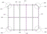
FIG. 3 is a third exemplary steel frame construction of a slab-in-slab floor structure.
FIG. 4 is a perspective view of a fourth exemplary steel frame construction of a slab-in-slab floor construction.
Fig. 5 is a cross-sectional view of an exemplary flat-bed floor structure.
Description of reference numerals:
1-steel frame structure, 100-first transition angle, 110-cross beam, 120-longitudinal beam, 130-connecting steel, 200-second transition angle, 300-third transition angle, 400-fourth transition angle, 111-first cross beam, 112-second cross beam, 121-first longitudinal beam, 122-second longitudinal beam, 131-first connecting steel, 132-second connecting steel, 133-third connecting steel, 134-fourth connecting steel, 140-sandalwood bar, 141-longitudinal purlin first cantilever, 142-longitudinal purlin second cantilever, 150-transverse sandalwood bar, 151-transverse purlin first cantilever, 152-transverse purlin second cantilever, 2-fine stone concrete layer, 3-steel mesh, 4-steel wire mesh, 5-protective layer, 11-C30 fine stone concrete layer, 12-foaming cement.
Detailed Description
Reference will now be made in detail to various exemplary embodiments of the invention, the detailed description should not be construed as limiting the invention but as a more detailed description of certain aspects, features and embodiments of the invention.
It is to be understood that the terminology used herein is for the purpose of describing particular embodiments only and is not intended to be limiting of the invention. Further, for numerical ranges in this disclosure, it is understood that the upper and lower limits of the range, and each intervening value therebetween, is specifically disclosed. Every smaller range between any stated value or intervening value in a stated range and any other stated or intervening value in a stated range is encompassed within the invention. The upper and lower limits of these smaller ranges may independently be included or excluded in the range.
Unless defined otherwise, all technical and scientific terms used herein have the same meaning as commonly understood by one of ordinary skill in the art to which this invention belongs. Although only preferred methods and materials are described herein, any methods and materials similar or equivalent to those described herein can be used in the practice or testing of the present invention. All documents mentioned in this specification are incorporated by reference herein for the purpose of disclosing and describing the methods and/or materials associated with the documents. In case of conflict with any incorporated document, the present specification will control. Unless otherwise indicated, "%" is percent by weight.
The term "slab-in-slab floor structure" according to the present invention refers to prefabricated elements for assembling large buildings, being modular structures that can be used and transported separately, unlike buildings and parts thereof. Preferably, one floor panel of the invention constitutes a horizontal surface.
The term "fixedly connected" in the present invention includes a fixed connection in a detachable manner or a fixed connection in a non-detachable manner. The fixed connection in a detachable manner includes a bolt connection and the like. The non-detachable fixed connection includes welding and the like.
[ Board frame integrated floor panel structure ]
In a first aspect of the present invention, a slab-in-slab floor slab structure is provided, which comprises steel frame structures and a concrete layer filled between the steel frame structures. The respective configurations are described in detail below.
Steel frame structure
The steel frame structure is a framework arranged in a floor panel in the horizontal direction, and is different from a common steel frame structure of the floor panel. The steel frame structure of the invention can comprise one transfer angle, two transfer angles, three transfer angles, four transfer angles and even more than four transfer angles.
Switching angle
The transfer angle of the invention has the following structure: the crossbeam and the longeron weld in same one side of connecting the steel with 45 degrees contained angles respectively to make crossbeam and longeron vertical setting and crossbeam, longeron and connecting steel three be in the coplanar. One end of the connecting steel protrudes from the cross beam at an angle of 45 degrees to form a first flange as one end of the connecting steel, and the plane of the end of the flange is parallel to the cross beam.
In certain embodiments, the length of the first flange perpendicular to the thickness of the beam is the same as or at least more than half the thickness of the corresponding wall. Similarly, the other end of the connecting steel protrudes from the side member at an angle of 45 degrees to form a second flange as the other end of the connecting steel, the end plane of which is parallel to the side member. Preferably, the length of the second flange perpendicular to the thickness of the stringer is the same as or at least more than half the thickness of the corresponding wall. Preferably, the first flange has the same length as the second flange.
In certain embodiments, the welding location of the cross beam to the connecting steel is different from the welding location of the side beam to the same connecting steel. That is, the cross beams and the longitudinal beams which are perpendicular to each other are not connected at the corner joints, but welded integrally through the connecting steel. The design is more favorable for firm connection between the cross beam and the longitudinal beam on one hand, and on the other hand, enough necessary space is reserved for the upright columns at the vertical edges of the wall body, so that firm connection between the upper wall body and the lower wall body through the upright columns is more favorable.
In certain embodiments, the steel frame structure of the present invention is quadrilateral, comprising four transition angles. Specifically, the cross member includes a first cross member and a second cross member. The stringers include a first stringer and a second stringer. The connection steels include a first connection steel, a second connection steel, a third connection steel, and a fourth connection steel. One end of the first cross beam, one end of the first longitudinal beam and the first connecting steel form a first connecting angle. Similarly, the other end of the first cross beam, one end of the second longitudinal beam and the second connecting steel form a second transfer angle. And one end of the second cross beam, the other end of the second longitudinal beam and the third connecting steel form a third transfer angle. And the other end of the second cross beam, the other end of the first longitudinal beam and the fourth connecting steel form a fourth transfer angle.
In the present invention, the lengths of the cross beams and the longitudinal beams are not particularly limited, and can be freely set according to the specifications of the floor panel. The length of the cross beam can be greater than the length of the longitudinal beam, or the length of the cross beam can be less than the length of the longitudinal beam. It is also possible that the length of the cross beams is equal to the length of the longitudinal beams, so that the steel frame structure can be formed substantially square. In the present invention, the cross member is preferably C-shaped steel. More preferably, the invention comprises a first beam and a second beam, wherein the first beam and the second beam are respectively made of C-shaped steel, and the first beam and the second beam are arranged in a manner that grooves of the C-shaped steel are opposite. In the present invention, the longitudinal beam is preferably C-shaped steel. More preferably, the invention comprises a first longitudinal beam and a second longitudinal beam, wherein the first longitudinal beam and the second longitudinal beam are respectively C-shaped steel, and the first longitudinal beam and the second longitudinal beam are arranged in a mode that grooves of the C-shaped steel are opposite. In the present invention, the connection steel is preferably C-shaped steel, and more preferably, the connection steel is disposed in such a manner that the groove of the C-shaped steel faces the inside of the steel frame structure. The length of the connection steel is not particularly limited, and may be, for example, 300-600 mm.
Purlin
In the invention, the steel frame structure optionally further comprises purlins, and the sandal bars can be horizontal purlins or longitudinal purlins. The number of purlins is not particularly limited.
In certain embodiments, the steel frame structure of the present invention further comprises a longitudinal sandal bar connected between the first beam and the second beam, and the longitudinal sandal bar has a first cantilever projecting from the first beam and a second cantilever projecting from the second beam. Preferably, the longitudinal sandal straps are parallel to the longitudinal beams. The number of longitudinal sandal bars is not particularly limited. Generally 2 to 10, preferably 2 to 8, more preferably 2 to 6, etc. The longitudinal sandal wood strips are preferably C-shaped steel. The connection mode of the longitudinal purlines and the cross beams is not particularly limited, and the longitudinal purlines and the cross beams can be connected through welding or can be integrally formed.
In certain embodiments, the steel frame structure of the present invention further comprises a cross-brace connected between the first longitudinal beam and the second longitudinal beam, and the cross-brace has a first cantilevered arm projecting from the first longitudinal beam and a second cantilevered arm projecting from the second longitudinal beam. Preferably, the transverse sandal bars are parallel to the cross beams. The number of transverse sandal straps is not particularly limited. Generally 1 to 10, preferably 1 to 4, e.g. 1, etc. The longitudinal sandal wood strips are preferably C-shaped steel. The connection mode of the longitudinal purlines and the cross beams is not particularly limited, and the longitudinal purlines and the cross beams can be connected through welding or can be integrally formed.
Reinforcing or wire meshes
The steel frame structure of the present invention may optionally further comprise a steel mesh and/or a steel wire mesh.
In certain embodiments, the steel frame structure of the present invention further comprises a rebar grid. Preferably, the mesh reinforcement is welded to one side of the steel frame structure. The reinforcing mesh in the invention is a net structure formed by reinforcing steel bars with larger diameters. The diameter of the steel bar in the steel bar mesh is generally 5mm to 10 mm.
In certain embodiments, the steel frame structure of the present invention further comprises a steel mesh. Preferably the wire mesh is welded to the other side of the steel frame structure opposite the wire mesh. The steel wire mesh in the invention refers to a net structure formed by steel wires with smaller diameter. The diameter of the steel wire is typically 1-4mm, for example 3 mm.
Concrete layer
The concrete layer of the present invention is a structure formed of concrete filled between steel frame structures. The concrete includes C30 fine stone concrete or foamed concrete. Preferably, the concrete layer of the invention comprises layers of different concrete types. For example, comprises a C30 fine stone concrete layer and 400-K600 kg/m3The foamed concrete layer of (1). The thickness of the C30 fine stone concrete layer is generally 15-30mm, preferably 18-25 mm. The thickness of the foamed concrete layer is generally 100-200mm, preferably 120-160 mm.
Protective layer
Optionally, the slab and rack integrated floor panel of the invention further comprises a protective layer. Preferably, the protective layer is a cement mortar protective layer. Further preferably, the protective layer of the present invention further comprises an alkali-resistant fiberglass mesh cloth attached inside. The thickness of the protective layer is generally from 10 to 30mm, preferably from 15 to 25 mm.
Fine sand concrete layer
Optionally, the slab-in-slab floor panel of the present invention further comprises a fine sand concrete layer disposed on the side of the floor panel. The fine sand concrete layer is used for further embedding the steel frame structure, so that the steel frame structure is prevented from being exposed to the environment. The thickness of the fine sand concrete layer is generally 25 to 45mm, preferably 30 to 35 mm.
Facing material layer
Optionally, the slab and slab integrated floor panel of the present invention further comprises a layer of facing material. The finishing material layer is directly used as a part of a prefabricated floor panel structure by prefabricating in a production workshop or the like, thereby reducing the construction amount in the building construction process and greatly improving the assembly level and the construction speed. The facing material layer includes a face brick layer, etc.
[ production method ]
In a second aspect of the present invention, there is provided a method for producing a slab-in-slab floor structure, comprising at least the steps of:
(1) paying off on a mould platform of the production line, and erecting a side mould according to the size of a floor panel;
(2) optionally, reversely paving the facing material on the bottom die by using a reverse beating process, and spraying polymer mortar with the thickness of 3-5mm on the bottom surface of the facing material;
(3) and (3) welding a steel mesh above the integrally welded steel frame structure, welding a steel mesh on the bottom surface of the steel frame structure, hoisting the steel frame structure, putting the steel frame structure into a formwork, and pouring concrete in the formwork. The concrete here may be foamed cement;
(4) and applying cement mortar on the surface of the concrete, pressing the cement mortar into the grid cloth, removing the side die, and performing steam curing to obtain the slab-frame integrated floor panel structure.
It is known to those skilled in the art that the production method of the present invention may include other steps in addition to the above steps. These other steps may be between the above steps (1) to (4), or may be before the above step (1) or after the step (4).
Example 1
Fig. 1 is a structural diagram of an exemplary steel frame of a slab-in-slab floor structure. As shown in fig. 1, in the present embodiment, the steel frame structure 1 has an adapter angle 100. The transition angle 100 is formed by a transverse beam 110, a longitudinal beam 120 and a connecting steel 130. The cross beam 110 and the longitudinal beam 120 are welded to the same side of the connection steel 130 at an included angle of 45 degrees, respectively, so that the cross beam 110 and the longitudinal beam 120 are vertically disposed. The cross beam 110, the longitudinal beam 120 and the connection steel 130 are in the same plane. One end of the connection steel 130 protrudes from the beam 110, and the end plane is parallel to the beam 110. The other end of the connecting steel 130 protrudes from the longitudinal beam 120, and the plane of the end is parallel to the longitudinal beam 120. The welding position of the cross beam 110 and the connecting steel 130 is kept at a certain distance from the welding position of the longitudinal beam 120 and the connecting steel 130. In fig. 1, one end of the connecting steel protrudes from the cross beam at an angle of 45 degrees, thereby forming a first flange. The other end of the connecting steel protrudes from the longitudinal beam at an included angle of 45 degrees, thereby forming a second flange.
Fig. 2 is another exemplary steel frame structure diagram of a slab-in-slab floor structure. As shown in fig. 2, the steel frame structure includes two transition angles. Namely a first transition angle 100 and a second transition angle 200.
Fig. 3 is a third exemplary steel frame structure diagram of a slab-in-slab floor structure. As shown in fig. 3, the steel frame structure includes four transition angles. Namely a first transition angle 100, a second transition angle 200, a third transition angle 300 and a fourth transition angle 400.
In fig. 3, the cross beam comprises a first cross beam 111 and a second cross beam 112, the longitudinal beams comprise a first longitudinal beam 121 and a second longitudinal beam 122, and the connecting steels comprise a first connecting steel 131, a second connecting steel 132, a third connecting steel 133 and a fourth connecting steel 134. One end of the first cross member 111, one end of the first longitudinal member 121, and the first connecting steel 131 constitute a first corner 100. The other end of the first cross beam 111, one end of the second longitudinal beam 122, and the second connecting steel 132 form a second transfer angle 200. One end of the second cross beam 112, the other end of the second longitudinal beam 122, and the third connecting steel 133 form a third transfer angle 300. The other end of the second cross beam 112, the other end of the first longitudinal beam 121, and the fourth connecting steel 134 form a fourth transfer angle 400.
Also shown in fig. 3 is that the steel frame structure further includes 4 longitudinal purlins 140, each longitudinal purlin 140 being connected in parallel between the first cross beam 111 and the second cross beam 112. The longitudinal sandal straps 140 have a first cantilever 141 protruding from the first beam 111 and a second cantilever 142 protruding from the second beam 112. The floor panels can be firmly fixed to the wall bodies on both sides by the first cantilever 141 and the second cantilever 142, and the two adjacent floor panels in the horizontal direction can be fixed by the connection between the first cantilever 141 and the second cantilever 142 of other floor panels. In addition, fig. 3 also shows that the steel frame structure further includes 1 horizontal sandal bar 150, which is fixed between the first longitudinal beam 121 and the second longitudinal beam 122 in parallel.
FIG. 4 is a perspective view of a fourth exemplary steel frame construction of a slab-in-slab floor construction. As shown in fig. 4, in the steel frame structure, the horizontal sandal bar 150 has a first suspension arm 151 protruding from the first longitudinal beam 121 and a second suspension arm 152 protruding from the second longitudinal beam 122. Crossbeam, longeron, indulge wingceltis strip, horizontal wingceltis strip and connecting steel are C shaped steel respectively, and the C shaped steel recess of first crossbeam 111 sets up with the C shaped steel recess of second crossbeam 112 relatively, and the C shaped steel recess of first longeron 121 sets up with the C shaped steel recess of second longeron 122 relatively, and the C shaped steel recess of connecting steel sets up with the mode towards steel frame construction is inside. Otherwise, the remaining structure is the same as the third exemplary steel frame structure shown in fig. 3.
Fig. 5 is a cross-sectional view of an exemplary flat-bed floor structure. As shown in fig. 5, the floor slab comprises, from top to bottom, a fine stone concrete layer 2, a steel mesh 3, a steel frame structure 1, a steel wire mesh 4 and a cement mortar protective layer 5 (an alkali-resistant glass fiber mesh cloth is attached inside). Wherein the fine stone concrete layer 2 has the thickness of 30mm C30, and the specification of the steel bar is 6@200 multiplied by 200. The diameter of the steel wire is 3@50 x 50. The thickness of the steel frame structure 1 is 160 mm. The thickness of the cement mortar protective layer 5 is 20 mm. The lower layer inside the steel frame structure 1 is filled with 140mm of 500kg/m3 Foamed cement 12, on which 20mm thick C30 fine-grained concrete 11 is filled.
It will be apparent to those skilled in the art that various modifications and variations can be made in the specific embodiments of the present disclosure without departing from the scope or spirit of the disclosure. Other embodiments will be apparent to those skilled in the art from consideration of the specification. The specification and examples are exemplary only.
Claims (10)
1. The utility model provides a floor panel structure is unified to board frame which characterized in that, include steel frame construction and fill in concrete layer between the steel frame construction, wherein:
the steel frame structure comprises a transfer angle formed by a cross beam, a longitudinal beam and connecting steel, wherein in the transfer angle, the cross beam and the longitudinal beam are respectively welded on the same side of the connecting steel at an included angle of 45 degrees, so that the cross beam and the longitudinal beam are vertically arranged, the cross beam, the longitudinal beam and the connecting steel are positioned in the same plane, one tail end of the connecting steel protrudes out of the cross beam, the tail end plane of the connecting steel is parallel to the cross beam, and the other tail end of the connecting steel protrudes out of the longitudinal beam, the tail end plane of the connecting steel is parallel to the longitudinal beam.
2. A slab-in-slab floor structure as claimed in claim 1 wherein the welding locations of said cross beams to said connecting steel are different from the welding locations of said longitudinal beams to said connecting steel.
3. A slab-in-slab floor structure according to claim 2, wherein the cross beams comprise first and second cross beams, the longitudinal beams comprise first and second longitudinal beams, and the connecting steels comprise first, second, third and fourth connecting steels;
the one end of first crossbeam, the one end of first longeron and first connecting steel constitutes first switching angle, the other end of first crossbeam, the one end of second longeron and second connecting steel constitutes the second switching angle, the one end of second crossbeam, the other end of second longeron and third connecting steel constitutes the third switching angle, the other end of second crossbeam, the other end of first longeron and fourth connecting steel constitute the fourth switching angle.
4. The slab-in-slab floor structure of claim 3, further comprising a longitudinal sandalwood strip connected between the first beam and the second beam, the longitudinal sandalwood strip having a first cantilevered arm protruding from the first beam and a second cantilevered arm protruding from the second beam.
5. The slab-in-slab floor structure of claim 4, further comprising a transverse purlin connected between the first longitudinal beam and the second longitudinal beam, optionally the transverse purlin having a first cantilever projecting from the first longitudinal beam and a second cantilever projecting from the second longitudinal beam.
6. The slab-in-one floor structure as claimed in claim 5, wherein the cross beams, the longitudinal bars and the transverse bars are C-shaped steel, respectively, and the C-shaped steel grooves of the first cross beam are opposite to the C-shaped steel grooves of the second cross beam, and the C-shaped steel grooves of the first longitudinal beam are opposite to the C-shaped steel grooves of the second longitudinal beam.
7. A slab-in-slab floor structure according to claim 6 further comprising a mesh reinforcement welded to one side of the steel frame structure or further comprising a steel mesh welded to the other side of the steel frame structure.
8. The slab-in-slab floor structure according to claim 1, wherein a cement mortar protective layer is provided on one side of the steel-frame structure, a fine sand concrete layer is provided on the other side of the steel-frame structure, and optionally, a facing material layer is further provided on the side of the fine sand concrete layer.
9. A method of producing a slab-in-slab floor structure according to any of claims 1-8, comprising the steps of:
(1) paying off on a mould platform of the production line, and erecting a side mould according to the size of a floor panel;
(2) optionally, reversely paving the facing material on the bottom die by using a reverse beating process, and spraying polymer mortar with the thickness of 3-5mm on the bottom surface of the facing material;
(3) welding a steel mesh above the integrally welded steel frame structure, welding a steel mesh on the bottom surface of the steel frame structure, hoisting the steel frame structure, placing the steel frame structure into a formwork, and pouring concrete in the formwork;
(4) and applying cement mortar on the surface of the concrete, pressing the cement mortar into the grid cloth, removing the side die, and performing steam curing to obtain the slab-frame integrated floor panel structure.
10. The method for producing a slab-in-slab floor structure according to claim 9, wherein in the step (3), C30 fine stone concrete is poured first, and foamed concrete is further poured after the compaction.
Priority Applications (1)
| Application Number | Priority Date | Filing Date | Title |
|---|---|---|---|
| CN201910414477.7A CN110130552B (en) | 2019-05-17 | 2019-05-17 | Board and frame integrated floor panel structure and production method thereof |
Applications Claiming Priority (1)
| Application Number | Priority Date | Filing Date | Title |
|---|---|---|---|
| CN201910414477.7A CN110130552B (en) | 2019-05-17 | 2019-05-17 | Board and frame integrated floor panel structure and production method thereof |
Publications (2)
| Publication Number | Publication Date |
|---|---|
| CN110130552A CN110130552A (en) | 2019-08-16 |
| CN110130552B true CN110130552B (en) | 2020-04-21 |
Family
ID=67575119
Family Applications (1)
| Application Number | Title | Priority Date | Filing Date |
|---|---|---|---|
| CN201910414477.7A Active CN110130552B (en) | 2019-05-17 | 2019-05-17 | Board and frame integrated floor panel structure and production method thereof |
Country Status (1)
| Country | Link |
|---|---|
| CN (1) | CN110130552B (en) |
Family Cites Families (6)
| Publication number | Priority date | Publication date | Assignee | Title |
|---|---|---|---|---|
| GB1150920A (en) * | 1966-11-25 | 1969-05-07 | Terrapin Ltd | Improvements in or relating to Building Structures |
| CN101260736B (en) * | 2008-04-16 | 2010-11-03 | 马永乐 | Tools-type barrel formwork and following platform whole set device |
| CN202148598U (en) * | 2011-06-01 | 2012-02-22 | 永升建设集团有限公司 | 45-degree inclined large cantilever reinforced concrete structure |
| CN102979174B (en) * | 2012-11-26 | 2015-06-17 | 北京工业大学 | Multi-story high-rise assembled steel structure frame system |
| CN107190905A (en) * | 2017-07-14 | 2017-09-22 | 北京善筑科技股份有限公司 | Light gauge cold-formed steel shape integration beam slab and preparation method thereof |
| CN208310219U (en) * | 2018-04-18 | 2019-01-01 | 沈阳建筑大学 | Board bottom has assembled composite beam-plate connection support device of height difference |
-
2019
- 2019-05-17 CN CN201910414477.7A patent/CN110130552B/en active Active
Also Published As
| Publication number | Publication date |
|---|---|
| CN110130552A (en) | 2019-08-16 |
Similar Documents
| Publication | Publication Date | Title |
|---|---|---|
| JP5830195B2 (en) | How to assemble a truss, suspend a formwork, and manufacture a ferrocement slab on site | |
| CN114108917B (en) | Height-adjustable assembly type composite floor slab construction method | |
| CN207878747U (en) | A kind of laminated floor slab prefabricated board | |
| CN101787760B (en) | Steel bar concrete precast floor slab | |
| CN102071746A (en) | T-shaped connecting node for superposed external wall and prefabricated internal wall of shear wall structure | |
| CN118273462A (en) | Concrete module integrated with prefabricated shear wall and assembly method | |
| CN207295977U (en) | EPS module reinforced concrete frame structure space modules | |
| CN113719008B (en) | A construction process for steel mesh truss hollow nest core board | |
| CN215053993U (en) | Prefabricated steel-concrete beam, column and floor combined house | |
| CN115749129A (en) | Prefabricated lattice type steel reinforced concrete combined beam, column and shear wall component | |
| CN113047632A (en) | Prefabricated steel-concrete beam, column and floor combined building construction method | |
| CN111101628B (en) | A kind of FRP sheet connecting structure and method of precast concrete beam-slab system | |
| CN110130552B (en) | Board and frame integrated floor panel structure and production method thereof | |
| CN110130554B (en) | Floor panel structure integrating sound insulation plate frame and production method | |
| CN210164057U (en) | Assembled steel and concrete flat wall column composite structure | |
| CN119641016A (en) | Assembled multi-layer light concrete sandwich wallboard structure system and construction method | |
| CN111851804A (en) | A prefabricated formwork-free structural body formwork and a cast-in-place formwork-free structural body | |
| CN111364642A (en) | A prefabricated energy-consuming shear wall system and its construction method | |
| CN216239245U (en) | Hollow nest core plate of steel mesh truss | |
| CN112282164B (en) | Light composite floor slab structure and construction method thereof | |
| CN206279676U (en) | Prefabricated assembly interlock formula light floor | |
| CN212453063U (en) | Assembly and pouring integrated shear wall structure building system | |
| CN212248770U (en) | A L type self preservation temperature shear force wall prefabricated plate for prefabricated construction corner | |
| CN116145875A (en) | A new type of reinforced truss concrete laminated hollow floor and its implementation method | |
| CN110130556B (en) | Waterproof board frame and one-floor board structure and production method thereof |
Legal Events
| Date | Code | Title | Description |
|---|---|---|---|
| PB01 | Publication | ||
| PB01 | Publication | ||
| SE01 | Entry into force of request for substantive examination | ||
| SE01 | Entry into force of request for substantive examination | ||
| CB02 | Change of applicant information | ||
| CB02 | Change of applicant information |
Address after: 253000 500 meters east of shengjinliu community, Beijing Tianjin Hebei Collaborative Development Industrial Cooperation Zone, Lingcheng District, Dezhou City, Shandong Province Applicant after: Shandong Lianxing Luxia Architectural Technology Co., Ltd. Address before: 253034 Shengjin-Liu Community, Decheng District, Dezhou City, Shandong Province, 500 meters east of Beijing-Tianjin-Hebei Cooperative Development Industrial Cooperation Zone Applicant before: Shandong Lianxing Luxia Architectural Technology Co., Ltd. |
|
| GR01 | Patent grant | ||
| GR01 | Patent grant |