CN110114517B - Method for producing thin functional coatings on light alloys - Google Patents
Method for producing thin functional coatings on light alloys Download PDFInfo
- Publication number
- CN110114517B CN110114517B CN201780049650.7A CN201780049650A CN110114517B CN 110114517 B CN110114517 B CN 110114517B CN 201780049650 A CN201780049650 A CN 201780049650A CN 110114517 B CN110114517 B CN 110114517B
- Authority
- CN
- China
- Prior art keywords
- anodized
- plating
- layer
- thin
- bath
- Prior art date
- Legal status (The legal status is an assumption and is not a legal conclusion. Google has not performed a legal analysis and makes no representation as to the accuracy of the status listed.)
- Active
Links
Images


Classifications
-
- C—CHEMISTRY; METALLURGY
- C25—ELECTROLYTIC OR ELECTROPHORETIC PROCESSES; APPARATUS THEREFOR
- C25D—PROCESSES FOR THE ELECTROLYTIC OR ELECTROPHORETIC PRODUCTION OF COATINGS; ELECTROFORMING; APPARATUS THEREFOR
- C25D11/00—Electrolytic coating by surface reaction, i.e. forming conversion layers
- C25D11/02—Anodisation
- C25D11/04—Anodisation of aluminium or alloys based thereon
- C25D11/18—After-treatment, e.g. pore-sealing
- C25D11/20—Electrolytic after-treatment
-
- C—CHEMISTRY; METALLURGY
- C25—ELECTROLYTIC OR ELECTROPHORETIC PROCESSES; APPARATUS THEREFOR
- C25D—PROCESSES FOR THE ELECTROLYTIC OR ELECTROPHORETIC PRODUCTION OF COATINGS; ELECTROFORMING; APPARATUS THEREFOR
- C25D11/00—Electrolytic coating by surface reaction, i.e. forming conversion layers
- C25D11/02—Anodisation
- C25D11/04—Anodisation of aluminium or alloys based thereon
- C25D11/06—Anodisation of aluminium or alloys based thereon characterised by the electrolytes used
- C25D11/08—Anodisation of aluminium or alloys based thereon characterised by the electrolytes used containing inorganic acids
-
- C—CHEMISTRY; METALLURGY
- C25—ELECTROLYTIC OR ELECTROPHORETIC PROCESSES; APPARATUS THEREFOR
- C25D—PROCESSES FOR THE ELECTROLYTIC OR ELECTROPHORETIC PRODUCTION OF COATINGS; ELECTROFORMING; APPARATUS THEREFOR
- C25D11/00—Electrolytic coating by surface reaction, i.e. forming conversion layers
- C25D11/02—Anodisation
- C25D11/04—Anodisation of aluminium or alloys based thereon
- C25D11/16—Pretreatment, e.g. desmutting
-
- C—CHEMISTRY; METALLURGY
- C25—ELECTROLYTIC OR ELECTROPHORETIC PROCESSES; APPARATUS THEREFOR
- C25D—PROCESSES FOR THE ELECTROLYTIC OR ELECTROPHORETIC PRODUCTION OF COATINGS; ELECTROFORMING; APPARATUS THEREFOR
- C25D11/00—Electrolytic coating by surface reaction, i.e. forming conversion layers
- C25D11/02—Anodisation
- C25D11/04—Anodisation of aluminium or alloys based thereon
- C25D11/18—After-treatment, e.g. pore-sealing
- C25D11/24—Chemical after-treatment
-
- C—CHEMISTRY; METALLURGY
- C25—ELECTROLYTIC OR ELECTROPHORETIC PROCESSES; APPARATUS THEREFOR
- C25D—PROCESSES FOR THE ELECTROLYTIC OR ELECTROPHORETIC PRODUCTION OF COATINGS; ELECTROFORMING; APPARATUS THEREFOR
- C25D11/00—Electrolytic coating by surface reaction, i.e. forming conversion layers
- C25D11/02—Anodisation
- C25D11/26—Anodisation of refractory metals or alloys based thereon
-
- C—CHEMISTRY; METALLURGY
- C25—ELECTROLYTIC OR ELECTROPHORETIC PROCESSES; APPARATUS THEREFOR
- C25D—PROCESSES FOR THE ELECTROLYTIC OR ELECTROPHORETIC PRODUCTION OF COATINGS; ELECTROFORMING; APPARATUS THEREFOR
- C25D11/00—Electrolytic coating by surface reaction, i.e. forming conversion layers
- C25D11/02—Anodisation
- C25D11/30—Anodisation of magnesium or alloys based thereon
-
- C—CHEMISTRY; METALLURGY
- C25—ELECTROLYTIC OR ELECTROPHORETIC PROCESSES; APPARATUS THEREFOR
- C25D—PROCESSES FOR THE ELECTROLYTIC OR ELECTROPHORETIC PRODUCTION OF COATINGS; ELECTROFORMING; APPARATUS THEREFOR
- C25D13/00—Electrophoretic coating characterised by the process
- C25D13/20—Pretreatment
-
- C—CHEMISTRY; METALLURGY
- C25—ELECTROLYTIC OR ELECTROPHORETIC PROCESSES; APPARATUS THEREFOR
- C25D—PROCESSES FOR THE ELECTROLYTIC OR ELECTROPHORETIC PRODUCTION OF COATINGS; ELECTROFORMING; APPARATUS THEREFOR
- C25D21/00—Processes for servicing or operating cells for electrolytic coating
- C25D21/08—Rinsing
-
- C—CHEMISTRY; METALLURGY
- C25—ELECTROLYTIC OR ELECTROPHORETIC PROCESSES; APPARATUS THEREFOR
- C25D—PROCESSES FOR THE ELECTROLYTIC OR ELECTROPHORETIC PRODUCTION OF COATINGS; ELECTROFORMING; APPARATUS THEREFOR
- C25D5/00—Electroplating characterised by the process; Pretreatment or after-treatment of workpieces
- C25D5/18—Electroplating using modulated, pulsed or reversing current
-
- C—CHEMISTRY; METALLURGY
- C25—ELECTROLYTIC OR ELECTROPHORETIC PROCESSES; APPARATUS THEREFOR
- C25D—PROCESSES FOR THE ELECTROLYTIC OR ELECTROPHORETIC PRODUCTION OF COATINGS; ELECTROFORMING; APPARATUS THEREFOR
- C25D5/00—Electroplating characterised by the process; Pretreatment or after-treatment of workpieces
- C25D5/34—Pretreatment of metallic surfaces to be electroplated
- C25D5/38—Pretreatment of metallic surfaces to be electroplated of refractory metals or nickel
-
- C—CHEMISTRY; METALLURGY
- C25—ELECTROLYTIC OR ELECTROPHORETIC PROCESSES; APPARATUS THEREFOR
- C25D—PROCESSES FOR THE ELECTROLYTIC OR ELECTROPHORETIC PRODUCTION OF COATINGS; ELECTROFORMING; APPARATUS THEREFOR
- C25D5/00—Electroplating characterised by the process; Pretreatment or after-treatment of workpieces
- C25D5/34—Pretreatment of metallic surfaces to be electroplated
- C25D5/42—Pretreatment of metallic surfaces to be electroplated of light metals
- C25D5/44—Aluminium
-
- C—CHEMISTRY; METALLURGY
- C25—ELECTROLYTIC OR ELECTROPHORETIC PROCESSES; APPARATUS THEREFOR
- C25D—PROCESSES FOR THE ELECTROLYTIC OR ELECTROPHORETIC PRODUCTION OF COATINGS; ELECTROFORMING; APPARATUS THEREFOR
- C25D5/00—Electroplating characterised by the process; Pretreatment or after-treatment of workpieces
- C25D5/60—Electroplating characterised by the structure or texture of the layers
- C25D5/605—Surface topography of the layers, e.g. rough, dendritic or nodular layers
- C25D5/611—Smooth layers
-
- C—CHEMISTRY; METALLURGY
- C25—ELECTROLYTIC OR ELECTROPHORETIC PROCESSES; APPARATUS THEREFOR
- C25D—PROCESSES FOR THE ELECTROLYTIC OR ELECTROPHORETIC PRODUCTION OF COATINGS; ELECTROFORMING; APPARATUS THEREFOR
- C25D5/00—Electroplating characterised by the process; Pretreatment or after-treatment of workpieces
- C25D5/627—Electroplating characterised by the visual appearance of the layers, e.g. colour, brightness or mat appearance
-
- C—CHEMISTRY; METALLURGY
- C25—ELECTROLYTIC OR ELECTROPHORETIC PROCESSES; APPARATUS THEREFOR
- C25D—PROCESSES FOR THE ELECTROLYTIC OR ELECTROPHORETIC PRODUCTION OF COATINGS; ELECTROFORMING; APPARATUS THEREFOR
- C25D11/00—Electrolytic coating by surface reaction, i.e. forming conversion layers
- C25D11/02—Anodisation
- C25D11/04—Anodisation of aluminium or alloys based thereon
- C25D11/06—Anodisation of aluminium or alloys based thereon characterised by the electrolytes used
- C25D11/10—Anodisation of aluminium or alloys based thereon characterised by the electrolytes used containing organic acids
-
- C—CHEMISTRY; METALLURGY
- C25—ELECTROLYTIC OR ELECTROPHORETIC PROCESSES; APPARATUS THEREFOR
- C25D—PROCESSES FOR THE ELECTROLYTIC OR ELECTROPHORETIC PRODUCTION OF COATINGS; ELECTROFORMING; APPARATUS THEREFOR
- C25D5/00—Electroplating characterised by the process; Pretreatment or after-treatment of workpieces
- C25D5/10—Electroplating with more than one layer of the same or of different metals
- C25D5/12—Electroplating with more than one layer of the same or of different metals at least one layer being of nickel or chromium
- C25D5/14—Electroplating with more than one layer of the same or of different metals at least one layer being of nickel or chromium two or more layers being of nickel or chromium, e.g. duplex or triplex layers
Abstract
In an exemplary embodiment, a method for manufacturing a thin film coating is provided. The method includes pretreating a substrate, placing the substrate in a bath including at least phosphoric acid and sulfuric acid to produce a thin anodized layer, rinsing the thin anodized layer in a solution, plating a surface of the thin anodized layer in an electrodeposition bath according to a plating current profile for a predetermined period of time, and increasing the plating current to a recommended bath plating current to produce a thin film coating having a desired initial coating thickness.
Description
Background
Aluminum and its alloys are widely used materials for automotive, structural and aerospace applications, but many alloys suffer from environmental degradation due to corrosion because there is no suitable functional coating. Many methods have been developed to protect aluminum surfaces, including anodization, plating, and chemical coatings. However, in order to effectively protect the aluminum surface, a thick plating or anodizing film is required. Alternatively, a thin film of an environmentally hazardous material such as cadmium or hexavalent chromium is required.
Anodization is a well-known method of protecting aluminum and other light metal surfaces. Different applications of anodized surfaces may utilize thick films where high protection is required or thin films for more decorative applications. In thick film or hard anodising, an oxide surface of 25-150 microns thickness is formed. The surface is typically sealed in a process that includes dyeing. Additional protective coatings may then be applied to the surface. Two patents US 4,431,707 and US 4,624,752 describe methods of further treating hard anodized surfaces so that they can be plated. Both methods include a chemical etching stage to produce a conductive surface layer that can be applied and a plating layer electrodeposited on the surface.
Thin film anodized surfaces are typically between 0.5 and 25 microns. As with hard anodization, these surfaces are typically sealed to provide environmental protection. The advantage of a thin anodized surface is that sufficient electrical conductivity is retained between the substrates by the anodized pores so that a functional film can be electrodeposited directly on the anodized surface. U.S. Pat. nos. 3,915,811 and 3,943,039 describe further processing of anodized films and methods of electrodeposition, particularly nickel coatings, on such films. These patents describe different baths and methods for anodization, while various electrodeposition methods have been proposed to provide a functional surface. Both of these patents relate to aluminum alloy sub-equipment of particular importance to the automotive bumper automotive industry and generally involve electrodeposition of one or more thick layers to achieve corrosion resistance and decorative aspects of these applications. More specifically, these patents do not teach the methods disclosed in the present application to ensure complete filling of the anodized pores and to allow the thin film electrodeposited surface to achieve good corrosion protection and other functional properties.
Electrodeposition on aluminum is also well known and generally involves the application of a very thin layer of zinc to a surface using a zincate process followed by the application of one or more plating coatings to the surface. The zincate process is inherently problematic and is necessary to obtain good electrodeposited coatings, so double and triple zincate steps are often required to obtain acceptable results. In many cases, the first plating layer is a thick (40-50 microns) electroless Ni-P coating or semi-bright electrolytic nickel to provide corrosion protection. The first layer is followed by a functional or decorative surface layer, which may be bright nickel. In one application, the surface coating is electrodeposited Zn-Ni. Ni-P/Zn-Ni coating systems have been developed to replace the environmentally hazardous chromate-passivated cadmium for electrical connector housings. However, this method is expensive in both time and material, and is not as effective as the coating it is designed to replace.
Anodized films are also used as templates for producing nanowires for sensors, as described in US 2009/0242416. Although this patent teaches plating in the pores of the anodized surface, it does not teach controlling the current to ensure complete filling of the nanopores and achieve interlocking between the nanowires and the pores. It also does not teach increasing the current as the pores are filled to ensure complete coverage of the anodized film.
Accordingly, there is a need in the art for a method of coating aluminum and other light metal surfaces with a flash coating that provides protection against corrosion and other functional attributes.
Disclosure of Invention
According to aspects illustrated herein, a method of making a thin film coating is provided. One disclosed feature of an embodiment is a method including pretreating a substrate, placing the substrate in a bath comprising at least phosphoric acid and sulfuric acid to produce a thin anodized layer, rinsing the thin anodized layer in a solution, plating a surface of the thin anodized layer in an electrodeposition bath according to a plating current profile for a predetermined period of time, and increasing the plating current to a recommended bath plating current to produce a thin film coating having a desired initial coating thickness.
Drawings
FIG. 1 is a Scanning Electron Microscope (SEM) image of an anodized surface;
FIG. 2 is an SEM of anodized defects;
FIG. 3 is an SEM of a cross section of a filled anodized layer;
FIG. 4 is an image of a unique modality;
FIG. 5 is an image of an example effect of hemispherical surface morphology;
FIG. 6 is an image of a cross section of a hybrid SB/bright Ni coating;
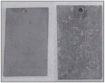
FIG. 7 is an image of the adhesion test of a hybrid SB/Bright Ni coating;
FIG. 8 is an image of an image before and after a copper accelerated acetate spray (CASS) test;
FIG. 9 is an image of a dual hybrid coating with a Zn-Ni surface;
FIG. 10 is an image of adhesion test results for a dual hybrid coating;
FIG. 11 is an image of the results before and after CASS testing of a dual hybrid Zn-Ni coating;
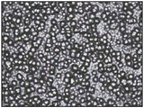
FIG. 12 is an image of the surface morphology of a hybrid black nickel coating;
FIG. 13 is an image of UV-visible-infrared light absorption properties;
FIG. 14 is an image of wear resistance under a 1N load;
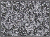
FIG. 15 is an image of the surface morphology of a hybrid black nickel coating;
FIG. 16 is an image of comparative wear traces of a hybrid coating and a conventional coating;
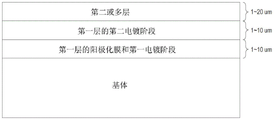
FIG. 17 is an image of example thicknesses of various layers; and
FIG. 18 is a flow chart of an exemplary method for producing a thin film coating.
Detailed Description
The embodiments described herein provide an improved method of forming a flash coating on aluminum or light metal alloys. The method comprises one or more of the following steps: degreasing the alloy matrix; electropolishing the substrate; activating the surface; anodizing a 1-10 micron film on a substrate in an anodizing bath comprising substantially phosphoric acid; optionally activating the anodized surface in a solution containing hydrofluoric acid to completely dissolve the anodized surface end caps; electrodepositing a first coating (including an anodized film) of between 1 and 20 microns using a voltage profile for electrodeposition to ensure that the anodized pores are completely filled and sealed and form a surface upon which additional coatings can be deposited; optionally, a sealing phase using a nickel acetate bath may follow the first plating step to seal any anodized pores that are not completely filled by the first plating step; and optionally depositing a second or more functional coatings of 0 to 20 microns on the first layer. The total average thickness of the hybrid coating may be about 2-40 microns.
Fig. 18 illustrates an exemplary method 1800 for fabricating a thin film coating. In one embodiment, the method 1800 may be performed by various devices or tools in a processing facility under the control of a processor or controller.
At block 1802, method 1800 begins. At block 1804, the method 1800 may pre-process the substrate. In one embodiment, the substrate may be aluminum, titanium, or magnesium.
Pretreatment may include degreasing the substrate in an alkaline bath, roughening the substrate in a solution of polyethylene glycol, sulfuric acid, and hydrofluoric acid or other similar solutions, and etching the substrate in a nitric acid solution. An example of a solution may be a commercial aluminum surface pretreatment known as Probright AL. The solution that roughens the substrate can clean the substrate surface as the substrate is etched.
One example of pretreatment may include first degreasing the substrate in a commercial solution (e.g., actvax from MacDermid). The degreasing step is followed by a degreasing step in the presence of a hydrogen-containing gas comprising, by volume, from 70 to 85 3 PO 4 、HF、H 2 SO 4 And glycerol in a bath for rinsing and electropolishing. Rinsing the substrate prior to anodization has the effect of eliminating impurities on the surface, which can lead to defects in the thin anodization layer. These impurities include insoluble alloying elements in the matrix. The electropolishing bath is maintained at a temperature of 70-80 degrees celsius (c) at a voltage (V) of about 12V. The electropolishing step provides a uniform surface of the substrate with minimal surface alloying elements, which helps to achieve a uniform anodization layer. The electropolished substrate is then rinsed in deionized water prior to the activation and anodization steps.
In one embodiment, the substrate may optionally be activated prior to anodization. The activation step may provide some benefits to certain alloys. One example of an activation step may include inclusion of HNO that is typically 40% by volume but is effective between 20 and 50V% 3 And activating the surface in a bath of HF between 1 and 10 milliliters per liter (mL/L). The bath is maintained at a temperature of 20 ℃ to 25 ℃, and the substrate is immersed and stirred approximately once per second for 20 to 40 seconds.
Another example of an activation step may include a short anodization step, also referred to as "patterning", lasting 1 minute or less. Patterning can improve the quality of the anodized film. One example includes removing the developed anodized layer in a sodium hydroxide bath, rinsing, and then anodizing again after the anodization process described herein.
At block 1806, the method 1800 places the substrate in a bath including at least phosphoric acid and sulfuric acid to create a thin anodized layer. In one embodiment, the electrical parameters and bath composition of the anodization step are carefully controlled to ensure that the anodized surface contains a uniform high density distribution of thin-walled pores having diameters between 50 and 70 nanometers (nm), as shown in fig. 1. The anodizing bath, which contains mainly phosphoric acid and a small amount of sulfuric acid and a small amount of oxalic acid, is operated at room temperature (20 c to 25 c). The bath composition is selected from H 3 PO 4 280-600g/L (g/L), H 2 SO 4 1-15g/L and 1-10g/L of HOOCCOOH. A voltage between 30V and 60V and 2 amperes per square decimeter (A/dm) 2 ) Constant voltage anodization at the maximum current density of (a) provides the best pore distribution and density. The anodized film in the present disclosure has a thickness of between 1 and 10 micrometers; however, the thickness may also be between 1 and 5 micrometers. In one embodiment, the thickness may be between 1 and 2 microns. Anodizing for 10 minutes under the above conditions produced an anodized film of about 2.5 micrometers. The thin anodized layer becomes a key layer for the hybrid coating system, allowing the subsequently deposited layer to interlock strongly with the layer to provide adhesion over conventional plating solutions.
In the anodizing step, when anodizing a thin film, a problem to be dealt with is that some alloying elements (e.g., silicon and iron) are not completely dissolved from the substrate. The electropolishing and activation steps reduce but do not eliminate the presence of these elements from the surface prior to anodization. The presence of these elements may cause anodization defects as shown in the SEM image of fig. 2. These defects may create defects in the first electrodeposited layer that either do not completely cover the anodized layer or do not completely interlock with the anodized layer, resulting in low adhesion and potential corrosion pathways. The selection of low temperature and low constant voltage anodization minimizes the creation of these defects. The optional sealing step may eliminate potential corrosion paths.
At block 1808, the method 1800 rinses the anodized layer in a solution. In one embodiment, rinsing may be used to completely dissolve the anodized end cap at the bottom of the well. The solution may be a bath containing 0.5-5mL/L HF. The anodized substrate to be treated was immersed in the rinsing bath for about 30 seconds with agitation about once per second.
At block 1810, the method 1800 plates the surface of the anodized layer in the electrodeposition bath according to the plating current profile for a predetermined period of time. For example, a first electrodeposition coating is applied to the anodized film from a bath selected from a range of possible baths. Controlling an electrical parameter associated with the first electrodeposited coating, wherein the first plating current is applied for a first plating period comprising a first plating phase and the second plating current is applied for a second plating period comprising a second plating phase. The first electrodeposited layer forms an interlocking layer that completely fills the holes in the anodized layer, securely locking the first electroplated layer to the anodized surface.
A first plating phase is carried out between first plating time periods during which a first plating current or current profile is set to a percentage of the nominal plating current for a selected bath composition. Nominal plating may be defined by a Technical Data Sheet (TDS) provided by the formulator for a particular plating bath. For example, the plating currents for semi-bright nickel mentioned here may be between 2 and 4A/dm 2 In between. In one embodiment, the nominal plating current may be 3A/dm for the baths described herein 2 . The first plating current or current profile is selected to be between 5% and 50% of the nominal plating current for the selected bath composition, and the first plating time period depends on the thickness of the anodized film, but is sufficient to completely fill the anodized pores with the electrodeposited coating. The sufficient amount of time may be defined by the following function. In one example, 18 minutes may provide a sufficient amount of time for a plating current of a semi-bright nickel bath and 16% nominal plating current and an anodized layer of 2 microns. The plating rate of this reduced current has been shown to be 0.05-0.5 times the plating rate of the bath under normal operating conditions. Thus, the first plating cycle for applying the first plating current is approximately:

where't' is the first plating time in minutes,'d' is the thickness of the anodized layer in microns, and 'n' is the plating rate of the first electrodeposition bath under normal bath operating conditions in microns/minute, with a rate factor between 0.06 and 0.3, depending on the percent reduction in current, the normal plating efficiency of the selected plating bath, and the plating rate of the plating bath as a function of current. Fig. 3 shows a SEM image in which the pores of the anodized surface were completely filled after this process. Here the thickness of the anodized film is 1.4-1.5 microns and the rod diameter is 80-200nm.
In one embodiment, the first plating current may be ramped from 0% of the nominal plating current of the selected plating bath during the first plating and to 50% of the nominal plating current during a period less than or equal to the first plating period. The thickness formed during the first plating stage may be 1 to 10 microns, which may be the same as the thickness of the anodized film.
At block 1812, the method 1800 increases the plating current to the recommended bath plating current to generate a thin film coating having the desired initial coating thickness. For example, once the hole is filled to a particular level (e.g., less than completely filled, greater than completely filled, etc.), the second plating stage begins. During the second stage, the current may remain the same as during the first plating stage, or the current may be immediately increased to the recommended bath plating current. In one embodiment, the recommended bath plating current may be 50% of the lowest nominal current of the selected bath, or the current may be ramped from the final current used during the first plating stage to 100% of the nominal plating current of the selected plating bath during a period less than or equal to the second plating period. The second plating time period is selected to be sufficient to ensure complete coverage of the anodized film, to develop a desired plating thickness, to develop a desired surface morphology, and/or to obtain other desired characteristics of the first electrodeposited layer. In one embodiment, the thickness of the second plating state is 1 to 10 micrometers. At block 1814, the method 1800 ends.
In one embodiment, the thickness of the first electrodeposited layer is between 2 and 20 microns, particularly if the first electrodeposited layer is the only electrodeposited layer, which provides all of the functional attributes of the plated surface.
In one embodiment, the first electrodeposited coating layer may be the thickness of the anodization layer. Here, the first electrodeposited layer is often followed by a second or multiple electrodeposited layer, as shown in fig. 17.
In one embodiment, the first electrodeposited layer may be deposited from a bright nickel bath (e.g., R850 supplied by Elite surface Technology). In one embodiment, the first electrodeposited layer may be deposited from a semi-bright nickel bath such as Chemipure/Niflow provided by CMP India. In another embodiment, the first electrodeposited layer may be deposited from a copper bath. In another embodiment, the first electrodeposited layer may be deposited from a zinc-nickel bath such as Enviralloy Ni12-15 provided by Elite surface Technology. In another embodiment, the first electrodeposited layer may be deposited from a black bath, such as provided by Elite surface Technologies. In another embodiment, the first electrodeposited layer may be deposited from the bright nickel bath described above to which 30-40g/L of DMAB (dimethylamine borane) is added to obtain a nickel boron first electrodeposited layer. In another embodiment, the first electrodeposited layer may be deposited from other baths such as silver, gold, or other metals. In each of these cases, the standard plating current and time will be defined by the supplier of the bath and adjusted as described in this disclosure to ensure complete filling of the pores in the anodization layer and coating the anodization layer with the full surface of the coating selected.
In one embodiment, the first electrodeposited layer may provide a first functional component of the overall coating system. In particular, the first electrodeposited layer may provide corrosion protection and low conductivity to the substrate. In this case, the first electrodeposited layer would have a conductivity of <0.1 milliohm (m Ω) when measured using the procedure specified in Mil DTL 81706.
In one embodiment, the first electrodeposited layer may be deposited from a commercial bath such as those baths set forth above, wherein a sol of a ceramic phase has been added to the bath in the manner described in U.S. patent application 13/381,487 to provide enhanced functional attributes to the coated surface.
In one embodiment, the anodized film and the first electrodeposited layer are sufficient to provide all of the functional characteristics required for the coating system. Here, a first electrodeposited layer produced from certain electrodeposition baths (such as, for example, bright nickel, black nickel, or nickel boron) may exhibit an advantageous high surface area morphology resulting from current paths formed by anodized pores exhibiting a geometric high current low current pattern that follows the pore structure. An image of the coating cross-section and surface morphology of this structure is shown in fig. 4. The developed morphology exhibited at least twice the surface area of the flat plate surface. Such surfaces may exhibit improved radiation absorption characteristics, improved wear characteristics, and improved hydrophilicity. Fig. 5 shows some desirable characteristics of the surface morphology, in particular the improvement of wear resistance and coefficient of friction.
In one embodiment, the first electrodeposited layer may be selected to produce a flat surface. Such a layer is produced by a semi-bright nickel bath, such as that provided by CMP Chemicals. This choice of first electrodeposited layer provides enhanced corrosion protection to the substrate and provides an excellent surface on which to deposit the second electrodeposited layer.
According to the present disclosure, any uncoated pores in the first electrodeposited film created by the poor anodized region created by undissolved alloying elements in the substrate may be sealed to prevent corrosion operating in an industrial nickel acetate bath at 30-35 ℃ for 5-10 minutes. Such a sealing step may not be required if a second electrodeposited film is to be applied.
According to the present disclosure, a second or multiple deposited layers may be applied over the first electrodeposited layer to provide additional functional aspects of the coating. Such layers may enhance the appearance, hardness, abrasion resistance, conductivity, etc. of the coating system.
Examples of the invention
The following examples indicate specific operating conditions and illustrate the practice of the present disclosure. However, these examples should not be construed as limiting the scope of the invention. The examples were chosen to specifically illustrate aspects of bi-layer and simplex coatings on thin anodized alloy surfaces.
EXAMPLE 1 hybrid anodization 6061A1 with electrodeposition/SB-Ni/Bright Ni
The hybrid coating comprising a thin anodized bond coat in combination with a semi-bright nickel interlock layer and a bright nickel functional layer provides a thin substitute for the aluminum zincate semi-bright nickel, bright nickel plating solution. The hybrid coating is thin, with an alternative thickness of about 10 microns instead of 25 microns; provide excellent corrosion resistance (> 144 hour CASS versus 75 hour CASS); and have equal electrical conductivity.
A 3 centimeter (cm) x 5cm 6061 aluminum sample was placed under a sample containing a volume of 70 3 PO 4 、HF、H 2 SO 4 And electropolishing for 5 minutes in a bath of glycerol. The electropolishing bath was maintained at a temperature of 80 degrees celsius and a voltage of 12V was applied between the sample and the Pb cathode.
The electropolished substrate is then rinsed in Deionized (DI) water prior to the activation and anodization steps.
The sample contained 40 vol% HNO 3 And 5mL/L HF. The bath was kept at a temperature of 20 ℃ and the substrate was immersed and stirred for about 1 time/second for 30 seconds.
The samples were anodized at 25 ℃ for 10 minutes. The anodizing bath composition is H 3 PO 4 300g/L、H 2 SO 4 10g/L and HOOCCOOH 2g/L. Constant voltage anodization was performed at a voltage of 60V.
The anodized surface was then activated by immersing the anodized substrate in a bath containing 1mL/L HF for 30 seconds while agitating the substrate, approximately once per second.
A first electrodeposition phase: semi-bright Ni was plated through an anodizing film. The selected current density was constant at 0.5A/dm 2 From 2 to 4A/dm selected 2 The first plating time was 30 minutes compared to the nominal plating current of the plating solution. The thickness is about 2 microns. Then selecting the current density to be 1A/dm 2 Then a second plating time of 12 minutes was constant. The thickness is about 2.4 microns. The first electrodeposited layer reaches a thickness of about 4.4 microns,sufficient to completely fill the pores in the anodized film. The second electrodeposited coating was selected to be bright Ni. Here, the current density was selected to be 0.51A/dm 2 And a plating time of 8 minutes is required. The second electrodeposited layer had a thickness of about 1.6 microns. The cross-section of the coating formed showing the layers can be seen in fig. 6.
As shown in fig. 7, the resulting deposit was uniform, shiny, smooth, and had excellent adhesion. The deposit showed very good corrosion resistance by the Copper Accelerated Salt Spray (CASS) test for 144 hours (fig. 8).
EXAMPLE 2 hybrid anodization of SB-Ni/Zn-Ni 6061A1 by electrodeposition
Hybrid coatings comprising a thin anodized bond coat in combination with a semi-bright nickel interlock layer and a zinc-nickel functional layer provide a thin alternative to zincate electroless Ni-P and suggest zinc-nickel electroplating as an alternative to toxic hexavalent chromium passivated cadmium coatings used on electrical connectors. The hybrid coating is thin, with a replacement thickness of about 20 microns instead of 45 microns; provide equivalent corrosion resistance; and have equal electrical conductivity.
anodized/SB-Ni/Zn-Ni n 6061A 3cm. Times.5cm 6061 aluminum specimens were mixed in a mixture containing H 3 PO 4 、HF、H 2 SO 4 And electropolishing for 5 minutes in a bath of glycerol. The electropolishing bath was maintained at a temperature of 80 c and a voltage of 12V was applied between the sample and the Pb cathode.
The electropolished substrate is then rinsed in DI water prior to the activation and anodization steps.
The sample contained 40 vol% HNO 3 And 5mL/L HF. The bath was maintained at a temperature of 20 ℃ and the substrate was immersed and agitated, once per second, for 30 seconds.
The samples were anodized at 25 ℃ for 10 minutes. The anodizing bath composition is H 3 PO 4 300g/L、H 2 SO 4 10g/L and HOOCCOOH 2g/L. Constant voltage anodization was performed at a voltage of 60V.
The anodized sample was then activated by immersing the anodized substrate in a bath containing 1mL/L HF for 30 seconds while stirring the sample, approximately once per second.
The first electrodeposition bath was chosen to be semi-bright nickel due to its excellent corrosion resistance. The current profile is selected for the layer to fill the anodized pores and provide complete coverage of the anodized surface. In the first electrodeposition stage, semi-bright nickel is plated through an anodization film. The current density is selected to be constant at 0.5A/dm 2 A first plating cycle of 30min was sufficient to completely fill the anodized holes. The first electrodeposited layer is about 2.1 microns thick. After the first plating period, the current was increased to 1A/dm 2 And a second plating period of 30 minutes was continued. The first electrodeposited layer had a total thickness of about 7.0 microns.
The second electrodeposited coating is chosen to be ZnNi. The current density is selected to be 1A/dm 2 The plating time was 40 minutes. The second electrodeposited layer had a thickness of about 6.9 microns.
The resulting deposit was uniform, shiny, smooth (fig. 9) and all the electrodeposits were excellent in adhesion to the panel (fig. 10). The deposits also showed very good corrosion resistance over 72 hours CASS (fig. 11).
Example 3 hybrid anodization 5251A1 using electrodeposited black Ni
Hybrid coatings comprising a thin anodized bond layer in combination with a black nickel interlocking functional layer provide an alternative to conventional black nickel and black chromium coatings on aluminum. The hybrid coating provides several advantages over existing coatings, including improved abrasion resistance and improved light absorption in the ultraviolet range.
2cm × 3cm 5251 of aluminum was mixed in a mixture containing 75 volume of H 3 PO 4 、HF、H 2 SO 4 And electropolishing for 5 minutes in a bath of glycerol. The electropolishing bath was maintained at a temperature of 80 c and a voltage of 12V was applied between the sample and the Pb cathode.
The electropolished substrate is then rinsed in DI water prior to the activation and anodization steps.
The sample contained 40 vol% HNO 3 And 5mL/L HF. The bath was kept at a temperature of 20 ℃ and the substrate was immersed and stirred once per second for 30 seconds.
The samples were anodized at 25 ℃ for 10 minutes.The anodizing bath composition is H 3 PO 4 350g/L、H 2 SO 4 10g/L and HOOCCOOH 2g/L. Constant voltage anodization was performed at a voltage of 45V. An anodized layer of 2-2.5 μm is formed.
The anodized sample was then activated by immersing the anodized substrate in a bath containing 2mL/L HF for 30 seconds while stirring the sample, approximately once per second.
A functional layer of black nickel is electroplated on the anodized surface from a commercial black nickel plating bath. Using a current density of from 0.8A/dm during plating 2 Increased to 1.25A/dm 2 The current profile of (2) is subjected to electroplating. The samples were plated for 20 minutes to obtain a total coating thickness of about 5 microns.
The surface morphology of the mixed black nickel is uniform spheroids (fig. 12), which results in excellent good light absorption properties (fig. 13) and abrasion resistance (fig. 14), and the adhesion of the coating to the substrate is excellent, unlike conventional black nickel coatings.
Example 4-hybrid anodized 5251 aluminum alloy with electrodeposited Ni-B
Hybrid coatings comprising a thin anodic bond layer in combination with a nickel boron interlocking functional layer provide an alternative to traditional hard chrome. The hybrid coating produces a hemispherical surface morphology with excellent abrasion resistance.
A 2cm × 3cm 5251 aluminum sample was placed in a container containing 75 volume of H 3 PO 4 、HF、H 2 SO 4 And electropolishing in a bath of glycerol for 5 minutes. The electropolishing bath was maintained at a temperature of 80 degrees celsius and a voltage of 12V was applied between the sample and the Pb cathode.
The electropolished substrate is then rinsed in DI water prior to the activation and anodization steps.
The sample contained 40% by volume of HNO 3 And 5mL/L HF. The bath was kept at a temperature of 20 ℃ and the substrate was immersed and stirred once per second for 30 seconds.
The samples were anodized at 25 ℃ for 10 minutes. The anodizing bath composition is H 3 PO 4 350g/L、H 2 SO 4 10g/L and HOOCCOOH 2g/L. Constant voltage anodization was performed at a voltage of 45V. An anodized layer of 2-2.5 μm is formed.
The anodized sample was then activated by immersing the anodized substrate in a bath containing 2mL/L HF for 30 seconds while stirring the sample, approximately once per second.
Nickel boron was electroplated onto an anodized substrate from a commercial bright nickel bath produced by CMP to which 3g/L DMAB had been added. At 0.5A/dm 2 Starts plating for 10 minutes at a low constant current, after which the current is increased to 2A/dm 2 For 20 minutes. Resulting in a total coating thickness of about 5 microns.
The surface morphology of the mixed nickel boron was spherical (fig. 15), which resulted in a surface with excellent wear resistance (fig. 16) compared to the conventional coating. The hemispherical morphology of the extremely hard mixed nickel boron provides a low friction bearing surface under abrasive conditions, limiting contact between the abrasive article and the primary coating material.
Example 5-Mixed anodized titanium with electrodeposited copper
Titanium dioxide is an important photocatalytic material. The mixed coating of electrodeposited copper in the pores of the anodized titanium surface is from TiO 2 The electrons released at the surface provide an excellent conductive path. Hybrid coating techniques allow for simple formation of such surfaces. The titanium samples were electropolished and activated. An anodized film of 2-3 micron titanium dioxide is anodized on the surface by an acidic or organic anodizing bath. Under a combination of low current pulse plating and low current plating, copper is preferably deposited in the pores of the anodized surface.
It will be appreciated that variations of the above-disclosed and other features and functions, or alternatives thereof, may be desirably combined into many other different systems or applications. Also that various presently unforeseen or unanticipated alternatives, modifications, variations or improvements therein may be subsequently made by those skilled in the art which are also intended to be encompassed by the following claims.
Claims (9)
1. A method for making a thin coating, comprising:
pretreating a substrate;
constant anodization voltage of 30V to 60V and 2A/dm 2 At maximum current density of (a), placing the substrate in at least a bagA bath containing phosphoric acid at a concentration of 280-600g/L, sulfuric acid at a concentration of 1-15g/L and oxalic acid at a concentration of 1-10g/L to produce a thin anodized layer;
rinsing the thin anodized layer in a solution to completely dissolve the anodized end caps at the bottom of the pores of the thin anodized layer; wherein the solution for the rinsing comprises dilute hydrofluoric acid;
plating the surface of the thin anodized layer in an electrodeposition bath for a predetermined period of time sufficient to fill the anodized pores of the plated surface according to a plating current profile, wherein the plating current profile is 0.1A/dm 2 To 2.0A/dm 2 The plating current of (3); and
increasing the plating current to 1.0A/dm 2 To 2.0A/dm 2 To produce a thin coating having a desired initial coating thickness.
2. The method of claim 1, wherein the substrate comprises aluminum.
3. The method of claim 1, wherein the substrate comprises any one of titanium and magnesium.
4. The method of claim 1, wherein the thin anodization layer has a thickness between 2 and 10 microns.
5. The method of claim 1, wherein the pre-processing comprises:
degreasing the substrate in an alkaline bath;
roughening the substrate in a solution; and
the substrate is etched in a nitric acid solution.
6. The method of claim 1, wherein the solution for the rinsing comprises a bath of 0.5-5mL/L hydrofluoric acid.
7. The method of claim 1, wherein the rinsing the thin anodization layer minimizes interference with the coating to generate a uniform film.
8. The method of claim 1, wherein the thin anodization layer is generated at room temperature.
9. The method of claim 1, wherein the plating current profile is obtained via a process comprising:
ramping the plating current from zero to 0.1A/dm for a first time period 2 To 2.0A/dm 2 The plating current of (3);
maintaining the plating current constant at a first value for a second period of time sufficient to fill the anodized pores of the thin anodized layer; and
increasing the plating current to a second value higher than the first value for a third period of time sufficient to provide a uniform coating on the anodized layer.
Applications Claiming Priority (3)
| Application Number | Priority Date | Filing Date | Title |
|---|---|---|---|
| US201662376029P | 2016-08-17 | 2016-08-17 | |
| US62/376,029 | 2016-08-17 | ||
| PCT/IB2017/054972 WO2018033862A1 (en) | 2016-08-17 | 2017-08-16 | Method to create thin functional coatings on light alloys |
Publications (2)
| Publication Number | Publication Date |
|---|---|
| CN110114517A CN110114517A (en) | 2019-08-09 |
| CN110114517B true CN110114517B (en) | 2022-12-13 |
Family
ID=61191295
Family Applications (1)
| Application Number | Title | Priority Date | Filing Date |
|---|---|---|---|
| CN201780049650.7A Active CN110114517B (en) | 2016-08-17 | 2017-08-16 | Method for producing thin functional coatings on light alloys |
Country Status (9)
| Country | Link |
|---|---|
| US (1) | US10519562B2 (en) |
| EP (1) | EP3500695A4 (en) |
| JP (2) | JP2019525011A (en) |
| KR (1) | KR102502436B1 (en) |
| CN (1) | CN110114517B (en) |
| AU (1) | AU2017314185B2 (en) |
| CA (1) | CA3073008A1 (en) |
| TW (1) | TWI762503B (en) |
| WO (1) | WO2018033862A1 (en) |
Families Citing this family (3)
| Publication number | Priority date | Publication date | Assignee | Title |
|---|---|---|---|---|
| JP2019183206A (en) * | 2018-04-05 | 2019-10-24 | 本田技研工業株式会社 | Member for internal combustion engine |
| TW202212640A (en) * | 2020-04-24 | 2022-04-01 | 紐西蘭商西洛斯材料科學有限公司 | Method to apply color coatings on alloys |
| TW202142744A (en) * | 2020-04-24 | 2021-11-16 | 紐西蘭商西洛斯材料科學有限公司 | Method to create functional coatings on magnesium |
Citations (5)
| Publication number | Priority date | Publication date | Assignee | Title |
|---|---|---|---|---|
| US3915811A (en) * | 1974-10-16 | 1975-10-28 | Oxy Metal Industries Corp | Method and composition for electroplating aluminum alloys |
| EP0368470A1 (en) * | 1988-10-14 | 1990-05-16 | Alcan International Limited | Methods for depositing finish coatings on substrates of anodisable metals and the products thereof |
| US5470636A (en) * | 1991-03-15 | 1995-11-28 | Yamaha Corporation | Magnetic recording medium and method of producing it |
| JP2003011099A (en) * | 2001-06-27 | 2003-01-15 | Sharp Corp | Porous layer and device, and its manufacturing method |
| JP2010097840A (en) * | 2008-10-17 | 2010-04-30 | Toyota Motor Corp | Fuel cell separator and method for manufacturing thereof |
Family Cites Families (25)
| Publication number | Priority date | Publication date | Assignee | Title |
|---|---|---|---|---|
| US3098804A (en) * | 1960-03-28 | 1963-07-23 | Kaiser Aluminium Chem Corp | Metal treatment |
| IT991079B (en) * | 1973-07-09 | 1975-07-30 | Colale R | PROCEDURE FOR ELECTROLYTICALLY RETURNING COPPER ON ALUMINUM AND ITS ALLOYS AND PRODUCTS OBTAINED WITH THIS PROCESS |
| JPS51138543A (en) * | 1975-05-27 | 1976-11-30 | Fuji Satsushi Kogyo Kk | Coloring process for aluminum or aluminum alloy |
| US4067782A (en) * | 1977-05-09 | 1978-01-10 | Xerox Corporation | Method of forming an electroforming mandrel |
| JPS5812356B2 (en) * | 1980-03-21 | 1983-03-08 | 株式会社フジクラ | Surface treatment method for anodic oxide film on aluminum or aluminum alloy |
| JP2706925B2 (en) * | 1988-09-19 | 1998-01-28 | リョービ株式会社 | AL alloy die casting having wear resistance and lubricity and surface treatment method of AL alloy die casting |
| CA1341327C (en) * | 1989-09-05 | 2001-12-18 | Dan Fern | Methods for depositing finish coatings on substrates of anodisable metals and the products thereof |
| JPH05234070A (en) * | 1991-03-15 | 1993-09-10 | Yamaha Corp | Magnetic recording medium and its production |
| DE4243164A1 (en) * | 1992-12-19 | 1994-06-23 | Deutsche Aerospace Airbus | Anodic oxidation process |
| US5470363A (en) * | 1995-01-13 | 1995-11-28 | Envirco Corporation | Air blower and filter assemblies |
| US5775892A (en) * | 1995-03-24 | 1998-07-07 | Honda Giken Kogyo Kabushiki Kaisha | Process for anodizing aluminum materials and application members thereof |
| JPH1111036A (en) * | 1997-06-27 | 1999-01-19 | Konica Corp | Light-sensitive planographic printing plate |
| US6407047B1 (en) * | 2000-02-16 | 2002-06-18 | Atotech Deutschland Gmbh | Composition for desmutting aluminum |
| US20020096434A1 (en) * | 2001-01-19 | 2002-07-25 | Marczak Gregory S. | Continuous anodizing and coloring process |
| JP2005008909A (en) * | 2003-06-16 | 2005-01-13 | Canon Inc | Structure manufacturing method |
| JP4631047B2 (en) | 2004-01-05 | 2011-02-16 | 国立大学法人広島大学 | Structure comprising anodized alumina film, method for producing the same, and use thereof |
| JP4654083B2 (en) * | 2005-07-20 | 2011-03-16 | 富士フイルム株式会社 | METAL PARTICLE TYPE REACTION CATALYST, PROCESS FOR PRODUCING THE SAME, AND ORGANIC SYNTHETIC REACTION DEVICE USING THE CATALYST |
| JP5143045B2 (en) * | 2008-07-09 | 2013-02-13 | 富士フイルム株式会社 | Fine structure and manufacturing method thereof |
| CN101660188B (en) * | 2008-10-11 | 2011-11-23 | 大连海事大学 | Method for embedding nano metal at inside and surface of anodic oxide film hole of aluminum and alloy of aluminum |
| JP5435484B2 (en) * | 2010-03-24 | 2014-03-05 | 富士フイルム株式会社 | Method for producing metal-filled microstructure |
| US20130153427A1 (en) * | 2011-12-20 | 2013-06-20 | Apple Inc. | Metal Surface and Process for Treating a Metal Surface |
| CN103173834A (en) * | 2011-12-23 | 2013-06-26 | 深圳富泰宏精密工业有限公司 | Surface treatment method of aluminum or aluminum alloy and product manufactured by adopting same |
| JP6237999B2 (en) | 2013-11-07 | 2017-11-29 | 株式会社サーテック永田 | Manufacturing method of bonded products |
| CN103668389B (en) * | 2013-11-21 | 2016-05-11 | 中国科学院合肥物质科学研究院 | The preparation method of the ultra-thin bilateral titanium dioxide nano-pore array thin film that aperture and thickness are adjustable |
| CN104805473B (en) * | 2015-03-16 | 2017-12-01 | 河北民族师范学院 | A kind of Co nano wires/Woelm Alumina laminated film, preparation method and its usage |
-
2017
- 2017-08-16 AU AU2017314185A patent/AU2017314185B2/en active Active
- 2017-08-16 KR KR1020197007350A patent/KR102502436B1/en active IP Right Grant
- 2017-08-16 CN CN201780049650.7A patent/CN110114517B/en active Active
- 2017-08-16 EP EP17841176.5A patent/EP3500695A4/en active Pending
- 2017-08-16 JP JP2019530243A patent/JP2019525011A/en not_active Withdrawn
- 2017-08-16 US US15/678,256 patent/US10519562B2/en active Active
- 2017-08-16 WO PCT/IB2017/054972 patent/WO2018033862A1/en unknown
- 2017-08-16 TW TW106127791A patent/TWI762503B/en active
- 2017-08-16 CA CA3073008A patent/CA3073008A1/en active Pending
-
2022
- 2022-04-28 JP JP2022074943A patent/JP7389847B2/en active Active
Patent Citations (5)
| Publication number | Priority date | Publication date | Assignee | Title |
|---|---|---|---|---|
| US3915811A (en) * | 1974-10-16 | 1975-10-28 | Oxy Metal Industries Corp | Method and composition for electroplating aluminum alloys |
| EP0368470A1 (en) * | 1988-10-14 | 1990-05-16 | Alcan International Limited | Methods for depositing finish coatings on substrates of anodisable metals and the products thereof |
| US5470636A (en) * | 1991-03-15 | 1995-11-28 | Yamaha Corporation | Magnetic recording medium and method of producing it |
| JP2003011099A (en) * | 2001-06-27 | 2003-01-15 | Sharp Corp | Porous layer and device, and its manufacturing method |
| JP2010097840A (en) * | 2008-10-17 | 2010-04-30 | Toyota Motor Corp | Fuel cell separator and method for manufacturing thereof |
Also Published As
| Publication number | Publication date |
|---|---|
| CN110114517A (en) | 2019-08-09 |
| US10519562B2 (en) | 2019-12-31 |
| EP3500695A4 (en) | 2020-03-25 |
| KR102502436B1 (en) | 2023-02-22 |
| AU2017314185A1 (en) | 2019-02-21 |
| EP3500695A1 (en) | 2019-06-26 |
| CA3073008A1 (en) | 2018-02-22 |
| WO2018033862A1 (en) | 2018-02-22 |
| TWI762503B (en) | 2022-05-01 |
| JP7389847B2 (en) | 2023-11-30 |
| AU2017314185B2 (en) | 2022-07-14 |
| TW201819692A (en) | 2018-06-01 |
| JP2022105544A (en) | 2022-07-14 |
| US20180051388A1 (en) | 2018-02-22 |
| JP2019525011A (en) | 2019-09-05 |
| KR20190066004A (en) | 2019-06-12 |
Similar Documents
| Publication | Publication Date | Title |
|---|---|---|
| JP7389847B2 (en) | How to produce thin functional coatings on light alloys | |
| RU2618017C2 (en) | Nickel and/or chromium-plated element and method for its production | |
| CN101243211B (en) | Pretreatment of magnesium substrates for electroplating | |
| TWI752088B (en) | Method for treatment of a chromium finish surface | |
| US5002838A (en) | Aluminum plating substance for anodizing | |
| KR20060073941A (en) | Magnesium or magnesium alloy product and method for producing same | |
| JPH05503316A (en) | Methods and products for applying finish coatings to anodizable metal substrates | |
| JP2006233315A (en) | Magnesium alloy member and its production method | |
| WO2019215287A1 (en) | Nickel comprising layer array and a method for its manufacturing | |
| JPH11217693A (en) | Production of gray colored aluminum material and colored body thereof | |
| WO2009046328A1 (en) | Galvanic deposition of metal layers on magnesium or magnesium alloy surfaces | |
| JPH11181597A (en) | Surface treating method for aluminum | |
| US20220389604A1 (en) | Method to create functional coatings on magnesium | |
| JP6274556B2 (en) | Electrolytic plating method | |
| JPH06240490A (en) | Corrosion resistant chromium plating | |
| Runge et al. | Plating on Aluminum | |
| KR100779691B1 (en) | Metal plating method of stone surface | |
| JPH0250988B2 (en) | ||
| JP3139838B2 (en) | Surface-treated aluminum and aluminum alloy materials for clear coating and their manufacturing methods | |
| JP4627848B2 (en) | Plating method and plated product | |
| JP2005163144A (en) | Outdoor component, and method of producing outdoor component | |
| JPH0931690A (en) | Treatment of anodically oxidized film of aluminum |
Legal Events
| Date | Code | Title | Description |
|---|---|---|---|
| PB01 | Publication | ||
| PB01 | Publication | ||
| SE01 | Entry into force of request for substantive examination | ||
| SE01 | Entry into force of request for substantive examination | ||
| GR01 | Patent grant | ||
| GR01 | Patent grant |