CN110053835B - Automatic paper board nail sticking and packaging assembly line - Google Patents
Automatic paper board nail sticking and packaging assembly line Download PDFInfo
- Publication number
- CN110053835B CN110053835B CN201910377667.6A CN201910377667A CN110053835B CN 110053835 B CN110053835 B CN 110053835B CN 201910377667 A CN201910377667 A CN 201910377667A CN 110053835 B CN110053835 B CN 110053835B
- Authority
- CN
- China
- Prior art keywords
- driving
- motor
- fixed
- mounting
- cross beam
- Prior art date
- Legal status (The legal status is an assumption and is not a legal conclusion. Google has not performed a legal analysis and makes no representation as to the accuracy of the status listed.)
- Active
Links
Images


Classifications
-
- B—PERFORMING OPERATIONS; TRANSPORTING
- B65—CONVEYING; PACKING; STORING; HANDLING THIN OR FILAMENTARY MATERIAL
- B65B—MACHINES, APPARATUS OR DEVICES FOR, OR METHODS OF, PACKAGING ARTICLES OR MATERIALS; UNPACKING
- B65B13/00—Bundling articles
- B65B13/18—Details of, or auxiliary devices used in, bundling machines or bundling tools
- B65B13/185—Details of tools
-
- B—PERFORMING OPERATIONS; TRANSPORTING
- B65—CONVEYING; PACKING; STORING; HANDLING THIN OR FILAMENTARY MATERIAL
- B65B—MACHINES, APPARATUS OR DEVICES FOR, OR METHODS OF, PACKAGING ARTICLES OR MATERIALS; UNPACKING
- B65B27/00—Bundling particular articles presenting special problems using string, wire, or narrow tape or band; Baling fibrous material, e.g. peat, not otherwise provided for
- B65B27/08—Bundling paper sheets, envelopes, bags, newspapers, or other thin flat articles
-
- B—PERFORMING OPERATIONS; TRANSPORTING
- B65—CONVEYING; PACKING; STORING; HANDLING THIN OR FILAMENTARY MATERIAL
- B65B—MACHINES, APPARATUS OR DEVICES FOR, OR METHODS OF, PACKAGING ARTICLES OR MATERIALS; UNPACKING
- B65B63/00—Auxiliary devices, not otherwise provided for, for operating on articles or materials to be packaged
Abstract
The invention relates to a paperboard automatic nail sticking and packaging assembly line, which belongs to the field of packaging mechanical equipment and comprises an integrated machine body, wherein the integrated machine body comprises a workbench, one side of the workbench is provided with a rack, a cross beam is fixedly arranged on the rack, a sliding seat is arranged on the cross beam in a sliding manner, and a driving mechanism is arranged on the cross beam; a mounting seat is movably arranged below the sliding seat, and a lifting mechanism is arranged on the mounting seat; a mounting frame is arranged below the mounting seat, and a rotating mechanism for driving the mounting frame to rotate on the horizontal plane is arranged on the mounting seat; the mounting bracket is provided with a support rod in a sliding manner along the horizontal direction, and the mounting bracket is provided with a driving source for driving the support rod to slide. When the automatic paper board stacking machine works, the supporting rod is inserted into the paper board stack, so that the paper board stack on the supporting rod rotates to a position opposite to the workbench; the mounting seat is driven to descend through the lifting mechanism until the paperboard stack is smoothly placed on the workbench, and finally the supporting rod is pulled out of the paperboard stack, so that automatic feeding is completed, and the labor intensity of workers is reduced.
Description
Technical Field
The invention relates to the field of packaging mechanical equipment, in particular to an automatic paper board nail sticking and packaging assembly line.
Background
Corrugated containers have a large share in the market as an important member of packaging products. In the process of manufacturing corrugated boards or corrugated cases, a plurality of semi-finished corrugated boards or finished corrugated case boards are bound and bundled for convenient loading, unloading, selling or use.
Aiming at the binding process of the corrugated board, in the known technology, the existing full-automatic integrated machine for nailing and sticking the paper box mainly adopts a full-automatic integrated machine for nailing and sticking the paper box, which is formed by assembling a full-automatic regulating mechanism, a folding mechanism, a shaping mechanism, a box nailing mechanism, a counting mechanism, an output mechanism and the like on an integrated machine body.
During feeding, a worker needs to manually carry the paper boards placed on the paper board stacks beside the feeding end of the nail sticking all-in-one machine to the nail sticking all-in-one machine, and in the continuous working process, the manual feeding mode is high in labor intensity, time-consuming and labor-consuming and limited.
Disclosure of Invention
The invention aims to provide an automatic paper board nail sticking and packaging assembly line which has the advantages of automatic feeding and reduction of labor intensity of workers.
The technical purpose of the invention is realized by the following technical scheme:
the automatic paper board sticking and packaging assembly line comprises an integrated machine body, wherein the integrated machine body comprises a workbench positioned at a feeding end and used for placing a paper board stack, a rack is arranged on one side of the workbench, a cross beam is fixedly arranged on the rack along a feeding direction, a sliding seat is arranged on the cross beam in a sliding manner, and a driving mechanism used for driving the sliding seat to move along the cross beam is arranged on the cross beam;
a mounting seat is movably arranged below the sliding seat, and a lifting mechanism for driving the mounting seat to lift is arranged on the mounting seat;
a mounting frame is arranged below the mounting seat, and a rotating mechanism for driving the mounting frame to rotate on the horizontal plane is arranged on the mounting seat;
the utility model discloses a carton pile, including mounting bracket, bracing piece, the bracing piece is used for holding the cardboard buttress, it is provided with the gliding driving source of bracing piece to be used for driving along the horizontal direction slip on the mounting bracket.
When the technical scheme is implemented, the mounting frame is over against the paperboard stack, the support rod is driven to move by the driving source to be inserted into the paperboard stack, the mounting seat is driven to ascend by the lifting mechanism, the mounting seat drives the mounting frame and the paperboard stack on the support rod to be lifted, and the sliding seat is driven to move towards the direction close to the integrated machine body along the cross beam by the driving mechanism; when the sliding seat moves, the mounting frame is driven to rotate through the rotating mechanism, so that the paperboard pile on the supporting rod rotates to a position right facing the workbench. When waiting that actuating mechanism drives the cardboard on the bracing piece and pile and move directly over the workstation, descend through elevating system drive mount pad, until the cardboard pile place the workstation smoothly on, drive the bracing piece through the driving source at last and slide to the direction of keeping away from the workstation to take out the cardboard pile with the bracing piece, accomplish automatic feeding, reduce workman intensity of labour.
The invention is further configured to: the paper board stacking device is characterized in that a vertical rod is arranged on the mounting frame, a push plate perpendicular to the vertical rod is fixedly arranged at the bottom end of the vertical rod, a driving piece used for driving the vertical rod to be close to or far away from a paper board stack is arranged on the mounting frame, and a lifting component used for driving the vertical rod to ascend is arranged on the mounting frame.
According to the technical scheme, before the supporting rod lifts the paper boards of the paper board stack, the driving piece drives the vertical rod to move towards the paper board stack, so that the push plate on the vertical rod pushes a small amount of paper boards to move a small distance in the direction away from the push plate, the vertical rod is driven to ascend through the lifting component at the moment, the vertical rod drives the push plate to ascend, the push plate drives the paper boards above the push plate to lift upwards, a certain gap is reserved between the paper boards on the push plate and the paper boards below the push plate, the supporting rod can be inserted conveniently, and the operation is convenient; similarly, when the supporting rod and the paperboard pile are placed on the workbench, the paperboard pile is lifted upwards for a short distance through the push plate, and the supporting rod can be conveniently and smoothly pulled out.
The invention is further configured to: carry and draw the subassembly to include motor one, stay cord and reel, motor one is fixed to be set up on the mounting bracket, the coaxial fixed of reel sets up on the output shaft of motor one, the stay cord is around locating on the reel, the one end and reel fixed connection, the other end and pole setting fixed connection of stay cord.
Implement above-mentioned technical scheme, the during operation, starter motor one, motor one drives the reel and rotates to drive stay cord upward movement, the stay cord drives pole setting and push pedal upward movement, realizes lifting up the purpose that the cardboard on the bracing piece is piled.
The invention is further configured to: the sliding sleeve is arranged on the vertical rod in a sleeved mode, the driving piece is a first pneumatic cylinder hinged to the mounting frame, and a piston rod of the first pneumatic cylinder is hinged to the sleeve.
Implement above-mentioned technical scheme, start first pneumatic cylinder, first pneumatic cylinder drives the sleeve pipe motion, and the sleeve pipe drives the pole setting and moves to the direction of keeping away from or being close to first pneumatic cylinder, realizes promoting the purpose of cardboard or withdrawing the push pedal.
The invention is further configured to: the workbench is vertically and fixedly provided with two fixing plates, two pressing plates are arranged on the fixing plates in a sliding mode and perpendicular to the fixing plates, abutting cylinders used for driving the pressing plates to abut against the pressing plates are fixedly arranged on the side walls, far away from the other fixing plate, of the fixing plates, and piston rods of the abutting cylinders penetrate through the fixing plates and are fixedly connected with the pressing plates.
Implement above-mentioned technical scheme, treat that the cardboard is stacked and put back on the workstation, start the butt cylinder, the butt cylinder drives two and supports the both sides that the clamp plate supported in succession and press the cardboard to make the cardboard pile by clapping neat.
The invention is further configured to: the fixed plate is provided with a guide rod in a sliding penetrating mode, the guide rod is fixedly connected with the pressing plate, the top wall of the pressing plate is fixedly provided with a guide plate, the guide plate is inclined towards the center of the pressing plate, and the distance between the two guide plates which are far away from one end of the pressing plate is larger.
By implementing the technical scheme, the guide rod plays a role in guiding the pressing plate, so that the pressing plate is prevented from inclining, and the paper plates are beaten to be even; and the arrangement of the guide plate is convenient for the paperboard pile to be smoothly placed on the workbench from the upper part of the pressing plate.
The invention is further configured to: the rotating mechanism comprises a worm wheel, a worm, a rotating shaft and a third motor, the rotating shaft is vertically rotated and arranged on the mounting seat, the rotating shaft is fixedly connected with the mounting seat, the worm wheel is coaxially and fixedly arranged on the rotating shaft, the third motor is fixedly arranged on the mounting seat, the worm is coaxially and fixedly arranged on an output shaft of the third motor, the worm is meshed with the worm wheel, a limiting table is fixedly arranged on the rotating shaft, and the limiting table is abutted to the top wall of the mounting seat.
According to the technical scheme, the motor III is started, the motor III drives the worm to rotate, the worm drives the worm wheel to rotate, and the worm wheel drives the rotating shaft to rotate, so that the mounting rack is driven to rotate; and the worm wheel and the worm cooperate to play the purpose of preventing the mounting bracket from automatically rotating, and the arrangement of the limiting table prevents the rotating shaft from downwards moving under the action of gravity.
The invention is further configured to: the lateral wall of crossbeam has seted up the dovetail along self length direction, fixed being provided with on the sliding seat with dovetail sliding connection's dovetail, dovetail and dovetail looks adaptation.
Implement above-mentioned technical scheme, forked tail piece and dovetail cooperation play the effect to the sliding seat direction, make the sliding seat motion more smooth and easy and stable.
The invention is further configured to: the driving mechanism comprises a screw rod and a second motor, the screw rod is rotatably arranged on the cross beam and is in threaded connection with the sliding seat, the second motor is fixedly arranged on the cross beam, and an output shaft of the second motor is coaxially and fixedly connected with the screw rod.
When the technical scheme is implemented, the second motor is started during working, the second motor drives the screw rod to rotate, and the screw rod drives the sliding seat to move along the cross beam, so that the aim of driving the paper board on the supporting rod to move is fulfilled.
The invention is further configured to: the sliding seat is provided with a guide through hole along the vertical direction, the lifting mechanism comprises a third pneumatic cylinder fixedly arranged on the sliding seat, and a piston rod of the third pneumatic cylinder penetrates through the guide through hole and is fixedly connected with the mounting seat.
Implement above-mentioned technical scheme, start the third pneumatic cylinder, realize driving the purpose that the mount pad goes up and down, easy operation is convenient.
In summary, compared with the prior art, the beneficial effects of the invention are as follows:
when the integrated machine works, the driving source drives the supporting rod to move, so that the supporting rod is inserted into the paperboard stack, then the lifting mechanism drives the mounting seat to ascend, and then the driving mechanism drives the sliding seat to move towards the direction close to the integrated machine body along the cross beam; the rotating mechanism drives the mounting rack to rotate, so that the paperboard pile on the supporting rod rotates to a position opposite to the workbench; the mounting seat is driven to descend by the lifting mechanism until the paperboard stack is smoothly placed on the workbench, and finally the supporting rod is pulled out of the paperboard stack to complete automatic feeding, so that the labor intensity of workers is reduced;
before the supporting rod lifts the paper boards of the paper board stack, the driving piece drives the vertical rod to move towards the paper board stack, so that the push plate on the vertical rod pushes a small amount of paper boards to move a small distance in the direction away from the push plate, and the lifting assembly drives the vertical rod to ascend, so that a certain gap is reserved between the paper boards on the push plate and the paper boards under the push plate, the supporting rod can be conveniently inserted, and the operation is convenient; similarly, when the supporting rod and the paperboard pile are placed on the workbench during discharging, the paperboard pile is lifted upwards for a short distance through the push plate, so that the supporting rod can be conveniently and smoothly drawn out;
and thirdly, after the paper boards are stacked on the workbench, starting the abutting air cylinder, and driving the two abutting pressing plates to continuously abut against the two sides of the paper boards by the abutting air cylinder so as to enable the paper boards to be stacked and beaten.
Drawings
FIG. 1 is a schematic structural view of the present invention as a whole;
FIG. 2 is a schematic structural view of the present invention;
FIG. 3 is a schematic structural view of a portion of the structure of the present invention;
fig. 4 is an enlarged view of a portion a in fig. 3.
Reference numerals: 1. the all-in-one machine body; 2. a work table; 21. a fixing plate; 211. abutting against the cylinder; 212. a guide bar; 22. pressing the plate; 221. a guide plate; 3. a frame; 31. a cross beam; 311. a dovetail groove; 4. a sliding seat; 41. a mounting seat; 42. a third pneumatic cylinder; 43. a guide through hole; 5. a drive mechanism; 51. a screw rod; 52. a second motor; 7. a rotating mechanism; 71. a worm gear; 72. a worm; 73. a rotating shaft; 731. a limiting table; 74. a third motor; 8. a mounting frame; 81. a support bar; 811. a guide slope; 812. a connecting plate; 82. a drive source; 83. erecting a rod; 831. pushing the plate; 832. a first pneumatic cylinder; 833. a sleeve; 84. mounting a beam; 91. a first motor; 92. pulling a rope; 93. a reel.
Detailed Description
The present invention will be described in further detail with reference to the accompanying drawings.
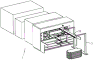
As shown in fig. 1 and 2, the automatic paper board nail sticking and packaging assembly line comprises an integrated machine body 1, wherein the integrated machine body 1 comprises a workbench 2 which is positioned at a feeding end and used for placing a paper board stack, a rack 3 is arranged on one side of the workbench 2, and a cross beam 31 is fixedly arranged on the rack 3 along a feeding direction.
As shown in fig. 2 and 3, a sliding seat 4 is slidably disposed on the cross beam 31, a dovetail groove 311 is disposed on a side wall of the cross beam 31 along a length direction thereof, a dovetail block (not shown) slidably connected with the dovetail groove 311 is fixedly disposed on the sliding seat 4, and the dovetail groove 311 is adapted to the dovetail block. The cross beam 31 is provided with a driving mechanism 5 for driving the sliding seat 4 to move along the cross beam 31, the driving mechanism 5 comprises a screw rod 51 and a second motor 52, the screw rod 51 is rotatably arranged on the cross beam 31 and is in threaded connection with the sliding seat 4, the second motor 52 is fixedly arranged on the cross beam 31, and an output shaft of the second motor 52 is coaxially and fixedly connected with the screw rod 51.
As shown in fig. 2 and 3, a mounting seat 41 is movably disposed below the sliding seat 4, a lifting mechanism for driving the mounting seat 41 to lift is disposed on the mounting seat 41, a guide through hole 43 is disposed on the sliding seat 4 along a vertical direction, the lifting mechanism includes a third pneumatic cylinder 42 fixedly disposed on the sliding seat 4, and a piston rod of the third pneumatic cylinder 42 passes through the guide through hole 43 and is fixedly connected to the mounting seat 41.
As shown in fig. 3 and 4, a mounting frame 8 is arranged below the mounting base 41, and a rotating mechanism 7 for driving the mounting frame 8 to rotate on a horizontal plane is arranged on the mounting base 41; slewing mechanism 7 includes worm wheel 71, worm 72, pivot 73 and three 74 of motor, and the vertical rotation of pivot 73 sets up on mount pad 41, pivot 73 and mounting bracket 8 fixed connection, and worm wheel 71 is coaxial fixed to be set up on pivot 73, and three 74 of motor are fixed to be set up on mount pad 41, and the coaxial fixed setting of worm 72 is on the output shaft of three 74 of motor, and worm 72 and worm wheel 71 mesh, the fixed spacing platform 731 that is provided with on the pivot 73, spacing platform 731 and the roof butt of mount pad 41.
When the mounting rack works, the third motor 74 is started, the third motor 74 drives the worm 72 to rotate, the worm 72 drives the worm wheel 71 to rotate, and the worm wheel 71 drives the rotating shaft 73 to rotate, so that the mounting rack 8 is driven to rotate; the worm wheel 71 is engaged with the worm 72 to prevent the mounting rack 8 from rotating automatically, and the limiting table 731 is disposed to prevent the rotating shaft 73 from moving downward under the action of gravity.
As shown in fig. 3, a support rod 81 for supporting the cardboard stack is arranged on the mounting rack 8 in a sliding manner along the horizontal direction, a mounting beam 84 is horizontally and fixedly arranged at the bottom of the mounting rack 8, two support rods 81 are arranged in parallel, the support rod 81 is arranged in the mounting beam 84 in a sliding manner, two support rods 81 are fixedly connected with a connecting plate 812, the upper surface of the support rod 81 is a plane, a guide inclined plane 811 is arranged at one end of the support rod 81 far away from the connecting plate 812, and the guide inclined plane 811 is arranged by inclining downwards the upper surface of the support rod 81 so as to be smoothly inserted into the cardboard stack. The mounting frame 8 is provided with a driving source 82 for driving the support rod 81 to slide, the driving source 82 is a second pneumatic cylinder fixedly arranged on the mounting beam 84, and a piston rod of the second pneumatic cylinder is fixedly connected with the connecting plate 812.
As shown in fig. 3, the mounting frame 8 is provided with a vertical rod 83, a push plate 831 perpendicular to the vertical rod 83 is fixedly arranged at the bottom end of the vertical rod 83, the thickness of the push plate 831 is 1-1.5cm, a driving member for driving the vertical rod 83 to approach or leave the cardboard pile is arranged on the mounting frame 8, a sleeve 833 is slidably sleeved on the vertical rod 83, the driving member is a first pneumatic cylinder 832 hinged to the mounting frame 8, and a piston rod of the first pneumatic cylinder 832 is hinged to the sleeve 833.
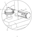
As shown in fig. 3, a lifting component for driving the upright rod 83 to ascend is arranged on the mounting frame 8, the lifting component includes a first motor 91, a pull rope 92 and a reel 93, the first motor 91 is fixedly arranged on the mounting frame 8, the reel 93 is coaxially and fixedly arranged on an output shaft of the first motor 91, the pull rope 92 is wound on the reel 93, one end of the pull rope 92 is fixedly connected with the reel 93, and the other end of the pull rope 92 is fixedly connected with the upright rod 83.
Before the supporting rod 81 lifts up the paper boards of the paper board stack, a first air cylinder 832 is started, the first air cylinder 832 drives a sleeve 833 to move, the sleeve 833 drives the vertical rod 83 to move towards the paper board stack, so that a push plate 831 on the vertical rod 83 pushes a small amount of paper boards to move a small distance in a direction away from the push plate 831, a first motor 91 is started, the first motor 91 drives a reel 93 to rotate and drives a pull rope 92 to move upwards, the pull rope 92 drives the vertical rod 83 and the push plate 831 to move upwards, and the push plate 831 drives the paper boards above the push plate 831 to lift upwards; so that a certain gap is left between the paper board on the push plate 831 and the paper board under the push plate 831, so that the support rod 81 can be inserted conveniently, and the operation is convenient. Similarly, when the cardboard is fed, after the supporting rod 81 and the cardboard pile are placed on the workbench 2, the cardboard pile is lifted up by a small distance by the pushing plate 831, so that the supporting rod 81 can be conveniently and smoothly drawn out.
As shown in fig. 2, two fixing plates 21 are vertically and fixedly disposed on the worktable 2, a pressing plate 22 is slidably disposed on the two fixing plates 21 perpendicular to the fixing plates 21, a pressing cylinder 211 for driving the pressing plate 22 to press the paper board is fixedly disposed on a side wall of the fixing plate 21 far away from the other fixing plate 21, and a piston rod of the pressing cylinder 211 penetrates through the fixing plate 21 and is fixedly connected with the pressing plate 22. The fixed plate 21 is slidably provided with a guide rod 212 in a penetrating manner, the guide rod 212 is perpendicular to the fixed plate 21, the guide rod 212 is fixedly connected with the pressing plate 22, the top wall of the pressing plate 22 is fixedly provided with a guide plate 221, the guide plate 221 is inclined towards the center of the two pressing plates 22, and the distance between the two guide plates 221 far away from one end of the pressing plate 22 is larger.
After the paperboard stack is placed on the workbench 2, the abutting cylinder 211 is started, and the abutting cylinder 211 drives the two abutting plates 22 to continuously abut against the two sides of the paperboard so as to enable the paperboard stack to be beaten up; the guide plate 221 is provided to facilitate smooth placement of the stack of sheets on the table 2 from above the holding-down plate 22.
The specific working process is as follows: in the actual production process, the corrugated boards need to be conveyed to the workbench 2 through the conveyor, and the corrugated boards are stacked into a higher paperboard stack, and after the number of the corrugated boards on the workbench 2 is reduced to a certain degree, the corrugated boards of the paperboard stack need to be added to the workbench 2 in time.
When the device works, the mounting frame 8 is opposite to a paperboard stack, the first pneumatic cylinder 832 is started firstly, the first pneumatic cylinder 832 drives the sleeve 833 to move, and the sleeve 833 drives the vertical rod 83 to move towards the paperboard stack, so that the push plate 831 on the vertical rod 83 pushes a small amount of paperboards to move a small distance towards the direction far away from the push plate 831; at this time, the first motor 91 is started, the first motor 91 drives the reel 93 to rotate, the pull rope 92 is driven to move upwards, the pull rope 92 drives the vertical rod 83 and the push plate 831 to move upwards, the push plate 831 drives the paper boards above the push plate 831 to lift upwards, and a certain gap is reserved between the paper boards on the push plate 831 and the paper boards below the push plate 831.
Then, the driving source 82 drives the supporting rod 81 to move, so that the supporting rod 81 is smoothly inserted into the cardboard stack, then the third pneumatic cylinder 42 is started to drive the mounting seat 41 to ascend, the mounting seat 41 drives the mounting frame 8 and the cardboard stack on the supporting rod 81 to be lifted, the second motor 52 is started, the second motor 52 drives the screw rod 51 to rotate, and the screw rod 51 drives the sliding seat 4 to move towards the direction close to the workbench 2 along the cross beam 31.
Simultaneously with the movement of the sliding seat 4, the third motor 74 is started, the third motor 74 drives the worm 72 to rotate, the worm 72 drives the worm wheel 71 to rotate, the worm wheel 71 drives the rotating shaft 73 to rotate, and therefore the mounting rack 8 is driven to rotate, and the rotation is usually 180 DEG0So that the mounting rack 8 drives the paperboard pile on the supporting rod 81 to rotate to the position opposite to the workbench 2. When the driving mechanism 5 drives the cardboard pile on the supporting rod 81 to move right above the worktable 2, the third pneumatic cylinder 42 drives the cardboard pile to be installedThe seat 41 is lowered until the stack of boards is successfully placed on the table 2.
The pulling rod and the pushing plate 831 are driven by the lifting assembly to lift the paperboard stack upwards for a short distance, and finally the driving source 82 drives the supporting rod 81 to slide in the direction far away from the workbench 2 so as to pull the supporting rod 81 out of the paperboard stack, so that automatic feeding is completed, and the labor intensity of workers is reduced.
The embodiments of the present invention are preferred embodiments of the present invention, and the scope of the present invention is not limited by these embodiments, so: all equivalent changes made according to the structure, shape and principle of the invention are covered by the protection scope of the invention.
Claims (9)
1. The utility model provides an automatic nail packing assembly line that glues of cardboard, includes all-in-one body (1), all-in-one body (1) is used for placing workstation (2) that the cardboard was piled including being located the feed end, its characterized in that: a rack (3) is arranged on one side of the workbench (2), a cross beam (31) is fixedly arranged on the rack (3) along the feeding direction, a sliding seat (4) is arranged on the cross beam (31) in a sliding manner, and a driving mechanism (5) for driving the sliding seat (4) to move along the cross beam (31) is arranged on the cross beam (31);
an installation seat (41) is movably arranged below the sliding seat (4), and a lifting mechanism for driving the installation seat (41) to lift is arranged on the installation seat (41);
an installation frame (8) is arranged below the installation base (41), and a rotating mechanism (7) for driving the installation frame (8) to rotate on the horizontal plane is arranged on the installation base (41);
a supporting rod (81) for bearing the paperboard stack is arranged on the mounting rack (8) in a sliding mode along the horizontal direction, and a driving source (82) for driving the supporting rod (81) to slide is arranged on the mounting rack (8); be provided with pole setting (83) on mounting bracket (8), the bottom mounting of pole setting (83) is provided with push pedal (831) of perpendicular pole setting (83), and the thickness of push pedal (831) is 1-1.5cm, be provided with on mounting bracket (8) and be used for driving pole setting (83) to being close to or keeping away from the driving piece of cardboard buttress, be provided with on mounting bracket (8) and be used for driving pole setting (83) lift-draw subassembly that rises.
2. The automatic paperboard staple-sticking and packaging line of claim 1, wherein: the lifting assembly comprises a first motor (91), a pull rope (92) and a reel (93), wherein the first motor (91) is fixedly arranged on the mounting frame (8), the reel (93) is coaxially and fixedly arranged on an output shaft of the first motor (91), the pull rope (92) is wound on the reel (93), and one end of the pull rope (92) is fixedly connected with the reel (93), and the other end of the pull rope is fixedly connected with the vertical rod (83).
3. The automatic paperboard staple-sticking and packaging line of claim 2, wherein: the sliding sleeve is equipped with sleeve pipe (833) on pole setting (83), the driving piece is for articulating first pneumatic cylinder (832) on mounting bracket (8), the piston rod of first pneumatic cylinder (832) is articulated with sleeve pipe (833).
4. A cardboard automatic staple line according to claim 1 or 3, characterized in that: the vertical fixed two fixed plates (21) that are provided with on workstation (2), two perpendicular to fixed plate (21) slides on fixed plate (21) and is provided with and supports clamp plate (22), the lateral wall of keeping away from another fixed plate (21) on fixed plate (21) is fixed to be provided with and is used for driving to support clamp plate (22) and support butt cylinder (211) of pressing the cardboard, the piston rod of butt cylinder (211) passes fixed plate (21) and supports clamp plate (22) fixed connection.
5. The automatic paperboard staple-sticking and packaging line of claim 4, wherein: guide bar (212) are worn to be equipped with in the slip on fixed plate (21), guide bar (212) with to clamp plate (22) fixed connection, the roof that supports clamp plate (22) is fixed and is provided with deflector (221), deflector (221) set up towards the center slope that two support clamp plate (22), and keep away from the distance between two deflector (221) that support clamp plate (22) one end great.
6. The automatic paperboard staple-sticking and packaging line of claim 1, wherein: slewing mechanism (7) include worm wheel (71), worm (72), pivot (73) and three (74) of motor, pivot (73) vertical rotation sets up on mount pad (41), pivot (73) and mounting bracket (8) fixed connection, the coaxial fixed of worm wheel (71) sets up on pivot (73), three (74) of motor are fixed to be set up on mount pad (41), the coaxial fixed setting of worm (72) is on the output shaft of three (74) of motor, and worm (72) and worm wheel (71) mesh, the fixed spacing platform (731) that is provided with on pivot (73), the roof butt of spacing platform (731) and mount pad (41).
7. The automatic paperboard staple-sticking and packaging line of claim 1, wherein: the dovetail groove (311) has been seted up along self length direction to the lateral wall of crossbeam (31), fixed being provided with on sliding seat (4) with dovetail (311) sliding connection's dovetail piece, dovetail (311) and dovetail piece looks adaptation.
8. The automatic paperboard staple-binding baling line of claim 7, wherein: the driving mechanism (5) comprises a screw rod (51) and a second motor (52), the screw rod (51) is rotatably arranged on the cross beam (31) and is in threaded connection with the sliding seat (4), the second motor (52) is fixedly arranged on the cross beam (31), and an output shaft of the second motor (52) is coaxially and fixedly connected with the screw rod (51).
9. The automatic paperboard staple-sticking and packaging line of claim 1, wherein: guide through hole (43) have been seted up along vertical direction on sliding seat (4), elevating system is including setting firmly third pneumatic cylinder (42) on sliding seat (4), the piston rod of third pneumatic cylinder (42) passes guide through hole (43) and mount pad (41) fixed connection.
Priority Applications (1)
| Application Number | Priority Date | Filing Date | Title |
|---|---|---|---|
| CN201910377667.6A CN110053835B (en) | 2019-05-08 | 2019-05-08 | Automatic paper board nail sticking and packaging assembly line |
Applications Claiming Priority (1)
| Application Number | Priority Date | Filing Date | Title |
|---|---|---|---|
| CN201910377667.6A CN110053835B (en) | 2019-05-08 | 2019-05-08 | Automatic paper board nail sticking and packaging assembly line |
Publications (2)
| Publication Number | Publication Date |
|---|---|
| CN110053835A CN110053835A (en) | 2019-07-26 |
| CN110053835B true CN110053835B (en) | 2021-03-19 |
Family
ID=67322386
Family Applications (1)
| Application Number | Title | Priority Date | Filing Date |
|---|---|---|---|
| CN201910377667.6A Active CN110053835B (en) | 2019-05-08 | 2019-05-08 | Automatic paper board nail sticking and packaging assembly line |
Country Status (1)
| Country | Link |
|---|---|
| CN (1) | CN110053835B (en) |
Families Citing this family (1)
| Publication number | Priority date | Publication date | Assignee | Title |
|---|---|---|---|---|
| CN114906379A (en) * | 2022-06-06 | 2022-08-16 | 固丽纸业(上海)有限公司 | Corrugated box production is with binding device of corrugated container board of being convenient for |
Family Cites Families (6)
| Publication number | Priority date | Publication date | Assignee | Title |
|---|---|---|---|---|
| US4778323A (en) * | 1985-09-13 | 1988-10-18 | Besser Company | Bag palletizing system and method |
| DE4038133A1 (en) * | 1990-11-30 | 1992-06-04 | Bahmueller Masch W | PALLETIZING MACHINE |
| ITBO20030490A1 (en) * | 2003-08-08 | 2005-02-09 | Kpl Packaging Spa | METHOD AND DEVICE FOR THE FORMATION AND LEVY OF SHEETS |
| ITBO20080232A1 (en) * | 2008-04-16 | 2009-10-17 | Giben Int Spa | APPARATUS FOR FORMING PANELS PACKAGES. |
| CN106044194B (en) * | 2016-07-13 | 2018-03-06 | 温州市巨能机械有限公司 | A kind of scraps of paper conveying device of paper cup making machine |
| CN109607172A (en) * | 2018-12-17 | 2019-04-12 | 成都保得物流有限公司 | A kind of assembly line automatic dischargingapparatus |
-
2019
- 2019-05-08 CN CN201910377667.6A patent/CN110053835B/en active Active
Also Published As
| Publication number | Publication date |
|---|---|
| CN110053835A (en) | 2019-07-26 |
Similar Documents
| Publication | Publication Date | Title |
|---|---|---|
| CN213356014U (en) | Deviation rectifying and aligning equipment for corrugated case | |
| CN105775722A (en) | Storage and distribution device for pallets | |
| CN212687118U (en) | Finished product automatic collecting device of full-automatic die cutting machine | |
| CN211733113U (en) | Wood board feeding device for floor gluing line | |
| CN209257541U (en) | A kind of Full-automatic cutting trigger | |
| CN110053835B (en) | Automatic paper board nail sticking and packaging assembly line | |
| CN210558412U (en) | Automatic lifting type paper stack stacking and patting device | |
| CN213593765U (en) | Automatic folding forming equipment of double-end carton | |
| CN213504875U (en) | Novel sheet material is automatic to be piled up device | |
| CN115366206B (en) | Bamboo carriage bottom plate processing is with bamboo chip splicing apparatus | |
| CN110001128A (en) | A kind of two-piece carton nailing | |
| CN112441463A (en) | Automatic over-and-under type paper buttress pile up neatly and clap neat device | |
| CN110614572A (en) | Automatic pipe cutting system | |
| CN213593764U (en) | A folding forming mechanism for carton | |
| CN213833918U (en) | Material collecting device for label cutting machine | |
| CN212919673U (en) | Automatic material receiving platform of paper cutting machine | |
| CN211619185U (en) | Feeding device for paperboard blank | |
| CN213564619U (en) | Conveying device of full-automatic box pasting machine | |
| CN209776860U (en) | A carton top cap turns over a transfer chain for floor packing | |
| CN214137555U (en) | Discharge device of carton binding machine | |
| CN210911586U (en) | Board pasting machine | |
| CN110815931B (en) | Single-page carton stapler | |
| CN207792073U (en) | A kind of paper for daily use packing case delivery apparatus | |
| CN217228013U (en) | Feeding mechanism for paperboard binding machine | |
| CN217322712U (en) | Automatic high-efficient paper collecting device |
Legal Events
| Date | Code | Title | Description |
|---|---|---|---|
| PB01 | Publication | ||
| PB01 | Publication | ||
| SE01 | Entry into force of request for substantive examination | ||
| SE01 | Entry into force of request for substantive examination | ||
| GR01 | Patent grant | ||
| GR01 | Patent grant |