CN110035196B - Image forming apparatus and control method of image forming apparatus - Google Patents
Image forming apparatus and control method of image forming apparatus Download PDFInfo
- Publication number
- CN110035196B CN110035196B CN201910216380.5A CN201910216380A CN110035196B CN 110035196 B CN110035196 B CN 110035196B CN 201910216380 A CN201910216380 A CN 201910216380A CN 110035196 B CN110035196 B CN 110035196B
- Authority
- CN
- China
- Prior art keywords
- image forming
- forming apparatus
- unit
- screen
- motor
- Prior art date
- Legal status (The legal status is an assumption and is not a legal conclusion. Google has not performed a legal analysis and makes no representation as to the accuracy of the status listed.)
- Active
Links
Images


Classifications
-
- H—ELECTRICITY
- H04—ELECTRIC COMMUNICATION TECHNIQUE
- H04N—PICTORIAL COMMUNICATION, e.g. TELEVISION
- H04N1/00—Scanning, transmission or reproduction of documents or the like, e.g. facsimile transmission; Details thereof
- H04N1/00885—Power supply means, e.g. arrangements for the control of power supply to the apparatus or components thereof
- H04N1/00888—Control thereof
- H04N1/00896—Control thereof using a low-power mode, e.g. standby
-
- B—PERFORMING OPERATIONS; TRANSPORTING
- B41—PRINTING; LINING MACHINES; TYPEWRITERS; STAMPS
- B41J—TYPEWRITERS; SELECTIVE PRINTING MECHANISMS, i.e. MECHANISMS PRINTING OTHERWISE THAN FROM A FORME; CORRECTION OF TYPOGRAPHICAL ERRORS
- B41J29/00—Details of, or accessories for, typewriters or selective printing mechanisms not otherwise provided for
- B41J29/38—Drives, motors, controls or automatic cut-off devices for the entire printing mechanism
-
- G—PHYSICS
- G03—PHOTOGRAPHY; CINEMATOGRAPHY; ANALOGOUS TECHNIQUES USING WAVES OTHER THAN OPTICAL WAVES; ELECTROGRAPHY; HOLOGRAPHY
- G03G—ELECTROGRAPHY; ELECTROPHOTOGRAPHY; MAGNETOGRAPHY
- G03G15/00—Apparatus for electrographic processes using a charge pattern
- G03G15/50—Machine control of apparatus for electrographic processes using a charge pattern, e.g. regulating differents parts of the machine, multimode copiers, microprocessor control
- G03G15/5004—Power supply control, e.g. power-saving mode, automatic power turn-off
-
- G—PHYSICS
- G06—COMPUTING; CALCULATING OR COUNTING
- G06F—ELECTRIC DIGITAL DATA PROCESSING
- G06F1/00—Details not covered by groups G06F3/00 - G06F13/00 and G06F21/00
- G06F1/26—Power supply means, e.g. regulation thereof
- G06F1/32—Means for saving power
- G06F1/3203—Power management, i.e. event-based initiation of a power-saving mode
- G06F1/3234—Power saving characterised by the action undertaken
- G06F1/325—Power saving in peripheral device
- G06F1/3284—Power saving in printer
-
- H—ELECTRICITY
- H04—ELECTRIC COMMUNICATION TECHNIQUE
- H04N—PICTORIAL COMMUNICATION, e.g. TELEVISION
- H04N1/00—Scanning, transmission or reproduction of documents or the like, e.g. facsimile transmission; Details thereof
- H04N1/0035—User-machine interface; Control console
- H04N1/00405—Output means
- H04N1/00474—Output means outputting a plurality of functional options, e.g. scan, copy or print
-
- H—ELECTRICITY
- H04—ELECTRIC COMMUNICATION TECHNIQUE
- H04N—PICTORIAL COMMUNICATION, e.g. TELEVISION
- H04N1/00—Scanning, transmission or reproduction of documents or the like, e.g. facsimile transmission; Details thereof
- H04N1/0035—User-machine interface; Control console
- H04N1/00405—Output means
- H04N1/00408—Display of information to the user, e.g. menus
- H04N1/00411—Display of information to the user, e.g. menus the display also being used for user input, e.g. touch screen
-
- H—ELECTRICITY
- H04—ELECTRIC COMMUNICATION TECHNIQUE
- H04N—PICTORIAL COMMUNICATION, e.g. TELEVISION
- H04N1/00—Scanning, transmission or reproduction of documents or the like, e.g. facsimile transmission; Details thereof
- H04N1/00912—Arrangements for controlling a still picture apparatus or components thereof not otherwise provided for
- H04N1/00928—Initialisation or control of normal start-up or shut-down, i.e. non failure or error related
-
- H—ELECTRICITY
- H04—ELECTRIC COMMUNICATION TECHNIQUE
- H04N—PICTORIAL COMMUNICATION, e.g. TELEVISION
- H04N2201/00—Indexing scheme relating to scanning, transmission or reproduction of documents or the like, and to details thereof
- H04N2201/0077—Types of the still picture apparatus
- H04N2201/0094—Multifunctional device, i.e. a device capable of all of reading, reproducing, copying, facsimile transception, file transception
-
- Y—GENERAL TAGGING OF NEW TECHNOLOGICAL DEVELOPMENTS; GENERAL TAGGING OF CROSS-SECTIONAL TECHNOLOGIES SPANNING OVER SEVERAL SECTIONS OF THE IPC; TECHNICAL SUBJECTS COVERED BY FORMER USPC CROSS-REFERENCE ART COLLECTIONS [XRACs] AND DIGESTS
- Y02—TECHNOLOGIES OR APPLICATIONS FOR MITIGATION OR ADAPTATION AGAINST CLIMATE CHANGE
- Y02D—CLIMATE CHANGE MITIGATION TECHNOLOGIES IN INFORMATION AND COMMUNICATION TECHNOLOGIES [ICT], I.E. INFORMATION AND COMMUNICATION TECHNOLOGIES AIMING AT THE REDUCTION OF THEIR OWN ENERGY USE
- Y02D10/00—Energy efficient computing, e.g. low power processors, power management or thermal management
-
- Y—GENERAL TAGGING OF NEW TECHNOLOGICAL DEVELOPMENTS; GENERAL TAGGING OF CROSS-SECTIONAL TECHNOLOGIES SPANNING OVER SEVERAL SECTIONS OF THE IPC; TECHNICAL SUBJECTS COVERED BY FORMER USPC CROSS-REFERENCE ART COLLECTIONS [XRACs] AND DIGESTS
- Y02—TECHNOLOGIES OR APPLICATIONS FOR MITIGATION OR ADAPTATION AGAINST CLIMATE CHANGE
- Y02D—CLIMATE CHANGE MITIGATION TECHNOLOGIES IN INFORMATION AND COMMUNICATION TECHNOLOGIES [ICT], I.E. INFORMATION AND COMMUNICATION TECHNOLOGIES AIMING AT THE REDUCTION OF THEIR OWN ENERGY USE
- Y02D30/00—Reducing energy consumption in communication networks
- Y02D30/50—Reducing energy consumption in communication networks in wire-line communication networks, e.g. low power modes or reduced link rate
Landscapes
- Engineering & Computer Science (AREA)
- Multimedia (AREA)
- Signal Processing (AREA)
- Physics & Mathematics (AREA)
- General Physics & Mathematics (AREA)
- Theoretical Computer Science (AREA)
- Microelectronics & Electronic Packaging (AREA)
- General Engineering & Computer Science (AREA)
- Facsimiles In General (AREA)
- Accessory Devices And Overall Control Thereof (AREA)
- Control Or Security For Electrophotography (AREA)
Abstract
The invention discloses an image forming apparatus and a control method of the image forming apparatus. An image forming apparatus capable of shifting to a power saving state includes: a printing unit configured to control a printing control unit of the printing unit, and a power supply unit configured to supply power to the printing control unit when the image forming apparatus returns from a power saving state, wherein the printing control unit supplied with power by the power supply unit performs initialization on the printing unit in a case where a printing screen for executing a printing function is set as an initial screen to be displayed when the image forming apparatus returns from the power saving state, and wherein the printing control unit does not perform initialization on the printing unit in a case where a selection screen for selecting the printing function is set as an initial screen to be displayed when the image forming apparatus returns from the power saving state.
Description
The present application is a divisional application of an invention patent application entitled "image forming apparatus and method for controlling image forming apparatus" filed on 19/05/2015 with application number 201510257111.5.
Technical Field
The present invention relates to an image forming apparatus and a method of controlling the image forming apparatus.
Background
There is proposed a method of powering on a printer device, a scanner device, and a Facsimile (FAX) device in an image forming apparatus when a user is found to use the printer device, the scanner device, and the FAX device due to an improvement in a power saving function.
For example, the scanner device is powered on only when the scan function is used, the printer device is powered on only when the print function is used, and the FAX device is powered on only when the FAX function is used. Meanwhile, the substrate and the chip respectively associated with the printer device, the scanner device, and the FAX device are powered on only when they are used.
In a method of powering on a printer device, a scanner device, and a FAX device when a user uses these devices, the image forming apparatus can satisfy power saving requirements.
However, after determining that the image forming apparatus executes the processing, the printer device, the scanner device, and the FAX device are powered on and initialized. Therefore, it takes time to perform initialization such as power-on, software initialization, or hardware preprocessing. Therefore, it takes time to start the printer device, the scanner device, and the FAX device, and this time delays the execution of the process, thereby reducing the convenience of the user.
With the improvement of the mute performance, a method of initializing a printer device and a scanner device when a user is found to be using the printer device and the scanner device in an image forming apparatus is proposed. More specifically, the image forming apparatus powers on the printer device and the scanner device at startup and return from sleep. However, the image forming apparatus returns in an operation waiting state, which is a state in which an operation is performed when the use of the printer device and the scanner device is found.
The operation waiting state is a state in which the printer device and the scanner device are powered on without moving the movable unit. For example, each motor or polygon mirror in the sheet feeding unit, the sheet discharging unit, and the marking unit is not operated, and the temperature adjustment of the marking unit is not performed. The motor in the original feeding unit is not operated, and the home position of the scanner unit is not adjusted.
On the other hand, the operation wait cancellation state is a state in which the printer apparatus and the scanner apparatus are powered on while the above-described processing is executed. By controlling the movable unit not to move, power is saved in the operation waiting state more than in the operation waiting cancellation state. In a method of initializing a printer device and a scanner device when a user uses these devices, the image forming apparatus can satisfy a mute performance.
However, the printer device and the scanner device are initialized after determining that the image forming apparatus executes the processing. Therefore, although power-on and software initialization have ended, it takes time to perform initialization such as hardware preprocessing. Therefore, it takes time to start the printer device and the scanner device, which delays the execution of the process, thereby reducing the convenience of the user.
Further, there is proposed a method of returning the image forming apparatus from sleep in a state where the printer device and the scanner device are powered on in the image forming apparatus when the copy screen is set to default, although the image forming apparatus normally returns from sleep in a state where the printer device and the scanner device are powered off. In this method, power saving and mute performance can be satisfied. However, when the copy screen is not set as a default, the printer apparatus and the scanner apparatus are powered on. Therefore, the user is not allowed to immediately use the image forming apparatus, thereby reducing the convenience of the user.
In japanese patent laid-open No. 2012-191369, in the case where the copy screen is set as the initial screen at the time of returning from sleep, the image forming apparatus returns from sleep in a state where the scanner device and the printer device are powered on. However, when the copy screen is not set as the initial screen, the scanner apparatus and the printer apparatus remain unpowered.
Therefore, when the copy screen is not set as the initial screen, the user cannot immediately use the image forming apparatus, thereby reducing the convenience of the user.
Disclosure of Invention
The present invention is directed to providing a technique that enables the initialization processing of each device in an image forming apparatus to be switched according to the function of a displayed setting screen when the image forming apparatus returns from a sleep mode.
According to an aspect of the present invention, there is provided an image forming apparatus capable of shifting to a power saving state, the image forming apparatus comprising: a printing unit configured to execute a printing process; a printing control unit configured to output a driving signal to at least one motor configured in the printing unit; a power supply unit configured to supply power to the at least one motor, a switch disposed between the at least one motor and the power supply unit; a control unit configured to open and close the switch, and output a predetermined signal to the print control unit, wherein the print control unit is capable of outputting the driving signal when the predetermined signal is not input, and not outputting the driving signal when the predetermined signal is input; a display; and a storage unit that stores information representing an initial screen preset by a user to be displayed when the image forming apparatus returns from the power saving state, wherein, in accordance with a return instruction to return the image forming apparatus from the power saving state, the control unit: (i) open the switch, and (ii) output the predetermined signal to the print control unit or not output the predetermined signal to the print control unit based on the information stored in the storage unit.
Other features of the present invention will become apparent from the following detailed description of exemplary embodiments with reference to the attached drawings.
Drawings
Fig. 1 is a block diagram illustrating a configuration of an image forming system.
Fig. 2 is a plan view illustrating the configuration of the operation unit.
Fig. 3 illustrates a User Interface (UI) screen displayed on a Liquid Crystal Display (LCD) touch panel.
Fig. 4A-a and 4A-B illustrate UI screens displayed on an LCD touch panel.
Fig. 4B-a and 4B-B illustrate UI screens displayed on the LCD touch panel.
Fig. 5 is a block diagram illustrating a configuration of the controller.
Fig. 6 is a block diagram illustrating a configuration of the controller.
Fig. 7 is a block diagram illustrating a power supply configuration of the image forming apparatus.
Fig. 8 is a block diagram illustrating a hardware configuration for monitoring a power supply.
Fig. 9 is a timing chart illustrating a power supply state of the image forming apparatus.
Fig. 10 is a flowchart illustrating a control method of the image forming apparatus.
Fig. 11 is a flowchart illustrating a control method of the image forming apparatus.
Fig. 12 is a timing chart illustrating a power supply state of the image forming apparatus.
Fig. 13 is a flowchart illustrating a control method of the image forming apparatus.
Fig. 14 is a timing chart illustrating a power supply state of the image forming apparatus.
Fig. 15 is a flowchart illustrating a control method of the image forming apparatus.
Detailed Description
Exemplary embodiments of the present invention will be described below with reference to the accompanying drawings.
< description of System configuration >
Fig. 1 is a block diagram illustrating a configuration of an image forming system according to a first exemplary embodiment of the present invention. In fig. 1, a multi-function external device including devices that respectively perform a printing function, a scanner function, and a data communication function is taken as an example.
In fig. 1, the image forming apparatus 1 can receive a job from a computer 9 via a Local Area Network (LAN) 8. The number of computers to be connected to the image forming apparatus 1 may be one or more.
The scanner device 2 serves as a device that optically reads an image from an original and converts the read image into a digital image. The printer apparatus 4 serves as an apparatus that outputs a digital image from the scanner apparatus 2 to a sheet. The operation unit 5 includes a touch panel and a hardware key for receiving a setting of the image forming apparatus 1 by a user and displaying a processing state. The hard disk 6 stores digital images and control programs. The FAX device 7 transmits/receives digital images to/from a telephone line. The controller 3 is connected with the scanner device 2, the printer device 4, the operation unit 5, the hard disk 6, and the FAX device 7, and sends instructions to the respective modules to execute jobs on the image forming apparatus 1.
The image forming apparatus 1 can also input/output digital images to/from the computer 9 via the LAN 8, and transmit jobs and designated devices. The scanner device 2 includes an original feeding unit 21 capable of automatically sequentially setting a bundle of originals, and a scanner unit 22 capable of optically scanning originals and converting the originals into digital images. The image data acquired by the conversion is sent to the controller 3.
The printer apparatus 4 includes a sheet feeding unit 42 capable of sequentially feeding sheets one by one from a sheet bundle, a marking unit 41 for printing image data on the fed sheet, and a sheet discharging unit 43 for discharging the sheet on which the image data has been printed.
The finisher apparatus 700 performs processes such as discharging, finishing, stapling, punching, and cutting on sheets output from the sheet discharge unit 43 of the printer device 4 in the image forming apparatus 1.
Examples of various jobs that can be executed by the image forming apparatus 1 will be described below.
[ copy function ]
The image forming apparatus 1 has a copy function of: the image read from the scanner device 2 is stored on the hard disk 6 and the recorded image is printed using the printer device 4 at the same time.
[ image Transmission function ]
The image forming apparatus 1 has the following image transmission function: the image read from the scanner device 2 is transmitted to the computer 9 via the LAN 8.
[ image storage function ]
The image forming apparatus 1 has the following image storage function: the image read from the scanner device 2 is stored on the hard disk 6 and the recorded image is transmitted and printed as necessary.
[ image printing function ]
The image forming apparatus 1 has the following image printing functions: analyzes, for example, a Page Description Language (PDL) transmitted from the computer 9, and prints the analyzed PDL using the printer device 4.
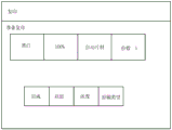
Fig. 2 is a plan view illustrating the configuration of the operation unit 5 shown in fig. 1. An operation unit 5(I/F) connected to the controller 3 and including a Liquid Crystal Display (LCD) touch panel 800 provides a user interface for operating the image input/output system.
In fig. 2, main mode setting and status display are performed using the LCD touch panel 800. The numeric keypad 801 is used to input numeric values 0 to 9. If the image forming apparatus 1 is managed by a department, an Identification (ID) key 802 is used when a department number and a password are input.
A reset key 803 is used to reset the setting mode, a guide key 804 is used to display a description screen for each mode, a user mode key 805 is used to enter a user mode screen, and an interrupt key 806 is used to execute interrupt copying.
A start key 807 is used to start a copy operation, and a stop key 808 is used to stop a copy job being executed. When the power saving key 809 is pressed, the backlight of the LCD touch panel 800 is turned off to cause the image forming apparatus 1 to enter a sleep mode (second power state).
When the counter ok key 810 is pressed, a count screen for displaying the total number of copies used so far is displayed on the LCD touch panel 800. The adjustment key 811 is used to adjust the contrast of the LCD touch panel 800.
A Light Emitting Diode (LED)812 indicates that an image is being stored in the image memory while a job is being executed, an error LED 813 indicates that the image forming apparatus 1 is in an error state such as a paper jam or a door open, and a power LED 814 indicates that a main switch of the image forming apparatus 1 is on.
A "copy" key 851 is a conversion key to the copy function screen.
The "scan and store" key 852 is a shift key to a function screen for storing an image that has been scanned by the scanner device 2 into the HDD 6. The "print stored original" key 853 is a shift key to a function for printing an image stored in the HDD 6 using the printer device 4.
The "scan and transmit" key 854 is a shift key to a function for transmitting an image that has been scanned by the scanner device 2 to the computer 9 via the LAN 8. The "FAX" key 855 is a conversion key to a function for printing data that has been received from a telephone line by the FAX device 7 using the printer device 4 via the controller 3. The "visible power" key 856 is a shift key to a function for confirming the power state of the image forming apparatus 1 using the LCD touch panel 800.
A screen displayed on LCD touch panel 800 by image forming apparatus 1 when copy key 851 is pressed will be described below with reference to fig. 3.
Fig. 3 illustrates an example of a User Interface (UI) screen displayed on the LCD touch panel 800 illustrated in fig. 2. This example is an example of a setting change screen. A screen displayed on the LCD touch panel 800 when starting up and returning from sleep is referred to as an initial screen.
In fig. 3, when a "copy" key 861 for changing the initial screen image to a copy screen image is pressed, the screen images illustrated in fig. 4A-a are displayed on the LCD touch panel 800. If a scan and store key 862 for changing the initial screen to a scan and store screen is pressed, the screens illustrated in fig. 4A-B are displayed on the LCD touch panel 800.
A "print stored document" key 863 for changing the initial screen image to a "print stored document" screen image is pressed, and the screen image illustrated in fig. 4B-a is displayed on the LCD touch panel 800. Pressing a scan and send key 864 for changing the initial screen to the scan and send screen displays the screens illustrated in fig. 4B-B on the LCD touch panel 800.
Although the selectable keys include a plurality of keys other than the above-described keys such as the function selection screen displayed on the LCD touch panel 800 illustrated in fig. 2, a description thereof is omitted because of departing from the subject matter.
A block diagram of the controller 3 will be described below with reference to fig. 5. The controller 3 used as a module for a specific application of the present invention will be described with reference to fig. 5.
Fig. 5 is a block diagram illustrating a configuration of the controller 3 illustrated in fig. 1. The power supply state in this example is a standby state, i.e., a state in which power is supplied to all devices.
In fig. 5, the controller 3 includes a main board 200 and a sub board 220. The main board 200 is a so-called general-purpose Central Processing Unit (CPU) system. The main board 200 includes a CPU201 that controls the entire substrate, a boot Read Only Memory (ROM)202 that stores a boot program, a memory 203 that is used as a work memory by the CPU201, a bus controller 204 that has a bridge function with an external bus, and a nonvolatile memory 205 that can hold stored data even if power is turned off thereto.
Further, the main board 200 includes a disk controller 206 that controls a storage device, a flash disk 207 such as a Solid State Disk (SSD) serving as a storage device including a semiconductor device and having a relatively small capacity, and a USB controller 208 that can control a Universal Serial Bus (USB).
The USB memory 209, the operation unit 5, and the hard disk 6 are connected to the external motherboard 200. The CPU201 is connected to an interrupt controller 210, and further connected to a network controller 211, a Real Time Clock (RTC)212, a FAX device 7, an operation unit 5 having a software switch, and a USB controller 208.
The sub-board 220 includes a relatively small general-purpose CPU system and image processing hardware. The sub board 220 includes a CPU 221 that controls the entire sub board 220, a memory 223 used as a work memory by the CPU 221, a bus controller 224 having a bridge function with an external bus, and a nonvolatile memory 225 that can hold stored data and the like even if power is off. Further, the sub board 220 includes an image processor 227 performing real-time digital image processing and a device controller 226.
The scanner device 2 and the printer device 4 outside the sub board 220 exchange digital image data therebetween via the device controller 226. The CPU 221 directly controls the FAX device 7. The finisher device 700 processes the sheet discharged from the printer apparatus 4.
Fig. 5 is a simplified block diagram. Although the CPU201 and the CPU 221 each include many pieces of hardware around the CPU such as a chipset, a bus bridge, a clock generator, and the like, since it is not necessary to describe them in a granular manner, the description of these pieces of hardware is simplified. Such a block configuration is not intended to limit the present invention.
The operation of the controller 3 will be described using image copying using a sheet as an example.
When the user issues an instruction to copy an image from the operation unit 5, the CPU201 transmits an image reading instruction to the scanner device 2 via the CPU 221. The scanner device 2 optically scans a sheet original, converts the scanned sheet original into digital image data, and inputs the digital image data to the image processor 227 via the device controller 226. The image processor 227 performs Direct Memory Access (DMA) transfer to the memory 223 via the CPU 221, and temporarily stores digital image data in the memory 223.
When it is confirmed that a predetermined number or all of the digital image data has entered the memory 223, the CPU201 sends an image output instruction to the printer device 4 via the CPU 221.
The position of the image data on the memory 223 of the CPU 221 is notified to the image processor 227. The image data on the memory 223 is sent to the printer device 4 via the image processor 227 and the device controller 226 in accordance with a synchronization signal from the printer device 4.
The printer device 4 prints the digital image data on a sheet device.
When printing a plurality of copies of sheets, the CPU201 can store the image data on the memory 223 in the hard disk 6, and can transmit the image data to the printer apparatus 4 without receiving the image data from the scanner apparatus 2 for the second and subsequent print copies.
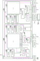
Fig. 6 is a block diagram illustrating the configuration of the controller 3 shown in fig. 1. The power state in this embodiment corresponds to a state in which the controller 3 is sleeping.
In the present exemplary embodiment, the sleep mode is a state in which the start time can be made earlier than the normal start time while suppressing the power consumption. When the user has not operated the image forming apparatus 1 for a predetermined period of time and when the user presses the software switch on the operation unit 5, the image forming apparatus 1 shifts to the sleep mode.
The controller 3 used as a module for a specific application of the present invention will be described with reference to fig. 6.
In the sleep mode, power is supplied from a power supply unit 301 described below to minimally necessary components such as the memory 203 on the controller 3 and the interrupt controller 210.
In the sleep mode, power is supplied to the network controller 211, the RTC 212, the USB controller 208, the software switch on the operation unit 5, various sensors, and a part of the FAX device 7, and the network controller 211, the RTC 212, and the USB controller 208 transmit an interrupt from sleep-back (return-from-sleep) to the interrupt controller 210.
More specifically, power is supplied from the power supply unit 301 to components other than the shaded portion in fig. 6 during the sleep mode. During the sleep mode, the interrupt controller 210 receives one or more interrupts such as a network incoming call, an RTC for detecting a timer and an alarm clock, a FAX for detecting an incoming call and an off-hook, a software switch, a sensor, and a USB for detecting an insertion/extraction and communication.
The interrupt controller 210 notifies the CPU201 of the received interrupt when the interrupt is received. The CPU201 executes processing for supplying power and returning the software state to the normal state after receiving the notification. However, the factor of return from sleep differs for each system. Therefore, the power supply in the sleep mode is not limited by this configuration.
Fig. 7 is a block diagram illustrating a power supply configuration of the image forming apparatus 1 shown in fig. 1. With respect to the configurations of the controller 3, the printer device 4, the interrupt controller 210, and the power supply unit 301 in the image forming apparatus 1, portions related to the present exemplary embodiment will be described below with reference to fig. 7.
In fig. 7, power is always supplied to the interrupt controller 210 via the path 302.
The interrupt controller 210 controls power supply of each unit in the image forming apparatus 1. More specifically, the interrupt controller 210 performs control (high level/low level) of an input/output (IO) signal V _ ON307 to switch ON/OFF (ON/OFF) of the relay switch 308. When the relay switch 308 is opened, power is supplied from the power supply unit 301 to the controller 3 via a path 309. Since the CPU201 sets a plurality of timer values in the interrupt controller 210 by communication, the interrupt controller 210 executes an operation set in advance when starting the timer.
The interrupt controller 210 performs control (high level/low level) of the IO signal P _ ON 310 to switch ON/off of the relay switch 311. When the relay switch 311 is turned on, power is supplied from the power supply unit 301 to the printer device 4 via a path 312. The interrupt controller 210 operates a predetermined IO signal in response to an instruction from the CPU 201. The IO signal 305 is a DCON _ levelwake signal connected to the CPU 320 in the printer device 4. When the printer device 4 is powered on while the DCON _ levelwake signal is enabled, the printer device 4 does not perform a specific operation for controlling the movable unit. Therefore, the movable unit does not emit driving noise.
The above-described specific operations include control of the rotating operation of the movable unit (e.g., the motor, the roller, the polygon mirror, the drums 321 to 324, and the FAN 325). When the scanner device 2 can be controlled by the interrupt controller 210 like the printer device 4, the contents of the scanner device 2 and the contents of the printer device 4 are repeated, and thus the description thereof is not repeated.
Fig. 8 is a block diagram illustrating a hardware configuration for monitoring the power supply of the controller 3 shown in fig. 1. The power supply control and reset circuit of the controller 3 will be described with emphasis.
In fig. 8, a reset circuit 601 is provided on the main board 200. A basic input/output system (BIOS)602 controls the basic portion of hardware (H/W) on the motherboard 200. The BIOS 602 is configured as dedicated H/W logic for monitoring power control of the present system through the interrupt controller 210. When an Application Specific Integrated Circuit (ASIC) is used, the dedicated H/W logic can be a small CPU system. A reset circuit 604 is provided on the sub board 220. An H/W group 605 is provided on each of the main board 200 and the sub board 220.
The internal state of the sync type H/W is reset by reset. Therefore, after the H/W circuits disposed in the respective synchronization H/W circuits are energized to supply power to the respective chips, the reset circuit needs to reset the respective synchronization H/W circuits.
A reset circuit is generally included in each substrate, and a reset operation is performed on the substrate.
In particular, the system for the main board 200 is a main substrate in the image forming apparatus 1, and includes the interrupt controller 210. The interrupt controller 210 performs control (high level/low level) of the IO signal V _ ON307 to open the relay switch 308, thereby controlling power supply in the main board 200 and the sub board 220.
When the CPU201 can normally operate, the system can be reset in response to an instruction from the CPU 201. When the interrupt controller 210 controls the IO signal V _ ON307 while power is not supplied to the CPU201, the relay switch 308 is opened and power is supplied to the controller 3.
In the image forming apparatus 1 having the above-described H/W configuration, for example, when the seesaw switch 313 is turned off, the CPU201 can receive the state of the seesaw switch 313 via the interrupt controller 210. More specifically, the CPU201 detects power-off to operate a shutdown sequence. When the CPU201 completes the shutdown processing, the interrupt controller 210 turns off the relay switch 308 and the relay switch 311. Thus, the system is completely shut down.
< Power supply processing in Start-Up >
The process for starting the image forming apparatus 1 will now be described. The operator turns on the interaction changeover switch 313 when using the image forming apparatus 1. Therefore, the interrupt controller 210 detects power-ON from the IO signal V _ ON 307. The relay switch 308 operates based ON the IO signal V _ ON307, thereby supplying power from the power supply unit 301 to the entire image forming apparatus 1.
The interrupt controller 210 supplies power to the entire system according to the time when the power is turned on, and in particular, energizes the controller 3, the printer apparatus 4, and the scanner apparatus 2 via the respective DC power supply paths. The CPU of each of the printer device 4 and the scanner device 2 starts an initialization operation by power-on. < Power supply State in sleep mode >
The sleep mode of the image forming apparatus 1 will now be described.
The sleep mode is a state in which the start time is made earlier than the normal start time while suppressing power consumption. When the user has not operated the image forming apparatus 1 for a predetermined period of time and when the user presses the power saving key 809 on the operation unit 5, the image forming apparatus 1 switches to the sleep mode.
The power supply condition of the hardware will now be described.
The power supplied from the power supply unit 301 is supplied to the controller 3 via a path 309. During the sleep mode, power is supplied to the following minimally necessary components such as the controller 3 and the operation unit 5. In the controller 3, the minimum necessary components include a memory 203, an interrupt controller 210, a network controller 211, an RTC 212, and a USB controller 208. In the operation unit 5, the minimum necessary components include a power saving key 809, a part FAX device 7, and various sensors. The return from sleep factor is different for each system. Thus, power supply during the sleep mode is not limited by this configuration.
The operation of the software will now be described.
During the sleep mode, the interrupt controller 210 receives one or more interrupts of a network, an RTC for detecting a timer and an alarm clock, a FAX for detecting incoming and off-hook, a power saving key 809, various sensors, and a USB for detecting plug/unplug and communication, etc. The interrupt controller 210 executes processing for notifying the CPU201 of the above-described return factor and returning to return the state of power supply and software to a normal state upon receiving the notification.
< Power supply State during deactivated State of Printer apparatus 4 and scanner apparatus 2 in Normal State >
Next, power supply of the image forming apparatus 1 in a normal state where the printer device 4 and the scanner device 2 are not used will be described.
The normal state is not only a state in which power is supplied to all units, but also a state in which power is not supplied from the power supply unit 301 to the printer device 4 when printing is not performed and a state in which power is not supplied from the power supply unit 301 to the scanner device 2 when the operation unit 5 is not lit, and therefore, it can be found that the user is not positioned in front of the image forming apparatus 1.
Power is supplied from the power supply unit 301 to speed up completion of printing by the printer device 4 and speed up completion of reading by the scanner device 2. However, there are operation waiting states serving as a state in which the motor or the polygon mirror for printing is not operated, a state in which the temperature of the transfer unit for printing is not adjusted, and a state in which home position detection for reading is not operated.
< Power supply status of the printer apparatus 4 and the scanner apparatus 2 in PDL printing >
Next, power supply when the printer device 4 and the scanner device 2 are used in the PDL print state of the image forming apparatus 1 will be described.
The power-on and power-off of the printer device 4 will be described using the image printing function.
The CPU201 in the controller 3 receives data in the memory 203 from the computer 9 via the LAN 8. The CPU201 analyzes the received data and generates a print job when executing the image printing function.
The CPU201 notifies the interrupt controller 210 of a remote signal via the interactive changeover switch 313 to supply power from the power supply unit 301 to the printer device 4. In preparation for using the printer device 4, the CPU201 executes a print job. The CPU201 transmits data from the memory 203 to the printer device 4 via the bus controller 204, the bus controller 224, the CPU201, the image processor 227, and the device controller 226. The printer device 4 prints the received data and notifies the CPU201 of the print result when the printing is completed. Upon completion of printing, the CPU201 notifies the power control unit of a remote signal via the relay switch 308, and powers off the printer device 4.
< Process for starting controller 3 >
Next, a process for starting the controller 3 will be described.
The interrupt controller 210 controls the IO signal V _ ON307 to open the relay switch 308 when detecting that the interaction changeover switch 313 has been opened. Thus, power is supplied from the power supply unit 301 to the controller 3.
The CPU201 that has been supplied with power initializes the hardware. The initialization of the hardware includes registration initialization, interrupt initialization, initialization of device drivers at the time of kernel startup, and initialization of the operation unit 5.
Then, the CPU201 initializes the software. The software initialization includes calling an initialization routine, the start of processes and threads, the start of software services for communicating with the printer apparatus 4 and the scanner apparatus 2, and the drawing of the operation unit 5 for each library. Eventually, the CPU201 transitions to the idle state.
< processing for controller 3 to shift to sleep >
Next, a process of the controller 3 shifting to sleep will be described.
When the idle state (i.e., the state not used by the user) continues for a predetermined period of time, the CPU201 shifts the image forming apparatus 1 to the sleep mode. More specifically, the CPU201 instructs the interrupt controller 210 to enter the power state illustrated in the block diagram of the controller 3 during sleep as described in fig. 6 above.
< processing of controller 3 Return from sleep >
Next, the process of returning from sleep of the controller 3 will be described.
The CPU201 returns from sleep upon receiving an event of pressing the power saving key 809 serving as a return from sleep factor during sleep. The interrupt controller 210 controls the IO signal V _ ON307 and the IO signal P _ ON 310 upon detection of the above event, and performs control so that power is supplied from the power supply unit 301 to the controller 3, the printer device 4, and the scanner device 2.
When a predetermined period of time has elapsed since the end of the print job, the CPU201 shifts the image forming apparatus to the sleep mode. The CPU201 notifies the interrupt controller 210 of the remote signal and stops power supply from the power supply unit 310 to units other than the controller 3.
< when the user selects the copy screen and the image forming apparatus returns from deep sleep >
Hereinafter, the processes performed when the user selects the copy screen and the image forming apparatus returns from deep sleep will be described with reference to fig. 9 to 11.
Fig. 9 is a timing chart illustrating a power supply state of the image forming apparatus 1 according to the present exemplary embodiment. This example corresponds to each power-on state of the printer device 4 and the scanner device 2 illustrated in fig. 1.
In fig. 9, the X axis represents time, and the Y axis represents power-on of the printer apparatus 4 and the scanner apparatus 2 and execution of a job.
The job execution state (S154) changes due to the occurrence of the event. Solid lines (S151, S152, and S153) indicate how the energization states of the controller 3, the scanner device 2, and the printer device 4 change, respectively.
The uppermost solid line represents the power-on state of the controller 3 having three states, i.e., on sleep mode, and off (S151). The lower solid line indicates the power-on state of the scanner device 2 having three states, i.e., the opening operation wait cancellation state, the opening operation wait state, and off (S152).
The lower solid line indicates the power-on state of the printer apparatus 4 having three states, i.e., the open operation wait cancellation state, the open operation wait state, and off (S153). The lowermost solid line indicates the job execution state of the image forming apparatus 1 (S154).
When the user turns on the interaction changeover switch 313 provided in the main body of the image forming apparatus 1, the image forming apparatus 1 executes the above-described startup processing (S101). When the image forming apparatus 1 has elapsed a predetermined period of time in the idle state after the start-up, the image forming apparatus 1 executes the above-described process of shifting to sleep (S102). When the user presses the power saving key 809, the image forming apparatus 1 enters an idle state (S103).
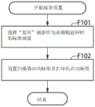
Fig. 10 is a flowchart illustrating a control method of the image forming apparatus 1 according to the present exemplary embodiment. This example is an example of the label setting process of the controller 3 in the image forming apparatus 1.
During the above-described return from sleep, the user turns on the standard screen setting, and selects the "copy" key 861 (S104). Then, in step F101, the CPU201 sets the standard screen as the "copy" screen. In step F102, the CPU201 sets a scanner start tag and a printer start tag used by the "copy" function in the registers of the interrupt controller 210. This process may be performed only once.
Fig. 11 is a flowchart illustrating a control method of the image forming apparatus 1 according to the present exemplary embodiment. This example is a process in which the controller 3 returns from sleep in the image forming apparatus 1.
In step F501, when the CPU201 detects that the user does not operate the image forming apparatus 1 for a predetermined period of time by pressing the power saving key 809 or using a timer, the backlight of the LCD touch panel 800 is turned off, and the image forming apparatus 1 is put into a sleep mode (step S105). In step F502, the CPU201 determines whether the image forming apparatus 1 has received a factor serving as a return request from sleep, such as pressing of the power saving key 809 by the user or detection by a sensor. If the image forming apparatus 1 receives the return from sleep factor (yes in step F502), the CPU201 starts the return from sleep process. Then, the process advances to step F503.
In step F503, the CPU201 determines whether the factor of return from sleep is a return factor for opening the UI panel on the operation unit 5 (e.g., pressing the power saving key 809, detection of a sensor, or receiving data).
If the CPU201 determines that the factor of returning from sleep is a return factor for opening the UI panel due to the request to cancel the power saving state by the key operation (yes in step F503), then in step F504, the CPU201 determines whether the printer start tag is set in the register of the interrupt controller 210. If the CPU201 determines that the return from sleep factor is not the return factor for opening the UI panel (no in step F503), the processing proceeds to step F508. If the CPU201 determines that the printer activation tag is set (yes in step F504), then in step F505, the CPU201 cancels the operation wait signal of the printer device 4. In the present exemplary embodiment, the printer activation tag is set (yes in step F504), and therefore the CPU201 cancels the operation wait signal of the printer device 4. If the CPU201 determines that the printer activation tag is not set (no in step F504), the processing proceeds to step F506.
Meanwhile, in step F506, the CPU201 synchronously determines whether or not a scanner start flag is set in the register of the interrupt controller 210. If the CPU201 determines that the scanner start flag is set (yes in step F506), then in step F507, the CPU201 cancels the operation wait signal of the scanner device 2. In the present exemplary embodiment, the scanner start flag is set (yes in step F506), and therefore the CPU201 cancels the operation wait signal of the scanner device 2.
If the CPU201 determines that the scanner activation flag is not set (no in step F506), then in step F508, the CPU201 powers on the printer apparatus 4 and the scanner apparatus 2. In step F509, the CPU201 returns the image forming apparatus 1 from sleep. In the present exemplary embodiment, the CPU201 energizes the printer apparatus 4 and the scanner apparatus 2 in the operation waiting cancellation state to perform operations such as home position detection for motor driving, sheet detection in a cassette section for motor driving, and rotation of the polygon mirror.
According to the present exemplary embodiment, when "copying" is performed upon returning from sleep (S107), since the image forming apparatus 1 energizes the printer device 4 and the scanner device 2 in the operation wait cancellation state upon returning from sleep, the time period elapsed before completion of printing can be shortened.
On the other hand, when an operation other than "copy" is performed upon returning from sleep, since the image forming apparatus 1 energizes the printer device 4 and the scanner device 2 in the operation wait cancellation state during returning from sleep, the time period elapsed before completion of printing can be shortened as much as possible.
In the present exemplary embodiment, the process of returning from sleep in the power-off state of the printer device 4 and the scanner device 2 is described.
However, the image forming apparatus 1 can return from the sleep in the power-on state of the printer device 4 and the scanner device 2. In this case, the printer apparatus 4 and the scanner apparatus 2 do not change in the state when powered on in step F508. However, when the operation wait signal is canceled in each of step F505 and step F507, the initialization process is executed. Therefore, although detailed description thereof is omitted, effects similar to those in the first exemplary embodiment can be obtained.
The second exemplary embodiment is characterized in that: when the "scan and store" screen is set as the standard screen, the operation wait is canceled only for the scan function.
A second exemplary embodiment will be described below with reference to fig. 11, 12, and 13.
Fig. 12 is a timing chart illustrating a power supply state of the image forming apparatus 1 according to the present exemplary embodiment. This example corresponds to the power-on states of the printer device 4 and the scanner device 2 illustrated in fig. 1.
In fig. 12, the X axis represents time, and the Y axis represents power-on of the printer apparatus 4 and the scanner apparatus 2 and execution of a job. Fig. 12 is substantially the same as fig. 9 described in the first exemplary embodiment, and thus the description thereof is not repeated.
Fig. 13 is a flowchart illustrating a control method of the image forming apparatus 1 according to the present exemplary embodiment. This example is a label setting process of the controller 3 in the image forming apparatus 1.
The user turns on the standard screen setting during the above-described return from sleep, and selects the "scan and store" key 862 (S204). Then, in step F201, the CPU201 sets the standard screen during the return from sleep as the "scan and store" screen. In step F202, the CPU201 sets a scanner start flag used by the "scan and store" function in a register of the interrupt controller 210. This process may be performed only once.
The return from sleep process in the present exemplary embodiment will be described below with reference to fig. 11.
In step F501, when the CPU201 detects that the user has not operated the image forming apparatus 1 for a predetermined period of time by pressing the power saving key 809 or using a timer (step S205), the backlight of the LCD touch panel 800 is turned off, and the image forming apparatus 1 is put into the sleep mode.
Then, in step F502, the CPU201 determines whether the image forming apparatus 1 has received a factor of returning from sleep such as pressing of the power saving key 809 by the user (step S206) or detection of a sensor. If the image forming apparatus 1 receives the return from sleep factor (yes in step F502), the CPU201 starts the return from sleep process. Then, the process advances to step F503. In step F503, the CPU201 determines whether the factor of returning from sleep is a return factor for opening the UI panel on the operation unit 5 (e.g., detection of pressing the power saving key 809 or a sensor).
If the CPU201 determines that the return from sleep factor is the return factor for opening the UI panel (yes in step F503), in step F504, the CPU201 determines whether the printer start tag is set in the register of the interrupt controller 210. If the CPU201 determines that the return from sleep factor is not the return factor for opening the UI panel (no in step F503), the processing proceeds to step F508. If the CPU201 determines that the printer activation tag is set (yes in step F504), in step F505, the CPU201 cancels the operation wait signal of the printer device 4. In the present exemplary embodiment, the printer activation tag is not set (no in step F504), and therefore the CPU201 does not cancel the operation wait signal of the printer device 4.
If the CPU201 determines that the printer start flag is not set (no in step F504), in step F506, the CPU201 synchronously determines whether the scanner start flag is set in the register of the interrupt controller 210.
If the CPU201 determines that the scanner start flag is set (yes in step F506), then in step F507, the CPU201 cancels the operation wait signal of the scanner device 2. In the present exemplary embodiment, the scanner start flag is set (yes in step F506), and therefore the CPU201 cancels the operation wait signal of the scanner device 2.
If the CPU201 determines that the scanner activation flag is not set (no in step F506), then in step F508, the CPU201 powers on the printer apparatus 4 and the scanner apparatus 2. In step F509, the CPU201 returns the image forming apparatus 1 from sleep. In the present exemplary embodiment, the CPU201 energizes only the scanner device 2 in the operation waiting cancellation state to perform an operation such as home position detection for motor driving.
According to the present exemplary embodiment, when "scan and store" is performed during the return from sleep (S207), since the image forming apparatus 1 powers on the scanner device 2 in the operation wait cancellation state during the return from sleep, the period of time that elapses before the scanner device 2 completes scanning can be shortened.
On the other hand, when an operation other than "scan and store" is performed upon returning from sleep, since the image forming apparatus 1 energizes the scanner device 2 in the operation waiting state during returning from sleep, the time period elapsed before completion of printing can be made as short as possible.
Even if the "scan and store" key 862 is not selected but a function such as the "scan and send" key 864 which uses only the scanner without using the printer is selected on the initial screen illustrated in fig. 3, the flow in the present exemplary embodiment can be used. However, the contents of the control procedure when the "scan and send" key 864 is selected are overlapped with the contents of the control procedure when the "scan and store" key 862 is selected, and thus the description thereof is not repeated.
In the third exemplary embodiment, when the "print stored original" screen is set as the standard screen, the operation is canceled waiting only for the printer.
A third exemplary embodiment will be described below with reference to fig. 11, 14, and 15.
Fig. 14 is a timing chart illustrating a power supply state of the image forming apparatus 1 according to the present exemplary embodiment. This example corresponds to the power-on states of the printer device 4 and the scanner device 2 illustrated in fig. 1.
In fig. 14, the X axis represents time, and the Y axis represents power-on of the printer apparatus 4 and the scanner apparatus 2 and execution of a job. Fig. 14 is substantially the same as fig. 9 described in the first exemplary embodiment, and thus the description thereof is not repeated.
Fig. 15 is a flowchart illustrating a control method of the image forming apparatus 1 according to the present exemplary embodiment. This example is a label setting process of the controller 3 in the image forming apparatus 1.
The user opens the standard screen during the return from sleep described above, and selects the "print stored original" key 863 (S304). Then, in step F301, the CPU201 sets the standard screen during the return from sleep as a "print stored original" screen. In step F302, the CPU201 sets a printer start label used by the "print stored original" function in a register of the interrupt controller 210. This process may be performed only once. The process of returning from sleep in the present exemplary embodiment will be described below with respect to a flowchart illustrated in fig. 11.
In step F501, the CPU201 turns off the backlight of the LCD touch panel 800 by pressing the power saving key 809 or using a timer to detect that the user has not operated the image forming apparatus 1 for a predetermined period of time (S305), and brings the image forming apparatus 1 into the sleep mode. Then in step F502, the CPU201 determines whether the image forming apparatus 1 has received a return from sleep factor such as detection of the user pressing the power saving key 809 or a sensor. If the image forming apparatus 1 receives the return from sleep factor (yes in step F502), the CPU201 starts the return from sleep process. Then, the process advances to step F503.
In step F503, the CPU201 determines whether the factor of returning from sleep is a return factor for opening the UI panel on the operation unit 5 (e.g., detection of pressing the power saving key 809 or a sensor).
If the CPU201 determines that the factor of returning from sleep is the return factor for opening the UI panel (yes in step F503), then in step F504, the CPU201 determines whether the printer start tag is set in the register of the interrupt controller 210. If the CPU201 determines that the return from sleep factor is not the return factor for opening the UI panel (no in step F503), the processing proceeds to step F508.
On the other hand, if the CPU201 determines that the printer activation tag is set (yes in step F504), in step F505, the CPU201 cancels the operation wait signal of the printer device 4. In the present exemplary embodiment, the printer activation tag is set (no in step F504), and therefore the CPU201 cancels the operation wait signal of the printer device 4. If the CPU201 determines that the printer start flag is not set (no in step F504), in step F506, the CPU201 synchronously determines whether the scanner start flag is set in the register of the interrupt controller 210.
If the CPU201 determines that the scanner start flag is set (yes in step F506), in step F507, the CPU201 cancels the operation wait signal of the scanner device 2. In the present exemplary embodiment, the scanner start flag is not set (yes in step F506), and therefore the CPU201 does not cancel the operation wait signal of the scanner device 2.
If the CPU201 determines that the scanner activation flag is not set (no in step F506), in step F508, the CPU201 powers on the printer apparatus 4 and the scanner apparatus 2. In step F509, the CPU201 returns the image forming apparatus 1 from sleep. In the present exemplary embodiment, the CPU201 energizes only the printer apparatus 4 in the operation waiting cancellation state to perform initialization operations such as sheet detection in a cassette section for motor driving and rotation of a polygon mirror.
According to the present exemplary embodiment, when "printing the stored original" is executed upon return from sleep (S307), since the image forming apparatus 1 powers on the printer device 4 in the operation wait cancellation state during return from sleep, the time period elapsed before the image forming apparatus 1 completes printing can be shortened.
On the other hand, when an operation other than "print stored original" is performed upon return from sleep, since the image forming apparatus 1 energizes the printer device 4 in the operation waiting state during return from sleep, the image forming apparatus 1 is enabled to be started silently while being enabled to finish printing early.
The flow in the present exemplary embodiment can be used not only in "printing stored documents", but also in similar operations such as printing of reports, which do not use a scanner but use only a printer. However, the content of the operation is repeated with that of the operation using both the scanner and the printer, and thus the description thereof is not repeated.
Other embodiments
The embodiments of the present invention can also be realized by a method in which software (programs) that perform the functions of the above-described embodiments are supplied to a system or an apparatus through a network or various storage media, and a computer or a Central Processing Unit (CPU), a Micro Processing Unit (MPU) of the system or the apparatus reads out and executes the methods of the programs.
While the present invention has been described with reference to exemplary embodiments, it is to be understood that the invention is not limited to the disclosed exemplary embodiments. The scope of the claims is to be accorded the broadest interpretation so as to encompass all such modifications and equivalent structures and functions.
Claims (24)
1. An image forming apparatus capable of shifting to a power saving state, the image forming apparatus comprising:
a printing unit configured to execute a printing process;
a display;
a selection unit configured to select an initial screen to be displayed when the image forming apparatus returns from a power saving state in accordance with a user selection;
a storage unit configured to store information corresponding to the initial screen selected by the selection unit;
a print control unit configured to perform a specific operation including configuring driving of at least one motor in the print unit, an
A signal output unit configured to:
(A) outputting an operation wait signal to the print control unit and turning on the printing unit in accordance with a return instruction to return the image forming apparatus in a case where the information corresponding to the initial screen stored in the storage unit corresponds to a screen unrelated to a print function,
(B) turning on the printing unit without outputting an operation wait signal to the printing control unit according to a return instruction to return the image forming apparatus in a case where the information corresponding to the initial screen stored in the storage unit corresponds to a screen related to a printing function,
wherein the print control unit does not perform a specific operation in a case where an operation waiting signal is input.
2. The image forming apparatus according to claim 1, wherein the at least one motor is one of a motor for rotating a polygon mirror, a motor for conveying a sheet, a motor for rotating a fan, and a motor for rotating a drum.
3. The image forming apparatus according to claim 1, further comprising:
a reading unit configured to perform a reading process,
a reading control unit configured to control in accordance with the return instruction so as to perform a specific operation including driving of at least one motor configured in the reading unit based on another predetermined information stored in the storage unit.
4. The image forming apparatus according to claim 3, wherein the motor provided in the reading unit is one of a motor for moving the reading head and a motor for conveying the original.
5. The image forming apparatus according to claim 1, the display displaying a setting screen for selecting the initial screen.
6. The image forming apparatus according to claim 1, wherein the storage unit stores predetermined information in a case where the initial screen selected by the selection unit is a copy screen or a print stored original screen.
7. The image forming apparatus according to claim 3, wherein the storage unit stores the other predetermined information in a case where the initial screen selected by the selection unit is a copy screen, a scan and store screen, or a scan and transmit screen.
8. The image forming apparatus according to claim 1, wherein the storage unit stores information corresponding to the initial screen selected by the selection unit when the selection unit selects the initial screen.
9. The image forming apparatus according to claim 1, wherein the storage unit stores the information in a register of the signal output unit.
10. The image forming apparatus according to claim 1, further comprising:
a power supply unit configured to supply power to the motor; and
a switch disposed between the power supply unit and the motor,
wherein the signal output unit is configured to open the switch according to the return instruction.
11. The image forming apparatus according to claim 1, wherein power is not supplied to the storage unit in a power saving state.
12. An image forming apparatus capable of shifting to a power saving state, the image forming apparatus comprising:
a reading unit configured to perform a reading process;
a display;
a selection unit configured to select an initial screen to be displayed when the image forming apparatus returns from a power saving state in accordance with a user selection;
a storage unit configured to store information corresponding to the initial screen selected by the selection unit; and
a reading control unit configured to perform a specific operation including configuring driving of at least one motor in the reading unit, and
a signal output unit configured to:
(A) outputting an operation wait signal to the reading control unit and turning on the reading unit in accordance with a return instruction to return the image forming apparatus in a case where the information corresponding to the initial picture stored in the storage unit corresponds to a picture irrelevant to the scanning function,
(B) turning on the reading unit without outputting an operation wait signal to the reading control unit in accordance with a return instruction to return the image forming apparatus in a case where the information corresponding to the initial screen stored in the storage unit corresponds to a screen related to a scanning function,
wherein the read control unit does not perform a specific operation in a case where an operation waiting signal is input.
13. The image forming apparatus according to claim 12, wherein the motor provided in the reading unit is one of a motor for moving the reading head and a motor for conveying the original.
14. The image forming apparatus according to claim 12, further comprising:
a printing unit configured to execute a printing process;
a printing control unit configured to control in accordance with the return instruction so as to perform a specific operation including driving of at least one motor configured in the printing unit based on another predetermined information stored in the memory.
15. The image forming apparatus according to claim 14, wherein the motor configured in the printing unit is one of a motor for rotating the polygon mirror, a motor for conveying the sheet, a motor for rotating the fan, and a motor for rotating the drum.
16. The image forming apparatus according to claim 12, wherein the display displays a setting screen for selecting the initial screen.
17. The image forming apparatus according to claim 12, wherein the storage unit stores the predetermined information in a case where the initial screen selected by the selection unit is a copy screen, a scan and store screen, or a scan and transmit screen.
18. The image forming apparatus according to claim 14, wherein the storage unit stores the other predetermined information in a case where the initial screen selected by the selection unit is a copy screen or a print stored original screen.
19. The image forming apparatus according to claim 12, wherein the storage unit stores information corresponding to the initial screen selected by the selection unit when the selection unit selects the initial screen.
20. The image forming apparatus according to claim 12, wherein the storage unit stores the information in a register of the signal output unit.
21. The image forming apparatus according to claim 12, further comprising:
a power supply unit configured to supply power to the motor; and
a switch disposed between the power supply unit and the motor,
wherein the signal output unit is configured to open the switch according to the return instruction.
22. An image forming apparatus according to claim 12, wherein power is not supplied to the storage unit in a power saving state.
23. A method for controlling an image forming apparatus that is capable of shifting to a power saving state and has a printing unit configured to execute a printing process and a print control unit, the method comprising:
selecting an initial screen to be displayed when the image forming apparatus returns from a power saving state in accordance with a user selection;
storing information corresponding to the selected initial picture; and
performing a specific operation including configuring driving of at least one motor in the printing unit, an
(A) Outputting an operation wait signal to the print control unit and turning on the printing unit in accordance with a return instruction to return the image forming apparatus in a case where the stored information corresponding to the initial screen corresponds to a screen unrelated to a print function,
(B) turning on the printing unit without outputting an operation wait signal to the print control unit in accordance with a return instruction to return the image forming apparatus in a case where the stored information corresponding to the initial screen corresponds to a screen related to a print function,
wherein the print control unit does not perform a specific operation in a case where an operation waiting signal is input.
24. A method for controlling an image forming apparatus that is capable of shifting to a power saving state and has a reading unit configured to execute a reading process and a reading control unit, the method comprising:
selecting an initial screen to be displayed when the image forming apparatus returns from the power saving state, in accordance with a user selection;
storing information corresponding to the selected initial picture; and
performing a specific operation including configuring a drive of at least one motor in the reading unit, an
(A) Outputting an operation wait signal to the reading control unit and turning on the reading unit in accordance with a return instruction to return the image forming apparatus in a case where the stored information corresponding to the initial picture corresponds to a picture irrelevant to the scanning function,
(B) turning on the reading unit without outputting an operation wait signal to the reading control unit in accordance with a return instruction to return the image forming apparatus in a case where the stored information corresponding to the initial screen corresponds to a screen related to a scan function,
wherein the read control unit does not perform a specific operation in a case where an operation waiting signal is input.
Applications Claiming Priority (3)
| Application Number | Priority Date | Filing Date | Title |
|---|---|---|---|
| JP2014-107238 | 2014-05-23 | ||
| JP2014107238A JP6860279B2 (en) | 2014-05-23 | 2014-05-23 | Image forming apparatus and control method of image forming apparatus |
| CN201510257111.5A CN105100535B (en) | 2014-05-23 | 2015-05-19 | The control method of image forming apparatus and image forming apparatus |
Related Parent Applications (1)
| Application Number | Title | Priority Date | Filing Date |
|---|---|---|---|
| CN201510257111.5A Division CN105100535B (en) | 2014-05-23 | 2015-05-19 | The control method of image forming apparatus and image forming apparatus |
Publications (2)
| Publication Number | Publication Date |
|---|---|
| CN110035196A CN110035196A (en) | 2019-07-19 |
| CN110035196B true CN110035196B (en) | 2021-12-03 |
Family
ID=54556955
Family Applications (2)
| Application Number | Title | Priority Date | Filing Date |
|---|---|---|---|
| CN201910216380.5A Active CN110035196B (en) | 2014-05-23 | 2015-05-19 | Image forming apparatus and control method of image forming apparatus |
| CN201510257111.5A Active CN105100535B (en) | 2014-05-23 | 2015-05-19 | The control method of image forming apparatus and image forming apparatus |
Family Applications After (1)
| Application Number | Title | Priority Date | Filing Date |
|---|---|---|---|
| CN201510257111.5A Active CN105100535B (en) | 2014-05-23 | 2015-05-19 | The control method of image forming apparatus and image forming apparatus |
Country Status (3)
| Country | Link |
|---|---|
| US (2) | US9961223B2 (en) |
| JP (1) | JP6860279B2 (en) |
| CN (2) | CN110035196B (en) |
Families Citing this family (8)
| Publication number | Priority date | Publication date | Assignee | Title |
|---|---|---|---|---|
| JP6425490B2 (en) * | 2014-10-09 | 2018-11-21 | キヤノン株式会社 | Image forming apparatus, control method and program |
| JP5939348B2 (en) * | 2015-11-13 | 2016-06-22 | 株式会社三洋物産 | Game machine |
| JP5939347B2 (en) * | 2015-11-13 | 2016-06-22 | 株式会社三洋物産 | Game machine |
| JP6703790B2 (en) * | 2016-08-05 | 2020-06-03 | キヤノン株式会社 | Information processing apparatus, control method thereof, and program |
| JP6859819B2 (en) * | 2017-04-12 | 2021-04-14 | 富士ゼロックス株式会社 | Detection device and image forming device |
| JP7080595B2 (en) * | 2017-07-14 | 2022-06-06 | キヤノン株式会社 | Information processing equipment, its control method, and programs |
| CN108944093A (en) * | 2018-06-27 | 2018-12-07 | 阜阳市易邦办公设备销售有限公司 | A kind of control method for printer |
| US10908855B1 (en) * | 2019-09-11 | 2021-02-02 | Toshiba Tec Kabushiki Kaisha | Image forming apparatus with power saving mode |
Citations (4)
| Publication number | Priority date | Publication date | Assignee | Title |
|---|---|---|---|---|
| US5745247A (en) * | 1994-01-28 | 1998-04-28 | Ricoh Company, Ltd. | Image forming apparatus having a controlled fixing unit |
| CN101856915A (en) * | 2009-04-07 | 2010-10-13 | 沈阳飞捷激光科技有限公司 | Automatic feeding control device of laser printing sign and control method thereof |
| CN102595008A (en) * | 2011-01-14 | 2012-07-18 | 富士施乐株式会社 | Image forming apparatus and image forming method |
| JP2012191369A (en) * | 2011-03-10 | 2012-10-04 | Canon Inc | Image forming apparatus |
Family Cites Families (10)
| Publication number | Priority date | Publication date | Assignee | Title |
|---|---|---|---|---|
| JP2000295440A (en) * | 1999-04-09 | 2000-10-20 | Canon Electronics Inc | Image reader, image processing system, operation control method and storage medium |
| JP4157820B2 (en) * | 2002-12-27 | 2008-10-01 | 株式会社リコー | Image forming apparatus |
| US7567366B2 (en) * | 2003-05-29 | 2009-07-28 | Seiko Epson Corporation | Image scanner provided with power saving mode and a system having a power saving mode |
| JP5495542B2 (en) * | 2008-12-11 | 2014-05-21 | キヤノン株式会社 | Image processing system, image processing apparatus, and image processing method |
| US20100202018A1 (en) * | 2009-02-09 | 2010-08-12 | Kabushiki Kaisha Toshiba | Image forming apparatus, power-saving control method, and computer-readable recording medium having recorded therein power-saving control program |
| JP5764930B2 (en) * | 2011-01-13 | 2015-08-19 | 富士ゼロックス株式会社 | Image forming apparatus and program |
| JP5742274B2 (en) * | 2011-02-15 | 2015-07-01 | 株式会社リコー | Image forming apparatus, image forming control method, image forming control program, and recording medium |
| JP5516497B2 (en) * | 2011-04-28 | 2014-06-11 | ブラザー工業株式会社 | Image forming apparatus and image reading apparatus |
| JP2013172240A (en) * | 2012-02-20 | 2013-09-02 | Seiko Epson Corp | Function limit release system of electronic device, function limit release method of electronic device and electronic device |
| JP2013258474A (en) * | 2012-06-11 | 2013-12-26 | Canon Inc | Image forming apparatus and control method of the same, and program |
-
2014
- 2014-05-23 JP JP2014107238A patent/JP6860279B2/en active Active
-
2015
- 2015-05-19 CN CN201910216380.5A patent/CN110035196B/en active Active
- 2015-05-19 CN CN201510257111.5A patent/CN105100535B/en active Active
- 2015-05-21 US US14/719,165 patent/US9961223B2/en active Active
-
2018
- 2018-03-05 US US15/912,198 patent/US10484563B2/en active Active
Patent Citations (4)
| Publication number | Priority date | Publication date | Assignee | Title |
|---|---|---|---|---|
| US5745247A (en) * | 1994-01-28 | 1998-04-28 | Ricoh Company, Ltd. | Image forming apparatus having a controlled fixing unit |
| CN101856915A (en) * | 2009-04-07 | 2010-10-13 | 沈阳飞捷激光科技有限公司 | Automatic feeding control device of laser printing sign and control method thereof |
| CN102595008A (en) * | 2011-01-14 | 2012-07-18 | 富士施乐株式会社 | Image forming apparatus and image forming method |
| JP2012191369A (en) * | 2011-03-10 | 2012-10-04 | Canon Inc | Image forming apparatus |
Also Published As
| Publication number | Publication date |
|---|---|
| CN105100535A (en) | 2015-11-25 |
| CN110035196A (en) | 2019-07-19 |
| JP2015222909A (en) | 2015-12-10 |
| US20150341516A1 (en) | 2015-11-26 |
| US20180198940A1 (en) | 2018-07-12 |
| JP6860279B2 (en) | 2021-04-14 |
| US9961223B2 (en) | 2018-05-01 |
| CN105100535B (en) | 2019-04-05 |
| US10484563B2 (en) | 2019-11-19 |
Similar Documents
| Publication | Publication Date | Title |
|---|---|---|
| CN110035196B (en) | Image forming apparatus and control method of image forming apparatus | |
| US10110764B2 (en) | Image forming apparatus that shifts into different power saving states and control method thereof | |
| US11307633B2 (en) | Information processing apparatus, control method thereof, and storage medium | |
| US10466752B2 (en) | Information processing apparatus that offers chance of eliminating hang-up state, control method therefor, and storage medium | |
| US9049321B2 (en) | Image forming apparatus in which time taken to return from sleep state is reduced, method of controlling image forming apparatus, and storage medium | |
| US9143645B2 (en) | Image processing apparatus for remotely managing a power source, method for controlling the same, and a storage medium | |
| US10447878B2 (en) | Image forming apparatus, method for controlling image forming apparatus, and storage medium | |
| US20150098104A1 (en) | Setting power savings modes based on ambient light and user set time periods | |
| US20100165806A1 (en) | Information processing apparatus, information processing apparatus control method, and storage medium | |
| KR101684229B1 (en) | Image forming apparatus, method for controlling the same, recording medium, and image forming system | |
| JP2016015696A (en) | Image forming apparatus, control method of image forming apparatus, and program | |
| JP2007136930A (en) | Image processing mode operating device and image forming device | |
| JP2018025943A (en) | Image forming apparatus, control method and program thereof | |
| JP2007026309A (en) | Image forming device and control method thereof | |
| JP2017177456A (en) | Power control method for image forming apparatus | |
| US10228645B2 (en) | Image forming apparatus, power control method of image forming apparatus, and storage medium | |
| US9769344B2 (en) | Information processing apparatus that controls display of display unit, and control method therefor and storage medium | |
| US11539851B2 (en) | Apparatus for switching a power state among a plurality of power states and method thereof | |
| US20240015256A1 (en) | Image forming apparatus, method for controlling image forming apparatus | |
| JP2024047696A (en) | Image forming device, and method of controlling image forming device | |
| JP5808136B2 (en) | Image forming apparatus, control method thereof, and program | |
| JP2002033865A (en) | Image input device and image output device |
Legal Events
| Date | Code | Title | Description |
|---|---|---|---|
| PB01 | Publication | ||
| PB01 | Publication | ||
| SE01 | Entry into force of request for substantive examination | ||
| SE01 | Entry into force of request for substantive examination | ||
| GR01 | Patent grant | ||
| GR01 | Patent grant |