JP6425490B2 - Image forming apparatus, control method and program - Google Patents
Image forming apparatus, control method and program Download PDFInfo
- Publication number
- JP6425490B2 JP6425490B2 JP2014208340A JP2014208340A JP6425490B2 JP 6425490 B2 JP6425490 B2 JP 6425490B2 JP 2014208340 A JP2014208340 A JP 2014208340A JP 2014208340 A JP2014208340 A JP 2014208340A JP 6425490 B2 JP6425490 B2 JP 6425490B2
- Authority
- JP
- Japan
- Prior art keywords
- power
- image forming
- forming apparatus
- state
- function
- Prior art date
- Legal status (The legal status is an assumption and is not a legal conclusion. Google has not performed a legal analysis and makes no representation as to the accuracy of the status listed.)
- Active
Links
- 238000000034 method Methods 0.000 title description 31
- 230000006870 function Effects 0.000 claims description 174
- 238000004891 communication Methods 0.000 claims description 56
- 238000012545 processing Methods 0.000 claims description 55
- 230000004044 response Effects 0.000 claims description 27
- 230000005540 biological transmission Effects 0.000 claims description 21
- 230000008859 change Effects 0.000 claims description 13
- 238000003860 storage Methods 0.000 claims description 12
- 238000004458 analytical method Methods 0.000 claims description 6
- 230000000977 initiatory effect Effects 0.000 claims description 3
- 238000003672 processing method Methods 0.000 claims 1
- 238000012423 maintenance Methods 0.000 description 40
- 230000007704 transition Effects 0.000 description 39
- 230000008569 process Effects 0.000 description 24
- 238000010586 diagram Methods 0.000 description 17
- 238000011084 recovery Methods 0.000 description 13
- 238000012544 monitoring process Methods 0.000 description 6
- 238000001514 detection method Methods 0.000 description 4
- 238000012546 transfer Methods 0.000 description 3
- 230000004913 activation Effects 0.000 description 2
- 238000012790 confirmation Methods 0.000 description 2
- 230000000694 effects Effects 0.000 description 2
- 230000002093 peripheral effect Effects 0.000 description 2
- 238000003825 pressing Methods 0.000 description 2
- 238000005316 response function Methods 0.000 description 2
- 230000015572 biosynthetic process Effects 0.000 description 1
- 238000006243 chemical reaction Methods 0.000 description 1
- 238000005520 cutting process Methods 0.000 description 1
- 230000003111 delayed effect Effects 0.000 description 1
- 238000007730 finishing process Methods 0.000 description 1
- 238000010438 heat treatment Methods 0.000 description 1
- 238000003780 insertion Methods 0.000 description 1
- 230000037431 insertion Effects 0.000 description 1
- 238000007562 laser obscuration time method Methods 0.000 description 1
- 238000005259 measurement Methods 0.000 description 1
- 230000000737 periodic effect Effects 0.000 description 1
- 238000004080 punching Methods 0.000 description 1
- 239000004065 semiconductor Substances 0.000 description 1
- 239000007787 solid Substances 0.000 description 1
- 238000012800 visualization Methods 0.000 description 1
Images


Classifications
-
- H—ELECTRICITY
- H04—ELECTRIC COMMUNICATION TECHNIQUE
- H04N—PICTORIAL COMMUNICATION, e.g. TELEVISION
- H04N1/00—Scanning, transmission or reproduction of documents or the like, e.g. facsimile transmission; Details thereof
- H04N1/00885—Power supply means, e.g. arrangements for the control of power supply to the apparatus or components thereof
- H04N1/00888—Control thereof
- H04N1/00891—Switching on or off, e.g. for saving power when not in use
-
- H—ELECTRICITY
- H04—ELECTRIC COMMUNICATION TECHNIQUE
- H04N—PICTORIAL COMMUNICATION, e.g. TELEVISION
- H04N1/00—Scanning, transmission or reproduction of documents or the like, e.g. facsimile transmission; Details thereof
- H04N1/00885—Power supply means, e.g. arrangements for the control of power supply to the apparatus or components thereof
- H04N1/00888—Control thereof
- H04N1/00896—Control thereof using a low-power mode, e.g. standby
-
- G—PHYSICS
- G06—COMPUTING; CALCULATING OR COUNTING
- G06F—ELECTRIC DIGITAL DATA PROCESSING
- G06F1/00—Details not covered by groups G06F3/00 - G06F13/00 and G06F21/00
- G06F1/26—Power supply means, e.g. regulation thereof
- G06F1/32—Means for saving power
- G06F1/3203—Power management, i.e. event-based initiation of a power-saving mode
- G06F1/3206—Monitoring of events, devices or parameters that trigger a change in power modality
- G06F1/3209—Monitoring remote activity, e.g. over telephone lines or network connections
-
- G—PHYSICS
- G06—COMPUTING; CALCULATING OR COUNTING
- G06F—ELECTRIC DIGITAL DATA PROCESSING
- G06F1/00—Details not covered by groups G06F3/00 - G06F13/00 and G06F21/00
- G06F1/26—Power supply means, e.g. regulation thereof
- G06F1/32—Means for saving power
- G06F1/3203—Power management, i.e. event-based initiation of a power-saving mode
- G06F1/3206—Monitoring of events, devices or parameters that trigger a change in power modality
- G06F1/3215—Monitoring of peripheral devices
-
- G—PHYSICS
- G06—COMPUTING; CALCULATING OR COUNTING
- G06F—ELECTRIC DIGITAL DATA PROCESSING
- G06F1/00—Details not covered by groups G06F3/00 - G06F13/00 and G06F21/00
- G06F1/26—Power supply means, e.g. regulation thereof
- G06F1/32—Means for saving power
- G06F1/3203—Power management, i.e. event-based initiation of a power-saving mode
- G06F1/3234—Power saving characterised by the action undertaken
- G06F1/325—Power saving in peripheral device
- G06F1/3284—Power saving in printer
-
- G—PHYSICS
- G06—COMPUTING; CALCULATING OR COUNTING
- G06F—ELECTRIC DIGITAL DATA PROCESSING
- G06F1/00—Details not covered by groups G06F3/00 - G06F13/00 and G06F21/00
- G06F1/26—Power supply means, e.g. regulation thereof
- G06F1/32—Means for saving power
- G06F1/3203—Power management, i.e. event-based initiation of a power-saving mode
- G06F1/3234—Power saving characterised by the action undertaken
- G06F1/3287—Power saving characterised by the action undertaken by switching off individual functional units in the computer system
-
- H—ELECTRICITY
- H04—ELECTRIC COMMUNICATION TECHNIQUE
- H04N—PICTORIAL COMMUNICATION, e.g. TELEVISION
- H04N1/00—Scanning, transmission or reproduction of documents or the like, e.g. facsimile transmission; Details thereof
- H04N1/00127—Connection or combination of a still picture apparatus with another apparatus, e.g. for storage, processing or transmission of still picture signals or of information associated with a still picture
- H04N1/00204—Connection or combination of a still picture apparatus with another apparatus, e.g. for storage, processing or transmission of still picture signals or of information associated with a still picture with a digital computer or a digital computer system, e.g. an internet server
- H04N1/00209—Transmitting or receiving image data, e.g. facsimile data, via a computer, e.g. using e-mail, a computer network, the internet, I-fax
- H04N1/00214—Transmitting or receiving image data, e.g. facsimile data, via a computer, e.g. using e-mail, a computer network, the internet, I-fax details of transmission
- H04N1/0022—Transmitting or receiving image data, e.g. facsimile data, via a computer, e.g. using e-mail, a computer network, the internet, I-fax details of transmission involving facsimile protocols or a combination of facsimile protocols and computer data transmission protocols
-
- H—ELECTRICITY
- H04—ELECTRIC COMMUNICATION TECHNIQUE
- H04N—PICTORIAL COMMUNICATION, e.g. TELEVISION
- H04N1/00—Scanning, transmission or reproduction of documents or the like, e.g. facsimile transmission; Details thereof
- H04N1/00127—Connection or combination of a still picture apparatus with another apparatus, e.g. for storage, processing or transmission of still picture signals or of information associated with a still picture
- H04N1/00344—Connection or combination of a still picture apparatus with another apparatus, e.g. for storage, processing or transmission of still picture signals or of information associated with a still picture with a management, maintenance, service or repair apparatus
-
- H—ELECTRICITY
- H04—ELECTRIC COMMUNICATION TECHNIQUE
- H04N—PICTORIAL COMMUNICATION, e.g. TELEVISION
- H04N1/00—Scanning, transmission or reproduction of documents or the like, e.g. facsimile transmission; Details thereof
- H04N1/00885—Power supply means, e.g. arrangements for the control of power supply to the apparatus or components thereof
- H04N1/00904—Arrangements for supplying power to different circuits or for supplying power at different levels
-
- H—ELECTRICITY
- H04—ELECTRIC COMMUNICATION TECHNIQUE
- H04N—PICTORIAL COMMUNICATION, e.g. TELEVISION
- H04N1/00—Scanning, transmission or reproduction of documents or the like, e.g. facsimile transmission; Details thereof
- H04N1/32—Circuits or arrangements for control or supervision between transmitter and receiver or between image input and image output device, e.g. between a still-image camera and its memory or between a still-image camera and a printer device
- H04N1/32037—Automation of particular transmitter jobs, e.g. multi-address calling, auto-dialing
- H04N1/32064—Multi-address calling
- H04N1/32069—Multi-address calling simultaneously to a plurality of destinations, e.g. multi-casting
-
- H—ELECTRICITY
- H04—ELECTRIC COMMUNICATION TECHNIQUE
- H04N—PICTORIAL COMMUNICATION, e.g. TELEVISION
- H04N1/00—Scanning, transmission or reproduction of documents or the like, e.g. facsimile transmission; Details thereof
- H04N1/32—Circuits or arrangements for control or supervision between transmitter and receiver or between image input and image output device, e.g. between a still-image camera and its memory or between a still-image camera and a printer device
- H04N1/327—Initiating, continuing or ending a single-mode communication; Handshaking therefor
- H04N1/32704—Establishing a communication with one of a facsimile and another telecommunication apparatus sharing a single line
- H04N1/32739—Generating signals
- H04N1/32741—Generating ringing or calling signals or tones
-
- H—ELECTRICITY
- H04—ELECTRIC COMMUNICATION TECHNIQUE
- H04N—PICTORIAL COMMUNICATION, e.g. TELEVISION
- H04N1/00—Scanning, transmission or reproduction of documents or the like, e.g. facsimile transmission; Details thereof
- H04N1/32—Circuits or arrangements for control or supervision between transmitter and receiver or between image input and image output device, e.g. between a still-image camera and its memory or between a still-image camera and a printer device
- H04N1/333—Mode signalling or mode changing; Handshaking therefor
- H04N1/33307—Mode signalling or mode changing; Handshaking therefor prior to start of transmission, input or output of the picture signal only
- H04N1/33323—Mode signalling or mode changing; Handshaking therefor prior to start of transmission, input or output of the picture signal only transmission mode only, e.g. speed
-
- H—ELECTRICITY
- H04—ELECTRIC COMMUNICATION TECHNIQUE
- H04N—PICTORIAL COMMUNICATION, e.g. TELEVISION
- H04N1/00—Scanning, transmission or reproduction of documents or the like, e.g. facsimile transmission; Details thereof
- H04N1/32—Circuits or arrangements for control or supervision between transmitter and receiver or between image input and image output device, e.g. between a still-image camera and its memory or between a still-image camera and a printer device
- H04N1/333—Mode signalling or mode changing; Handshaking therefor
- H04N1/33346—Mode signalling or mode changing; Handshaking therefor adapting to a particular standardised protocol
-
- H—ELECTRICITY
- H04—ELECTRIC COMMUNICATION TECHNIQUE
- H04N—PICTORIAL COMMUNICATION, e.g. TELEVISION
- H04N1/00—Scanning, transmission or reproduction of documents or the like, e.g. facsimile transmission; Details thereof
- H04N1/44—Secrecy systems
- H04N1/4406—Restricting access, e.g. according to user identity
- H04N1/4413—Restricting access, e.g. according to user identity involving the use of passwords, ID codes or the like, e.g. PIN
-
- G—PHYSICS
- G06—COMPUTING; CALCULATING OR COUNTING
- G06K—GRAPHICAL DATA READING; PRESENTATION OF DATA; RECORD CARRIERS; HANDLING RECORD CARRIERS
- G06K15/00—Arrangements for producing a permanent visual presentation of the output data, e.g. computer output printers
- G06K15/40—Details not directly involved in printing, e.g. machine management, management of the arrangement as a whole or of its constitutive parts
- G06K15/4055—Managing power consumption, e.g. standby mode
-
- H—ELECTRICITY
- H04—ELECTRIC COMMUNICATION TECHNIQUE
- H04N—PICTORIAL COMMUNICATION, e.g. TELEVISION
- H04N2201/00—Indexing scheme relating to scanning, transmission or reproduction of documents or the like, and to details thereof
- H04N2201/0077—Types of the still picture apparatus
- H04N2201/0094—Multifunctional device, i.e. a device capable of all of reading, reproducing, copying, facsimile transception, file transception
-
- Y—GENERAL TAGGING OF NEW TECHNOLOGICAL DEVELOPMENTS; GENERAL TAGGING OF CROSS-SECTIONAL TECHNOLOGIES SPANNING OVER SEVERAL SECTIONS OF THE IPC; TECHNICAL SUBJECTS COVERED BY FORMER USPC CROSS-REFERENCE ART COLLECTIONS [XRACs] AND DIGESTS
- Y02—TECHNOLOGIES OR APPLICATIONS FOR MITIGATION OR ADAPTATION AGAINST CLIMATE CHANGE
- Y02D—CLIMATE CHANGE MITIGATION TECHNOLOGIES IN INFORMATION AND COMMUNICATION TECHNOLOGIES [ICT], I.E. INFORMATION AND COMMUNICATION TECHNOLOGIES AIMING AT THE REDUCTION OF THEIR OWN ENERGY USE
- Y02D10/00—Energy efficient computing, e.g. low power processors, power management or thermal management
Description
本発明は、省電力モードに遷移可能な画像形成装置、制御方法およびプログラムに関する。 The present invention relates to an image forming apparatus capable of transitioning to a power saving mode, a control method, and a program.
画像形成装置は、省エネの観点から、ユーザが一定時間操作しなかった場合などに省電力状態に移行する機能を有するのが一般的になっており、省電力状態における消費電力を低減させるための構成が種々考えられている。特許文献1に記載の画像形成装置では、スタンバイ状態のときに、画像情報の処理や記憶が可能なコントローラ部と、ネットワークに対して情報の入出力を行う入出力部とに電力が供給される。さらに、特許文献1には、省電力状態における消費電力を低減するために、省電力状態のときに、コントローラ部への電力供給が停止され、入出力部に外部装置とのデータの送受信を行わせることが記載されている。
From the viewpoint of energy saving, the image forming apparatus generally has a function of transitioning to the power saving state when the user does not operate for a certain period of time, and the like, to reduce power consumption in the power saving state. Various configurations are considered. In the image forming apparatus described in
しかしながら、特許文献1のように、省電力状態でコントローラ部への電力供給を停止すると、以下のような課題が生じることが考えられる。
However, when power supply to the controller unit is stopped in the power saving state as in
(1)応答時間の制約により生じる課題
ネットワークやファクシミリ(入出力部)は、通信相手のデバイスからの要求に対して、規定時間以内に応答を返す必要がある。例えば、画像形成装置は、SIPサーバからの要求に対して、規定時間以内に応答を返さないと、接続がキャンセルされてしまうからである。SIPサーバの種類によっては、この規定時間は、例えば4秒である。しかしながら、画像形成装置は、コントローラ部への電力供給が停止された省電力状態から復帰する場合に、数秒から数十秒の時間(スリープ復帰時間)を必要とする。ここで、画像形成装置のスリープ復帰時間が上記の規定時間より長い場合には、画像形成装置が省電力状態に移行すると、規定時間以内に通信相手のデバイスに応答を返すことができなくなってしまう。
(1) Problems arising from restriction of response time It is necessary for a network or a facsimile (input / output unit) to return a response within a specified time to a request from a device of a communication counterpart. For example, if the image forming apparatus does not respond to the request from the SIP server within a prescribed time, the connection is canceled. Depending on the type of SIP server, this prescribed time is, for example, 4 seconds. However, when recovering from the power saving state in which the power supply to the controller unit is stopped, the image forming apparatus requires a time of several seconds to several tens of seconds (sleep recovery time). Here, when the image forming apparatus sleep recovery time is longer than the specified time, when the image forming apparatus shifts to the power saving state, it becomes impossible to return a response to the device of the communication partner within the specified time. .
(2)受信機能の制約により生じる課題
特許文献1に記載の画像形成装置では、省電力状態のときに外部装置から受信したネットワーク要求に対して、省電力状態を維持したまま入出力部がネットワーク要求に対して応答を返す「代理応答機能」を有している。しかしながら、複雑なプロトコル解析、暗号認証、ユーザ入力応答、について、入出力部のハードウェアの能力では応答することができない。複雑なプロトコル解析、暗号認証およびユーザ入力応答のためには、コントローラ部のCPUを起動させる必要がある。
(2) Problems arising from the restriction of the receiving function In the image forming apparatus described in
(3)送信機能の制約により生じる課題
特許文献1に記載の画像形成装置では、入出力部が予め定められた要求に対して応答を返すことは可能(上記の代理応答機能)であるが、入出力部がサーバ等へ定期的に情報を送信する機能(例えば、サーバへの端末の再登録)は有していない。従って、定期的にサーバ等に情報を送信するためには、コントローラ部のCPUを起動させる必要がある。
(3) Problems arising from the restriction of the transmission function In the image forming apparatus described in
(4)電力不足の制約により生じる課題
電話系のサービスに対しては、スリープ状態では電力不足のために対応することができない。その課題について、電話回線と画像形成装置とハンドセット(電話)が接続された状態であり、ハンドセットが電話回線から給電されている構成について説明する。
(4) Problems arising from the limitation of the power shortage The service of the telephone system can not be coped with in the sleep state due to the power shortage. Regarding the problem, a configuration will be described in which the telephone line, the image forming apparatus, and the handset (telephone) are connected, and the handset is powered from the telephone line.
電話機能の一つに、受信モード選択機能(FTEL切替機能)といわれる、回線着信時にファクシミリであるか電話であるかを判定する機能がある。電話であると判定された場合には着信直後にベルを鳴動させる必要があるが、画像形成装置がスリープ状態であると、ファクシミリであるか電話であるかを着信直後に判定できないので、ベルの鳴動に時間がかかってしまう。 One of the telephone functions is called a reception mode selection function (FTEL switching function), which has a function of determining whether it is a facsimile or a telephone when a line is received. If it is determined to be a telephone, it is necessary to ring the bell immediately after an incoming call, but if the image forming apparatus is in the sleep state, it can not be determined immediately after the incoming call whether it is a facsimile or a telephone. It takes time to ring.
また、電話機能の一つに、着信呼出機能といわれる、ベルの鳴動回数を設定して回線着信時に指定回数分、ベルを鳴動させる機能がある。画像形成装置がスリープ状態の時に着信を受けると、電話は給電されているので、画像形成装置がスリープ復帰する前に電話が鳴動してしまい、画像形成装置が鳴動回数をカウントできない。 In addition, one of the telephone functions is called an incoming call calling function, which has a function of setting the number of ringing times of the bell and ringing the bell for a designated number of times when a line is received. When an incoming call is received when the image forming apparatus is in the sleep state, the telephone is supplied with power, so the telephone rings before the image forming apparatus returns to sleep, and the image forming apparatus can not count the number of rings.
また、電話機能の一つに、リモート受信機能といわれる、着信時にリモート受信先の電話番号をダイヤルしてファクシミリを転送する機能がある。画像形成装置がスリープ状態の時に着信を受けると、電話は給電されているが、画像形成装置は、電話番号をダイヤルされてもそれを認識できず、転送することができない。 In addition, one of the telephone functions is called a remote reception function, which has a function of dialing a telephone number of a remote receiver at the time of an incoming call and transferring a facsimile. If an incoming call is received while the image forming device is in the sleep state, the telephone is powered, but the image forming device can not recognize the dialed telephone number and can not transfer it.
つまり、以上の機能は、スリープ時に画像形成装置のファクシミリにも給電されていると動作可能であるが、スリープ状態の時には電力が不足し、実行することができない。 That is, the above functions can be operated when power is supplied to the facsimile of the image forming apparatus at the time of sleep, but the power is insufficient at the time of sleep and can not be executed.
本発明の目的は、このような従来の問題点を解決することにある。本発明は、上記の点に鑑み、所定の機能を実行可能である場合に、消費電力を低減するモードに適切に移行させる画像形成装置、制御方法およびプログラムを提供することを目的とする。 An object of the present invention is to solve such conventional problems. An object of the present invention is to provide an image forming apparatus, a control method, and a program that appropriately shift to a mode for reducing power consumption when it is possible to execute a predetermined function.
上記課題を解決するため、本発明に係る画像形成装置は、複数の省電力状態をとり得る画像形成装置であって、ネットワークを介しての送信もしくは受信に関する特定の機能の設定を記憶する記憶手段と、前記ネットワークを介して外部装置から要求を受信し、前記ネットワークを介して前記外部装置へ前記要求に対する応答を送信する通信制御手段と、前記通信制御手段により受信した前記要求について処理を実行する処理手段と、前記画像形成装置を、所定の電力状態から、電力消費量が前記所定の電力状態における電力消費量よりも低く且つ電力が前記処理手段及び前記通信制御手段に供給される第1の省電力状態に移行させ、前記画像形成装置を、前記所定の電力状態から、電力消費量が前記所定の電力状態における電力消費量よりも低く且つ電力が前記処理手段に供給されず前記通信制御手段に供給される第2の省電力状態に移行させる電力制御手段と、を備え、前記電力制御手段は、前記記憶手段に記憶された前記特定の機能の設定に基づいて、移行すべき省電力状態として前記第1の省電力状態もしくは前記第2の省電力状態を決定し、所定の条件が満たされた場合に、当該決定された省電力状態へ前記画像形成装置を前記所定の電力状態から移行させ、前記通信制御手段は、前記通信制御手段の通信速度を変更可能であり、前記電力制御手段が前記画像形成装置を前記第1の省電力状態へ移行させる場合、前記通信制御手段は、前記通信制御手段の通信速度を変更せず、前記電力制御手段が前記画像形成装置を前記第2の省電力状態へ移行させる場合、前記通信制御手段は、前記通信制御手段の通信速度を変更する、ことを特徴とする。 In order to solve the above problems, an image forming apparatus according to the present invention is an image forming apparatus capable of taking a plurality of power saving states, and storing means for storing settings of specific functions related to transmission or reception via a network. A communication control unit that receives a request from an external device via the network and transmits a response to the request to the external device via the network; and executes processing on the request received by the communication control unit Processing means, and the image forming apparatus, from a predetermined power state, the power consumption is lower than the power consumption in the predetermined power state, and power is supplied to the processing means and the communication control means In the power saving state, the image forming apparatus is switched from the predetermined power state to the power consumption in the predetermined power state. Low and comprising a power control means for shifting the second power saving state power is supplied to the communication control means is not supplied to the processing unit, wherein the power control means is stored in said storage means and said Based on the setting of the specific function, the first power saving state or the second power saving state is determined as the power saving state to be shifted, and when the predetermined condition is satisfied, the determined power saving state The image forming apparatus is shifted from the predetermined power state to the power state , the communication control means can change the communication speed of the communication control means, and the power control means causes the image forming device to be the first one. When shifting to the power saving state, the communication control means does not change the communication speed of the communication control means, and the power control means shifts the image forming apparatus to the second power saving state. Communication system Means changes the communication speed of the communication control means, characterized in that.
本発明によれば、所定の機能を実行可能である場合に、消費電力を低減するモードに適切に移行させることができる。 According to the present invention, when it is possible to execute a predetermined function, it is possible to appropriately shift to a mode for reducing power consumption.
以下、添付図面を参照して本発明の実施形態を詳しく説明する。尚、以下の実施形態は特許請求の範囲に係る本発明を限定するものでなく、また本実施形態で説明されている特徴の組み合わせの全てが本発明の解決手段に必須のものとは限らない。なお、同一の構成要素には同一の参照番号を付して、説明を省略する。 Hereinafter, embodiments of the present invention will be described in detail with reference to the accompanying drawings. The following embodiments do not limit the present invention according to the claims, and all combinations of the features described in the embodiments are not necessarily essential to the solution means of the present invention. . The same reference numerals are given to the same components, and the description will be omitted.
[第1の実施形態]
[システムの構成]
図1は、画像形成システムの構成を示すブロック図である。本実施形態においては、プリント機能、スキャナ機能、データ通信機能等を備える複合機、いわゆるMFP(MultifunctioalPeripheral)を画像形成装置の一例として説明する。
First Embodiment
System Configuration
FIG. 1 is a block diagram showing the configuration of an image forming system. In the present embodiment, a multifunction peripheral having a print function, a scanner function, a data communication function and the like, that is, a so-called MFP (MultifunctioalPeripheral) will be described as an example of the image forming apparatus.
図1において、画像形成装置101は、LAN108を介してPC等のコンピュータ109と相互に通信可能に接続されている。例えば、画像形成装置101は、LAN108を介してコンピュータ109からジョブを受信する。なお、図1に示すシステムにおいて、複数台のコンピュータが、LAN108に接続されていても良い。スキャナ装置102は、原稿台の読取位置の原稿画像を光学的に読み取って、デジタル画像データ(画像データ)に変換する。プリンタ装置104は、スキャナ装置102で変換された画像データや、コンピュータ109から受信した画像データ等に基づいて、用紙等の記録媒体(以下、用紙)に画像を印刷する。操作部105は、画像形成装置101に対するユーザ設定操作を受け付けたり、ジョブの処理状態や装置状態等を表示するためのタッチパネルやハードキーを備えている。ハードディスク(HDD)106は、画像データや各種プログラム等を記憶する。プログラムには、以下の各実施形態の動作を実行するためのプログラムである場合もある。FAX装置107は、電話回線等を介して画像データ等の送受信を行う。コントローラ103は、スキャナ装置102、プリンタ装置104、操作部105、ハードディスク106、FAX装置107の各モジュールと接続されている。コントローラ103は、各モジュールを制御して、画像形成装置101の各機能に対応するジョブ(プリントジョブやスキャンジョブ等)を実行する。
In FIG. 1, an
画像形成装置101は、LAN108経由でコンピュータ109から画像データを受信するばかりでなく、コンピュータ109により発行されたジョブ等も受信することができる。スキャナ装置102は、原稿束を画像読取位置に連続的に給紙可能な原稿給紙ユニット121と、原稿台の読取位置の画像を光学的に読み取って画像データに変換するスキャナユニット122とを含む。スキャナユニット122で変換された画像データは、コントローラ103に送信される。
The
プリンタ装置104は、搭載された用紙束から一枚ずつ逐次給紙可能な給紙ユニット142と、給紙された用紙上に画像を印刷するためのプリントユニット141と、印刷された用紙を装置外に排紙するための排紙ユニット143とを含む。
The
画像形成装置101には、フィニッシャ装置150が接続可能である。フィニッシャ装置150は、画像形成装置101のプリンタ装置104の排紙ユニット143から出力された用紙に対して、ソート、ステープル、パンチ、裁断、などのフィニッシング加工を実行する。
A
電源スイッチ110は、コントローラ103に接続されている。電源スイッチ110がオン状態であると、後述する電源制御部703や、操作部105、コントローラ103のメインボード300の少なくとも一部に対して給電される。また、電源スイッチ110がオフ状態でも、即時に各部への給電が停止するわけでなく、ソフトウェアやハードウェアの適切な終了処理を待ち、電源制御部703の一部等、電源スイッチ110を再度オン状態とするための必要な部分以外への給電を停止する。
The
[システム機能]
以下、画像形成装置101の実行可能なジョブ(機能)の一例について説明する。
[System function]
Hereinafter, an example of executable jobs (functions) of the
・複写機能
画像形成装置101は、スキャナ装置102で読み取った画像データをハードディスク106に保存し、また、プリンタ装置104により用紙への印刷を行なう複写機能を有する。
Copy Function The
・画像送信機能
画像形成装置101は、スキャナ装置102で読み取った画像データを、LAN108を介してコンピュータ109に送信する画像送信機能を有する。
Image Transmission Function The
・画像保存機能
画像形成装置101は、スキャナ装置102で読み取った画像データをハードディスク106に保存し、必要に応じて、画像送信や画像印刷を行なう画像保存機能を有する。
Image Storage Function The
・画像印刷機能
画像形成装置101は、コンピュータ109から送信された例えばページ記述言語を解析し、解析結果に基づいてプリンタ装置104により用紙上に画像を印刷する画像印刷機能を有する。
Image Printing Function The
[操作部105の構成]
図2は、図1の操作部105の構成を示す図である。なお、LCDタッチパネルなどで構成される操作部105は、コントローラ103に接続されており、図1に示すシステムを操作するためのユーザインタフェース(I/F)を提供する。
[Configuration of Operation Unit 105]
FIG. 2 is a diagram showing the configuration of the
図2において、LCDタッチパネル200を介して、画像形成装置101の動作モードの設定や、画像形成装置101の状態情報の表示等が行われる。テンキー201は、数値を入力するための0〜9を示すキーである。IDキー202は、例えば、画像形成装置101が部門管理されている場合に、部門番号と暗証コードを入力する際に使用される。リセットキー203は、設定された内容を初期状態にリセットするためのキーである。ガイドキー204は、各モードについての説明画面を表示するためのキーである。ユーザモードキー205は、一般ユーザが使用可能なユーザモード画面に入るためのキーであり、割込キー206は、割込コピーを行うための割込キーである。スタートキー207は、コピー動作をスタートさせるためのスタートキーであり、ストップキー208は、実行中のコピージョブを中止させるためのキーである。
In FIG. 2, setting of an operation mode of the
節電キー209が押下されると、LCDタッチパネル200のバックライトが消灯し、画像形成装置101は、省電力化されたスリープ状態となる。カウンタ確認キー210が押下されると、それまでに使用したコピー枚数の集計を表示するカウント画面がLCDタッチパネル200上に表示される。調整キー211は、LCDタッチパネル200の表示コントラストを調整するためのキーである。
When the
ジョブLED212は、ジョブの実行中や、画像メモリへの画像データ蓄積中を示すLEDである。エラーLED213は、ペーパージャムやドアオープン等、画像形成装置101がエラー状態にあることを示すLEDである。電源LED214は、画像形成装置101の電源スイッチ110がオンになっていることを示すLEDである。
The
キー251、252、253、254、255、256は、画像形成装置101が実行可能な各機能に対応したソフトウェアキーである。これらは、コピー、スキャンして保存、保存文書の印刷、スキャンして送信、FAX、電力見える化、の各機能についての画面に移行させるためのキーである。キー251は、コピー機能の画面へ遷移させるためのキーである。キー252は、スキャナ装置102で読み取った画像データをハードディスク106に保存する機能の画面へ遷移させるためのキーである。キー253は、ハードディスク106に保存した画像データをプリンタ装置104で印刷する機能の画面へ遷移させるためのキーである。キー254は、スキャナ装置102で読み取った画像データを、LAN108を介してコンピュータ109へ送る機能の画面へ遷移させるためのキーである。キー255は、FAX装置107が電話回線からデータを受けたデータに基づいてコントローラ103経由でプリンタ装置104により印刷する機能の画面へ遷移させるためのキーである。キー256は、画像形成装置101の電力状態を、LCDタッチパネル200に表示する機能の画面へ遷移させるためのキーである。
[コントローラ103の電力供給状態1:スタンバイ状態]
コントローラ103のブロック構成について、図3を参照しながら説明する。以下、図3のコントローラ103の電力供給状態を、「消費電力1:スタンバイ状態」と呼ぶ。ここで、消費電力「N」は、Nの数字が小さい方が、電力消費が多いことを表わしている。
[Power supply state of controller 103: standby state]
The block configuration of the
図3は、図1のコントローラ103の構成を示すブロック図である。図3では、電力供給状態はスタンバイ状態であり、全てのデバイス(モジュール若しくはユニット)に電力が供給されている。以下、図3に示す電力状態に対して、図3に示す電力状態より消費電力が低い図4〜図6の電力状態を総称して省電力状態ともいう。
FIG. 3 is a block diagram showing the configuration of the
図3において、コントローラ103は、メインボード300と、サブボード320とを含む。メインボード300は画像形成装置101における汎用的なCPUシステムである。メインボード300は、CPU301、ブートROM302、メモリ303、バスコントローラ304、不揮発性メモリ305、ディスクコントローラ306、フラッシュディスク307、USBコントローラ308を含む。CPU301は、メインボード300全体を制御する。ブートROM302は、ブートプログラムを記憶する。メモリ303は、CPU301のワークメモリとして使用される。バスコントローラ304は、外部バスとのブリッジ機能を有する。不揮発性メモリ305は、電源断された場合でも内部のデータが消去されないメモリであり、ユーザデータや設定データ等を記憶する。ディスクコントローラ306は、ハードディスク106等のストレージ装置を制御する。フラッシュディスク307は、半導体デバイスで構成された、比較的小容量なストレージ装置であり、例えばSSD(SolidStateDrive)である。USBコントローラ308は、USB装置309へのアクセスを制御する。
In FIG. 3, the
USB装置309、操作部105、ハードディスク106は、メインボード300に接続される。USB装置309は、USBホストとUSBデバイスのいずれか又は両方でも良く、USBデバイスには、USBメモリ、USBキーボードやUSBマウス、USB−HUB、USBカードリーダ、PCなどがある。また、CPU301は、割込コントローラ310と接続されている。割込コントローラ310は、ネットワークコントローラ311、リアルタイムクロック(RTC)312、FAX装置107、節電キー209を含む操作部105、USBコントローラ308、電源スイッチ110と接続されている。割込コントローラ310は、例えば、節電キー209の押下等の検出を割込みとして検出し、画像形成装置101をスリープ状態から復帰させる。
The
サブボード320は、メインボード300よりは比較的小さな汎用CPUシステムと画像処理ハードウェアから構成されている。サブボード320は、CPU321、メモリ323、バスコントローラ324、不揮発性メモリ325、画像処理プロセッサ(イメージプロセッサ)327、デバイスコントローラ326を含む。CPU321は、サブボード320全体を制御する。メモリ323は、CPU321のワークメモリとして使用される。バスコントローラ324は、外部バスとのブリッジ機能を有する。不揮発性メモリ325は、電源断された場合でも内部のデータが消去されないメモリであり、ユーザデータや設定データ等を記憶する。画像処理プロセッサ327は、データフォーマット変換や補間処理等、各種画像処理を実行する。
The
スキャナ装置102とプリンタ装置104は、デバイスコントローラ326を介して、サブボード320との間で画像データの送受信を行なう。FAX装置107は、CPU321により直接に制御される。フィニッシャ装置150は、プリンタ装置104から出力された用紙に対して各種のフィニッシング加工を行う。
The
なお、図3は、ブロック図であり簡略化されている。例えば、CPU301、CPU321等にはチップセット、バスブリッジ、クロックジェネレータ等のCPU周辺ハードウェアが多数含まれているが、簡略化して示している。メインボード300及び320には、汎用的なROMやRAM等も含まれ、各実施形態の動作を実現させるためのプログラムがROMに記憶されていても良い。
FIG. 3 is a block diagram and is simplified. For example, although a large number of CPU peripheral hardware such as a chip set, a bus bridge, and a clock generator are included in the
コントローラ103の動作について、複写機能を例として説明する。ユーザが操作部105上で複写機能の実行を指示すると、CPU301は、CPU321を介してスキャナ装置102に原稿画像の読取命令を送る。スキャナ装置102は、原稿台の読取位置上の原稿画像を光学的に読み取って画像データに変換し、デバイスコントローラ326を介して画像処理プロセッサ327に入力する。画像処理プロセッサ327は、CPU321を介してメモリ323にDMA転送を行い、画像データを一時的に保存する。
The operation of the
CPU301は、画像データがメモリ323に一定量もしくは全て格納されたことを確認すると、CPU321を介してプリンタ装置104に画像の出力指示を送る。CPU321は、画像処理プロセッサ327にメモリ323の画像データの記憶位置(アドレス)を伝える。メモリ323上の画像データは、プリンタ装置104からの同期信号に従って、画像処理プロセッサ327とデバイスコントローラ326を介して、プリンタ装置104に送信される。プリンタ装置104は、画像データに基づいて、用紙に画像を印刷する。複数部印刷を行なう場合には、CPU301は、メモリ323の画像データをハードディスク106に格納し、2部目以降は、スキャナ装置102から画像を取得せずに、ハードディスク106に格納された画像データをプリンタ装置104に送る。
When confirming that the image data has been stored in the memory 323 by a fixed amount or all, the
[コントローラ103の電力供給状態2:ConnectedSleep状態]
図4は、図1のコントローラ103のConnectedSleep状態を示す図である。以下、図4のコントローラ103の電力供給状態を、「消費電力2:ConnectedSleep状態」と呼ぶ。図4は、外部からネットワークを介して受信した通信に対する応答(ネットワーク応答)に必要な機能の実行に関するデバイスに通電した電力供給状態を示す図である。図中の網掛け部分は、電力が供給されていない部分を示す。なお、本実施形態において、ConnectedSleep状態とは、電力消費量を抑えつつ、画像形成装置101がネットワーク上の装置とのネットワーク送受信機能を実行することができる状態をいう。ConnectedSleep状態では、特定の回路に電源電力を供給し、他の部分に対する電源電力の供給を停止している。ネットワーク送受信機能等、ネットワーク機能の一部が有効であって、ユーザが操作しない状態が一定時間経過した場合に、画像形成装置101は、ConnnecteSleep状態に遷移する。
[Power supply state of controller 103: Connected Sleep state]
FIG. 4 is a diagram showing the connected sleep state of the
図4に示すように、ConnectedSleep状態では、サブボード320、スキャナ装置102、プリンタ装置104、フィニッシャ装置150へは給電されない。つまり、ConnectedSleep状態の時では、図4中の網掛け箇所を除いたデバイスに給電される。但し、ネットワーク機能により提供されるサービスはシステムによって異なるので、ConnectedSleep状態における電力供給箇所は、図4に示す構成に限定されず、システム個々に応じて電力供給箇所が設定されるようにしても良い。
As shown in FIG. 4, in the connected sleep state, power is not supplied to the
[コントローラ103の電力供給状態3:ハードディスク回転保持状態]
図5は、図1のコントローラ103のハードディスク回転保持状態を示す図である。以下、図5のコントローラ103の状態を、「消費電力3:ハードディスク回転保持状態」と呼ぶ。図5は、コントローラ103がハードディスクの回転を保持しつつ、スリープ状態に遷移する場合の電力供給状態を示す図である。図中の網掛け部分は、電力が供給されていない部分を示す。なお、本実施形態において、ハードディスク回転保持状態とは、ハードディスクのスピンアップに伴う回転待ち時間をなくすことで、電力消費量を抑えつつ、起動時間を通常起動時よりも早くすることができる状態をいう。ハードディスク回転保持状態では、特定の回路に電源電力を供給し、他の部分に対する電源電力の供給を停止している。ハードディスク106のスピンアップ時間が所定の時間より長ければ、ユーザが操作しない状態が一定時間経過した場合か、電源投入中に操作部105上の節電キー209が押下された場合に、画像形成装置101はハードディスク回転保持状態に遷移する。
[Power supply state of controller 103: Hard disk rotation holding state]
FIG. 5 is a diagram showing a hard disk rotation holding state of the
図5に示すように、ハードディスク回転保持状態では、コントローラ103上の、メモリ303、割込コントローラ310などの最低限必要な個所にのみ給電される。例えば、ハードディスク回転保持状態では、割込コントローラ310がスリープ復帰の割込みを受ける必要があるので、メモリ303、割込コントローラ310、ネットワークコントローラ311、RTC312、USBコントローラ308に給電される。また、操作部105上の節電キー209、FAX装置107の一部、各種センサ107、電源スイッチ110に給電される。さらに、ハードディスクの回転保持のために、ディスクコントローラ(駆動制御部)306とハードディスク106に給電される。つまり、ハードディスク回転保持状態の時には、図5中の網掛け部分を除いたデバイスに給電される。
As shown in FIG. 5, in the hard disk rotation holding state, power is supplied only to the minimum necessary places on the
割込コントローラ310は、ハードディスク回転保持状態の場合に、以下の1つ以上の割込みを受ける。つまり、ネットワーク着信、タイマやアラームを検知するRTC、着信やオフフックを検知するFAX、節電キー209、センサ検知、挿抜や通信を検知するUSB、電源スイッチ110などのうち、1つ以上の割込みを受ける。割込コントローラ310は、割込みを受けると、割込みの原因をCPU301に通知する。CPU301は、その通知を受けると、給電やソフトウェアの状態を通常状態に復帰させる処理を行う。但し、スリープ復帰要因はシステムによって異なるので、ハードディスク回転保持状態における電力供給箇所は、図5に示す構成に限定されず、システム個々に応じて電力供給箇所が設定されるようにしても良い。
The interrupt
[コントローラ103の電力供給状態4:リンクメンテナンスモードによるスリープ状態とスリープ状態]
図6は、図1のコントローラ103のリンクメンテナンスモードによるスリープ状態及びスリープ状態を示すブロック図である。以下、図6のコントローラ103の電力供給状態を、「消費電力4:リンクメンテナンス状態」、若しくは「消費電力5:スリープ状態」と呼ぶ。
[Power supply state of controller 103: Sleep state and sleep state in link maintenance mode]
FIG. 6 is a block diagram showing sleep states and sleep states in the link maintenance mode of the
リンクメンテナンス状態とスリープ状態との違いについて説明する。リンクメンテナンス状態とは、ネットワークとの通信速度(リンク速度)を維持したままでスリープ状態に遷移した場合をいう。また、スリープ状態とは、消費電力の低減化のためにリンク速度を低くしてスリープ状態に入った場合をいう。つまり、リンクメンテナンス状態より、スリープ状態の方が、消費電力をより低減することができる。一方、スリープ状態より、リンクメンテナンス状態の方が、スリープ状態に遷移する前後にリンク速度を変更しなくて良いので、スリープ復帰時間をより早くすることができる。 The difference between the link maintenance state and the sleep state will be described. The link maintenance state refers to the case where the communication state with the network (link speed) is maintained and the sleep state is entered. In addition, the sleep state refers to the case where the link speed is lowered to enter the sleep state in order to reduce power consumption. That is, power consumption can be reduced more in the sleep state than in the link maintenance state. On the other hand, since it is not necessary to change the link speed before and after the transition to the sleep state, the link maintenance state can make the sleep return time faster than the sleep state.
リンクメンテナンス状態では、ネットワークコントローラ311の消費電力はスリープモードに対して相対的に高い。一方、スリープ状態では、リンク速度を制御する通信制御部分への電力供給が停止されるのでネットワークコントローラ311の消費電力はリンクメンテナンス状態に対して相対的に低くなる。つまり、リンクメンテナンス状態とスリープ状態では、ネットワークコントローラ311に電力供給されている点では同じであり、図6中は同じように表記する。
In the link maintenance state, the power consumption of the
図6中の網掛け部分は、電力が供給されていないことを示している。なお、本実施形態において、リンクメンテナンス状態とは、電力消費量を抑えつつ、復帰時間をスリープ状態における復帰時間よりも早くすることができる状態をいう。リンクメンテナンス状態とスリープ状態では、特定の回路に電源電力を供給し、他の部分に対する電源電力の供給を停止している。ユーザが操作しない状態で一定時間が経過した場合や、電源投入中に操作部105上の節電キー209が押下された場合などに、画像形成装置101は、リンクメンテナンス状態やスリープ状態に遷移する。
The shaded portions in FIG. 6 indicate that power is not supplied. In the present embodiment, the link maintenance state refers to a state in which the recovery time can be made earlier than the recovery time in the sleep state while suppressing the power consumption. In the link maintenance state and the sleep state, power is supplied to a specific circuit and power supply to other parts is stopped. The
スリープ状態では、コントローラ103上の、メモリ303、割込コントローラ310などの最低限必要な個所のみに電力供給され、例えば、スリープ状態では、割込コントローラ310がスリープ復帰のための割込みを受ける部分に電力供給される。つまり、ネットワークコントローラ311、RTC312、USBコントローラ308、操作部105上の節電キー209、各種センサ、FAX装置107の一部、電源スイッチ110の網掛け部分以外のデバイスに電力供給される。
In the sleep state, power is supplied only to the minimum necessary places on the
割込コントローラ310は、リンクメンテナンス状態やスリープ状態のときに、以下の1つ以上の割込みを受ける。つまり、ネットワーク着信、タイマやアラームを検知するRTC、着信やオフフックを検知するFAX、節電キー209、センサ検知、挿抜や通信を検知するUSB、電源スイッチ110などのうち、1つ以上の割込みを受ける。割込コントローラ310は、割込みを受けると、割込みの原因をCPU301に通知する。CPU301は、その通知を受けると、給電やソフトウェアの状態を通常状態に復帰する処理を行う。但し、スリープ復帰要因はシステムによって異なるので、スリープ状態における電力供給箇所」は、図6に示す構成に限定されず、システム個々に応じて電力供給箇所が設定されるようにしても良い。
The interrupt
[電源構成]
図7は、画像形成装置101の電源制御に係る構成を示すブロック図である。図7を参照しながら、画像形成装置101における、コントローラ103とプリンタ装置104、電源制御部703、電源701の構成について説明する。図7において、電源制御部703には、第1の電源ラインである電源ラインJ(702)経由で常時電源が供給されている。但し、微弱な電力消費に留まるので、画像形成装置101の電源オフ時には、電源制御部703だけに通電されるように電力制御が行われる。
Power Configuration
FIG. 7 is a block diagram showing a configuration related to power control of the
CPLD(結合プログラマブル論理回路)704は、下記に示す所定の動作を実行するよう予めプログラムされている。即ち、第1の電源制御信号であるIO信号V_ON707によって、リレースイッチ708が切り替わり、電源701から第2の電源ラインである電源ラインV709経由で送られる、コントローラ部103への電力供給が制御される。また、CPU301により複数のタイマ値が設定され、タイマ起動時にはCPU301によって設定されたタイマ値によりタイマ動作が実行される。
The CPLD (coupled programmable logic circuit) 704 is pre-programmed to perform a predetermined operation as described below. That is, the
また、第2の電源制御信号であるIO信号P_ON710によって、リレースイッチ711が切り替わり、電源701から第3の電源ラインである電源ラインP712経由で送られる、プリンタ装置104への電力供給が制御される。また、CPU301は、所定のIO信号を制御する。制御対象のIO信号には、プリンタ装置104のCPU720へ接続されたDCON_LIVEWAKE信号705が含まれる。その信号がアサートされた状態でプリンタ装置104の電源が投入されると、プリンタ装置104は、可動部を制御したり、大きな電力を消費する特定の動作を行わずに静かに復帰する。その特定の動作には、例えば、モータ、ローラ、ポリゴンミラーなどの回転動作や、ドラム721、722、723、724の温調や、ファン725による排熱処理といった制御動作が含まれる。スキャナ装置102も、プリンタ装置104と同様に、CPLD704から電源制御が可能であり、説明が重複するので割愛する。即ち、スキャナ装置102についても、CPLD704から、プリンタ装置104と同様の電源制御が行われる。
Further, the
なお、図7に示すようなブロックごとの電力供給は、例えばリレースイッチ708を2系統で構成し、スリープ状態等の省電力状態では、電源をオフするブロックにつながるリレースイッチのみオフとし、他方をオンとしたままとする構成等で実現しても良い。電源スイッチ110がオフとされたシャットダウン状態では、両方の系統のリレースイッチをオフにする。その場合には、電源制御信号は、二値ではなく、通電状態に応じた多値制御信号となる。以下、スリープ状態やシャットダウン状態などを含む上述の各電力供給状態は、図7に示すような制御構成により実現される。
Note that power supply for each block as shown in FIG. 7 includes, for example, two
[電源制御部703の電源監視1:起動時の給電]
画像形成装置101の起動処理における電源制御について説明する。操作者(ユーザ)が画像形成装置101を使用する場合は、電源スイッチ110をオン(電源オン)にする。すると、電源制御部703は、電源ラインJ702により電源オンを検知し、電源スイッチ制御信号707、710によりリレースイッチ708、711をそれぞれオンにし、電源701が電源電力を画像形成装置101全体に供給するよう制御する。電源制御部703は、画像形成装置101全体に、電源オン時に応じた電力供給を行う。例えば、電源制御部703は、コントローラ103、プリンタ装置104、スキャナ装置102に各DC電源供給径路を介して電力供給を行う。プリンタ装置104、スキャナ装置102では、各々のCPUが電源オンによる初期化動作を開始する。
[Power supply monitoring of the power control unit 703: power supply at startup]
The power control in the startup process of the
電力供給が行われると、コントローラ103のCPU301は、ハードウェア初期化を行う。ハードウェア初期化とは、例えば、レジスタ初期化、割込初期化、カーネル起動時のデバイスドライバの登録、操作部105の初期化である。次に、コントローラ103のCPU301は、ソフトウェア初期化を行う。ソフトウェア初期化とは、例えば、各ライブラリの初期化ルーチンの呼び出し、プロセスやスレッドの起動、プリンタ装置104やスキャナ装置102とコミュニケーションを行うためのソフトウェアの起動、操作部105の描画などがある。以上の起動動作の後、画像形成装置101のコントローラ103は、図3のスタンバイ状態へ移行する。
When the power supply is performed, the
[電源制御部703の電源監視2:通常状態の給電]
次に、画像形成装置101のプリンタ装置104やスキャナ装置102がユーザにより使用されていない通常状態における電源制御について説明する。通常状態とは、全てのユニットに給電されている状態だけでない。例えば、印刷を実行していない時はプリンタ装置104に電力供給しない場合や、操作部105が点灯しておらず、ユーザが画像形成装置101の前にいないことが認識されているときにスキャナ装置102に対して電力供給しない場合も通常状態に含まれる。一方で、プリンタ装置104の印刷完了や、スキャナ装置102の読取完了を早めるために、電力供給しておく場合もある。そのような場合とは、例えば、印刷のためのモータやポリゴンミラーを動作させない状態や、印刷のための転写ユニットを温調させない状態や、読取のためのホームポジション検知を動作させない状態など、いわゆる動作待機状態である。
[Power supply monitoring of power control unit 703: power supply in normal state]
Next, power control in a normal state in which the
[電源制御部703の電源監視3:PDL印刷時の給電]
次に、画像形成装置101において、PDL印刷状態でプリンタ装置104やスキャナ装置102が使用される状態における電源制御について説明する。例えば、画像印刷機能を実行する場合の、プリンタ装置104の電源オンと電源オフについて説明する。
[Power supply monitoring of power supply control unit 703: power supply at PDL printing]
Next, power control in a state in which the
コントローラ103のCPU301は、コンピュータ109からLAN108を介してデータを受信し、メモリ303に格納する。CPU301は、受信したデータを解析し、画像印刷機能を実行する場合には、印刷ジョブを生成する。
The
CPU301は、CPLD704に通知して、電源制御信号710によりリレースイッチ711を切り替えて、電源701から電源ラインP712を介してプリンタ装置104に電力供給するよう制御する。CPU301は、プリンタ装置104が使用可能になると印刷ジョブを実行する。CPU301は、メモリ303から、バスコントローラ304、サブボード320のバスコントローラ324を介して、サブボード320のCPU321へデータを送信する。データは、さらに、画像処理プロセッサ327、デバイスコントローラ326を介して、プリンタ装置104へ送信される。プリンタ装置104は、受信したデータに基づいて印刷を実行し、印刷完了後、処理結果をCPU301へ通知する。CPU301は、印刷完了後、電源制御部703を制御して、電源制御信号710によりリレースイッチ711をオフにし、プリンタ装置104の電源をオフにする。
The
[電源制御部703の電源監視4:スリープ移行時の給電]
次に、コントローラ103のスリープ移行処理について説明する。ユーザが使用しないスタンバイ状態が一定時間続くと、CPU301は、画像形成装置101をスリープ状態に遷移するよう制御する。CPU301は、電源制御部703にスリープ状態への移行を通知し、コントローラ103への給電を、図6に示すスリープ状態の時のコントローラ103のブロック図の説明のように、変更する。上述したように、図6に示すようなブロックごとの給電は、例えば、リレースイッチ708を2系統で構成し、スリープ状態では、電源をオフするブロックにつながるリレースイッチのみをオフとし、他方をオンとしたままとする構成などで実現されても良い。
[Power supply monitoring of the power control unit 703: power supply at the time of sleep transition]
Next, sleep transition processing of the
[電源制御部703の電源監視5:省電力状態時の給電]
次に、画像形成装置101の省電力状態における電源制御について説明する。ユーザが操作しない状態で一定時間が経過した場合や、操作部105上の節電キー209が押下された場合、予め設定された時刻に達した場合などに、画像形成装置101は、省電力状態に遷移する。例えば、スリープ状態では、コントローラ103のメモリ303、割込コントローラ310、ネットワークコントローラ311、RTC312、USBコントローラ308などに電力供給される。また、操作部105の節電キー209、FAX装置107の一部、各種センサ、などにも電力供給される。但し、スリープ復帰要因は、システムによって異なるので、スリープ状態での電力供給箇所はシステムに応じて構成される。
[
Next, power control in the power saving state of the
スリープ復帰時のソフトウェアの動作について説明する。割込コントローラ310は、スリープ中に、ネットワーク、タイマやアラームを検知するRTC、着信やオフフックを検知するFAX、ソフトスイッチ、各種センサ、挿抜や通信を検知するUSBなどのうち1つ以上の割込みを検出する。割込コントローラ310は、CPU301に割込原因を通知し、CPU301は、その通知を受けて、給電やソフトウェアの状態を通常状態に復帰するスリープ復帰処理を行う。
The operation of the software at the time of wake from sleep will be described. The interrupt
[電源制御部703の電源監視6:スリープ復帰時の給電]
次に、コントローラ103のスリープ復帰時における電源制御について説明する。例えば、省電力状態中に、割込コントローラ310が、スリープ復帰要因である節電キー209の押下イベントを検知すると、CPU301がスリープ復帰する。CPU301は、スリープ復帰を電源制御部703に通知する。その後、電源制御部703は、電源制御信号707、710によりリレースイッチ708、711をオンにする。その結果、コントローラ103、プリンタ装置104、スキャナ装置102に対する電力供給が行われる。なお、スキャナ装置102に対する電源制御信号は図7には示されていないが、プリンタ装置104と共用するか、あるいは、別の信号(不図示)として用意されても良い。
[Power supply monitoring of the power
Next, power control at the time of sleep recovery of the
印刷ジョブが終了すると、CPU301は、再び、画像形成装置101を省電力状態に遷移するよう制御する。CPU301は、省電力状態への移行を電源制御部703に通知し、電源制御部703は、電源制御信号710によりリレースイッチ711をオフにし、コントローラ103以外の給電を停止する。
When the print job is completed, the
省電力状態中に、スリープ復帰要因である、ネットワーク受信イベントが発生した場合を説明する。電源制御部703は、スリープ復帰要因を受けると、電源制御信号707によりリレースイッチ708をオンにし、コントローラ103に電力供給する。これにより、CPU301はスリープ復帰する。プリンタ装置104、スキャナ装置102に対しては、ジョブが生成されていない場合や、デバイス情報の取得が不要な場合などでは、電力供給が行われなくても良い。
A case where a network reception event occurs, which is a wakeup factor during the power saving state, will be described. When the power
[電力供給制御シーケンス]
本実施形態では、実行予定のジョブが無く、電力状態によっては実行が制限される特定機能が画像形成装置101内で許可されている(有効である)場合に、その特定機能の提供に関係しないデバイスへの電力供給を停止することで省電力状態に遷移させる。
[Power supply control sequence]
In the present embodiment, when there is no job to be executed and the specific function whose execution is limited depending on the power state is permitted (valid) in the
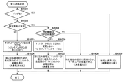
図8は、本実施形態における給電制御処理の手順を示すフローチャートである。図8の各処理は、例えば、CPU301がメモリ303に展開されたプログラムを読み出して実行することにより実現される。
FIG. 8 is a flowchart showing the procedure of power supply control processing in the present embodiment. Each process in FIG. 8 is realized, for example, by the
S801において、CPU301は、電力状態の遷移確認時に、実行中のジョブがあるか否かを判定する。ここで、実行中のジョブがあると判定された場合には、S805において、現在の電力供給状態を維持する。以下、S805の電力供給状態を、「消費電力1:スタンバイ状態」とする。一方、実行中のジョブがないと判定された場合には、S802において、CPU301は、メモリ303やハードディスク106などに記憶されている設定情報(後述)に基づいて、特定機能が有効であるか否かを判定する。
In step S801, the
S802で少なくとも1つの特定機能が有効であると判定された場合、S804において、CPU301は、その特定機能の実行に関係しないデバイスへの電力供給を停止する。以下、S804の電力状態を、「消費電力2:Connected Sleep状態」とする。一方、特定機能が全て無効(非許可)である場合には、S803において、CPU301は、割込処理するための最低限のデバイス以外への電力供給を停止する。以下、S803の電力状態を、「消費電力5:DeepSleep状態」とする。
If it is determined in S802 that at least one specific function is valid, in S804, the
ここで、ジョブについて説明する。本実施形態におけるジョブとは、画像形成装置が実行する処理の一つで、ジョブ実行中は、省電力状態への遷移(S803又はS804)は実行されない。ジョブには、例えば、プリント、スキャン、ユーザデータのバックアップ・リストア、画像形成装置101の情報のサーバ通知、ネットワーク経由のスキャナ装置102やプリンタ装置104やフィニッシャ装置150の設定変更、を行うためのジョブが含まれる。また、ファクシミリに関連するジョブには、例えば、送信予約、プリント待ち、転送中、通話中、通信中、定刻送信、中継中、におけるジョブがある。また、回線切断後一定期間や、ISDNボード接続中、多回線FAXボード接続中、などもジョブとして扱う。ジョブには、上記以外のジョブが含まれても良い。
Here, the job will be described. The job in the present embodiment is one of the processes executed by the image forming apparatus, and the transition to the power saving state (S 803 or S 804) is not executed during job execution. Jobs include, for example, printing, scanning, backup / restoration of user data, server notification of information of the
特定機能について説明する。特定機能とは、ネットワークやファクシミリなどの一部の機能を含み、それらの機能の実行においては、応答時間、受信機能、送信機能、電力不足の点について制約がある機能である。表1に、特定機能と使用するデバイスとの対応を記載した一覧表を表1に示す。 Describe specific functions. The specific function includes some functions such as a network and a facsimile, and in the execution of these functions, there are restrictions on response time, reception function, transmission function, and power shortage. Table 1 shows a list in which correspondences between specific functions and devices to be used are described.

応答時間に制約がある機能とは、例えば、SIP(Session Initiation Protocol)、IPv4/6のマルチキャストDNS(mDNS)、モデムダイヤルイン、ナンバーディスプレイである。それらの機能は、ネットワーク上の他の装置からの要求に対して規定時間(秒単位)以内に応答を返す必要がある。例えば、規定時間は、最短3秒〜6秒であり、スリープ状態からの復帰時間が4秒〜10秒以上かかるとすると、画像形成装置101は、要求を受信しても、規定時間以内に応答を返すことができない。
The functions with restricted response time are, for example, SIP (Session Initiation Protocol), IPv4 / 6 multicast DNS (mDNS), modem dial-in, and number display. Those functions need to respond to requests from other devices on the network within a prescribed time (in seconds). For example, if the prescribed time is 3 seconds to 6 seconds at the shortest, and recovery time from the sleep state takes 4 seconds to 10 seconds or more, the
受信機能に制約がある機能とは、例えば、BMLinkS、IEEE802.1X、AutoIPなどがある。それらの機能は、機能ごとに制約の詳細は異なっており、例えば、BMLinkSでは、応答パターンが複数あり複雑である。また、IEEE802.1Xでは、暗号認証が必要である。また、AutoIPは、空いているIPを許可する機能であるが、1パケット目から2パケット目までの時間によって応答を返すか否かが判定される。それらの機能は、複雑なプロトコル解析や暗号認証等を必要とするものであり、コントローラ部のCPUへの電力供給が行われていないスリープ状態での実行は難しい。 Examples of functions that are restricted in the reception function include BMLinkS, IEEE 802.1X, and AutoIP. The details of the constraints differ depending on the function. For example, in BMLinkS, response patterns are multiple and complex. Also, in IEEE 802.1X, cryptographic authentication is required. In addition, AutoIP is a function to permit free IP, but it is determined whether or not to return a response depending on the time from the first packet to the second packet. Those functions require complicated protocol analysis, cryptographic authentication, and the like, and it is difficult to execute in the sleep state where power supply to the CPU of the controller unit is not performed.
送信機能に制約がある機能とは、例えば、Netware、AppleTalkなどである。それらの機能は、他のクライアント端末からの探索のために、サーバ等への端末登録を定期的に行う必要がある。従って、それらの機能も、コントローラ部のCPUへの電力供給が行われていないスリープ状態での実行は難しい。 Examples of functions that are limited in transmission function include Netware, AppleTalk, and the like. Those functions need to perform terminal registration to a server etc. regularly, in order to search from other client terminals. Therefore, those functions are also difficult to execute in the sleep state where power supply to the CPU of the controller unit is not performed.
電力不足の制約がある機能とは、例えば、ファクシミリの固定受信、ファクシミリの着信呼出、ファクシミリのリモート受信などである。それらの機能は、電話系の機能であり、スリープ状態では電力が足りず、機能が実行できない。例えば、電話系の機能として、着信呼出機能と呼ばれる、ベルの鳴動数を設定して、回線着信時に指定回数分、ベルを鳴動させる機能がある。画像形成装置101がスリープ状態の時に着信を受けると、ハンドセット(電話)は給電されているので、画像形成装置101がスリープ復帰する前に電話が鳴動してしまう。従って、画像形成装置101は、電話の鳴動回数をカウントすることができなくなってしまう。
The functions that are limited in power shortage include, for example, fixed reception of facsimile, incoming call of facsimile, remote reception of facsimile, and the like. Those functions are functions of the telephone system, and in the sleep state, the power is insufficient and the functions can not be performed. For example, as a function of the telephone system, there is a function called an incoming call calling function, which sets the number of ringing bells, and rings the bell for a designated number of times when a line is received. If an incoming call is received while the
本実施形態における特定機能は、上記の機能に限定されず、電力状態によっては、例えばスリープ復帰の時間によって実行が制限される機能であれば、特定機能として扱う。 The specific function in the present embodiment is not limited to the above-described function, and depending on the power state, for example, it is treated as a specific function if it is a function whose execution is limited by the time of sleep recovery.
図9は、LCDパネル200に表示される、SIP機能を有効に設定するための画面である。設定画面900において、ユーザによりボタン901及びOKボタン904が押下されると、画像形成装置101は、SIP機能を有効化する。その際に、CPU301は、画像形成装置101のメモリ303等の記憶領域に、SIP機能が有効である旨の設定情報を格納する。
FIG. 9 is a screen displayed on the
また、ユーザによりボタン902及びOKボタン904が押下されると、SIP機能を無効化する。その際に、CPU301は、画像形成装置101のメモリ303等の記憶領域に、SIP機能が無効である旨の設定情報を格納する。設定画面900上において、ユーザによりボタン901又は902が押下されると、ハイライトが反転する。その際に、ユーザによりキャンセルボタン903が押下されると、ハイライトの反転が取り消される。図9に示す設定画面900は、SIP機能について有効化するためのユーザインタフェース画面として示しているが、上記のような各特定機能について表示されるようにしても良い。
In addition, when the
以下、図8の処理を具体的に説明する。ここでは、mDNSとナンバーディスプレイが有効に設定されている場合について説明する。ファクシミリ送信ジョブが完了した時に、図8の処理が開始する。 The process of FIG. 8 will be specifically described below. Here, the case where mDNS and number display are set to be effective will be described. When the facsimile transmission job is completed, the process of FIG. 8 starts.
まず、画像形成装置101は、電力状態の遷移確認時に実行中のジョブがあるか否かを判定する(S801)。ここで、実行中のジョブがないと判定された場合には、メモリ303やハードディスク106などに記憶されている設定情報に基づいて、少なくとも1つの特定機能が有効であるか否かを判定する(S802)。本例では、mDNSとナンバーディスプレイが有効と設定されているので、各機能とデバイスの対応を表1を参照して取得する。
First, the
表1から、mDNSについては、CPU301、メモリ303、ハードディスク106、NICを含むネットワークコントローラ311への電力供給を維持すると決定する。また、ナンバーディスプレイについては、CPU301、メモリ303、ハードディスク106、FAX−CCUを含むFAX装置107への電力供給を維持すると決定する。
From Table 1, it is determined that the power supply to the
そのため、少なくとも、CPU301、メモリ303、ハードディスク106、NICを含むネットワークコントローラ311、FAX−CCUを含むFAX装置107に対して電力供給を継続し、それ以外のデバイスに対する電力供給を停止する。
Therefore, the power supply is continued to at least the
以上のように、本実施形態では、制約のある特定機能が有効の場合には、その特定機能のジョブが実行されていなくても、特定機能に関係するデバイスへの電力供給を継続しつつ、画像形成装置を省電力状態に遷移させる。その結果、例えば、ネットワーク上の他の装置からの要求によってスリープ復帰する場合でも、スリープ復帰にかかる時間のために要求に対する規定時間以内での応答ができなくなってしまうといったことを回避することができる。 As described above, in the present embodiment, when the specific function with limitations is valid, power supply to devices related to the specific function is continued even if the job of the specific function is not executed. The image forming apparatus is transitioned to the power saving state. As a result, for example, even when returning to sleep due to a request from another device on the network, it is possible to avoid that the response to the request can not be answered within the specified time due to the time taken to return to sleep. .
[第2の実施形態]
本実施形態では、ネットワークを介した受信応答時間に制約がある特定機能が有効である場合には、ネットワークのリンク速度を落とさずに(維持しつつ)、スリープ状態に遷移する。本実施形態では、そのような特定機能としてSIPを例として説明する。SIPでは、画像形成装置は、SIPサーバからの要求に対して、規定時間以内に応答を返さなくてはならない。例えば、SIPサーバの種類によっては、この規定時間は4秒であることがある。
Second Embodiment
In this embodiment, when a specific function that has a restriction on reception response time via the network is effective, the network state transitions to the sleep state without lowering (while maintaining) the link speed. In the present embodiment, SIP will be described as an example of such a specific function. In SIP, the image forming apparatus must respond to a request from the SIP server within a specified time. For example, depending on the type of SIP server, this prescribed time may be 4 seconds.
一般的に、画像形成装置101をスリープ状態に遷移させる場合には、消費電力の低減化のためにリンク速度を低下させることが行われる。しかしながら、スリープ復帰する場合に、リンク速度を復帰させる時間が上記のSIPについての規定時間より長い場合があり得る。そのような場合には、SIPサーバに対する応答ができず、接続がキャンセルされてしまう。そこで、本実施形態では、受信応答時間に制約がある特定機能が有効である場合、リンク速度を維持しつつ、画像形成装置101をスリープ状態に遷移させる。
Generally, when transitioning the
図10は、本実施形態における給電制御処理の手順を示すフローチャートである。図10の各処理は、例えば、CPU301がROMに格納されたプログラムをRAMに読み出して実行することにより実現される。
FIG. 10 is a flowchart showing the procedure of power supply control processing in the present embodiment. Each process in FIG. 10 is realized, for example, by the
S1001において、CPU301は、電力状態の遷移確認時に、実行中のジョブがあるか否かを判定する。ここで、実行中のジョブがあると判定された場合には、S1009において、現在の電力供給状態を維持する。以下、S1009の電力状態を、「消費電力1:スタンバイ状態」とする。一方、実行中のジョブがないと判定された場合には、S1002において、CPU301は、メモリ303やハードディスク106などに記憶されている設定情報に基づいて、特定機能が有効であるか否かを判定する。
In step S1001, the
S1002で特定機能が有効でない(無効である)と判定された場合、S1003において、CPU301は、ネットワークのリンク速度を低下させる。以降、ネットワークのリンク速度を低下させることを、リンクメンテナンスモードをオフにするともいう。その後、S1006において、CPU301は、割込処理のための最低限のデバイス以外への電力供給を停止する。以下、S1006の電力状態を、「消費電力5:DeepSleep状態」とする。
If it is determined in S1002 that the specific function is not valid (is invalid), the
S1002で少なくとも1つの特定機能が有効であると判定された場合、S1004において、CPU301は、有効である特定機能はSIPのみであるか否かを判定する。ここで、有効である特定機能はSIPのみであると判定された場合には、S1005において、CPU301は、ネットワークのリンク速度を維持する。以降、ネットワークのリンク速度を維持することを、リンクメンテナンスモードをオンにするともいう。その後、S1007において、割込処理及びリンク速度維持のための最低限のデバイス以外への電力供給を停止する。以下、S1007の電力状態を、「消費電力4:リンクメンテナンス状態」とする。
If it is determined in S1002 that at least one specific function is valid, the
S1004で有効である特定機能はSIPのみでないと判定された場合には、S1008において、CPU301は、表1を参照し、特定機能の実行に関係しないデバイスへの電力供給を停止する。例えば、CPU301は、SIPの場合には、表1を参照し、SIPがCPU301、メモリ303、ハードディスク106、NICを含むネットワークコントローラ311への電力供給を維持することを決定する。そして、少なくとも、CPU301、メモリ303、ハードディスク106、NICを含むネットワークコントローラ311への電力供給を継続し、それ以外へのデバイスへの電力供給を停止するように制御する。以下、S1008の電力状態を、「消費電力2:ConnectedSleep状態」とする。
If it is determined in S1004 that the specific function that is valid is not SIP, in S1008, the
図1において、「消費電力1:スタンバイ状態」の消費電力は、例えば、26〜50Wであり、「消費電力2:ConnectedSleep状態」の消費電力は、例えば、12〜18Wである。また、「消費電力4:リンクメンテナンス状態」の消費電力は、例えば、1.6Wであり、「消費電力5:DeepSleep状態」の消費電力は、例えば、1W以下である。 In FIG. 1, the power consumption of “power consumption 1: standby state” is, for example, 26 to 50 W, and the power consumption of “power consumption 2: connected sleep state” is, for example, 12 to 18 W. Further, the power consumption of the “power consumption 4: link maintenance state” is, for example, 1.6 W, and the power consumption of the “power consumption 5: deep sleep state” is, for example, 1 W or less.
以上のように、本実施形態では、ネットワークを介した受信応答時間に制約がある特定機能が有効である場合に、リンク速度を維持しつつ、画像形成装置をスリープ状態に遷移させる。また、その特定機能が無効である場合には、リンク速度を低下させて、画像形成装置をスリープ状態に遷移させる。 As described above, in the present embodiment, the image forming apparatus is transitioned to the sleep state while maintaining the link speed when the specific function having a restriction on the reception response time via the network is effective. If the specific function is invalid, the link speed is reduced to shift the image forming apparatus to the sleep state.
[第3の実施形態]
本実施形態では、特定機能の例としてSIPを説明する。SIPは、サーバがIP端末のサーバへの定期的な再登録時間間隔を指定するプロトコルとして用いられる。サーバがIP端末の再登録時間間隔を指定するプロトコルは、SIP以外にも、DHCPなどがある。しかしながら、DHCPの場合、そのような時間間隔は、8時間や24時間といった比較的長期間である場合が多い。一方、例えば、NGN(Next Generation Network)環境下のIP−FAXに用いられているSIPでは、SIPサーバはIP端末の再登録時間間隔を1時間として規定している。また、パケットロスによる再送のために半分以下の時間を設定するのであれば、30分以下での再登録が必要とされる。また、HUB上のSIPサーバは、製品によっては、IP端末の再登録時間間隔が秒単位として設定されていることがある。以上から、SIPサーバのIP端末の再登録時間間隔は、数秒〜数十分であると考えられる。
Third Embodiment
In the present embodiment, SIP will be described as an example of a specific function. SIP is used as a protocol for a server to specify a periodic re-registration time interval with an IP terminal server. A protocol for specifying the reregistration time interval of the IP terminal by the server is not only SIP but also DHCP. However, for DHCP, such time intervals are often relatively long, such as 8 hours or 24 hours. On the other hand, for example, in SIP used for IP-FAX under an NGN (Next Generation Network) environment, the SIP server defines the IP terminal re-registration time interval as one hour. If half or less time is set for retransmission due to packet loss, re-registration within 30 minutes is required. Also, depending on the product, the SIP server on the HUB may set the re-registration time interval of the IP terminal as a unit of seconds. From the above, it is considered that the re-registration time interval of the IP terminal of the SIP server is several seconds to several tens of minutes.
サーバへのIP端末の再登録時間間隔は、DHCPでは、8時間や24時間というように、比較的長期間である。その場合には、ジョブがないことやユーザ操作が一定期間ないことを条件として、第2の実施形態で説明したように、画像形成装置101は、リンクメンテナンスモードをオンにしてスリープ状態に遷移することができる。
The re-registration time interval of the IP terminal to the server is relatively long, such as 8 hours or 24 hours in DHCP. In that case, as described in the second embodiment, the
一般的に、画像形成装置は、SIPサーバで規定されているIP端末の再登録時間間隔の40%の時間間隔で、SIPサーバへの再登録を行うことが多い。これは、1パケット目の到着が遅延したり、パケットロスとなったとしても、2パケット目でリカバリ可能とするためである。例えば、SIPサーバでの設定時間間隔が1時間であれば、画像形成装置101からの送信間隔は、1時間の40%の24分となる。また、SIPサーバでの設定時間間隔が10分であれば、画像形成装置101からの送信間隔は、10分の40%の4分となる。このような短時間間隔でSIPサーバへの再登録が行われると、例えば、ユーザ操作等がない場合、SIPサーバへの再登録のみが行われているに過ぎない状態であっても、画像形成装置101はスリープ状態に遷移することができない。
Generally, the image forming apparatus often performs re-registration with the SIP server at a time interval of 40% of the re-registration time interval of the IP terminal defined by the SIP server. This is to make it possible to recover the second packet even if the arrival of the first packet is delayed or packet loss occurs. For example, if the setting time interval in the SIP server is one hour, the transmission interval from the
本実施形態では、ネットワークを介した受信応答時間に制約がある特定機能が有効である場合に、さらに、サーバへの送信間隔(例えば、SIPサーバへのIP端末の再登録時間間隔)を考慮して、遷移先の省電力状態を変更する。 In the present embodiment, when a specific function that has a restriction on reception response time via the network is effective, the transmission interval to the server (for example, the re-registration time interval of the IP terminal to the SIP server) is further considered. Change the power saving state of the transition destination.
図11は、本実施形態における給電制御処理の手順を示すフローチャートである。図11の各処理は、例えば、CPU301がROMに格納されたプログラムをRAMに読み出して実行することにより実現される。図11は、S1106の処理の点で、図10と異なる。図11のS1101〜S1105、S1107〜S1110は、各S1001〜S1005、S1006〜S1009に対応する。
FIG. 11 is a flowchart showing the procedure of power supply control processing in the present embodiment. Each process in FIG. 11 is realized, for example, by the
S1105でリンクメンテナンスモードがオンとされると、S1106において、CPU301は、SIPサーバへのIP端末の再登録時間間隔の設定値が所定の閾値以上であるか否かを判定する。ここで、所定の閾値以上であると判定された場合には、S1108に進む。一方、所定の閾値以上でない(閾値未満)であると判定された場合には、S1109に進む。
When the link maintenance mode is turned on in S1105, the
即ち、SIPサーバへのIP端末の再登録時間間隔が2分など、所定の閾値未満で短い場合には、画像形成装置101を、特定機能の実行に関係しないデバイスへの電力供給を停止する「消費電力2:Connected Sleep状態」に遷移させる。つまり、第2の実施形態では、特定機能がSIPのみの場合には、割込処理及びリンク速度維持のための最低限のデバイスに対してのみ電力供給すれば良かった。しかしながら、再登録時間間隔が所定の閾値未満である場合には、CPU301、メモリ303、ハードディスク106、NICを含むネットワークコントローラ311への電力供給を継続する。従って、第2の実施形態ではスリープ状態において給電停止が可能な部分(CPU301、メモリ303、ハードディスク106)まで電力供給している。しかしながら、スリープ状態に遷移できずに「消費電力1:スタンバイ状態」が継続される場合より、消費電力を低減しつつ、SIPサーバへのIP端末の再登録動作を行うことが可能となる。
That is, when the re-registration time interval of the IP terminal to the SIP server is shorter than a predetermined threshold, such as 2 minutes, the
図12及び図13を参照しながら、本実施形態の効果について説明する。図12、及び本実施形態に係る図13において、縦軸は電力消費量を表し、横軸は時間軸を表している。また、図12(a)及び図13(a)は、SIPサーバへのIP端末の再登録時間間隔が21分以上の場合を示している。また、図12(b)及び図13(b)は、SIPサーバへのIP端末の再登録時間間隔が11分以上21分未満の場合を示している。また、図12(c)及び図13(c)は、SIPサーバへのIP端末の再登録時間間隔が11分未満の場合を示している。図12及び図13では、S1106で用いられる所定の閾値が20分の場合を示している。 The effects of the present embodiment will be described with reference to FIGS. 12 and 13. In FIG. 12 and FIG. 13 according to the present embodiment, the vertical axis represents power consumption, and the horizontal axis represents a time axis. 12A and 13A show the case where the re-registration time interval of the IP terminal to the SIP server is 21 minutes or more. 12B and 13B show the case where the re-registration time interval of the IP terminal to the SIP server is 11 minutes or more and less than 21 minutes. 12 (c) and 13 (c) show a case where the re-registration time interval of the IP terminal to the SIP server is less than 11 minutes. 12 and 13 show the case where the predetermined threshold used in S1106 is 20 minutes.
・再登録設定時間間隔が21分以上の場合
図12(a)及び図13(a)は、SIPサーバへのIP端末の再登録時間間隔が21分以上の場合の電力状態の遷移を示す図である。図12(a)のS1201において、画像形成装置101の電力状態は、割込みの一要因であるRTC312により、スリープ状態である「消費電力4:リンクメンテナンス状態」から、「消費電力1:スタンバイ状態」へスリープ復帰する。
When Re-Registration Setting Time Interval is More Than 21 Minutes FIG. 12A and FIG. 13A show the transition of the power state when the re-registration time interval of the IP terminal to the SIP server is more than 21 minutes. It is. In
画像形成装置101は、スリープ復帰後、直ちに、次のIP端末の再登録時間間隔を設定するイベントを発行し、RTC312に再設定する(S1202)。再登録時間間隔は、25分とする。「消費電力4:リンクメンテナンス状態」から、「消費電力1:スタンバイ状態」へスリープ復帰すると、ハードディスク106やリレースイッチ等のデバイス保護タイマが起動する(S1203)。ここで、デバイス保護タイマは、10分間とする。
Immediately after returning from the sleep state, the
デバイス保護タイマがタイムアップすると、近い時刻にアラームがあるか否かの判定が行われる(S1204)。アラームとは、例えば、次回のIP端末再登録時刻である。このようなアラーム判定が行われる理由としては、消費電力を低減させても割込みによりすぐに復帰する場合には、消費電力を効率良く低減することができないからである。ここで、アラーム判定は、10分間とする。 When the device protection timer times out, it is determined whether there is an alarm at a near time (S1204). The alarm is, for example, the next IP terminal re-registration time. The reason why such an alarm determination is performed is that even if power consumption is reduced, power consumption can not be efficiently reduced if it returns immediately due to an interrupt. Here, alarm determination is performed for 10 minutes.
本例の場合、IP端末の再登録時間間隔は25分であるので、図12(a)に示すように、アラーム判定では、アラームなしと判定される。アラームなしと判定された場合には、電力状態は、「消費電力1:スタンバイ状態」から「消費電力4:リンクメンテナンス状態」へ遷移する。その15分後(25分−デバイス保護タイマ10分)に、電力状態は、再び、「消費電力1:スタンバイ状態」へスリープ復帰する(S1205)。その後、上記の処理を繰り返す。図13(a)は、図12(a)と同じである。 In the case of this example, since the re-registration time interval of the IP terminal is 25 minutes, as shown in FIG. 12A, in the alarm determination, it is determined that there is no alarm. When it is determined that there is no alarm, the power state transitions from “power consumption 1: standby state” to “power consumption 4: link maintenance state”. After 15 minutes (25 minutes-device protection timer 10 minutes), the power state returns to sleep again to "power consumption 1: standby state" (S1205). Thereafter, the above process is repeated. FIG. 13 (a) is the same as FIG. 12 (a).
・再登録設定時間間隔が11分以上21分未満の場合
図12(b)及び図13(b)は、SIPサーバへのIP端末の再登録時間間隔が11分以上21分未満の場合の電力状態の遷移を示す図である。
-When the re-registration setting time interval is 11 minutes or more and less than 21 minutes: In FIG. 12B and FIG. 13B, the power when the re-registration time interval of the IP terminal to the SIP server is 11 minutes or more and less than 21 minutes It is a figure showing transition of a state.
図12(b)のS1211において、画像形成装置101の電力状態は、割込みの一要因であるRTC312により、スリープ状態である「消費電力4:リンクメンテナンス状態」から、「消費電力1:スタンバイ状態」へスリープ復帰する。
In S1211 of FIG. 12B, the power state of the
画像形成装置101は、スリープ復帰後、直ちに、次のIP端末の再登録時間間隔を設定するイベントを発行し、RTC312に再設定する(S1212)。再登録時間間隔は、15分とする。「消費電力4:リンクメンテナンス状態」から、「消費電力1:スタンバイ状態」へスリープ復帰すると、ハードディスク106やリレースイッチ等のデバイス保護タイマが起動する(S1213)。ここで、デバイス保護タイマは、10分間とする。
Immediately after returning from the sleep state, the
デバイス保護タイマがタイムアップすると、近い時刻にアラームがあるか否かの判定が行われる(S1214)。ここで、アラーム判定は、10分間とする。 When the device protection timer times out, it is determined whether there is an alarm at a near time (S1214). Here, alarm determination is performed for 10 minutes.
本例の場合、IP端末の再登録時間間隔は15分であるので、図12(b)に示すように、15分−デバイス保護タイマ10分=5分がアラーム判定の10分間に含まれることになるので、アラーム判定では、アラームありと判定される。そして、再登録時間間隔の15分が経過すると、直ちに、次のIP端末の再登録時間間隔を設定するイベントを発行し、RTC312に再設定する(S1215)。再登録時間間隔は、15分である。 In the case of this example, since the re-registration time interval of the IP terminal is 15 minutes, as shown in FIG. 12B, 10 minutes of device protection timer 10 minutes = 5 minutes is included in 10 minutes of the alarm determination. Therefore, in the alarm determination, it is determined that there is an alarm. Then, when 15 minutes of the reregistration time interval elapses, an event for setting the reregistration time interval of the next IP terminal is issued immediately, and is reset in the RTC 312 (S1215). The re-registration time interval is 15 minutes.
RTC312への再設定の後、直ちに、再度、アラーム判定が行われる(S1216)。その場合のアラーム判定では、図12(b)に示すように、RTCへの再設定から15分後は、アラーム判定の10分間に含まれないことになるので、アラーム判定ではアラームなしと判定される。アラームなしと判定された場合には、電力状態は、「消費電力1:スタンバイ状態」から「消費電力4:リンクメンテナンス状態」へ遷移する。
Immediately after resetting to the
RTC312への再設定の後から15分後に、画像形成装置101の電力状態は、RTC312により、スリープ状態である「消費電力4:リンクメンテナンス状態」から、「消費電力1:スタンバイ状態」へスリープ復帰する(S1217)。その後、上記の処理を繰り返す。
The power state of the
図12(b)では、デバイス保護タイマ10分間において、電力状態は「消費電力1:スタンバイ状態」となっているが、デバイス保護タイマを起動させる必要がない場合には、その間を「消費電力4:リンクメンテナンス状態」とするようにしても良い。 In FIG. 12B, the power state is “power consumption 1: standby state” in 10 minutes of the device protection timer, but when it is not necessary to start the device protection timer, “power consumption 4” is displayed. : Link maintenance status may be set.
図13(b)は、図11の処理を実行した結果を示す図である。本例では、再登録時間間隔は15分であるので、図11のS1106において所定の閾値20分未満であると判定される。 FIG.13 (b) is a figure which shows the result of having performed the process of FIG. In this example, since the re-registration time interval is 15 minutes, it is determined in S1106 of FIG. 11 that the predetermined threshold is less than 20 minutes.
図13(b)のタイミングチャートには図示されていないが、S1211の前段で、図11の処理が行われて、S1109で画像形成装置101の電力状態は「消費電力2:ConnectedSleep状態」に遷移している。この後、ユーザ操作等がなく、SIPサーバへのIP端末の再登録動作が続く限りは、画像形成装置101の電力状態は、「消費電力2:ConnectedSleep状態」を維持する。図13(b)のS1212〜S1217は、図12(b)のS1212〜S1217と同じである。
Although not illustrated in the timing chart of FIG. 13B, the process of FIG. 11 is performed at a stage prior to S1211, and the power state of the
図13(b)に示すように、電力状態変化1301よりも、本実施形態による電力状態変化1302の方が、消費電力は全体として低減される。また、図12(b)では、消費電力が「消費電力1:スタンバイ状態」と「消費電力4:リンクメンテナンス状態」の間で一定していなかったが、図13(b)では、消費電力をConnectedSleep状態で一定に保つことができる。
As shown in FIG. 13B, the power consumption is reduced as a whole in the power state change 1302 according to the present embodiment rather than the
・再登録設定時間間隔が11分未満の場合
図12(c)及び図13(c)は、SIPサーバへのIP端末の再登録時間間隔が11分未満の場合の電力状態の遷移を示す図である。
-When the re-registration setting time interval is less than 11 minutes. FIG. 12C and FIG. 13C show the transition of the power state when the re-registration time interval of the IP terminal to the SIP server is less than 11 minutes. It is.
図12(c)のS1221において、画像形成装置101の電力状態は、割込みの一要因であるRTC312により、スリープ状態である「消費電力4:リンクメンテナンス状態」から、「消費電力1:スタンバイ状態」へスリープ復帰する。
In S1221 of FIG. 12C, the power state of the
画像形成装置101は、スリープ復帰後、直ちに、次のIP端末の再登録時間間隔を設定するイベントを発行し、RTC312に再設定する(S1222)。再登録時間間隔は、5分とする。「消費電力4:リンクメンテナンス状態」から、「消費電力1:スタンバイ状態」へスリープ復帰すると、ハードディスク106やリレースイッチ等のデバイス保護タイマが起動する(S1223)。ここで、デバイス保護タイマは、10分間とする。
Immediately after returning from the sleep state, the
RTC312への再設定の後、直ちに、アラーム判定が行われる(S1224)。その場合のアラーム判定では、図12(c)に示すように、アラーム判定の10分間はまだ計測開始されていないので、アラームなしと判定される。しかしながら、デバイス保護タイマは起動しているので、「消費電力1:スタンバイ状態」を維持する。そして、再登録時間間隔の5分が経過すると、直ちに、次のIP端末の再登録時間間隔5分を設定するイベントを発行し、RTC312に再設定する(S1225)。
Immediately after resetting to the
RTC312への再設定の後、直ちに、再度、アラーム判定が行われる(S1226)。本例の場合、再登録時間間隔5分がアラーム判定の10分間に含まれるので、アラーム判定では必ずアラームありと判定される。従って、画像形成装置101の電力状態は、「消費電力1:スタンバイ状態」からスリープ状態に遷移しない。
Immediately after resetting to the
図13(c)は、図11の処理を実行した結果を示す図である。本例では、再登録時間間隔は5分であるので、図11のS1106において所定の閾値20分未満であると判定される。 FIG.13 (c) is a figure which shows the result of having performed the process of FIG. In this example, since the re-registration time interval is 5 minutes, it is determined that the predetermined threshold is less than 20 minutes in S1106 of FIG.
図13(c)のタイミングチャートには図示されていないが、S1221の前段で、図11の処理が行われて、S1109で画像形成装置101の電力状態は「消費電力2:ConnectedSleep状態」に遷移している。この後、ユーザ操作等がなく、SIPサーバへのIP端末の再登録動作が続く限りは、画像形成装置101の電力状態は、「消費電力2:ConnectedSleep状態」を維持する。図13(c)のS1222〜S1226は、図12(b)のS1222〜S1226と同じである。
Although not illustrated in the timing chart of FIG. 13C, the process of FIG. 11 is performed at a stage prior to S1221, and the power state of the
図13(c)に示すように、電力状態変化1303から、本実施形態による電力状態変化1304まで消費電力を低減することができる。
As shown in FIG. 13C, power consumption can be reduced from the
図12に示すように、ネットワークを介した受信応答時間に制約がある特定機能が有効であり、且つ、短時間間隔でサーバへの送信を行う必要がある場合には、画像形成装置は、省電力モードに遷移できず、消費電力が多い状態を継続しなければならなかった。本実施形態では、図13に示すように、送信時間間隔に応じて、電力状態の遷移先を変更する。その結果、画像形成装置101の電力状態を効率的に低減することができる。
As shown in FIG. 12, when a specific function that restricts reception response time via the network is effective and transmission to the server is required at short time intervals, the image forming apparatus saves time. It was not possible to transition to the power mode, and it was necessary to continue the state of high power consumption. In the present embodiment, as shown in FIG. 13, the transition destination of the power state is changed according to the transmission time interval. As a result, the power state of the
[第4の実施形態]
本実施形態の画像形成装置101では、ネットワークを介した受信応答時間に制約があり且つ短時間間隔でサーバに送信を行う特定機能が有効であり、且つ、スピンアップ時間が長いハードディスク106が装着されている。本実施形態では、上述の第3の実施形態の動作に加えて、ハードディスク106のスピンアップ時間の長短に応じて、画像形成装置101の電力状態の遷移先を変更する。サーバがIP端末の再登録時間間隔を指定するプロトコルは、SIP以外にも、DHCPなどがあるが、本実施形態においても、再登録時間間隔が比較的短いSIPを例として説明する。
Fourth Embodiment
In the
図14は、本実施形態における給電制御処理の手順を示すフローチャートである。図14の各処理は、例えば、CPU301がROMに格納されたプログラムをRAMに読み出して実行することにより実現される。図14は、S1406〜S1409、S1412の点で、図11と異なる。図14のS1401〜S1406、S1410、S1411、S1413、S1414は、各S1101〜S1106、S1107、S1108、S1109、S1110に対応する。
FIG. 14 is a flowchart showing the procedure of power supply control processing in the present embodiment. Each process in FIG. 14 is realized, for example, by the
S1406でSIPサーバへのIP端末の再登録時間間隔の設定値が所定の閾値以上であると判定された場合、S1407において、CPU301は、ハードディスク106のスピンアップ時間は閾値以上であるか否かを判定する。ここで、スピンアップ時間が閾値以上でないと判定された場合にはS1408に進み、一方、閾値以上である場合にはS1409に進む。S1407の判定は、例えば、記憶領域に予め保存されたスピンアップ時間とハードディスクモデルとの対応を示すテーブルに基づいて行うようにしても良い。または、画像形成装置101の電源投入時に、ハードディスク106の駆動開始からR/W可能となる状態までの時間を実測し、その測定値に基づいて判定が行われても良い。
If it is determined in S1406 that the setting value of the reregistration time interval of the IP terminal to the SIP server is greater than or equal to the predetermined threshold, the
S1408において、CPU301は、スリープ状態に遷移する際にハードディスク106の駆動をオフにするよう設定する。ここで、スリープ状態に遷移する際にハードディスク106の駆動をオフにすることがデフォルトで設定されている場合には、S1408において特に処理は行われず、S1411に進む。S1411においては、CPU301は、割込処理及びリンク速度維持のための最低限のデバイス以外への電力供給を停止する(「消費電力4:リンクメンテナンス状態」)。
In step S1408, the
S1409において、CPU301は、スリープ状態に遷移する際にハードディスク106の駆動をオンにするよう(回転速度を維持するよう)設定する。S1412においては、CPU301は、割込処理、リンク速度維持、及びハードディスク回転維持のための最低限のデバイス以外への電力供給を停止する(「消費電力3:HDD回転保持状態」)。
In step S1409, the
以上のように、本実施形態によると、ハードディスク106のスピンアップ時間が長い場合には、ハードディスク106の回転を維持しつつ、スリープ状態に遷移する。その結果、スリープ復帰時に、スピンアップ時間のためにサーバへのIP端末の再登録動作ができなくなってしまうことを防ぐことができる。
As described above, according to the present embodiment, when the spin-up time of the
図14では、S1407の判定処理は、S1406の判定処理の後段で行われているが、他の箇所で行われても良い。例えば、S1402で特定機能が有効とされていないと判定された場合に行うようにしても良い。その場合に、スピンアップ時間が閾値より長いと判定されると、割込み処理及びハードディスク回転維持のための最低限のデバイス以外への電力供給が停止され、結果、S1410とS1411の間の消費電力状態となる。つまり、スピンアップ時間が閾値未満と判定された場合の消費電力よりも、ハードディスクの駆動を維持するための消費電力分増えた消費電力状態に遷移することになる。 In FIG. 14, the determination process of S1407 is performed at a later stage of the determination process of S1406, but may be performed at another location. For example, it may be performed when it is determined in S1402 that the specific function is not validated. In this case, if it is determined that the spin-up time is longer than the threshold, power supply to devices other than the minimum device for interrupt processing and hard disk rotation maintenance is stopped, and as a result, the power consumption state between S1410 and S1411. It becomes. That is, transition to the power consumption state in which the power consumption for maintaining the drive of the hard disk is increased is higher than the power consumption when the spin-up time is determined to be less than the threshold.
本発明は、以下の処理を実行することによっても実現される。即ち、上述した実施形態の機能を実現するソフトウェア(プログラム)を、ネットワーク又は各種記憶媒体を介してシステム或いは装置に供給し、そのシステム或いは装置のコンピュータ(またはCPUやMPU等)がプログラムを読み出して実行する処理である。 The present invention is also realized by performing the following processing. That is, software (program) for realizing the functions of the above-described embodiments is supplied to a system or apparatus via a network or various storage media, and a computer (or CPU, MPU or the like) of the system or apparatus reads the program. It is a process to execute.
101 画像形成装置: 103 コントローラ: 301、321 CPU: 303、323 メモリ 101 image forming apparatus: 103 controller: 301, 321 CPU: 303, 323 memory
Claims (23)
ネットワークを介しての送信もしくは受信に関する特定の機能の設定を記憶する記憶手段と、
前記ネットワークを介して外部装置から要求を受信し、前記ネットワークを介して前記外部装置へ前記要求に対する応答を送信する通信制御手段と、
前記通信制御手段により受信した前記要求について処理を実行する処理手段と、
前記画像形成装置を、所定の電力状態から、電力消費量が前記所定の電力状態における電力消費量よりも低く且つ電力が前記処理手段及び前記通信制御手段に供給される第1の省電力状態に移行させ、前記画像形成装置を、前記所定の電力状態から、電力消費量が前記所定の電力状態における電力消費量よりも低く且つ電力が前記処理手段に供給されず前記通信制御手段に供給される第2の省電力状態に移行させる電力制御手段と、を備え、
前記電力制御手段は、前記記憶手段に記憶された前記特定の機能の設定に基づいて、移行すべき省電力状態として前記第1の省電力状態もしくは前記第2の省電力状態を決定し、所定の条件が満たされた場合に、当該決定された省電力状態へ前記画像形成装置を前記所定の電力状態から移行させ、
前記通信制御手段は、前記通信制御手段の通信速度を変更可能であり、
前記電力制御手段が前記画像形成装置を前記第1の省電力状態へ移行させる場合、前記通信制御手段は、前記通信制御手段の通信速度を変更せず、前記電力制御手段が前記画像形成装置を前記第2の省電力状態へ移行させる場合、前記通信制御手段は、前記通信制御手段の通信速度を変更する、
ことを特徴とする画像形成装置。 An image forming apparatus capable of taking a plurality of power saving states,
Storage means for storing settings of specific functions related to transmission or reception via the network;
Communication control means for receiving a request from an external device via the network and transmitting a response to the request to the external device via the network;
Processing means for performing processing on the request received by the communication control means;
In the image forming apparatus, from a predetermined power state, to a first power saving state in which the power consumption is lower than the power consumption in the predetermined power state and power is supplied to the processing means and the communication control means The image forming apparatus is shifted from the predetermined power state to a power consumption amount lower than the power consumption amount in the predetermined power state and power is supplied to the communication control means without being supplied to the processing means. Power control means for shifting to a second power saving state ;
The power control means determines the first power saving state or the second power saving state as the power saving state to be shifted based on the setting of the specific function stored in the storage means If the condition is satisfied, the image forming apparatus is shifted from the predetermined power state to the power-saving state in which the determined,
The communication control means is capable of changing the communication speed of the communication control means,
When the power control unit causes the image forming apparatus to shift to the first power saving state, the communication control unit does not change the communication speed of the communication control unit, and the power control unit does not change the image forming apparatus. When transitioning to the second power saving state, the communication control unit changes the communication speed of the communication control unit.
An image forming apparatus characterized by
前記特定の機能としての、ファクシミリに関連する機能が有効である場合、前記ファクシミリ手段は、着信呼の受信に従ってベルを鳴動させることを特徴とする請求項1乃至8のいずれか1項に記載の画像形成装置。 And facsimile means for receiving facsimile data.
As the specific function, if functionality related to a facsimile is valid, the facsimile unit, according to any one of claims 1 to 8, characterized in that to sound the bell according to the received incoming call Image forming apparatus.
前記第1の省電力状態および前記第2の省電力状態において、電力は前記画像処理手段へ供給されない、
ことを特徴とする請求項1乃至10のいずれか1項に記載の画像形成装置。 And image processing means for executing image processing,
Power is not supplied to the image processing means in the first power saving state and the second power saving state.
The image forming apparatus according to any one of claims 1 to 10 , wherein
ネットワークを介しての送信もしくは受信に関する特定の機能の設定を記憶する記憶手段と、
前記ネットワークを介して外部装置から要求を受信し、前記ネットワークを介して前記外部装置へ前記要求に対する応答を送信する通信制御手段と、
前記通信制御手段により受信した前記要求について処理を実行する処理手段と、
所定の条件が満たされた場合に前記特定の機能の設定に基づいて、前記画像形成装置を、所定の電力状態から、電力消費量が前記所定の電力状態における電力消費量よりも低く且つ電力が前記処理手段及び前記通信制御手段に供給される第1の省電力状態に移行させるか、もしくは、前記画像形成装置を、前記所定の電力状態から、電力消費量が前記所定の電力状態における電力消費量よりも低く且つ電力が前記処理手段に供給されず前記通信制御手段に供給される第2の省電力状態に移行させる電力制御手段と、を備え、
前記通信制御手段は、前記通信制御手段の通信速度を変更可能であり、
前記電力制御手段が前記画像形成装置を前記第1の省電力状態へ移行させる場合、前記通信制御手段は、前記通信制御手段の通信速度を変更せず、前記電力制御手段が前記画像形成装置を前記第2の省電力状態へ移行させる場合、前記通信制御手段は、前記通信制御手段の通信速度を変更する、
を備えることを特徴とする画像形成装置。 An image forming apparatus capable of taking a plurality of power saving states,
Storage means for storing settings of specific functions related to transmission or reception via the network;
Communication control means for receiving a request from an external device via the network and transmitting a response to the request to the external device via the network;
Processing means for performing processing on the request received by the communication control means;
Based on the setting of the specific function when a predetermined condition is satisfied, the image forming apparatus is determined from the predetermined power state, the power consumption is lower than the power consumption in the predetermined power state, and the power is lower Power is transferred to the first power saving state supplied to the processing means and the communication control means, or from the predetermined power state, the power consumption in the predetermined power state is changed from the predetermined power state. Power control means for transitioning to a second power saving state wherein the amount is lower than the amount and power is not supplied to the processing means and is supplied to the communication control means ;
The communication control means is capable of changing the communication speed of the communication control means,
When the power control unit causes the image forming apparatus to shift to the first power saving state, the communication control unit does not change the communication speed of the communication control unit, and the power control unit does not change the image forming apparatus. When transitioning to the second power saving state, the communication control unit changes the communication speed of the communication control unit.
An image forming apparatus comprising:
前記特定の機能としての、ファクシミリに関連する機能が有効である場合、前記ファクシミリ手段は、着信呼の受信に従ってベルを鳴動させることを特徴とする請求項13乃至19のいずれか1項に記載の画像形成装置。 And facsimile means for receiving facsimile data.
20. A facsimile as claimed in any one of claims 13 to 19 , characterized in that the facsimile means ring the bell according to the reception of the incoming call if the function associated with the facsimile as said particular function is active. Image forming apparatus.
前記第1の省電力状態および前記第2の省電力状態において、電力は前記画像処理手段へ供給されない、
ことを特徴とする請求項13乃至21のいずれか1項に記載の画像形成装置。 And image processing means for executing image processing,
Power is not supplied to the image processing means in the first power saving state and the second power saving state.
An image forming apparatus according to any one of claims 13 to 21 , characterized in that:
Priority Applications (7)
| Application Number | Priority Date | Filing Date | Title |
|---|---|---|---|
| JP2014208340A JP6425490B2 (en) | 2014-10-09 | 2014-10-09 | Image forming apparatus, control method and program |
| CN201510621680.3A CN105516529B (en) | 2014-10-09 | 2015-09-25 | Image forming apparatus and control method |
| CN201910419175.9A CN110058670B (en) | 2014-10-09 | 2015-09-25 | Image forming apparatus and control method |
| US14/868,824 US9503600B2 (en) | 2014-10-09 | 2015-09-29 | Image forming apparatus that shifts into different power saving states and control method thereof |
| EP15002804.1A EP3013026B1 (en) | 2014-10-09 | 2015-09-30 | Image forming apparatus and control method |
| KR1020150141380A KR102006520B1 (en) | 2014-10-09 | 2015-10-08 | Image forming apparatus and control method |
| US15/298,504 US10110764B2 (en) | 2014-10-09 | 2016-10-20 | Image forming apparatus that shifts into different power saving states and control method thereof |
Applications Claiming Priority (1)
| Application Number | Priority Date | Filing Date | Title |
|---|---|---|---|
| JP2014208340A JP6425490B2 (en) | 2014-10-09 | 2014-10-09 | Image forming apparatus, control method and program |
Publications (3)
| Publication Number | Publication Date |
|---|---|
| JP2016082252A JP2016082252A (en) | 2016-05-16 |
| JP2016082252A5 JP2016082252A5 (en) | 2017-11-24 |
| JP6425490B2 true JP6425490B2 (en) | 2018-11-21 |
Family
ID=54293011
Family Applications (1)
| Application Number | Title | Priority Date | Filing Date |
|---|---|---|---|
| JP2014208340A Active JP6425490B2 (en) | 2014-10-09 | 2014-10-09 | Image forming apparatus, control method and program |
Country Status (5)
| Country | Link |
|---|---|
| US (2) | US9503600B2 (en) |
| EP (1) | EP3013026B1 (en) |
| JP (1) | JP6425490B2 (en) |
| KR (1) | KR102006520B1 (en) |
| CN (2) | CN110058670B (en) |
Families Citing this family (14)
| Publication number | Priority date | Publication date | Assignee | Title |
|---|---|---|---|---|
| JP6415210B2 (en) * | 2014-06-19 | 2018-10-31 | キヤノン株式会社 | Information processing apparatus and failure detection method for information processing apparatus |
| JP6425490B2 (en) * | 2014-10-09 | 2018-11-21 | キヤノン株式会社 | Image forming apparatus, control method and program |
| JP6525719B2 (en) | 2015-05-11 | 2019-06-05 | キヤノン株式会社 | IMAGE FORMING APPARATUS, CONTROL METHOD THEREOF, AND PROGRAM |
| JP7027027B2 (en) * | 2016-03-17 | 2022-03-01 | キヤノン株式会社 | Information processing equipment, control methods, and their programs |
| JP6381598B2 (en) * | 2016-09-23 | 2018-08-29 | キヤノン株式会社 | Image communication apparatus and control method and program thereof |
| JP2019034490A (en) * | 2017-08-18 | 2019-03-07 | 富士ゼロックス株式会社 | Information processing device |
| US10469250B2 (en) * | 2017-12-22 | 2019-11-05 | Max Adel Rady | Physical item mapping to blockchain framework |
| JP2020107233A (en) * | 2018-12-28 | 2020-07-09 | キヤノン株式会社 | Storage control device, control method therefor and program |
| JP7401234B2 (en) * | 2019-09-25 | 2023-12-19 | 東芝テック株式会社 | Image forming apparatus and control method |
| KR20210043873A (en) * | 2019-10-14 | 2021-04-22 | 휴렛-팩커드 디벨롭먼트 컴퍼니, 엘.피. | Error detection using dual checks of analog signals |
| WO2021187197A1 (en) * | 2020-03-18 | 2021-09-23 | ソニーグループ株式会社 | Information processing device and information processing method |
| TWI743775B (en) * | 2020-05-07 | 2021-10-21 | 技嘉科技股份有限公司 | Power switch device |
| JP2022072012A (en) * | 2020-10-29 | 2022-05-17 | 京セラドキュメントソリューションズ株式会社 | Image forming device |
| JP2023142622A (en) * | 2022-03-25 | 2023-10-05 | 富士フイルムビジネスイノベーション株式会社 | Information processing apparatus and program |
Family Cites Families (38)
| Publication number | Priority date | Publication date | Assignee | Title |
|---|---|---|---|---|
| JPH09214623A (en) * | 1996-01-30 | 1997-08-15 | Canon Inc | Data communication equipment |
| JPH09261381A (en) * | 1996-03-26 | 1997-10-03 | Canon Inc | Facsimile equipment and method for controlling its stand-by mode |
| JP3524352B2 (en) * | 1997-11-14 | 2004-05-10 | キヤノン株式会社 | Power saving control device |
| KR100338734B1 (en) * | 1998-07-31 | 2002-07-18 | 윤종용 | Printer and method of controlling power consumption of the same |
| JP2003089254A (en) | 2001-09-18 | 2003-03-25 | Canon Inc | Information input-output device, image processor, method for controlling network of image processor, network controlling program, and computer-readable recording medium storing program |
| US20050229228A1 (en) * | 2004-04-07 | 2005-10-13 | Sandeep Relan | Unicast cable content delivery |
| US7433620B2 (en) * | 2004-07-13 | 2008-10-07 | Canon Kabushiki Kaisha | Image forming apparatus with controlled electric power supply to heating member |
| JP4182090B2 (en) * | 2004-08-05 | 2008-11-19 | キヤノン株式会社 | Data processing device |
| JP4459150B2 (en) * | 2005-10-07 | 2010-04-28 | キヤノン株式会社 | Printing apparatus and control method thereof |
| JP2007133564A (en) * | 2005-11-09 | 2007-05-31 | Canon Inc | Information processor |
| JP2007276341A (en) * | 2006-04-10 | 2007-10-25 | Canon Inc | Communication device |
| JP5052177B2 (en) * | 2006-05-15 | 2012-10-17 | 株式会社リコー | Power saving control method for image forming apparatus and image forming apparatus |
| US7787796B2 (en) * | 2007-04-17 | 2010-08-31 | Kabushiki Kaisha Toshiba | Power saving system for image forming apparatus and image forming apparatus operable in power saving modes |
| JP2008300922A (en) * | 2007-05-29 | 2008-12-11 | Ricoh Co Ltd | Image processor, control method of image processor, control program, and recording medium |
| KR101558270B1 (en) * | 2009-01-06 | 2015-10-08 | 삼성전자주식회사 | Image forming apparatus and method for controlling power consumption thereof |
| JP5451202B2 (en) * | 2009-06-18 | 2014-03-26 | キヤノン株式会社 | Image forming apparatus, control method therefor, and program |
| JP2011082922A (en) * | 2009-10-09 | 2011-04-21 | Fuji Xerox Co Ltd | Power saving control device |
| JP4703758B2 (en) * | 2009-11-19 | 2011-06-15 | 株式会社東芝 | Electronic device and communication control method |
| JP2011161774A (en) * | 2010-02-09 | 2011-08-25 | Seiko Epson Corp | Printer and method of controlling the same |
| JP2011173378A (en) * | 2010-02-25 | 2011-09-08 | Casio Electronics Co Ltd | Printer |
| JP5473845B2 (en) * | 2010-09-16 | 2014-04-16 | 株式会社沖データ | Image input / output device |
| JP5460540B2 (en) * | 2010-09-28 | 2014-04-02 | 株式会社沖データ | Printing device |
| JP2012151718A (en) * | 2011-01-20 | 2012-08-09 | Murata Mach Ltd | Communication terminal device |
| JP2012232539A (en) * | 2011-05-09 | 2012-11-29 | Canon Inc | Printer, data processing apparatus, control method for printer, and program |
| JP5909896B2 (en) | 2011-07-04 | 2016-04-27 | セイコーエプソン株式会社 | Printing apparatus, printing system, and printing method |
| JP5825887B2 (en) * | 2011-07-05 | 2015-12-02 | キヤノン株式会社 | Image forming apparatus, image forming apparatus control method, and program |
| KR20130037113A (en) * | 2011-10-05 | 2013-04-15 | 삼성전자주식회사 | Method and apparatus for controlling link speed of image forming apparatus |
| JP2013129147A (en) * | 2011-12-22 | 2013-07-04 | Brother Industries Ltd | Printer and proxy server |
| JP2013161381A (en) * | 2012-02-08 | 2013-08-19 | Canon Inc | Image processor, control method of image processor, and program |
| JP6150456B2 (en) * | 2012-02-08 | 2017-06-21 | キヤノン株式会社 | Information processing apparatus, control method therefor, program, and storage medium |
| JP2013258474A (en) * | 2012-06-11 | 2013-12-26 | Canon Inc | Image forming apparatus and control method of the same, and program |
| JP5932518B2 (en) * | 2012-06-26 | 2016-06-08 | キヤノン株式会社 | Image forming apparatus, image forming apparatus control method, program, and image forming system |
| JP5988780B2 (en) * | 2012-08-31 | 2016-09-07 | キヤノン株式会社 | Image forming system and information processing apparatus |
| JP2014079991A (en) | 2012-10-18 | 2014-05-08 | Canon Inc | Electronic apparatus and control method thereof, and program |
| JP6157097B2 (en) * | 2012-11-29 | 2017-07-05 | キヤノン株式会社 | Printing device |
| KR102048334B1 (en) * | 2013-06-12 | 2020-01-08 | 휴렛-팩커드 디벨롭먼트 컴퍼니, 엘.피. | Image forming apparatus and method of controlling power saving mode of image forming apparatus |
| JP6860279B2 (en) * | 2014-05-23 | 2021-04-14 | キヤノン株式会社 | Image forming apparatus and control method of image forming apparatus |
| JP6425490B2 (en) * | 2014-10-09 | 2018-11-21 | キヤノン株式会社 | Image forming apparatus, control method and program |
-
2014
- 2014-10-09 JP JP2014208340A patent/JP6425490B2/en active Active
-
2015
- 2015-09-25 CN CN201910419175.9A patent/CN110058670B/en active Active
- 2015-09-25 CN CN201510621680.3A patent/CN105516529B/en active Active
- 2015-09-29 US US14/868,824 patent/US9503600B2/en active Active
- 2015-09-30 EP EP15002804.1A patent/EP3013026B1/en active Active
- 2015-10-08 KR KR1020150141380A patent/KR102006520B1/en active IP Right Grant
-
2016
- 2016-10-20 US US15/298,504 patent/US10110764B2/en active Active
Also Published As
| Publication number | Publication date |
|---|---|
| US10110764B2 (en) | 2018-10-23 |
| CN110058670B (en) | 2024-02-20 |
| JP2016082252A (en) | 2016-05-16 |
| KR20160042391A (en) | 2016-04-19 |
| EP3013026B1 (en) | 2020-12-30 |
| US9503600B2 (en) | 2016-11-22 |
| CN105516529B (en) | 2019-06-14 |
| EP3013026A1 (en) | 2016-04-27 |
| US20160105581A1 (en) | 2016-04-14 |
| US20170041481A1 (en) | 2017-02-09 |
| CN105516529A (en) | 2016-04-20 |
| KR102006520B1 (en) | 2019-10-01 |
| CN110058670A (en) | 2019-07-26 |
Similar Documents
| Publication | Publication Date | Title |
|---|---|---|
| JP6425490B2 (en) | Image forming apparatus, control method and program | |
| CN101945197B (en) | Electric device, and method and computer program product for controlling power supply in electric device | |
| US20150378405A1 (en) | Information processing apparatus that offers chance of eliminating hang-up state, control method therefor, and storage medium | |
| JP2009296357A (en) | Image processor, image processing system, operation mode control method and program | |
| JP2013258474A (en) | Image forming apparatus and control method of the same, and program | |
| JP7401227B2 (en) | Image forming apparatus, its control method, and program | |
| JP2018106433A (en) | Information processing apparatus, control method of information processing apparatus, and program | |
| JP2018025943A (en) | Image forming apparatus, control method and program thereof | |
| JP2013218367A (en) | Image forming apparatus | |
| US10228645B2 (en) | Image forming apparatus, power control method of image forming apparatus, and storage medium | |
| JP2007028062A (en) | Image forming apparatus | |
| JP2003110762A (en) | Input/output apparatus and computer program | |
| JP2017118420A (en) | Information processing apparatus, control method of the same, and program | |
| JP6468064B2 (en) | COMMUNICATION CONTROL DEVICE, COMMUNICATION DEVICE, IMAGE FORMING DEVICE, COMMUNICATION CONTROL DEVICE CONTROL PROGRAM | |
| US11539851B2 (en) | Apparatus for switching a power state among a plurality of power states and method thereof | |
| US11451684B2 (en) | Processor having a plurality of cores and a controller that switches power states based on cores state | |
| JP6344913B2 (en) | Printing apparatus, image reading apparatus, and control method thereof | |
| JP2002033865A (en) | Image input device and image output device | |
| JP6439939B2 (en) | Electronic equipment and power control program | |
| JP2024007685A (en) | Image forming device, image forming device control method and program | |
| JP2020187711A (en) | Information processing system, and control method thereof | |
| JP2014235366A (en) | Image forming apparatus, and control method and program of the same | |
| JP2016158174A (en) | Communication device | |
| JP2024047696A (en) | Image forming apparatus and method for controlling image forming apparatus | |
| JP2020129747A (en) | Image processing device, control method of the same, and program |
Legal Events
| Date | Code | Title | Description |
|---|---|---|---|
| A521 | Request for written amendment filed |
Free format text: JAPANESE INTERMEDIATE CODE: A523 Effective date: 20171006 |
|
| A621 | Written request for application examination |
Free format text: JAPANESE INTERMEDIATE CODE: A621 Effective date: 20171006 |
|
| A977 | Report on retrieval |
Free format text: JAPANESE INTERMEDIATE CODE: A971007 Effective date: 20180614 |
|
| A131 | Notification of reasons for refusal |
Free format text: JAPANESE INTERMEDIATE CODE: A131 Effective date: 20180713 |
|
| A521 | Request for written amendment filed |
Free format text: JAPANESE INTERMEDIATE CODE: A523 Effective date: 20180911 |
|
| TRDD | Decision of grant or rejection written | ||
| A01 | Written decision to grant a patent or to grant a registration (utility model) |
Free format text: JAPANESE INTERMEDIATE CODE: A01 Effective date: 20180925 |
|
| A61 | First payment of annual fees (during grant procedure) |
Free format text: JAPANESE INTERMEDIATE CODE: A61 Effective date: 20181023 |
|
| R151 | Written notification of patent or utility model registration |
Ref document number: 6425490 Country of ref document: JP Free format text: JAPANESE INTERMEDIATE CODE: R151 |