CN110024489B - System and method for improved support of high performance FRC and higher harmonic fast wave electron heating in high performance FRC - Google Patents
System and method for improved support of high performance FRC and higher harmonic fast wave electron heating in high performance FRC Download PDFInfo
- Publication number
- CN110024489B CN110024489B CN201780070992.7A CN201780070992A CN110024489B CN 110024489 B CN110024489 B CN 110024489B CN 201780070992 A CN201780070992 A CN 201780070992A CN 110024489 B CN110024489 B CN 110024489B
- Authority
- CN
- China
- Prior art keywords
- confinement chamber
- plasma
- frc
- field
- divertors
- Prior art date
- Legal status (The legal status is an assumption and is not a legal conclusion. Google has not performed a legal analysis and makes no representation as to the accuracy of the status listed.)
- Active
Links
- 238000000034 method Methods 0.000 title claims abstract description 93
- 238000010438 heat treatment Methods 0.000 title claims abstract description 58
- 230000004907 flux Effects 0.000 claims abstract description 62
- 230000005291 magnetic effect Effects 0.000 claims description 119
- 230000007935 neutral effect Effects 0.000 claims description 72
- 238000009826 distribution Methods 0.000 claims description 36
- 230000002441 reversible effect Effects 0.000 claims description 14
- 239000010936 titanium Substances 0.000 claims description 11
- RTAQQCXQSZGOHL-UHFFFAOYSA-N Titanium Chemical compound [Ti] RTAQQCXQSZGOHL-UHFFFAOYSA-N 0.000 claims description 9
- 230000005684 electric field Effects 0.000 claims description 9
- 229910052719 titanium Inorganic materials 0.000 claims description 9
- WHXSMMKQMYFTQS-UHFFFAOYSA-N Lithium Chemical compound [Li] WHXSMMKQMYFTQS-UHFFFAOYSA-N 0.000 claims description 8
- 230000008021 deposition Effects 0.000 claims description 8
- 229910052744 lithium Inorganic materials 0.000 claims description 8
- 238000005247 gettering Methods 0.000 claims description 4
- 230000001902 propagating effect Effects 0.000 claims description 3
- 239000002245 particle Substances 0.000 abstract description 69
- 238000010885 neutral beam injection Methods 0.000 abstract description 6
- 210000002381 plasma Anatomy 0.000 description 234
- 150000002500 ions Chemical class 0.000 description 40
- 230000007246 mechanism Effects 0.000 description 40
- 238000010521 absorption reaction Methods 0.000 description 30
- 239000007789 gas Substances 0.000 description 26
- 238000013016 damping Methods 0.000 description 24
- 230000006870 function Effects 0.000 description 19
- 230000015572 biosynthetic process Effects 0.000 description 17
- 238000002347 injection Methods 0.000 description 14
- 239000007924 injection Substances 0.000 description 14
- 238000002474 experimental method Methods 0.000 description 13
- 230000008901 benefit Effects 0.000 description 11
- 230000004927 fusion Effects 0.000 description 10
- 230000002829 reductive effect Effects 0.000 description 10
- 238000004088 simulation Methods 0.000 description 10
- 125000004429 atom Chemical group 0.000 description 9
- 238000006243 chemical reaction Methods 0.000 description 9
- 230000000694 effects Effects 0.000 description 9
- 238000000151 deposition Methods 0.000 description 8
- 238000004519 manufacturing process Methods 0.000 description 8
- 239000010453 quartz Substances 0.000 description 8
- VYPSYNLAJGMNEJ-UHFFFAOYSA-N silicon dioxide Inorganic materials O=[Si]=O VYPSYNLAJGMNEJ-UHFFFAOYSA-N 0.000 description 8
- 230000001276 controlling effect Effects 0.000 description 7
- 238000013461 design Methods 0.000 description 7
- 230000008569 process Effects 0.000 description 7
- 230000005540 biological transmission Effects 0.000 description 6
- 238000009792 diffusion process Methods 0.000 description 6
- 238000002513 implantation Methods 0.000 description 6
- 238000012423 maintenance Methods 0.000 description 6
- 239000008188 pellet Substances 0.000 description 6
- 230000008878 coupling Effects 0.000 description 5
- 238000010168 coupling process Methods 0.000 description 5
- 238000005859 coupling reaction Methods 0.000 description 5
- 230000005292 diamagnetic effect Effects 0.000 description 5
- 238000010248 power generation Methods 0.000 description 5
- 239000000523 sample Substances 0.000 description 5
- 239000011248 coating agent Substances 0.000 description 4
- 238000000576 coating method Methods 0.000 description 4
- 230000000875 corresponding effect Effects 0.000 description 4
- 230000007717 exclusion Effects 0.000 description 4
- 238000013467 fragmentation Methods 0.000 description 4
- 238000006062 fragmentation reaction Methods 0.000 description 4
- 230000006872 improvement Effects 0.000 description 4
- 239000012535 impurity Substances 0.000 description 4
- 238000005259 measurement Methods 0.000 description 4
- 239000000203 mixture Substances 0.000 description 4
- 230000036961 partial effect Effects 0.000 description 4
- 238000004904 shortening Methods 0.000 description 4
- 101000795744 Homo sapiens TPA-induced transmembrane protein Proteins 0.000 description 3
- 229910000831 Steel Inorganic materials 0.000 description 3
- 102100031626 TPA-induced transmembrane protein Human genes 0.000 description 3
- 230000001133 acceleration Effects 0.000 description 3
- 238000010276 construction Methods 0.000 description 3
- 238000000605 extraction Methods 0.000 description 3
- 229910052739 hydrogen Inorganic materials 0.000 description 3
- 230000000670 limiting effect Effects 0.000 description 3
- 230000033001 locomotion Effects 0.000 description 3
- 230000003068 static effect Effects 0.000 description 3
- 239000010959 steel Substances 0.000 description 3
- 238000003325 tomography Methods 0.000 description 3
- UFHFLCQGNIYNRP-UHFFFAOYSA-N Hydrogen Chemical compound [H][H] UFHFLCQGNIYNRP-UHFFFAOYSA-N 0.000 description 2
- 230000008859 change Effects 0.000 description 2
- 238000004140 cleaning Methods 0.000 description 2
- 239000002131 composite material Substances 0.000 description 2
- 238000001816 cooling Methods 0.000 description 2
- 230000007423 decrease Effects 0.000 description 2
- 230000001419 dependent effect Effects 0.000 description 2
- 238000010586 diagram Methods 0.000 description 2
- 239000001257 hydrogen Substances 0.000 description 2
- 239000007943 implant Substances 0.000 description 2
- 230000010354 integration Effects 0.000 description 2
- 239000000463 material Substances 0.000 description 2
- 230000013011 mating Effects 0.000 description 2
- 238000012986 modification Methods 0.000 description 2
- 230000004048 modification Effects 0.000 description 2
- PPEKGEBBBBNZKS-HGRQIUPRSA-N neosaxitoxin Chemical compound N=C1N(O)[C@@H](COC(=O)N)[C@@H]2NC(=N)N[C@@]22C(O)(O)CCN21 PPEKGEBBBBNZKS-HGRQIUPRSA-N 0.000 description 2
- 238000000926 separation method Methods 0.000 description 2
- 238000007493 shaping process Methods 0.000 description 2
- 239000007787 solid Substances 0.000 description 2
- 229910001220 stainless steel Inorganic materials 0.000 description 2
- 239000010935 stainless steel Substances 0.000 description 2
- 238000004381 surface treatment Methods 0.000 description 2
- 238000012546 transfer Methods 0.000 description 2
- OKTJSMMVPCPJKN-UHFFFAOYSA-N Carbon Chemical compound [C] OKTJSMMVPCPJKN-UHFFFAOYSA-N 0.000 description 1
- YZCKVEUIGOORGS-OUBTZVSYSA-N Deuterium Chemical compound [2H] YZCKVEUIGOORGS-OUBTZVSYSA-N 0.000 description 1
- 108091064571 Frc family Proteins 0.000 description 1
- 238000002679 ablation Methods 0.000 description 1
- 230000004913 activation Effects 0.000 description 1
- 230000002411 adverse Effects 0.000 description 1
- 238000004458 analytical method Methods 0.000 description 1
- 230000002547 anomalous effect Effects 0.000 description 1
- 238000013459 approach Methods 0.000 description 1
- 238000000429 assembly Methods 0.000 description 1
- 230000000712 assembly Effects 0.000 description 1
- QVGXLLKOCUKJST-UHFFFAOYSA-N atomic oxygen Chemical compound [O] QVGXLLKOCUKJST-UHFFFAOYSA-N 0.000 description 1
- 230000003190 augmentative effect Effects 0.000 description 1
- 230000004888 barrier function Effects 0.000 description 1
- 238000005452 bending Methods 0.000 description 1
- 230000009286 beneficial effect Effects 0.000 description 1
- 239000011230 binding agent Substances 0.000 description 1
- 239000003990 capacitor Substances 0.000 description 1
- 229910052799 carbon Inorganic materials 0.000 description 1
- 210000004027 cell Anatomy 0.000 description 1
- 238000012993 chemical processing Methods 0.000 description 1
- 238000012824 chemical production Methods 0.000 description 1
- 230000005495 cold plasma Effects 0.000 description 1
- 230000002301 combined effect Effects 0.000 description 1
- 230000000295 complement effect Effects 0.000 description 1
- 238000007596 consolidation process Methods 0.000 description 1
- 239000000470 constituent Substances 0.000 description 1
- 239000000356 contaminant Substances 0.000 description 1
- 238000011109 contamination Methods 0.000 description 1
- 238000007796 conventional method Methods 0.000 description 1
- 230000002596 correlated effect Effects 0.000 description 1
- 230000001934 delay Effects 0.000 description 1
- 229910052805 deuterium Inorganic materials 0.000 description 1
- 238000011161 development Methods 0.000 description 1
- 230000008278 dynamic mechanism Effects 0.000 description 1
- 238000005516 engineering process Methods 0.000 description 1
- 230000002349 favourable effect Effects 0.000 description 1
- 238000011049 filling Methods 0.000 description 1
- 239000012530 fluid Substances 0.000 description 1
- 239000000446 fuel Substances 0.000 description 1
- 125000005843 halogen group Chemical group 0.000 description 1
- 125000004435 hydrogen atom Chemical group [H]* 0.000 description 1
- 238000011065 in-situ storage Methods 0.000 description 1
- 238000010348 incorporation Methods 0.000 description 1
- 230000003993 interaction Effects 0.000 description 1
- 238000011068 loading method Methods 0.000 description 1
- 230000007774 longterm Effects 0.000 description 1
- 230000014759 maintenance of location Effects 0.000 description 1
- 229910052751 metal Inorganic materials 0.000 description 1
- 239000002184 metal Substances 0.000 description 1
- 239000001301 oxygen Substances 0.000 description 1
- 229910052760 oxygen Inorganic materials 0.000 description 1
- 235000012771 pancakes Nutrition 0.000 description 1
- 230000003071 parasitic effect Effects 0.000 description 1
- 230000035515 penetration Effects 0.000 description 1
- 230000008855 peristalsis Effects 0.000 description 1
- 230000002572 peristaltic effect Effects 0.000 description 1
- 239000006187 pill Substances 0.000 description 1
- 238000005086 pumping Methods 0.000 description 1
- 230000005855 radiation Effects 0.000 description 1
- 238000002601 radiography Methods 0.000 description 1
- 238000011084 recovery Methods 0.000 description 1
- 238000005067 remediation Methods 0.000 description 1
- 238000011160 research Methods 0.000 description 1
- 238000004611 spectroscopical analysis Methods 0.000 description 1
- 230000006641 stabilisation Effects 0.000 description 1
- 238000011105 stabilization Methods 0.000 description 1
- 239000000126 substance Substances 0.000 description 1
- 230000001360 synchronised effect Effects 0.000 description 1
- 238000001926 trapping method Methods 0.000 description 1
- WFKWXMTUELFFGS-UHFFFAOYSA-N tungsten Chemical compound [W] WFKWXMTUELFFGS-UHFFFAOYSA-N 0.000 description 1
- 229910052721 tungsten Inorganic materials 0.000 description 1
- 239000010937 tungsten Substances 0.000 description 1
- 238000007740 vapor deposition Methods 0.000 description 1
- 239000006200 vaporizer Substances 0.000 description 1
- 239000002699 waste material Substances 0.000 description 1
- XLYOFNOQVPJJNP-UHFFFAOYSA-N water Substances O XLYOFNOQVPJJNP-UHFFFAOYSA-N 0.000 description 1
Images


Classifications
-
- G—PHYSICS
- G21—NUCLEAR PHYSICS; NUCLEAR ENGINEERING
- G21B—FUSION REACTORS
- G21B1/00—Thermonuclear fusion reactors
- G21B1/05—Thermonuclear fusion reactors with magnetic or electric plasma confinement
- G21B1/052—Thermonuclear fusion reactors with magnetic or electric plasma confinement reversed field configuration
-
- G—PHYSICS
- G21—NUCLEAR PHYSICS; NUCLEAR ENGINEERING
- G21B—FUSION REACTORS
- G21B1/00—Thermonuclear fusion reactors
-
- G—PHYSICS
- G21—NUCLEAR PHYSICS; NUCLEAR ENGINEERING
- G21B—FUSION REACTORS
- G21B1/00—Thermonuclear fusion reactors
- G21B1/05—Thermonuclear fusion reactors with magnetic or electric plasma confinement
-
- G—PHYSICS
- G21—NUCLEAR PHYSICS; NUCLEAR ENGINEERING
- G21B—FUSION REACTORS
- G21B1/00—Thermonuclear fusion reactors
- G21B1/11—Details
-
- G—PHYSICS
- G21—NUCLEAR PHYSICS; NUCLEAR ENGINEERING
- G21D—NUCLEAR POWER PLANT
- G21D7/00—Arrangements for direct production of electric energy from fusion or fission reactions
-
- H—ELECTRICITY
- H05—ELECTRIC TECHNIQUES NOT OTHERWISE PROVIDED FOR
- H05H—PLASMA TECHNIQUE; PRODUCTION OF ACCELERATED ELECTRICALLY-CHARGED PARTICLES OR OF NEUTRONS; PRODUCTION OR ACCELERATION OF NEUTRAL MOLECULAR OR ATOMIC BEAMS
- H05H1/00—Generating plasma; Handling plasma
- H05H1/02—Arrangements for confining plasma by electric or magnetic fields; Arrangements for heating plasma
- H05H1/10—Arrangements for confining plasma by electric or magnetic fields; Arrangements for heating plasma using externally-applied magnetic fields only, e.g. Q-machines, Yin-Yang, base-ball
- H05H1/12—Arrangements for confining plasma by electric or magnetic fields; Arrangements for heating plasma using externally-applied magnetic fields only, e.g. Q-machines, Yin-Yang, base-ball wherein the containment vessel forms a closed or nearly closed loop
-
- H—ELECTRICITY
- H05—ELECTRIC TECHNIQUES NOT OTHERWISE PROVIDED FOR
- H05H—PLASMA TECHNIQUE; PRODUCTION OF ACCELERATED ELECTRICALLY-CHARGED PARTICLES OR OF NEUTRONS; PRODUCTION OR ACCELERATION OF NEUTRAL MOLECULAR OR ATOMIC BEAMS
- H05H1/00—Generating plasma; Handling plasma
- H05H1/02—Arrangements for confining plasma by electric or magnetic fields; Arrangements for heating plasma
- H05H1/10—Arrangements for confining plasma by electric or magnetic fields; Arrangements for heating plasma using externally-applied magnetic fields only, e.g. Q-machines, Yin-Yang, base-ball
- H05H1/14—Arrangements for confining plasma by electric or magnetic fields; Arrangements for heating plasma using externally-applied magnetic fields only, e.g. Q-machines, Yin-Yang, base-ball wherein the containment vessel is straight and has magnetic mirrors
-
- H—ELECTRICITY
- H05—ELECTRIC TECHNIQUES NOT OTHERWISE PROVIDED FOR
- H05H—PLASMA TECHNIQUE; PRODUCTION OF ACCELERATED ELECTRICALLY-CHARGED PARTICLES OR OF NEUTRONS; PRODUCTION OR ACCELERATION OF NEUTRAL MOLECULAR OR ATOMIC BEAMS
- H05H1/00—Generating plasma; Handling plasma
- H05H1/02—Arrangements for confining plasma by electric or magnetic fields; Arrangements for heating plasma
- H05H1/16—Arrangements for confining plasma by electric or magnetic fields; Arrangements for heating plasma using externally-applied electric and magnetic fields
-
- Y—GENERAL TAGGING OF NEW TECHNOLOGICAL DEVELOPMENTS; GENERAL TAGGING OF CROSS-SECTIONAL TECHNOLOGIES SPANNING OVER SEVERAL SECTIONS OF THE IPC; TECHNICAL SUBJECTS COVERED BY FORMER USPC CROSS-REFERENCE ART COLLECTIONS [XRACs] AND DIGESTS
- Y02—TECHNOLOGIES OR APPLICATIONS FOR MITIGATION OR ADAPTATION AGAINST CLIMATE CHANGE
- Y02E—REDUCTION OF GREENHOUSE GAS [GHG] EMISSIONS, RELATED TO ENERGY GENERATION, TRANSMISSION OR DISTRIBUTION
- Y02E30/00—Energy generation of nuclear origin
- Y02E30/10—Nuclear fusion reactors
Abstract
Systems and methods that facilitate forming and maintaining FRCs with excellent stability and particle, energy, and flux constraints, and more particularly, utilize neutral beam injection and higher harmonic fast wave electron heating to facilitate forming and maintaining FRCs with increased system energy and improved support.
Description
Technical Field
The embodiments described herein relate generally to magnetic plasma confinement systems having a reverse field configuration (FRC), and more particularly to systems and methods that facilitate forming and maintaining an FRC having excellent stability and particle, energy, and flux confinement, and more particularly to systems and methods that facilitate higher harmonic fast wave electron heating in an FRC.
Background
The Field Reversed Configuration (FRC) belongs to a class of magnetic plasma confinement topologies called Compact Toroids (CT). FRCs exhibit predominantly poloidal magnetic fields and have a self-generated ring field of zero or small magnitude (see m. Tuszewski, nuclear. Fusion 28, 2033 (1988)). The attractiveness of this configuration is its simple geometry for ease of construction and maintenance, a naturally unconstrained divertor for facilitating energy extraction and deashing, and a very high β (β is the ratio of average plasma pressure to average magnetic field pressure within the FRC), i.e., high power density. High beta characteristics for economical operation and for use of advanced, non-neutron fuels (such as D-He) 3 And p-B 11 ) Is advantageous.
Conventional methods of forming FRC use field inversionθThe pinch technique, which generates a hot, high-density plasma (see a.l. hoffman and j.t. slow, nuclear. Fusion 33, 27 (1993)). A variation on this is the moving trapping method, where the plasma generated in an angularly pinched "source" is ejected more or less immediately from one end into a confinement chamber. The moving plasmoid is then trapped between two strong mirrors at the ends of the chamber (see, e.g., h.himura, s.okada, s.sugimoto and s.goto, phys.plasma 2, 191 (1995)). Once in the confinement chamber, various heating and current driving methods may be applied, such as beam injection (neutral or neutralized), rotating magnetic field, RF or ohmic heating, and the like. This separation of source and confinement functions provides key engineering advantages for potential future nuclear fusion reactors. FRC has proven to be very robust, accommodating to dynamic formation, movement and intense capture events. Furthermore, they show a tendency to assume a preferred plasma state (see, for example, h.y.guo, a.l.hoffman, k.e.miller and l.c.steinhauer, phys.rev.lett.92, 2454001 (2004)). Over the past decade, significant progress has been made in developing other FRC formation methods: spheromaks with reverse helicity (see e.g. y. Ono, m.inomoto, y.ueda, t.matsuyama and t.okazaki, nuclear.fusion 39, 2001 (1999)) were coupled with driving currents by using a Rotating Magnetic Field (RMF) (see e.g. i.r. Jones, phys.plates)mas 6, 1950 (1999)) merge, which also provides additional stability.
Recently, collision merging techniques proposed long ago (see e.g. d.r. Wells, phys. Fluids 9, 1010 (1966)) have been significantly further developed: two separate angular pinches at opposite ends of the confinement chamber simultaneously generate two plasmoids and accelerate the plasmoids toward each other at high speed; they then collide and merge at the center of the confinement chamber to form a composite FRC. In the construction and successful operation of one of the largest FRC experiments to date, conventional collision merging methods are shown to produce stable, long-lived, high flux, high temperature FRCs (see, e.g., M. Binderbauer, h.y. Guo, M Tuszewski et al, phys. Rev. Lett.105, 045003 (2010)).
The FRC includes a ring of closed field lines within the interface and a ring-shaped rim layer over the open field lines just outside the interface. The edge layers merge into a jet that exceeds the FRC length, providing a natural divertor. The FRC topology is consistent with the topology of the field-reversed mirror plasma. However, the significant difference is that the FRC plasma has a β of about 10. The inherently low internal magnetic field provides some inherent dynamic particle population, i.e., particles with a large larmor radius comparable to the small radius of FRC. It is these strong kinetic effects that appear to contribute at least in part to the overall stability of past and present FRCs, such as those generated in collision fusion experiments.
Past FRC experiments tend to be dominated by convective losses, where the energy constraints are largely determined by particle transport. The particles diffuse mainly radially out of the interfacial volume and are then lost axially in the boundary layer. Therefore, the FRC constraints depend on the properties of both closed and open field line regions. The time scale of diffusion of the particles out of the boundary is tau ~a 2 /D
 (a~r s /4, wherein r s Is a centerRadius of the interface), and D
 Is a characteristic FRC diffusivity, such as D
 ~12.5ρ ie Where ρ is ie Denotes the ion cyclotron radius (gyroradius), which is evaluated under an externally applied magnetic field. Edge layer particle confinement time tau ∥ The axial transit time was substantial in past FRC experiments. In steady state, the equilibrium between radial and axial particle losses produces an interface density gradient length δ -D
 τ ∥ ) 1/2 . For past FRCs with considerable density at the interface, the FRC particle confinement time scale is (τ)
 τ ∥ ) 1/2 (see, e.g., M. TUSZEWSKI, "Field Reversed Configurations," Nucl. Fusion 28, 2033 (1988)).
Another disadvantage of existing FRC system designs is the lack of an efficient electron heating mechanism (regime) other than neutral beam injection, which tends to have poor electron heating efficiency due to the mechanism of power damping of electrons by ion-electron collisions.
In view of the foregoing, it is therefore desirable to improve support of FRCs in order to use a steady state FRC with an elevated energy system as a path to reactor cores for light nuclear fusion of future generations of energy sources.
Disclosure of Invention
The present embodiments provided herein relate to systems and methods that facilitate the formation and maintenance of FRCs with excellent stability and particle, energy, and flux constraints, and more particularly to systems and methods that facilitate the formation and maintenance of FRCs with increased system energy and improved support, and more particularly to systems and methods that facilitate the heating of higher harmonic fast wave electrons in FRCs. According to an embodiment of the present disclosure, a method for generating and maintaining a magnetic field having a Field Reversed Configuration (FRC) comprises: the method includes forming an FRC about the plasma in a confinement chamber, injecting a plurality of neutral beams into the FRC plasma at an angle toward a mid-plane of the confinement chamber, and emitting higher harmonic fast waves in a radio frequency range into the FRC plasma for electron heating in a core of the FRC plasma.
According to a further embodiment of the disclosure, the method further comprises: the FRC is maintained at or about a constant value without attenuation and the plasma electron temperature is raised above about 1.0 keV by launching higher harmonic fast waves in the radio frequency range into the FRC plasma at an angle relative to the mid through plane of the confinement chamber.
Heating electrons via higher harmonic fast waves in the radio frequency range advantageously reduces fast ion charge exchange losses and improves plasma confinement, and increases plasma current drive efficiency, which rises with electron temperature Te.
According to a further embodiment of the disclosure, the method further comprises: a Compact Toroid (CT) plasma is injected into the FRC plasma at an angle from first and second CT injectors toward a mid-plane of the confinement chamber, wherein the first and second CT injectors are diametrically opposed on opposite sides of the mid-plane of the confinement chamber.
According to an embodiment of the present disclosure, a system for generating and maintaining a magnetic field having a Field Reversed Configuration (FRC) comprises: a confinement chamber; first and second diametrically opposed FRC generating portions coupled to the confinement chamber first and second; first and second divertors coupled to the first and second generation sections; one or more of the following: a plurality of plasma guns, one or more bias electrodes, and first and second mirror plugs (plugs), wherein the plurality of plasma guns comprises first and second axial plasma guns operably coupled to first and second divertors, first and second generation sections, and a confinement chamber; wherein the one or more bias electrodes are positioned within one or more of: a confinement chamber, first and second generation sections, and first and second divertors; and wherein the first and second mirror plugs are positioned between the first and second generating portions and the first and second divertors; a gettering system coupled to the confinement chamber and the first and second divertors; a plurality of neutral atom beam injectors coupled to the confinement chamber and angled toward a mid-plane of the confinement chamber; a magnetic system comprising a plurality of quasi-dc coils positioned around the confinement chamber, the first and second generation sections, and the first and second divertors, and first and second sets of quasi-dc mirror coils positioned between the first and second generation sections and the first and second divertors; and one or more antennas coupled to the confinement chamber to emit higher harmonic fast waves in the radio frequency range for electronic heating in the core of the FRC plasma within the confinement chamber.
According to yet another embodiment of the present disclosure, the system further comprises: first and second compact ring (CT) injectors coupled to the confinement chamber at an angle toward a mid-plane of the confinement chamber, wherein the first and second CT injectors are diametrically opposed on opposite sides of the mid-plane of the confinement chamber.
The systems, methods, features and advantages of the example embodiments will be or will become apparent to one with skill in the art upon examination of the following figures and detailed description. It is intended that all such additional methods, features and advantages be included within this description, be within the scope of the present description, and be protected by the accompanying claims. It is also intended that the claims not be limited to the details of the example embodiments required.
Drawings
The accompanying drawings, which are included as part of the present specification, illustrate the present exemplary embodiments and, together with the general description given above and the detailed description of the exemplary embodiments given below, serve to explain and teach the principles of the present embodiments.
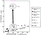
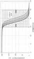
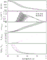
Fig. 1 illustrates particle confinement under a high performance FRC regime (HPF) in the present FRC system relative to a conventional FRC regime (CR) and relative to other conventional FRC experiments.
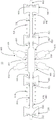
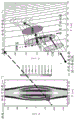
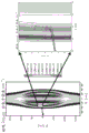
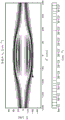
Fig. 2 illustrates components of the present FRC system and the magnetic topology of FRCs that may be produced in the present FRC system.
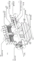
Fig. 3A illustrates the basic layout of the present FRC system when viewed from the top, including the preferred arrangement of central confinement vessel, generation section, divertor, neutral beam, electrodes, plasma gun, mirror plug and pellet injector.
Fig. 3B illustrates the central confinement vessel when viewed from the top, and shows neutral beams arranged at an angle orthogonal to the main axis of symmetry in the central confinement vessel.
Fig. 3C illustrates the central confinement vessel when viewed from the top, and shows a neutral beam arranged at an angle less than orthogonal to the main axis of symmetry in the central confinement vessel and directed to inject particles towards the mid-plane of the central confinement vessel.
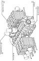
Fig. 3D and 3E illustrate top and perspective views, respectively, of the basic layout of an alternative embodiment of the present FRC system, including the preferred arrangement of the central confinement vessel, generation section, inner and outer divertors, neutral beams, arranged at an angle less than normal to the main symmetry axis of the central confinement vessel, electrodes, plasma gun and mirror plug.
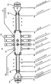
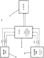
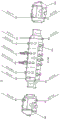
Fig. 4 illustrates a schematic diagram of components of a pulsed power system that generates a portion.
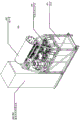
Fig. 5 illustrates an isometric view of an individual pulse power forming sled (ski).
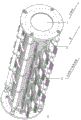
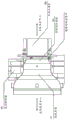
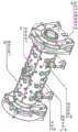
Figure 6 illustrates an isometric view of the generator tube assembly.
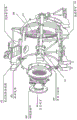
FIG. 7 illustrates a partial cross-sectional isometric view of the neutral beam system and key components.
Fig. 8 illustrates an isometric view of a neutral beam arrangement on a confinement chamber.
Figure 9 illustrates a partial cross-sectional isometric view of a preferred arrangement of a titanium and lithium getter system.
FIG. 10 illustrates a partial cross-sectional isometric view of a plasma gun installed in a divertor chamber. Associated magnetic mirror plugs and divertor electrode assemblies are also shown.
FIG. 11 illustrates a preferred layout of annular biasing electrodes at the axial ends of the confinement chamber.
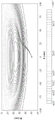
Fig. 12 illustrates the evolution of the excluded flux radius in an FRC system obtained from a series of external diamagnetic loops at two reversed-field-theta-ping generation sections and a magnetic probe embedded within a central metallic confinement chamber. Time is measured from the moment the sync field in the generating source reverses direction and the distance z is given relative to the axial mid-plane of the machine.
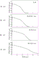
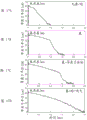
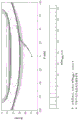
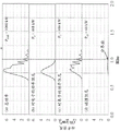
Fig. 13A, 13B, 13C, and 13D illustrate data from a representative non-HPF, unsupported discharge on the present FRC system. Shown as a function of time are (fig. 13A) the exclusion flux radius at the mid-plane, (fig. 13B) 6 chords of line integration density from the mid-plane CO2 interferometer, (fig. 13C) abelian inverted density radial distribution from the CO2 interferometer data, and (fig. 13D) the total plasma temperature from pressure equilibrium.
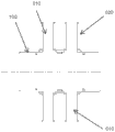
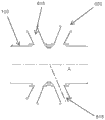
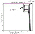
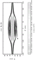
Fig. 14 illustrates the excluded flux axial distribution at selected times for the same discharge of the present FRC system shown in fig. 13A, 13B, 13C and 13D.
Fig. 15 illustrates an isometric view of a saddle coil mounted outside a restraint chamber.
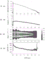
Fig. 16A, 16B, 16C and 16D illustrate the dependence of FRC lifetime and pulse length of the injected neutral beam. As shown, longer beam pulses produce longer surviving FRCs.
Fig. 17A, 17B, 17C and 17d, the individual and combined effects of the different components of the FRC system on the FRC performance and the achievement of the HPF mechanism.
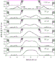
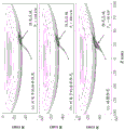
Fig. 18A, 18B, 18C, and 18D illustrate data from a representative HPF, unsupported discharge on the present FRC system. Shown as a function of time are (fig. 18A) the exclusion flux radius at the mid-plane, (fig. 18B) 6 chords of line integration density from the mid-plane CO2 interferometer, (fig. 18C) abelian inverted density radial distribution from the CO2 interferometer data, and (fig. 18D) the total plasma temperature from pressure equilibrium.
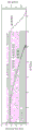
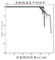
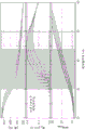
Fig. 19 illustrates the flux constraints as a function of electron temperature (Te). It represents a graphical illustration of the newly established superior scaling (scaling) mechanism of HPF discharge.
Fig. 20 illustrates FRC lifetimes corresponding to pulse lengths of non-angled and angled injected neutral beams.
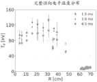
Fig. 21A, 21B, 21C, 21D and 21E illustrate the pulse length and plasma radius of an angled injected neutral beam, the plasma density, the lifetime of FRC plasma parameters of the plasma temperature, and the magnetic flux corresponding to the pulse length of the angled injected neutral beam.
Fig. 22A and 22B illustrate the basic layout of a compact ring (CT) injector.
Fig. 23A and 23B illustrate a central containment vessel showing a CT injector mounted to the central containment vessel.
Fig. 24A and 24B illustrate the basic layout of an alternative embodiment of a CT injector having a drift tube coupled thereto.
Figure 25 illustrates the central confinement vessel when viewed from the top and shows a neutral beam arranged and directed at an angle less than orthogonal to the main axis of symmetry in the central confinement vessel to inject particles towards the mid-plane of the central confinement vessel, and shows an antenna from which higher harmonic fast waves propagate at an angle less than orthogonal to the main axis of symmetry in the central confinement vessel and are directed to propagate from the mid-plane of the central confinement vessel for heating plasma electrons.
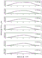
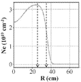
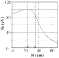
Fig. 26A and 26B illustrate the complete radial density distribution and the complete radial electron temperature distribution of the FRC plasma of the present FRC system.
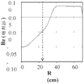
Fig. 27A-27D illustrate the radial distribution of system balance and eigenfrequencies at the mid-plane (Z = 0) of the present FRC system.
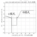
Fig. 28A-28C illustrate observations of power absorption and mode conversion in an FRC plasma of the present FRC system under electronic heating conditions of microwaves at 8 GHz.
Fig. 29A-29F illustrate observations of power absorption and mode conversion in an FRC plasma of the present FRC system under electronic heating conditions of microwaves at 50 GHz.
Fig. 30A-30C illustrate observations of power absorption in an FRC plasma of the present FRC system under electrical heating conditions with whistle waves at 0.5 GHz.
Fig. 31 illustrates density distribution and wave propagation in an FRC plasma of the present FRC system.
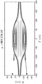
Fig. 32 illustrates poloidal flux distribution and wave propagation in the FRC plasma of the present FRC system.
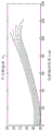
Fig. 33 illustrates exemplary density distributions and wave propagation trajectories in an FRC plasma of the present FRC system.
FIG. 34 illustrates an exemplary in FRC plasma of the present FRC systemω/ω ci[D] Distribution and wave propagation trajectories.
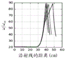
Fig. 35 illustrates exemplary power damping in an FRC plasma of the present FRC system with wave propagation distance.
Fig. 36 illustrates exemplary power absorption densities in an FRC plasma of the present FRC system.
Fig. 37A and 37B illustrate exemplary radial distributions of power density in the FRC plasma of the present FRC system.
Fig. 38 illustrates an exemplary 2D distribution of damping power density in an FRC plasma of the present FRC system.
Fig. 39 illustrates an exemplary power damping profile in an FRC plasma of the present FRC system.
Fig. 40 illustrates an exemplary finite ion larmor radius distribution in an FRC plasma of the present FRC system.
Fig. 41 illustrates an exemplary power absorption profile in an FRC plasma of the present FRC system.
Fig. 42 illustrates an exemplary distribution of FRC plasma of the present FRC system.
It should be noted that the figures are not necessarily drawn to scale and that elements of similar structure or function are generally represented by like reference numerals throughout the figures for illustrative purposes. It should also be noted that the figures are only intended to facilitate the description of the various embodiments described herein. The drawings do not necessarily depict every aspect of the teachings disclosed herein and do not limit the scope of the claims.
Detailed Description
The present embodiments provided herein relate to systems and methods that facilitate the formation and maintenance of FRCs with excellent stability and particle, energy, and flux constraints. Some of the present embodiments relate to systems and methods that utilize neutral beam injection and higher harmonic fast wave electron heating to facilitate the formation and maintenance of FRCs with elevated system energies and temperatures and improved support.
Representative examples of the embodiments described herein, which utilize many of these additional features and teachings both separately and in combination, will now be described in more detail with reference to the appended drawings. This detailed description is merely intended to teach a person of ordinary skill in the art further details for practicing preferred aspects of the present teachings and is not intended to limit the scope of the invention. Therefore, combinations of features and steps disclosed in the following detailed description may not be necessary to practice the invention in the broadest sense, and are instead taught merely to particularly describe representative examples of the present teachings.
Furthermore, various features of the representative examples and the dependent claims may be combined in ways that are not specifically and explicitly enumerated in order to provide additional useful embodiments of the present teachings. Furthermore, it is expressly noted that all features disclosed in the description and/or the claims are intended to be disclosed separately and independently from each other for the purpose of original disclosure, as well as for the purpose of restricting the claimed subject matter independently of the composition of the features in the embodiments and/or the claims. It is also expressly noted that all indications of value ranges or groups of entities disclose every possible intermediate value or intermediate entity for the purpose of original disclosure as well as for the purpose of limiting the claimed subject matter.
Before turning to systems and methods that facilitate higher harmonic fast wave electron heating in FRC plasmas, a discussion of systems and methods for forming and maintaining high performance FRCs with superior stability and superior particle, energy, and flux constraints compared to conventional FRCs, as well as systems and methods for forming and maintaining high performance FRCs at or about a constant value without attenuation, is provided. Such high performance FRCs provide access to a wide variety of applications, including compact neutron sources (for medical isotope production, nuclear waste remediation, materials research, neutron radiography, and tomography), compact photon sources (for chemical production and processing), mass separation and concentration systems, and reactor cores for photonuclear fusion for future energy generation.
Various auxiliary systems and modes of operation have been developed to assess whether or not there are excellent constraint mechanisms in the FRC. These efforts have led to breakthrough discovery and the development of the high performance FRC paradigm described herein. According to this new paradigm, the present system and method combines a number of novel concepts and means to significantly improve FRC constraints as shown in fig. 1, as well as provide stability control without negative side effects. As discussed in more detail below, fig. 1 depicts particle confinement in the FRC system 10 described below (see fig. 2 and 3), as compared to operating according to the conventional mechanism CR for forming and maintaining an FRC used in other experiments, and as compared to particle confinement according to the conventional mechanism for forming and maintaining an FRC, operating according to a High Performance FRC (HPF) mechanism for forming and maintaining an FRC. The present disclosure will outline and detail the innovative individual components of the FRC system 10 and method and their combined roles.
FRC system
Vacuum system
Fig. 2 and 3 depict schematic diagrams of the present FRC system 10. The FRC system 10 includes a central containment vessel 100 surrounded by two diametrically opposed reverse field angle pinch generating sections 200, and two divertor chambers 300 outside the generating sections 200, the divertor chambers 300 being used to control neutral density and impurity contamination. The present FRC system 10 is constructed to accommodate ultra-high vacuum and is designed to accommodate the ultra-high vacuum at 10 -8 Typical base pressure operation of torr. This vacuum pressure requires the use of double pumped mating flanges between mating parts, metal O-rings, high purity inner walls, and careful initial surface treatment of all parts prior to assembly, such as physical and chemical cleaning, followed by vacuum baking at 24 hours 250 ℃ and hydrogen glow dischargeAnd (4) cleaning.
The inverse field-oriented pinch generating section 200 is a standard inverse field-oriented pinch (FRTP), although with the advanced pulse power generation system discussed in detail below (see fig. 4-6). Each generation section 200 is made of standard opaque technical grade quartz tubing that includes the feature of a 2 mm ultra pure quartz liner. The confinement chamber 100 is made of stainless steel to allow for multiple radial and tangential ports; it also serves as a flux keeper (flux concentrator) on the time scale of the experiments described below and limits fast magnetic transients. A vacuum is created and maintained within FRC system 10 by a set of dry scroll roughing pumps, turbo molecular pumps and cryopumps.
Magnetic system
A magnetic system 400 is illustrated in fig. 2 and 3. Fig. 2 illustrates, among other features, FRC magnetic flux and isopycnic lines (as a function of radial and axial coordinates) pertaining to FRC 450 that may be produced by FRC system 10. These isopycnic lines are obtained by 2-D resistive Hall-MHD digital simulation using code developed to simulate the system and method corresponding to the FRC system 10 and are in considerable agreement with measured experimental data. As seen in fig. 2, the FRC 450 includes a ring of closed field lines at the interior 453 of the FRC 450 within the separatrix 451, and an annular edge layer 456 on the open field lines 452 just outside the separatrix 451. The edge layers 456 merge into the jet 454 outside the FRC length, providing a natural divertor.
The main magnet system 410 includes a series of quasi-dc coils 412, 414, and 416 located at specific axial positions along the components of the FRC system 10 (i.e., along the confinement chamber 100, the generation section 200, and the divertor 300). The quasi-dc coils 412, 414, and 416 are fed by a quasi-dc switching power supply and produce a fundamental magnetic bias field of about 0.1T in the confinement chamber 100, the generation section 200, and the divertor 300. In addition to the quasi-dc coils 412, 414 and 416, the main magnet system 410 also includes quasi-dc mirror coils 420 (fed by a switching power supply) between either end of the confinement chamber 100 and the adjacent generation section 200. The quasi-dc mirror coils 420 provide a magnetic mirror ratio of up to 5 and can be independently energized for balanced shaping control. In addition, a mirror plug 440 is positioned between the generation part 200 and each of the divertors 300. The mirror plug 440 includes a compact quasi-dc mirror coil 430 and a mirror plug coil 444. Quasi-dc mirror coil 430 includes three coils 432, 434, and 436 (fed by switching power supplies) that generate additional guiding fields to focus magnetic flux surface 455 toward small diameter channel 442 through mirror plug coil 444. A mirror plug coil 444 wrapped around the small diameter channel 442 and fed by an LC pulse power supply circuit generates a strong mirror field of up to 4T. The purpose of this overall coil arrangement is to tightly bind and direct magnetic flux surface 455 and end-flowing plasma jet 454 into the remote chamber 310 of divertor 300. Finally, a set of saddle coil "antennas" 460 (see FIG. 15) are located outside the confinement chamber 100, two on each side of the mid-plane, and are fed by a DC power supply. The saddle coil antenna 460 may be configured to provide a quasi-static magnetic dipole or quadrupole field of about 0.01T for controlling rotational instability and/or electron flow control. Depending on the direction of the applied current, the saddle coil antenna 460 can flexibly provide a magnetic field that is either symmetric or anti-symmetric about the mid-plane of the machine.
Pulse power generation system
The pulse power generation system 210 operates based on a modified angular pinch principle. There are two systems that each provide energy to one of the generating portions 200. Fig. 4 to 6 illustrate the main building blocks and arrangements of the generation system 210. The generation system 210 includes a modular pulsed power arrangement that includes individual cells (= sleds) 220 that each excite a subset of the coils 232 of the ribbon assembly 230 (= ribbons), the ribbon assembly 230 being wrapped around the generation quartz tube 240. Each sled 220 includes a capacitor 221, an inductor 223, a fast high current switch 225 and associated flip-flop 222, and a dump circuit (dump circuit) 224. In general, each generation system 210 stores between 350-400 kJ of capacitive energy, which provides up to 35 GW of power to develop and accelerate the FRC. The cooperative operation of these components is achieved via state-of-the-art trigger and control systems 222 and 224, which allow synchronized timing on each production section 200 between production systems 210 and minimize switching jitter to tens of nanoseconds. The advantage of this modular design is its flexible operation: FRCs can be formed in situ and then accelerated and injected (= static formation) or formed and accelerated simultaneously (= dynamic formation).
Neutral beam injector
A neutral atom beam 600 is deployed on the FRC system 10 to provide heating and current drive as well as to create fast particle pressure. As shown in fig. 3A, 3B and 8, the individual beam lines include neutral atom beam injector systems 610 and 640 that are positioned around the central confinement chamber 100 and inject fast particles in collision parameters tangential to the FRC plasma (and perpendicular to or at an angle orthogonal to the main axis of symmetry in the central confinement vessel 100) so that the target trapping region is well within the separatrix 451 (see fig. 2). Each injector system 610 and 640 is capable of injecting up to 1MW of neutral beam power into an FRC plasma having particle energies between 20 and 40 keV. The systems 610 and 640 are based on positive ion multi-aperture extraction sources and utilize geometric focusing, inertial cooling of the ion extraction grid, and differential pumping. In addition to using different plasma sources, the systems 610 and 640 differ primarily in their physical design to meet their respective mounting locations, thereby creating side and top injection capabilities. Typical components of these neutral beam injectors are specifically illustrated in fig. 7 for a side injector system 610. As shown in fig. 7, each individual neutral beam system 610 includes an RF plasma source 612 at the input end (which is replaced with an arc source at system 640) with a magnetic shield 614 covering that end. An ion source and acceleration grid 616 is coupled to plasma source 612 and a gate valve 620 is positioned between ion source and acceleration grid 616 and neutralizer 622. The deflecting magnet 624 and the ion dump 628 are located between the neutralizer 622 and the aiming feature 630 at the exit end. The cooling system includes two cryocoolers 634, two cryopanels 636, and an LN2 hood 638. This flexible design allows operation over a wide range of FRC parameters.
An alternative configuration for the neutral atom beam injector 600 is one in which: fast particles are injected tangentially to the FRC plasma but at an angle a of less than 90 ° with respect to the main axis of symmetry in the central confinement vessel 100. These types of orientations of beam injectors 615 are shown in fig. 3C. Additionally, the beam injectors 615 may be oriented such that the beam injectors 615 on either side of a mid-plane of the central confinement vessel 100 inject their particles toward the mid-plane. Finally, the axial position of these beam systems 600 may be selected to be closer to the mid-plane. These alternative implantation embodiments facilitate a more central loading option, which provides better coupling of the beam and higher capture efficiency of the fast particles being implanted. Furthermore, depending on the angle and axial position, this arrangement of beam injectors 615 allows for more direct and independent control of the axial elongation and other features of the FRC 450. For example, injecting a beam at a shallow angle a relative to the vessel's main axis of symmetry will produce an FRC plasma with a longer axial extension and lower temperature, while choosing a more perpendicular angle a will result in an axially shorter but hotter plasma. In this way, the implantation angle a and position of the beam injector 615 may be optimized for different purposes. In addition, such angling and positioning of the beam injector 615 may allow beams with higher energies (which is generally more advantageous for depositing more power with less beam divergence) to be injected into a lower magnetic field than would otherwise be necessary to capture such beams. This is due to the fact that: what determines the fast ion trajectory dimension (which becomes progressively smaller as the implantation angle relative to the main axis of symmetry of the vessel decreases at constant beam energy) is the azimuthal component of the energy. Furthermore, implantation angled toward the mid-plane and with the axial beam position near the mid-plane improves beam-plasma coupling, even when the FRC plasma shortens (shrink) or otherwise axially contracts during the implant period.
Turning to fig. 3D and 3e, another alternative configuration of frc system 10 includes an inner divertor 302 in addition to angled beam injectors 615. The inner divertor 302 is positioned between the generation section 200 and the confinement chamber 100, and is constructed and operates substantially similar to the outer divertor 300. The internal divertor 302, which includes a fast switching magnetic coil, is effectively idled during the formation process, so that the generation FRC (format FRC) can pass through the internal divertor 302 as it moves toward the mid-plane of the confinement chamber 100. Once the production FRC has passed through the inner divertor 302 into the confinement chamber 100, the inner divertor is activated to operate substantially similar to the outer divertor and isolate the confinement chamber 100 from the production section 200.
Pill injector
To provide a means of injecting new particles and better controlling the FRC particle inventory, a 12-barrel Pellet injector 700 is employed on the FRC system 10 (see, e.g., "Pellet Injectors Developed at PELIN for JET, TAE, and HL-2A" by i. Vinyar et al, proceedings of 26 th nuclear fusion science and technology society, 09/27 to 10/01 (2010)). Fig. 3 illustrates the layout of the bolus injector 700 on the FRC system 10. Cylindrical pellets (D-1 mm, L-1-2 mm) were injected into the FRC at a velocity in the range of 150-250 km/s. Each individual projectile contains approximately 5 x 10 19 Hydrogen atoms, which correspond to the FRC particle inventory.
Air suction system
It is well known that neutral halo gases are a serious problem in all restraint systems. The charge exchange and recovery (release of cold contaminant material from the walls) process can have a devastating effect on energy and particle confinement. In addition, any large density of neutral gas at or near the edges will result in a rapid loss of injected large orbital (high energy) particles or at least a severe shortening of their lifetime (large orbits refers to particles having orbits on the scale of the FRC topology, or at least having orbital radii much larger than the characteristic magnetic field gradient length scale), a fact that is disadvantageous for all high energy plasma applications, including nuclear fusion via auxiliary beam heating.
Surface treatment is a means by which the adverse effects of neutral gases and impurities can be controlled or reduced in a containment system. The FRC system 10 provided herein employs for this purpose titanium and lithium deposition systems 810 and 820 that coat the plasma-facing surfaces of the confinement chamber (or vessel) 100 and divertors 300 and 302 with a film (tens of microns thick) of titanium and/or lithium. The coating is achieved via a vapor deposition technique. Solid lithium and/or titanium is evaporated and/or sublimated and sprayed onto nearby surfaces to form a coating. The source is a nuclear furnace with a pilot nozzle (in the case of lithium) 822 or a heated solid sphere with a pilot shroud (in the case of titanium) 812. Lithium vaporizer systems typically operate in a continuous mode while titanium sublimers operate mostly intermittently between plasma operations. The operating temperature of these systems is above 600 ℃ to obtain fast deposition rates. In order to achieve good wall coverage, multiple strategically positioned evaporator/sublimator systems are necessary. Fig. 9 shows in detail a preferred arrangement of getter deposition systems 810 and 820 in FRC system 10. The coating acts as a getter surface and efficiently pumps hydrogen species atoms and molecular species (H and D). The coating also reduces other typical impurities such as carbon and oxygen to insignificant levels.
Mirror plug
As described above, FRC system 10 employs sets of mirror coils 420, 430, and 444 as shown in fig. 2 and 3. The first set of mirror coils 420 are located at both axial ends of the confinement chamber 100 and are energized independently of the dc confinement, formation and divertor coils 412, 414, 416 of the main magnet system 410. The first set of mirror coils 420 primarily helps guide and axially contain the FRC 450 during consolidation and provides balanced shaping control during support. The first mirror coil set 420 produces a nominally higher magnetic field (about 0.4 to 0.5T) than the central confinement field produced by the central confinement coil 412. A second set of mirror coils 430, comprising three compact quasi-dc mirror coils 432, 434 and 436, is located between the generating section 200 and the divertor 300 and is driven by a common switching power supply. The mirror coils 432, 434 and 436 together with the more compact pulsed mirror plug coil 444 (fed by the capacitive power supply) and the physical constriction 442 form a mirror plug 440 that provides a narrow low gas conduction path with a very high magnetic field (between 2 to 4T and a rise time of about 10 to 20 ms). The most compact pulse mirror coil 444 has a compact radial dimension, a 20cm aperture, and similar length compared to the one meter-plus-scale (meter-plus-scale) aperture and pancake design of the confinement coils 412, 414, and 416. The purpose of the mirror plug 440 is multiple: (1) The coils 432, 434, 436, and 444 are closely bundled and guide the magnetic flux surface 452 and the end-stream plasma jet 454 into the remote divertor chamber 300. This ensures that the exhaust particles properly reach the divertor 300 and there is a continuous flux surface 455 up to the divertor 300 from the area of the open field lines 452 of the central FRC 450. (2) The physical constriction 442 in the FRC system 10 provides an obstruction to the flow of neutral gas from the plasma gun 350 seated in the divertor 300, and the coils 432, 434, 436, and 444 pass the magnetic flux surface 452 and the plasma jet 454 through the physical constriction 442. Also, constriction 442 prevents backflow of gas from generation section 200 to divertor 300, thereby reducing the number of neutrals that must be introduced throughout FRC system 10 when starting up the FRC. (3) The strong axial mirror created by coils 432, 434, 436, and 444 reduces axial particle loss and thus reduces parallel particle diffusivity over open field lines.
In an alternative configuration shown in fig. 3D and 3E, a set of low profile necking coils 421 are positioned between the inner divertor 302 and the generation portion 200.
Axial plasma gun
The plasma flow from the gun 350 installed in the divertor chamber 310 of the divertor 300 is intended to improve stability and neutral beam performance. As shown in fig. 3 and 10, the gun 350 is mounted on an axis within the chamber 310 of the divertor 300 and generates a plasma that flows in the divertor 300 along the open flux lines 452 and toward the center of the confinement chamber 100. The gun 350 operates with a high density gas discharge in the gasket stack channel and is designed to generate a fully ionized plasma of thousands of amps for 5 to 10 ms. The gun 350 includes a pulsing magnetic coil that matches the output plasma flow to the desired size of the plasma in the confinement chamber 100. The technical parameters of the gun 350 are characterized by a channel having an outer diameter of 5 to 13 cm and an inner diameter of up to about 10 cm and providing a discharge current of 10-15 kA at 400-600V with an in-gun magnetic field of between 0.5 and 2.3T.
The gun plasma stream may pass through the magnetic field of the lens plug 440 and flow into the generation portion 200 and the confinement chamber 100. As the distance between the gun 350 and the plug 440 decreases and by making the plug 440 wider and shorter, through the scope plug 44The efficiency of the plasma transfer of 0 increases. Under reasonable conditions, the gun 350 can deliver about 10 eV each at high ion and electron temperatures of about 150 to 300 eV and about 40 to 50eV, respectively 22 The protons/s pass through a 2 to 4T mirror plug 440. The gun 350 provides significant recharging of the FRC edge layer 456, as well as improved overall FRC particle confinement.
To further increase the plasma density, a gas box may be utilized to inject additional gas into the plasma stream from the gun 350. This technique allows for a multiple increase in the density of the injected plasma. In the FRC system 10, the gas box mounted on the divertor 300 side of the mirror plug 440 improves the recharging of the FRC edge layer 456, the formation of the FRC 450, and the plasma-wiring (line-typing).
It is readily apparent that a wide range of operating modes may be obtained, taking into account all the adjustment parameters discussed above and also taking into account that operation with only one gun or with two guns is possible.
Bias electrode
The electrical bias of the open flux surface may provide a radial potential that causes azimuthal angle E x B motion, which provides a control mechanism similar to a turning knob to control the open field line plasma and rotation of the actual FRC core 450 via velocity shear. To achieve this control, FRC system 10 employs various electrodes strategically placed in various portions of the machine. Fig. 3 depicts the biasing electrodes positioned at preferred locations within FRC system 10.
In principle, there are 4 types of electrodes: (1) point electrodes 905 in the confinement chamber 100 that contact specific open field lines 452 in the edge of the FRC 450 to provide local charging, (2) ring electrodes 900 between the confinement chamber 100 and the generation section 200 to charge the distal edge flux layer 456 in an azimuthally symmetric manner, (3) a stack of concentric electrodes 910 in the divertor 300 to charge multiple concentric flux layers 455 (where the selection of layers is controllable by adjusting the coils 416 to adjust the divertor magnetic field to terminate the desired flux layer 456 on the appropriate electrode 910), and finally (4) the anode 920 (see fig. 10) of the plasma gun 350 itself (which intercepts the open flux surface 455 near the interface of the FRC 450). Fig. 10 and 11 show some typical designs for some of these electrodes.
In all cases, the electrodes are driven by a pulsed or direct current power supply at a voltage of up to about 800V. Depending on the electrode size and with which flux surface current in the kilo-amperes range can be drawn.
Unsupported operation-conventional mechanism for FRC systems
Standard plasma formation on the FRC system 10 follows the well-developed reverse field-angle pinch technique. A typical process for starting the FRC begins by driving the collimating coils 412, 414, 416, 420, 432, 434, and 436 to steady state operation. The RFTP pulse power circuit of the pulse power generation system 210 then drives the pulsed fast reverse magnetic field coil 232 to produce a temporary reverse bias voltage of about-0.05T in the generation portion 200. At this time, a predetermined amount of neutral gas is injected into the two forming volumes defined by the quartz tube chambers 240 of the (north and south) generating section 200 at 9-20 psi via a set of azimuthally oriented charging valleys (puff-vale) at flanges located on the outer ends of the generating section 200. Next, a small RF (-hundreds of kilohertz) field is generated from a set of antennas on the surface of quartz tube 240 to produce pre-ionization in the form of a localized seed ionization region (seed ionization region) within the neutral gas column. This is followed by applying a theta-ringing modulation on the current driving the pulsed fast reversal field coil 232, which results in a more comprehensive pre-ionization of the gas column. Finally, the main set of pulsed power of the pulsed power generation system 210 is activated to drive the pulsed fast reverse magnetic field coil 232, producing a forward bias field of up to 0.4T. This step may be chronological such that the forward bias field is generated uniformly throughout the length of the generation tube 240 (static formation), or such that continuous peristaltic field modulation is achieved along the axis of the generation tube 240 (dynamic formation).
During this entire formation, the actual field reversal in the plasma occurs rapidly within about 5 μ s. The multi-megawatt pulsed power delivered to the forming plasma readily produces a hot FRC that is then ejected from the generating section 200 via time-sequential modulation of the applied forward magnetic field (magnetic peristalsis) or a temporarily increased current in the last coil of the coil set 232 near the axially outer end of the generating tube 210 (forming an axial magnetic field gradient that is directed axially toward the confinement chamber 100). The two (north and south) generating FRCs thus formed and accelerated then expand into the larger diameter confinement chamber 100 where the collimating current coils 412 produce a forward bias field to control radial expansion and provide balanced external magnetic flux in the confinement chamber 100.
Once the north and south generating FRCs reach near the mid-plane of the confinement chamber 100, the FRCs collide. During a collision, the axial kinetic energy of the north and south generated FRCs is largely thermalized as the FRCs eventually merge into a single FRC 450. A large set of plasma diagnostics is available in the confinement chamber 100 to study the balance of the FRC 450. Typical operating conditions in FRC system 10 produce a composite FRC having a separatrix radius of about 0.4 m and an axial extent of about 3 m. Further characterized by an external magnetic field of about 0.1T, about 5X 10 19 m -3 And a total plasma temperature of up to 1 keV. Without any support, i.e., without heating and/or current driving via neutral beam injection or other auxiliary means, the lifetime of these FRCs is limited to about 1 ms, intrinsic feature configuration decay time.
Experimental data-conventional mechanism for unsupported operation
FIG. 12 shows a typical time evolution excluding the flux radius r, which is close to the interface radius r s To illustrate the dynamics of the angular pinch merging process of the FRC 450. Two (north and south) separate plasmoids are generated simultaneously and then at supersonic velocity v Z 250 km/s are accelerated away from the respective generating portion 200 and collide at z = 0 near the mid-plane. The plasmoids compress axially during collisions, followed by rapid radial and axial expansion, and then eventually merge to form the FRC 450. Combining radial and axial dynamics of FRC 450 through detailed density splittingCloth measurements and bolometer-based tomography.
Data from a representative unsupported discharge of FRC system 10 is shown as a function of time in fig. 13A, 13B, 13C, and 13D. FRC starts at t = 0. The excluded flux radius at the axial mid-plane of the machine is shown in fig. 13A. This data is obtained from an array of magnetic probes located just inside the stainless steel wall of the confinement chamber, which measure the axial magnetic field. The steel wall is a good flux holder on the time scale of this discharge.
The line integral density is shown in fig. 13B, from a 6 chord CO at z = 0 2 A/He-Ne interferometer. Considering the vertical (y) FRC shift, the Abel inversion produces the isopycnic line of fig. 13C as measured by bolometric tomography. After some axial and radial shaking during the first 0.1 ms, the FRC stabilizes with a hollow density profile. This distribution is fairly flat with a fairly large density on axis, as required by typical 2-D FRC balance.
The total plasma temperature, which results from pressure equilibrium and is in full agreement with thomson scattering and spectroscopy measurements, is shown in fig. 13D.
Analysis from the entire exclusion flux array indicated that the shape of the FRC interface (approximated by the exclusion flux axial distribution) evolves gradually from a racetrack shape to an ellipse. This evolution shown in fig. 14 is consistent with a gradual magnetic reconnection from two to a single FRC. In fact, a rough estimate indicates that in this particular case approximately 10% of the two initial FRC flux reconnects during the collision.
The FRC length steadily shortens from 3m to about 1m during the FRC lifetime. This shortening, as can be seen from fig. 14, indicates that the FRC constraint is dominated by energy losses that are primarily convective. Since the plasma pressure in the interface drops faster than the external magnetic pressure, the magnetic field line tension in the end region compresses the FRC axially, restoring axial and radial balance. For the discharges discussed in fig. 13 and 14, FRC magnetic flux, particle inventory, and thermal energy (approximately 10 mwb,7 x 10, respectively) appear to subside when FRC equilibrium appears to subside 19 One particle and 7 kJ) is reduced by about one in the first millisecondSeveral orders of magnitude.
Supported operations-HPF mechanism
The examples in fig. 12-14 are features of an attenuating FRC without any support. However, several techniques are deployed on FRC system 10 to further improve FRC constraints (inner core and edge layers) to the HPF mechanism and support this configuration.
Neutral beam
First, the fast (H) neutral particles are perpendicular to B z Injected with beams from eight neutral beam injectors 600. The fast neutral beam generated FRCs from north and south are injected at the time when the beams merge into one FRC 450 in the confinement chamber 100. The fast ions generated primarily by charge exchange have betatron orbits (with a major radius on the scale of the FRC topology or at least much larger than the characteristic magnetic field gradient length scale) that increase the azimuthal current of the FRC 450. After a partial discharge (0.5 to 0.8 ms after going into emission), sufficiently large fast ion populations significantly improve the stability and confinement properties of the internal FRC (see, e.g., m.w. Binder and n. Rotoker, plasma phys. 56, part 3, 451 (1996)). Furthermore, from a support perspective, the beam from the neutral beam injector 600 is also the primary means for driving the current and heating the FRC plasma.
In the plasma regime of FRC system 10, fast ions are slowed primarily on plasma electrons. The typical orbit average slow down time for fast ions is 0.3-0.5 ms in the early part of the discharge, which results in significant FRC heating of mainly electrons. Fast ions produce large radial drift outside the interface because the internal FRC magnetic field is inherently low (about 0.03T on average for an external axial field of 0.1T). Fast ions will be susceptible to charge exchange losses if the neutral gas density is too high outside the interface. Thus, wall gettering and other techniques deployed on FRC system 10 (such as plasma gun 350 and mirror plug 440, which, among other things, facilitate gas control) tend to minimize edge neutrals and enable the desired establishment of a fast ion stream.
Shot injection
When a significant fast ion population is established within the FRC 450, frozen H or D shot is injected from the shot injector 700 into the FRC 450 at higher electron temperatures and longer FRC lifetimes to support the FRC particle inventory of the FRC 450. The desired ablation time scale is sufficiently short to provide a large number of FRC particle sources. This velocity may also be increased by enlarging the surface area of the injector by breaking individual projectiles into smaller pieces as they enter the injection tube or barrel of the projectile injector 700 and prior to entering the confinement chamber 100, a step which may be achieved by increasing the friction between the projectiles and the wall of the injection tube by tightening the bend radius of the final section of the injection tube just prior to entering the confinement chamber 100. By varying the activation sequence and speed of the 12 barrels (injection tubes) and fragmentation, it is possible to tune the shot injection system 700 to provide just the desired level of particle inventory support. This, in turn, helps maintain internal dynamic pressure in the FRC 450 and supported operation and life of the FRC 450.
Once the ablated atoms encounter a large amount of plasma in the FRC 450, they become fully ionized. The resulting cold plasma constituent is then collisionally heated by the intrinsic FRC plasma. The energy necessary to maintain the desired FRC temperature is ultimately supplied by the beam injector 600. In this sense the projectile injector 700 forms a system with the neutral beam injector 600 that maintains a steady state and supports the FRC 450.
CT injector
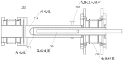
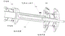
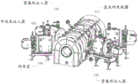
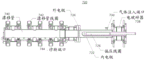
As an alternative to the pellet injector, a compact ring (CT) injector is provided, primarily for charging Field Reversed Configuration (FRC) plasma. The CT injector 720 includes a Magnetized Coaxial Plasma Gun (MCPG), as shown in fig. 22A and 22B, which includes coaxial cylindrical inner and outer electrodes 722, 724, a bias coil 726 positioned inside the inner electrode, and an electrical breaker (electrical break) 728 on the opposite end of the discharge of the CT injector 720. Gas is injected into the space between the inner and outer electrodes 722, 724 through a gas injection port 730, and a spheromak-like plasma is thereby generated by the discharge and propelled from the gun by the lorentz force. As shown in fig. 23A and 23B, a pair of CT injectors 720 are coupled to the confinement vessel 100 near a mid-plane of the vessel 100 and on opposite sides of the mid-plane to inject CTs into the central FRC plasma within the confinement vessel 100. Similar to the neutral beam injectors 615, the discharge ends of the CT injectors 720 are directed at an angle relative to the longitudinal axis of the containment vessel 100 toward the mid-plane of the containment vessel 100.
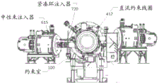
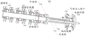
In an alternative embodiment, as shown in fig. 24A and 24B, the CT injector 720 includes a drift tube 740, the drift tube 740 comprising an elongated cylindrical tube coupled to the discharge end of the CT injector 720. As depicted, the drift tube 740 includes drift tube coils 742 positioned around and axially spaced along the tube. A plurality of diagnostic ports 744 are depicted along the length of the tube.
The advantages of the CT injector 720 are: (1) Control and adjustability of particle inventory via implanted CT; (2) Depositing a hot plasma (rather than a frozen pellet); (3) The system may be operated in a repetition rate (rep-rate) mode to allow for continuous dosing; (4) The system can also recover some of the magnetic flux because the injected CT carries the embedded magnetic field. In an example for experimental use, the inner diameter of the outer electrode was 83.1 mm and the outer diameter of the inner electrode was 54.0 mm. The surface of the inner electrode 722 is preferably coated with tungsten to reduce impurities coming out of the electrode 722. As depicted, a bias coil 726 is mounted within the inner electrode 722.
In recent experiments, supersonic CT moving speed as high as 100 km/s is realized. Other typical plasma parameters are as follows: an electron density of 5X 10²¹ m-3, an electron temperature of 30-50 eV, and a particle inventory of 0.5-1.0X 10¹⁹. The high dynamic pressure of the CT allows the injected plasma to penetrate deep into the FRC and deposit particles within the interfaces. FRC particle dosing in recent experiments has resulted in providing an FRC particle inventory of 10-20% by CT injectors, which successfully demonstrated that dosing can be easily performed without disrupting the FRC plasma.
Saddle coil
To achieve steady state current drive and maintain the required ion current, it is desirable to preventThe spin acceleration of electrons due to electron-ion friction (caused by ion electron momentum transfer due to collisions) is stopped or significantly reduced. FRC system 10 utilizes innovative techniques to provide electron fragmentation via externally applied static magnetic dipoles or quadrupole fields. This is achieved via the external saddle coil 460 depicted in fig. 15. The transverse applied radial magnetic field from saddle coil 460 induces an axial electric field in the rotating FRC plasma. The resulting axial electron flow interacts with the radial magnetic field, thereby producing an azimuthal fracturing force on the electrons, F θ =-σV eθ ‹∣B r ∣ 2 8250j. For typical conditions in the FRC system 10, the magnetic dipole (or quadrupole) field that needs to be applied within the plasma need only be on the order of 0.001T to provide sufficient electron fragmentation. The corresponding external field of about.015T is small enough not to cause significant fast particle loss or otherwise negatively affect confinement. In effect, the applied magnetic dipole (or quadrupole) field helps to suppress instability. In combination with tangential neutral beam injection and axial plasma injection, the saddle coil 460 provides an additional level of control with respect to current maintenance and stability.
Mirror plug
The design of the pulse coil 444 within the mirror plug 440 allows for the local generation of high magnetic fields (2 to 4T) with modest (approximately 100 kJ) capacitive energy. To create a magnetic field typical of the present operation of the FRC system 10, all of the field lines within the volume are created to pass through the constriction 442 at the mirror plug 440, as indicated by the magnetic field lines in fig. 2, and no plasma wall contact occurs. In addition, the mirror plug 440 in series with the collimated flow divertor magnet 416 can be adjusted to direct the field lines onto the divertor electrode 910, or to splay the field lines in an end cusp (cusp) configuration (not shown). The latter improves stability and inhibits parallel electron thermal conduction.
The mirror plug 440 itself also contributes to neutral gas control. The mirror plug 440 allows better utilization of deuterium gas that is charged into the quartz tube during FRC formation, since the gas back flow into the divertor 300 is significantly reduced by the small gas conductance of the plug (500L/s, slightly thinner). A substantial portion of the residual charge gas within the generation tube 210 is rapidly ionized. In addition, the high density plasma flowing through the mirror plug 440 provides effective neutral ionization and thus an effective gas barrier. As a result, a majority of the neutrals recovered from the FRC edge layer 456 in the divertor 300 do not return into the confinement chamber 100. Additionally, neutrals (discussed below) associated with the operation of the plasma gun 350 will be mostly confined in the divertor 300.
Finally, the mirror plug 440 is intended to improve FRC edge layer constraints. With a mirror ratio (plug/confinement field) in the range of 20 to 40, and with a length of 15m between the north and south mirror plugs 440, the edge layer particle confinement time Is increased by up to an order of magnitude. Improvements in or relating to
 FRC ion confinement is easily increased.
Assuming radial diffusion (D) particle losses from interface volume 453 are lost by axial losses from edge layer 456: ( ) Equilibrate to obtain
 Whereby the interface density gradient length can be rewritten as
 . Where r is s 、L s And n s The interface radius, the interface length and the interface density, respectively. FRC particle confinement time is
 In which
 And is provided with
 . Physically, improve
 Resulting in increased δ (reduced interface density gradient and drift parameters) and hence reduced FRC particle loss. The overall improvement in FRC particle confinement is typically slightly less than quadratic, since n s Followed by
 And (4) increasing.

Plasma gun
The plasma gun 350 improves the stability of the FRC discharge jet 454 by the wire bundle. The gun plasma from the plasma gun 350 is generated without azimuthal momentum, which has proven useful in controlling FRC rotational instability. Thus the gun 350 is an effective means of controlling FRC stability without the need for older quadrupole stabilization techniques. As a result, the plasma gun 350 makes it possible to take advantage of the benefits of fast particles, or to use an advanced hybrid dynamics FRC mechanism as outlined in the present disclosure. Thus, the plasma gun 350 enables the FRC system 10 to operate with a saddle coil flow: this saddle coil flow is just enough to do electron fragmentation, but below a threshold that would lead to FRC instability and/or to significantly fast particle diffusion.
As mentioned in the lens plug discussion above, if can be significantly improved Then gun suppliedPlasma will lose velocity with edge layer particles (-10) 22 S) were equivalent. The lifetime of the gun generated plasma in the
 FRC system 10 is in the millisecond range. In practice, consider having n e ~ 10 13 cm -3 And an ion temperature of about 200eV, a gun plasma confined between the end mirror plugs 440. The capture length L and the mirror ratio R are about 15m and 20, respectively. The mean free path of ions due to coulomb collisions is λ ii ~ 6×10 3 cm, and, because of λ ii lnR/R <L, so the ions are confined in the gas dynamic mechanism. The plasma confinement time in this regime is τ gd ~ RL/2V s 2 ms, wherein V s Is the ion sound velocity. By comparison, for these plasma parameters, the conventional ion confinement time would be τ c ~ 0.5τ ii (lnR + (lnR) 0.5 ) 0.7 ms. In principle, the anomalous lateral diffusion can shorten the plasma confinement time. However, in FRC system 10, if we assume Bohm diffusivity, then the estimated lateral confinement time for the gun plasma is τ ⊥ > τ gd 2 ms. Thus, the gun will provide significant recharge of the FRC edge layer 456 as well as improved overall FRC particle confinement.
In addition, the gun plasma stream may be turned on in about 150 to 200 microseconds, which allows for use in FRC startup, movement, and incorporation into the confinement chamber 100. If turned on near t 0 (the beginning of the main group of FRCs (main bank)), the gun plasma helps support the FRC 450 which is dynamically formed and merged. The combined particle inventory from the generating FRC and from the gun is sufficient for neutral beam trapping, plasma heating and long term support. If turned on at t, which is in the range of-1 to 0 ms, the gun plasma may fill the quartz tube 210 with plasma or ionize the gas charged into the quartz tube, allowing the formation of an FRC with reduced or possibly even zero charge of gas. The latter may require a sufficiently cold generated plasma to allow rapid diffusion of the reverse bias magnetic field. If at t<On at-2 ms, the plasma current is available for 10 13 cm -3 Target plasma density filling the generating portion200 and about 1 to 3m of the forming and confinement region of the confinement chamber 100 3 Is used to determine the field line volume of the FRC, which is sufficient to allow a neutral beam to build up before the FRC arrives. The FRC may then be formed and moved into the resulting confinement vessel plasma. In this manner, the plasma gun 350 enables a wide variety of operating conditions and parameter regimes.
Electric bias
Control of the radial electric field distribution in the edge layer 456 benefits FRC stability and confinement in various ways. With the innovative biasing components deployed in the FRC system 10, it is possible to apply a variety of deliberate potential distributions to a set of open flux surfaces throughout the machine from regions completely outside of the central confinement region in the confinement chamber 100. In this manner, a radial electric field can be generated across the edge layer 456 just outside the FRC 450. These radial electric fields then change the azimuthal rotation of the edge layer 456 and achieve its confinement via E × B velocity shear. Thus, any differential rotation between the edge layer 456 and the FRC core 453 may propagate into the FRC plasma interior through shear. As a result, control edge layer 456 directly affects FRC core 453. In addition, this technique provides a direct means for controlling the onset and growth of instabilities, as free energy in the plasma rotation may also cause instabilities. In FRC system 10, appropriate edge biases provide effective control over open field line transmission and rotation, as well as FRC core rotation. The various provided positions and shapes of electrodes 900, 905, 910, and 920 allow for different sets of flux surfaces 455 to be controlled and at different and independent potentials. In this way a large number of combinations of different electric field configurations and strengths can be achieved, each with different characteristic effects on the plasma properties.
The key advantage of all these innovative biasing techniques lies in the fact that: the behaviour of the core and edge plasmas can be influenced from the complete outside of the FRC plasma, i.e. without the need to bring any physical components into contact with the central thermal plasma (contact will have a severe impact on energy, flux and particle losses). This has a significant beneficial effect on the performance and overall potential applications of the HPF concept.
Experimental data-HPF procedures
The injection of fast particles via the beam from the neutral beam gun 600 plays an important role in enabling the HPF mechanism. Fig. 16A, 16B, 16C, and 16D illustrate this fact. Depicted is a set of curves showing how FRC lifetime is related to the length of the beam pulse. All other operating conditions were kept constant for all discharges comprising this study. The data is averaged over multiple transmissions and thus represents a typical performance. It is clearly apparent that longer beam durations produce longer surviving FRCs. Considering this evidence and other diagnoses during this study, it was shown that the beam increased stability and reduced losses. The correlation between beam pulse length and FRC lifetime is not perfect because beam trapping becomes inefficient at certain plasma sizes, i.e., not all of the injected beam is intercepted and trapped as FRC 450 physically shrinks in size. The shortening of FRC is mainly due to the fact that: for a particular experimental setup, the net energy loss from the FRC plasma during discharge (about halfway in the discharge-4 MW) is slightly greater than the total power fed into the FRC via the neutral beam (-2.5 MW). Positioning the beam closer to the mid-plane of the vessel 100 will tend to reduce these losses and extend FRC life.
17A, 17B, 17C, and 17D illustrate the effect of different components on implementing the HPF mechanism. A series of typical curves depicting the lifetime of FRC 450 as a function of time is shown. In all cases, a constant, modest amount of beam power (about 2.5 MW) was injected for the entire duration of each discharge. Each curve represents a different combination of components. For example, operating FRC system 10 without any mirror plugs 440, plasma guns 350, or aspirations from aspiration system 800 results in rotational instability and a rapid onset of loss of FRC topology. Simply adding the mirror plug 440 delays the onset of instability and increases the constraint. The use of the combination of the mirror plug 440 and the plasma gun 350 further reduces instability and increases FRC lifetime. Finally, increasing the suction (in this case titanium) beyond the gun 350 and plug 440 produces the best results — the resulting FRC is free of instability and exhibits the longest lifetime. From this experiment it is clear that the complete combination of components yields the best results and provides the best target conditions for the beam.
As shown in fig. 1, the newly discovered HPF mechanism exhibits significantly improved transmission performance. Fig. 1 illustrates the change in particle confinement time in an FRC system 10 between a conventional scheme and an HPF scheme. As can be seen, it has been improved by more than 5-fold in the HPF mechanism. Additionally, fig. 1 details particle confinement times in FRC system 10 relative to particle confinement times in prior conventional FRC experiments. With respect to these other machines, the HPF mechanism of FRC system 10 has improved the constraint by a factor of between 5 and nearly 20. Finally and most importantly, the nature of the constraint scaling (limiting) of the FRC system 10 in the HPR mechanism is significantly different from all existing measurements. Prior to establishing the HPF mechanism in FRC system 10, in prior FRC experiments, various empirical scaling rules were derived from the data to predict the constraint time. All those conversion rules are mainly dependent on the ratio R 2 /ρ i Where R is the radius of the zero (null) magnetic field (an imprecise measure of the physical dimensions of the machine), and ρ i Is the ion larmor radius (an inaccurate measurement of the applied magnetic field) evaluated in an externally applied field. It is clear from fig. 1 that long constraints in conventional FRCs are only possible at large machine sizes and/or high magnetic fields. Operating the FRC system 10 with the conventional FRC mechanism CR tends to follow these scaling rules, as shown in fig. 1. However, the HPF mechanism is extremely superior and shows that much better confinement can be obtained without large machine size or high magnetic fields. More importantly, it is also clear from fig. 1 that the HPF mechanism results in improved confinement times with reduced plasma size compared to the CR mechanism. Similar trends are also seen for flux and energy-constrained times, which have also increased by more than a factor of 3-8 in FRC system 10, as described below. Thus, the breakthrough of the HPF mechanism enables the FRC family to be supported and maintained using moderate beam power, lower magnetic field, and smaller sizeFRC balancing in system 10 and future higher energy machines. These improvements are associated with lower operating and construction costs and reduced engineering complexity.
For further comparison, fig. 18A, 18B, 18C, and 18D show data from a representative HPF mechanism discharge in FRC system 10 as a function of time. Fig. 18A depicts the excluded flux radius at the mid-plane. For these longer time scales, conductive steel walls are no longer so good flux keepers, and magnetic probes inside the wall are augmented with probes outside the wall to properly account for the magnetic flux diffusion through the steel. The HPF mechanism mode of operation exhibits a longer lifetime of over 400% as shown in fig. 13A, 13B, 13C and 13D, compared to typical performance in the conventional mechanism CR.
A representative chord of the line integral density trace is shown in fig. 18B, and its abelian inverted complement, isopycnic line is shown in fig. 18C. As shown in fig. 13A, 13B, 13C, and 13D, the plasma through pulse is much more quiet compared to the conventional FRC mechanism CR, which indicates very stable operation. As shown in fig. 18D, the peak density was also slightly lower in the HPF emission-this is a result of the hotter total plasma temperature (up to 2 times).
For the respective discharges illustrated in fig. 18A, 18B, 18C, and 18D, the energy, particle, and flux confinement times are 0.5 ms, 1 ms, and 1 ms, respectively. At the reference time of 1 ms into the discharge, the stored plasma energy is 2 kJ and the loss is about 4 MW, making this target well suited for neutral beam support.
Fig. 19 summarizes the overall advantages of the HPF mechanism in the form of newly established experimental HPF flux constraint scaling. As can be seen in fig. 19, the base is before and after t = 0.5 ms (i.e., t)<0.5 ms and t>0.5 ms) for a given interface radius (r) s ) Flux confinement (and similarly, particle confinement and energy confinement) to approximate electron temperature (T) e ) And (4) square conversion. Has a value of T e This strong scaling of positive powers (and not negative powers) is exactly the opposite of the scaling exhibited by conventional tokamaks,in conventional tokamaks the constraint is typically inversely proportional to the temperature of the electron to a certain power. The manifestation of this scaling is a direct result of the HPF states and large orbital (i.e., orbits on the FRC topological scale and/or at least the characteristic magnetic field gradient length scale) ion population. Fundamentally, this new conversion is substantially favorable for high operating temperatures and enables the realization of reactors of relatively modest size.
With the advantages presented by the HPF mechanism FRC support or steady state driven by neutral beams can be achieved, meaning that overall plasma parameters such as plasma thermal energy, total particle number, plasma radius and length, and magnetic flux can all be supported at reasonable levels without substantial attenuation. For comparison, fig. 20 shows data as a function of time from a representative HPF mechanism discharge in FRC system 10 in graph a, and data as a function of time of a projected representative HPF mechanism discharge in FRC system 10 in graph B, with FRC 450 supported without attenuation throughout the duration of the neutral beam pulse. For plot a, for an active beam pulse length of about 6ms, a neutral beam having a total power in the range of about 2.5-2.9 MW is injected into the FRC 450. The plasma diamagnetic lifetime depicted in graph a is about 5.2 ms. More recent data shows that a plasma diamagnetic lifetime of about 7.2 ms can be obtained with an active beam pulse length of about 7 ms.
As noted above with respect to fig. 16A, 16B, 16C, and 16D, the correlation between beam pulse length and FRC lifetime is not perfect because beam trapping becomes inefficient under certain plasma sizes, i.e., not all of the injected beam is intercepted and trapped as FRC 450 shortens in physical size. The shortening or attenuation of FRC is mainly due to the fact that: for a particular experimental setup, the net energy loss from the FRC plasma during discharge (about halfway in the discharge-4 MW) is slightly greater than the total power fed into the FRC via the neutral beam (-2.5 MW). As noted with respect to fig. 3C, angled beam injection from the neutral beam gun 600 toward the mid-plane improves beam-plasma coupling even if the FRC plasma shortens or otherwise axially contracts during the injection period. In addition, proper shot charging will maintain the necessary plasma density.
Plot B is the result of a simulation run using an approximately 6ms active beam pulse length and a total beam power from the neutral beam gun 600 of slightly more than approximately 10 MW, where the neutral beam should implant H (or D) neutral particles and the particle energy is approximately 15 keV. The equivalent current injected by each of the beams is about 110A. For plot B, the beam implantation angle relative to the device axis is about 20 ° less than perpendicular (less than normal), with a target radius of 0.19 m. The angle of implantation may vary from less than 15 deg. to 25 deg. vertically. The beam will be injected in azimuth along the direction of the parallel flow (co-current). Net lateral forces from neutral beam momentum injection as well as net axial forces should be minimized. As is the case with graph a, fast (H) neutral particles are injected from the neutral beam injector 600 at the moment the FRCs generated from north and south merge into one FRC 450 in the confinement chamber 100.
The simulation underlying plot B uses a multidimensional hall-MHD solver for background plasma and equilibrium, a full kinetic monte-carlo based solver for energy beam components and the entire scattering process, and a number of coupled transmission equations for the entire plasma species to model the interaction loss process. The transmission components are empirically calibrated and widely used as a reference against an experimental database.
As shown by graph B, the steady state diamagnetic lifetime of the FRC 450 will be the length of the beam pulse. However, it is important to note that the critical correlation plot B shows that when the beam is turned off, the plasma or FRC begins to decay at that time, rather than before. The decay will be similar to that observed in a discharge that is not assisted by the beam (perhaps on the order of 1 ms beyond the beam off time) and is merely a reflection of the characteristic decay time of the plasma driven by the intrinsic loss process.
Turning to fig. 21A, 21B, 21C, 21D and 21E, the experimental results illustrated therein indicate that FRC driven by an angled neutral beam supports or is a steady state implementation, i.e., overall plasma parameters such as plasma radius, plasma density, plasma temperature and magnetic flux can all be supported at a constant level with no attenuation associated with NB pulse duration. For example, such plasma parameters are kept substantially constant for 5 + ms. This plasma performance, including the sustain characteristics, has a strongly correlated NB pulse duration where diamagnetic retention remains after NB termination even a few milliseconds due to accumulated fast ions. As illustrated, plasma performance is limited only by pulse length constraints caused by limited stored energy in the associated power supplies of many critical systems (such as NB injectors and other system components).
High-order harmonic fast-wave electronic heating
As mentioned above with respect to fig. 3A, 3B, 3C, 3D, 3E, and 8, the neutral atom beam 600 is deployed on the FRC system 10 to provide heating and current drive as well as to generate fast particle pressure. The various beamlines comprising the neutral atom beam injector system 600 are located around the central confinement chamber 100 and, as shown in fig. 3C, 3D, and 3E, are preferably angled to inject neutral particles toward the mid-plane of the confinement chamber 100. To improve FRC support and demonstrate FRC ramp up to high plasma temperature and elevated system energy, the present FRC system 10 includes a Neutral Beam Injector (NBI) system 600 of elevated power and extended pulse length, for example, for exemplary purposes only, power of about 20+ MW, with pulse lengths up to 30 ms.
However, neutral beam injection tends to have poor electron heating efficiency due to the mechanism of power damping of electrons by ion-electron collisions. The unique features of the FRC plasma of the present FRC system 10, such as the plasma being exceptionally dense (interface internal) make heating the electrons in the core of the FRC plasma extremely challengingω pe > 30 ω ce ) And the magnetic field in the plasma core drops rapidly to zero. Conventional electronic heating scenarios such as in tokamaks, stars and mirrors cannot be adapted to FRC plasmas due to poor wave accessibility issues into the plasma coreElectron cyclotron resonance frequency (or its second or third harmonic) heating is widely utilized in the machine. Other electronic heating scenarios (such as electronic bernstein waves, up-mix resonance waves, and whistle waves) suffer similar problems or have low heating efficiency when they are applied to FRC plasmas.
In an exemplary embodiment, the present FRC system 10 includes higher harmonic fast wave electron heating to raise the plasma electron temperature and thus further improve FRC support. As shown in fig. 25, the present FRC system 10 includes one or more antennas 650, such as, for example, a phased array antenna with four (4) bands, disposed on the FRC system 10 and configured to propagate higher harmonic fast waves in the radio frequency range into the FRC plasma in the confinement vessel 100 to provide electron heating from about 150eV to above about 1 keV in the core of the FRC plasma. In an exemplary embodiment, antenna 650 would comprise an about 2 MW RF system at about 15-25 Mhz. Heating electrons via higher harmonics in the radio frequency range advantageously reduces fast ion charge exchange losses and improves plasma confinement, and increases plasma current drive efficiency, which increases with electron temperature Te.
Simulations of electron heating in high performance FRC plasmas (such as the FRC plasma of the present FRC system 10) were performed in the following scenarios: (1) an up-mix resonant frequency (50 GHz); (2) Electron Cyclotron Resonance (ECR) frequency (28 GHz); (3) Electronic Bernstein Waves (EBW) at frequencies of 2.45 GHz, 5GHz, 8GHz, and 18 GHz; (4) whistle waves at 0.5 GHz; (5) HHFW at 15 MHz. The simulation results clearly show that the mechanism of HHFW not only has very strong single pass power absorption (-100%), but also has very good wave accessibility into the core of the FRC plasma. These simulations indicate that the conflict between good wave accessibility and effective power damping of electrons is addressed by using such Higher Harmonic Fast Wave (HHFW) heating, which has been successfully adapted to high β, over-dense Spherical Tokamak (ST) plasmas, such as NSTX, for experiments with core electron heating and off-axis current drive.
The heating mechanism of HHFW includes electron Landau Damping (LD) (where the force acting on the electrons isF LD = eE // ) And a time-of-flight magnetic pump (TTMP or MP) (wherein the force isF MP = -▼ // (μB // ) Both). Here, E and μ are the charge and magnetic moment of an electron, and E // And B // The parallel components of the fast wave electric and magnetic fields, respectively. Conventional fast wave electron heating in tokamak plasmas requires a wave parallel phase velocity V for any significant absorption via the dominant LD ph// ≡ ω/k // ≈ V Te Electron thermal velocity); MP does not contribute significantly to electronic damping and is generally negligible. Furthermore, the absorption of fast waves in tokamak plasma is weak and therefore it is generally necessary to have strong electron preheating by microwaves at the electron cyclotron resonance frequency in order to enhance multi-pass power absorption. In high beta, ST plasmas (such as NSTX), however, it is found that MP significantly increases the power absorption for electrons only on the electrons LD, and it becomes very large in the higher range of phase velocities,ω/k // ≤ 2.5 V Te . The combination of MP and LD can result in 100% single pass absorption.
In the high beta regime, a high performance FRC plasma such as the present FRC system 10 (which has approximately 90% beta in the core plasma) e Value), damping is dominated by a magnetic pump, which may be scaled as And when ω/k // ≤ 2.5 V Te When the temperature of the water is higher than the set temperature,
 and magnetic pumps become significant. In the simulation of the
 present FRC system 10, T e = 150 eV, T i = 800 eV, n e = n i = 3.2 × 10 19 m -3 Magnetic field B = 1000 gauss, HHFW has 1MW of emission power and its frequency is chosen to be f = 15MHz, so ω = 2 π f = 10 ω ci [H] = 20 ω ci [D] << ω LH Single-pass absorption greater than 99% is achieved, and HHFW power damping of electrons is shown as high as 90%. The power damped on the ions or through collisions may be less than 5% respectively. Furthermore, the radial distribution of the power deposition to electrons, ions and by collisions has been shown to be damped for over 60% of the HHFW power inside the interface layer of the FRC plasma.
Fig. 26A and 26B illustrate the complete radial density distribution and the complete radial electron temperature distribution of the FRC plasma of the present FRC system 10. The present FRC system according to embodiments of the present disclosure is configured according to the parameter and value pairs shown in table 1.
| Parameter(s) | Value of |
| B ext , kG | ~1 |
| r s , cm | ~36 |
| L, |
2 – 3 |
| N e , cm-3 | ~ 3x10 13 |
| T i , |
500 – 800 |
| T e , |
100 – 150 |
Table 1: parameters of the present FRC system.
Fig. 27A-27D illustrate the radial distribution of C-2U balance and eigenfrequencies at the mid-plane (Z = 0) of the present FRC system 10. The challenge observed is that inside the interface layer, the plasma is too dense (ω) pe > 30 ω ce ) And B rapidly drops to 0 over a radial distance of 11 cm. All ECR harmonic resonance layers are compact in a very narrow region, so the microwaves can propagate radially only for very short distances.
The following simulations were performed using GENRAY-C ray tracing code for a scene at microwave frequencies, as follows:
EBW (2.45 GHz, 5GHz, 8GHz, 18 GHz and 28 GHz);
up-mix resonant frequencies (50 GHz, 55 GHz);
whistle sound wave frequency (0.5-1.0 GHz)
Unfortunately, these scenarios do not address the contradiction between wave penetration into the plasma core and effective power damping of the electrons.
Fig. 28A-28C illustrate observations of power absorption and mode conversion in an FRC plasma of the present FRC system 10 under Electronic Bernstein Wave (EBW) electronic heating conditions at a microwave of 8 GHz. In fig. 28A-28C, six rays were emitted at different angles and a clear O- > X- > B conversion was observed. At the fourth harmonic ECR layer (outside the interface), more than 90% of the microwave power can be absorbed by the electrons; this results in a very localized absorption. The EBW mechanism is only able to heat electrons at the plasma edge, which cannot penetrate into the plasma core.
Fig. 29A-29F illustrate observations of power absorption and mode conversion in an FRC plasma of the present FRC system 10 under electronic heating conditions of microwaves at 50 GHz. In fig. 29A-29F, it was observed that the radiation stopped propagating after O- > X- > B conversion and 30% of the microwave power was absorbed.
Fig. 30A-30C illustrate the operation of the FRC system 10 in the present contextObservation of power absorption in FRC plasma under electronic heating conditions at 0.5GHz of whistling waves. In fig. 30A-30C it is observed that the whistle sound wave (-1/4 fce) at 0.5GHz has high power absorption but poor wave reachability. By large N // The wave is launched (starting at 16) and revolved when there is a large magnetic field bending.
In contrast to these heating mechanisms, as demonstrated by the simulation results, higher harmonic fast wave heating provides a heating element with a high average beta e (≈ 90%) for FRC plasmas (such as the FRC plasma of the present FRC system 10) the following: 1) Strong single pass absorption (≈ 100%); 2) Good accessibility to the plasma core; 3) The effective power absorption of core electrons is as high as 60%; 4) Power damping of electrons is dominated by magnetic pumps (TTMP), which can be scaled to 。
。
Fig. 31 illustrates density distribution and wave propagation in the FRC plasma of the present FRC system 10. In FIG. 10, T e = 150eV, and T e (interface) = 100eV. T is i = 800eV, and T i (interface) = 200eV. Thermions have the same density and distribution as electrons. Fast ion information is not included in fig. 31. Fig. 32 illustrates poloidal flux distribution and wave propagation in the FRC plasma of the present FRC system 10.
Fig. 33 illustrates exemplary density distributions and wave propagation trajectories in the FRC plasma of the present FRC system 10. In FIG. 33, T e = 150eV, and T e (interface) = 100eV. T is a unit of i = 800eV, and T i (interface) = 200eV. In fig. 33, f = 6 MHz (initial ω/ω) ci[D] 9), wherein the total power is 1MW. Five rays are emitted at the mid-plane, where the initial n // Between 4 and 6.
Fig. 34 illustrates an exemplary ω/ω in the FRC plasma of the present FRC system 10 ci[D] Distribution and wave propagation trajectories. In FIG. 34, ω/ω is not shown for clarity ci[D] >28 of the sample. The dotted line in the gap is magneticFlux lines.
Fig. 35 illustrates exemplary power damping as a function of wave propagation distance in the FRC plasma of the present FRC system 10. In FIG. 35, five rays are included, with a difference n between 4 and 6 // . Each ray has 200KW of power at the point of emission. The area of significant power damping is between 30 cm and 50 cm.
Fig. 36 illustrates an exemplary power absorption profile in an FRC plasma of the present FRC system 10. In fig. 36, significant power absorption for ions and electrons is observed when HHFW penetrates through the interfacial layer.
Fig. 37A and 37B illustrate exemplary radial distributions of power density in the FRC plasma of the present FRC system 10. The radial distribution of power density is for: (a) total absorption, (b) damping of electrons, (c) damping of ions, and (d) collision damping. In FIG. 37A, P total = 1000kW,P e = 448kW,P i = 486kW, and P cl = 66kW. In FIG. 37B, P total = 999kW,P e = 720kW,P i = 194kW, and P cl = 85kW. A 100% single pass absorption was observed during HHFW heating in the plasma core.
Fig. 38 illustrates an exemplary 2D distribution of damping power density in the FRC plasma of the present FRC system 10.
Fig. 39 illustrates an exemplary power damping profile in the FRC plasma of the present FRC system 10. In fig. 39, it is observed that the power damping for electrons increases to a maximum value as | B | approaches a minimum value. Very little | E is observed // [ E ] and hence Landau damping has a smaller effect on power absorption.
Fig. 40 illustrates an exemplary finite ion larmor radius distribution in the FRC plasma of the present FRC system 10. In FIG. 40, even when the ion temperature Ti<At 1 keV, a significant finite ion larmor radius effect is also observed. Inside the interface, K x ρ Larmor >>1. It is in the middle plane (z = 0)At field zero (null) point becomes infinite. This may result in thermions interacting with HHFW, and thus power damping of the thermions.
Fig. 41 illustrates an exemplary power absorption profile in the FRC plasma of the present FRC system 10. In fig. 41, significant power absorption by thermions is observed. Ion cyclotron resonance absorption is observed, in which the harmonic number n = (11-20). The condition for significant power damping of the ions is K x ρ Larmor >>1 and omega/K
 < 2V Ti 。
Fig. 42 illustrates an exemplary profile in an FRC plasma of the present FRC system 10. In fig. 42, the following changes are observed with distance along the wave propagation: (a) Local | B (r, z) | (B) vertical wavenumber K i Imaginary part (c) | E of \\ Ratio of/E |, and (d) parallel refractive index n // 。
Simulation of HHFW heating of FRC plasma of the present FRC system 10 has clearly demonstrated that HHFW heating results in: 1) 100% single pass power absorption; 2) TTMP is the dominant power absorption mechanism for core electron heating; 3) Current wave parallel phase velocity V ph // = ω/k // < V Te Maximum power damping of the electrons occurs; and 4) when K × ρ Larm >>1. And omega/k
 < 2 V Ti When the conditions are maintained, significant power absorption by thermions tends to occur.
According to an embodiment of the present disclosure, a method for generating and maintaining a magnetic field having a reverse field configuration (FRC) comprises: an FRC is formed in the confinement chamber with respect to the plasma, a plurality of neutral beams are injected into the FRC plasma at an angle toward a mid-plane of the confinement chamber, and electrons of the FRC plasma are heated with higher harmonic fast waves propagating into the FRC plasma.
According to still another embodiment of the present disclosure, heating electrons includes: a plurality of higher harmonic fast waves are emitted from one or more antennas into the FRC plasma in the confinement chamber.
According to still another embodiment of the present disclosure, heating electrons includes: a plurality of higher harmonic fast waves are emitted from one or more antennas into the FRC plasma in the confinement chamber at an emission angle relative to a midplane of the confinement chamber.
According to yet another embodiment of the present disclosure, the emission angle is in a range of about 15 ° to about 25 ° from a mid-plane of the confinement chamber.
According to yet another embodiment of the present disclosure, the emission angle is close to but less than orthogonal to the longitudinal axis of the confinement chamber.
According to yet another embodiment of the present disclosure, the one or more antennas are phased array antennas having a plurality of bands.
According to yet another embodiment of the present disclosure, the higher harmonic fast waves are fast waves in the radio frequency range.
According to still another embodiment of the present disclosure, heating electrons includes: the electrons are heated from about 150eV to above about 1 keV.
According to a further embodiment of the disclosure, the method further comprises: the FRC is maintained at or about a constant value without decay and the plasma electron temperature is raised above about 1.0 keV.
According to a further embodiment of the disclosure, the method further comprises: a magnetic field is generated within the confinement chamber using a collimated flow coil extending around the confinement chamber and a mirror magnetic field is generated within the confinement chamber at opposite ends thereof using collimated flow mirror coils extending around the opposite ends of the confinement chamber.
According to a further embodiment of the disclosure, the method further comprises: a magnetic field is generated within the confinement chamber using quasi-dc coils extending around the confinement chamber and mirror magnetic fields are generated within opposite ends of the confinement chamber using quasi-dc mirror coils extending around the opposite ends of the confinement chamber.
According to yet another embodiment of the present disclosure, forming the FRC includes: the generation FRC is formed in opposing first and second generation portions that are coupled to the confinement chamber and accelerate the generation FRC from the first and second generation portions toward a mid-through plane of the confinement chamber where the two generation FRCs merge to form the FRC.
According to yet another embodiment of the present disclosure, forming the FRC includes one of: forming a generating FRC while accelerating the generating FRC toward a mid-plane of the confinement chamber; and forming a generating FRC and then accelerating the generating FRC toward a mid-through plane of the confinement chamber.
According to yet another embodiment of the present disclosure, accelerating the generating FRC from the first and second generating portions toward a mid-plane of the confinement chamber includes: the FRC is passed from the first and second generation sections through first and second internal divertors coupled to opposite ends of the confinement chamber, the first and second internal divertors being sandwiched between the confinement chamber and the first and second generation sections.
According to yet another embodiment of the present disclosure, passing the generating FRC from the first and second generating portions through the first and second internal divertors comprises: the first and second internal divertors are idled as the generated FRC from the first and second generation sections passes through the first and second internal divertors.
According to a further embodiment of the disclosure, the method further comprises: the magnetic flux surfaces of the FRC are directed into the first and second inner divertors.
According to a further embodiment of the disclosure, the method further comprises: the magnetic flux surfaces of the FRC are directed to first and second external divertors coupled to ends of the generation portion.
According to a further embodiment of the disclosure, the method further comprises: a magnetic field is generated within the generation section and the first and second external divertors using a collimating streamline coil extending around the generation section and the divertors.
According to a further embodiment of the disclosure, the method further comprises: a magnetic field is generated within the generation section and the first and second inner divertors by means of a collimating streamline coil extending around the generation section and the divertors.
According to a further embodiment of the disclosure, the method further comprises: a mirror magnetic field is generated between the first and second generating sections and the first and second external divertors using quasi-dc mirror coils.
According to a further embodiment of the disclosure, the method further comprises: a quasi-dc mirror plug coil extending around the constriction between the generating section and the divertor is used to generate a mirror plug magnetic field in the constriction between the first and second generating sections and the first and second external divertors.
According to a further embodiment of the disclosure, the method further comprises: a quasi-dc mirror coil is utilized to generate a mirror magnetic field between the confinement chamber and the first and second internal divertors, and a quasi-dc low-profile necking coil is utilized to generate a necking magnetic field between the first and second generating portions and the first and second internal divertors.
According to a further embodiment of the disclosure, the method further comprises: one of a magnetic dipole field and a magnetic quadrupole field is generated within the chamber using saddle coils coupled to the chamber.
According to a further embodiment of the disclosure, the method further comprises: the inner surfaces of the chamber and the first and second production sections are treated with a getter system, the inner surfaces of the first and second divertors are sandwiched between the confinement chamber and the first and second production sections, and the inner surfaces of the first and second external divertors are coupled to the first and second production sections.
According to a further embodiment of the present disclosure, the getter system comprises one of a titanium deposition system and a lithium deposition system.
According to a further embodiment of the disclosure, the method further comprises: plasma is injected axially into the FRC from axially mounted plasma guns.
According to a further embodiment of the disclosure, the method further comprises: controlling the radial electric field distribution in the edge layer of the FRC.
According to yet another embodiment of the present disclosure, controlling the radial electric field distribution in the edge layer of the FRC includes: a potential distribution is applied to a set of open flux surfaces of the FRC using biasing electrodes.
According to a further embodiment of the disclosure, the method further comprises: a Compact Toroid (CT) plasma is injected into the FRC plasma from first and second CT injectors angled toward a mid-plane of the confinement chamber, wherein the first and second CT injectors are diametrically opposed on opposite sides of the mid-plane of the confinement chamber.
According to yet another embodiment of the present disclosure, a system for generating and maintaining a magnetic field having a Field Reversed Configuration (FRC) comprises: a confinement chamber; first and second diametrically opposed FRC-generating portions coupled to the confinement chamber; first and second diametrically opposed divertors coupled to the FRC generation section; one or more of: a plurality of plasma guns, one or more bias electrodes, and first and second mirror plugs, wherein the plurality of plasma guns comprises first and second axial plasma guns operably coupled to first and second divertors, first and second generation sections, and a confinement chamber; wherein the one or more biasing electrodes are positioned within one or more of: a confinement chamber, first and second generation sections, and first and second external divertors; and wherein the first and second mirror plugs are positioned between the first and second generating portions and the first and second divertors; a gas-breathing system coupled to the confinement chamber and the first and second divertors; a plurality of neutral atom beam injectors coupled to the confinement chamber and angled toward a mid-plane of the confinement chamber; a magnetic system comprising a plurality of quasi-dc coils positioned around the confinement chamber, the first and second generation sections, and the first and second divertors; and first and second sets of quasi-dc mirror coils positioned between the first and second generating sections and the first and second divertors; and an antenna system positioned around the confinement chamber, wherein the antenna system is configured to emit higher harmonic fast waves into the FRC plasma to heat plasma electrons.
According to yet another embodiment of the disclosure, the system is configured to: the FRC will be generated and maintained without attenuation while the neutral beam is injected into the plasma, and the plasma electron temperature is raised to approximately above 1.0 keV.
In accordance with yet another embodiment of the present disclosure, an antenna system includes one or more antennas positioned to transmit higher harmonic fast waves into the FRC plasma at a transmission angle relative to a midplane of the confinement chamber.
According to yet another embodiment of the present disclosure, the emission angle is in a range of about 15 ° to about 25 ° from a mid-plane of the confinement chamber.
According to yet another embodiment of the present disclosure, the emission angle is close to but less than orthogonal to the longitudinal axis of the confinement chamber.
According to yet another embodiment of the present disclosure, an antenna system includes a phased array antenna having a plurality of bands.
According to yet another embodiment of the present disclosure, the higher harmonic fast waves are fast waves in the radio frequency range.
According to yet another embodiment of the present disclosure, the system is configured to heat FRC plasma electrons from about 150eV to above about 1 keV.
According to yet another embodiment of the present disclosure, the first and second divertors include first and second inner divertors sandwiched between first and second generation sections and the confinement chamber, and further include first and second outer divertors coupled to the first and second generation sections, wherein the first and second generation sections are sandwiched between the first and second inner divertors and the first and second outer divertors.
According to yet another embodiment of the present disclosure, the system further comprises: first and second axial plasma guns operably coupled to the first and second inner and outer divertors, the first and second generation sections, and the confinement chamber.
According to yet another embodiment of the present disclosure, the system further comprises: two or more saddle coils coupled to the confinement chamber.
According to yet another embodiment of the present disclosure, the generation section includes a modular generation system for generating and moving the FRC toward the mid-plane of the confinement chamber.
According to a further embodiment of the disclosure, the bias electrode comprises one or more of: one or more point electrodes positioned within the confinement chamber to contact the open field lines; a set of ring electrodes between the confinement chamber and the first and second generation sections to facilitate charging of the distal edge flux layer in an azimuthally symmetric manner; a plurality of concentric stacked electrodes positioned in the first and second divertors to charge the plurality of concentric flux layers; and an anode of the plasma gun for intercepting the open flux.
According to yet another embodiment of the present disclosure, the system further includes first and second compact ring (CT) injectors coupled to the confinement chamber at an angle toward a mid-plane of the confinement chamber, wherein the first and second CT injectors are diametrically opposed on opposite sides of the mid-plane of the confinement chamber.
However, the example embodiments provided herein are intended only as illustrative examples and are not limiting in any way.
All features, elements, components, functions and steps described in relation to any embodiment provided herein are intended to be freely combinable and replaceable with those from any other embodiment. If a particular feature, element, component, function, or step is described in connection with only one embodiment, it is to be understood that the feature, element, component, function, or step can be used with each other embodiment described herein unless explicitly stated otherwise. This section is therefore used at any time as a basis for reference and written support for introducing claims that incorporate features, elements, components, functions, and steps from different embodiments or replace those from one embodiment with features, elements, components, functions, and steps from another embodiment, even though the following description does not explicitly state that such combination or replacement is possible in a particular situation. It is expressly intended that each possible combination and permutation be overly burdensome, especially given that each and every such combination and permutation will be readily apparent to one of ordinary skill in the art upon reading this description.
In many cases an entity is described herein as being coupled to other entities. It should be understood that the terms "coupled" and "connected" (or any form thereof) are used interchangeably herein, and in both cases are generic to both direct coupling of two entities (without any non-negligible (e.g., parasitic) intervening entities) and indirect coupling of two entities (with one or more non-negligible intervening entities). Where entities are shown as being directly coupled together, or are described as being coupled together without any intervening entities being described, it is to be understood that those entities may also be indirectly coupled together, unless the context clearly dictates otherwise.
While the embodiments are susceptible to various modifications and alternative forms, specific examples thereof have been shown in the drawings and are herein described in detail. It should be understood, however, that these embodiments are not to be limited to the particular forms disclosed, but to the contrary, these embodiments are to cover all modifications, equivalents, and alternatives falling within the spirit of the disclosure. Furthermore, any feature, function, step, or element of the embodiments, and any negative limitation that defines the scope of the claimed invention by a feature, function, step, or element that is not within the scope, may be recited in or added to the claims.
Claims (47)
1. A method for generating and maintaining a magnetic field having a reverse field configuration (FRC), the method comprising the steps of:
a counter field configuration is formed in the confinement chamber with respect to the plasma,
injecting a plurality of neutral beams into the field-reversed configured plasma at an angle toward a mid-plane of the confinement chamber, an
Heating electrons of the anti-field configured plasma with higher harmonic fast waves propagating into the anti-field configured plasma;
wherein the step of heating the electrons comprises: emitting a plurality of higher harmonic fast waves from one or more antennas into a counter-field configured plasma in the confinement chamber at an emission angle relative to a midplane of the confinement chamber;
wherein the emission angle is in the range of 15 ° to 25 ° from a mid-plane of the confinement chamber.
2. The method of claim 1, wherein the step of heating the electrons comprises: a plurality of higher harmonic fast waves are launched into the confinement chamber from one or more antennas.
3. The method of claim 1 or 2, wherein the one or more antennas are phased array antennas having a plurality of bands.
4. A method according to claim 1 or 2, wherein the higher harmonic fast waves are fast waves in the radio frequency range.
5. The method of claim 3, wherein the higher harmonic fast waves are fast waves in the radio frequency range.
6. The method of claim 4, wherein the step of heating the electrons comprises: the electrons are heated from 150eV to above 1 keV.
7. The method of claim 1 or 2, wherein the step of heating the electrons comprises: the electrons are heated from 150eV to above 1 keV.
8. The method of claim 1 or 2, further comprising: maintaining the counter field configuration at or about a constant value without attenuation while injecting a beam of fast neutral atoms into the counter field configured plasma in the confinement chamber, and raising a plasma electron temperature to above 1.0 keV.
9. The method according to claim 1 or 2, further comprising the steps of: a magnetic field is generated within the confinement chamber using collimated flow coils extending around the confinement chamber and mirror magnetic fields are generated within opposite ends of the confinement chamber using collimated flow mirror coils extending around the opposite ends of the confinement chamber.
10. The method of claim 8, further comprising the steps of: a magnetic field is generated within the confinement chamber using collimated flow coils extending around the confinement chamber, and mirror magnetic fields are generated within opposite ends of the confinement chamber using collimated flow mirror coils extending around the opposite ends of the confinement chamber.
11. The method of claim 9, wherein the step of forming the anti-field configuration comprises: forming a generated anti-field configuration in opposing first and second generation portions that are coupled to and accelerate the generated anti-field configuration from the first and second generation portions toward a mid-through plane of the confinement chamber where the two generated anti-field configurations merge to form the anti-field configuration.
12. The method of claim 10, wherein the step of forming the anti-field configuration comprises: forming a generated anti-field configuration in opposing first and second generation portions that are coupled to and accelerate the generated anti-field configuration from the first and second generation portions toward a mid-through plane of the confinement chamber where the two generated anti-field configurations merge to form the anti-field configuration.
13. The method of claim 11, wherein the step of forming the anti-field configuration comprises one of: forming a generated anti-field configuration while accelerating the generated anti-field configuration towards a mid-through plane of the confinement chamber; and forming a generated anti-field configuration and then accelerating the generated anti-field configuration towards a mid-through plane of the confinement chamber.
14. The method of claim 11, wherein accelerating the generated anti-field configuration from the first and second generation portions toward a mid-through plane of the confinement chamber comprises: passing the generated back field configuration from the first and second generating portions through first and second internal divertors coupled to opposite ends of the confinement chamber, the first and second internal divertors being sandwiched between the confinement chamber and the first and second generating portions.
15. The method of claim 14, wherein the step of passing the generated anti-field configuration from the first and second generating portions through first and second internal divertors comprises: idling the first and second internal divertors when the generated back field configurations from the first and second generating portions pass through the first and second internal divertors.
16. The method of claim 14, further comprising the steps of: directing the magnetic flux surface of the anti-field configuration into the first and second inner divertors.
17. The method of claim 13, further comprising the steps of: directing the magnetic flux surface of the anti-field configuration into first and second outer divertors coupled to ends of the generation portion.
18. The method of claim 17, further comprising the steps of: generating a magnetic field within the generating portion and the first and second outer divertors using the collimating coils extending around the generating portion and divertors.
19. The method of claim 16, further comprising the steps of: generating a magnetic field within the generating section and the first and second inner divertors using the collimating coils extending around the generating section and divertors.
20. The method of claim 18, further comprising the steps of: quasi-dc mirror coils are utilized to generate mirror magnetic fields between the first and second generating portions and the first and second external divertors.
21. The method of claim 18, further comprising the steps of: a mirror plug magnetic field is generated within a constriction between the first and second generating portions and the first and second outer divertors using a quasi-dc mirror plug coil extending around the constriction between the generating portions and the divertors.
22. The method of claim 19, further comprising the steps of: a quasi-dc mirror coil is utilized to generate a mirror magnetic field between the confinement chamber and the first and second internal divertors, and a quasi-dc low-profile necking coil is utilized to generate a necking magnetic field between the first and second generation sections and the first and second internal divertors.
23. The method of claim 8, further comprising the steps of: generating one of a magnetic dipole field and a magnetic quadrupole field within the confinement chamber utilizing saddle coils coupled to the confinement chamber.
24. The method of claim 9, further comprising the steps of: generating one of a magnetic dipole field and a magnetic quadrupole field within the confinement chamber utilizing saddle coils coupled to the confinement chamber.
25. The method of claim 23, further comprising the steps of: the inner surfaces of the confinement chamber and the first and second generation sections, the inner surfaces of the first and second divertors sandwiched between the confinement chamber and the first and second generation sections, and the inner surfaces of the first and second external divertors coupled to the first and second generation sections are treated with a gettering system.
26. The method of claim 25, wherein the gettering system comprises one of a titanium deposition system and a lithium deposition system.
27. The method of claim 8, further comprising the steps of: plasma is injected axially into the anti-field configuration from an axially mounted plasma gun.
28. The method of claim 8, further comprising the steps of: controlling a radial electric field distribution in an edge layer of the anti-field configuration.
29. The method of claim 28, wherein the step of controlling the radial electric field distribution in the edge layer of the anti-field configuration comprises: a potential profile is applied to a set of open flux surfaces of the counter field configuration using bias electrodes.
30. The method of claim 1 or 2, further comprising: injecting a Compact Toroid (CT) plasma into the reverse field configuration plasma at an angle from first and second compact toroid injectors toward a mid-plane of the confinement chamber, wherein the first and second compact toroid injectors are diametrically opposed on opposite sides of the mid-plane of the confinement chamber.
31. The method of claim 8, further comprising: injecting a Compact Toroid (CT) plasma into the anti-field configured plasma at an angle from first and second compact toroid injectors toward a mid-plane of the confinement chamber, wherein the first and second compact toroid injectors are diametrically opposed on opposite sides of the mid-plane of the confinement chamber.
32. The method of claim 9, further comprising: injecting a Compact Toroid (CT) plasma into the reverse field configuration plasma at an angle from first and second compact toroid injectors toward a mid-plane of the confinement chamber, wherein the first and second compact toroid injectors are diametrically opposed on opposite sides of the mid-plane of the confinement chamber.
33. A system for generating and maintaining a magnetic field having a Field Reversed Configuration (FRC), the system comprising:
the interior of the confinement chamber is provided with a plurality of chambers,
first and second diametrically opposed anti-field configuration generating portions coupled to the first and second diametrically opposed inner divertors,
first and second divertors coupled to the first and second generation sections,
one or more of the following: a plurality of plasma guns, one or more bias electrodes and first and second mirror plugs; wherein the plurality of plasma guns comprises first and second axial plasma guns operably coupled to the first and second divertors, the first and second generation sections, and the confinement chamber; wherein the one or more bias electrodes are positioned within one or more of: the confinement chamber, the first and second generation sections, and the first and second external divertors; and wherein the first and second mirror plugs are positioned between the first and second generating portions and the first and second divertors,
a getter system coupled to the confinement chamber and the first and second divertors,
a plurality of neutral atom beam injectors coupled to the confinement chamber and angled toward a mid-plane of the confinement chamber,
a magnetic system comprising a plurality of quasi-DC coils positioned around the confinement chamber, the first and second generation sections, and the first and second divertors, and first and second sets of quasi-DC mirror coils positioned between the first and second generation sections and the first and second divertors, and
an antenna system positioned around the confinement chamber, wherein the antenna system is configured to emit higher harmonic fast waves into the anti-field configured plasma to heat plasma electrons;
wherein the antenna system comprises one or more antennas positioned to emit the higher harmonic fast waves into the anti-field configured plasma at an emission angle relative to a mid-plane of the confinement chamber;
wherein the emission angle is in the range of 15 ° to 25 ° from a mid-plane of the confinement chamber.
34. The system of claim 33, wherein the antenna system comprises a phased array antenna having a plurality of bands.
35. The system of claim 33 or 34, wherein the higher harmonic fast waves are fast waves in the radio frequency range.
36. The system of claim 33 or 34, wherein the system is configured to heat the reverse field configured plasma electrons from 150eV to above 1 keV.
37. The system of claim 35, wherein the system is configured to heat the counter field configured plasma electrons from 150eV to above 1 keV.
38. The system of claim 33 or 34, wherein the system is configured to generate and maintain the reverse field configuration without decay when the neutral beam is injected into the plasma.
39. The system of claim 38, wherein the system is configured to raise a counter field configured plasma electron temperature above 1 keV.
40. The system of claim 33 or 34, wherein the first and second divertors comprise first and second inner divertors sandwiched between the first and second generation sections and the confinement chamber, and further comprising first and second outer divertors coupled to the first and second generation sections, wherein the first and second generation sections are sandwiched between the first and second inner divertors and the first and second outer divertors.
41. The system of claim 40, further comprising: first and second axial plasma guns operably coupled to the first and second inner and outer divertors, the first and second generation sections, and the confinement chamber.
42. The system of claim 41, further comprising: two or more saddle coils coupled to the confinement chamber.
43. The system of claim 33, wherein the generating section comprises: a modular generation system for generating and moving a counter-field configuration towards a mid-plane of the confinement chamber.
44. The system of claim 33, wherein the bias electrode comprises one or more of: one or more point electrodes positioned within the confinement chamber to contact open field lines; a set of ring electrodes between the confinement chamber and the first and second generation portions to facilitate azimuthally symmetric charging of a distal edge flux layer; a plurality of concentric stacked electrodes positioned in the first and second divertors to charge a plurality of concentric flux layers; and an anode of the plasma gun for intercepting the open flux.
45. The system of claim 44, wherein the system is configured to generate a counter-field configuration and maintain the counter-field configuration at or about a constant value without decay while injecting a beam of neutral atoms into the counter-field configuration.
46. The system of claim 45, wherein the first and second radial magnetic fields are antisymmetric about the mid-plane.
47. The system of claim 33 or 34, further comprising: first and second compact ring (CT) injectors coupled to the confinement chamber at an angle toward a mid-plane of the confinement chamber, wherein the first and second compact ring injectors are diametrically opposed on opposite sides of the mid-plane of the confinement chamber.
Priority Applications (1)
| Application Number | Priority Date | Filing Date | Title |
|---|---|---|---|
| CN202310141107.7A CN116170928A (en) | 2016-11-15 | 2017-11-15 | System and method for improved support for high performance FRC and higher harmonic fast wave electronic heating in high performance FRC |
Applications Claiming Priority (3)
| Application Number | Priority Date | Filing Date | Title |
|---|---|---|---|
| US201662422525P | 2016-11-15 | 2016-11-15 | |
| US62/422525 | 2016-11-15 | ||
| PCT/US2017/061860 WO2018093941A1 (en) | 2016-11-15 | 2017-11-15 | Systems and methods for improved sustainment of a high performance frc and high harmonic fast wave electron heating in a high performance frc |
Related Child Applications (1)
| Application Number | Title | Priority Date | Filing Date |
|---|---|---|---|
| CN202310141107.7A Division CN116170928A (en) | 2016-11-15 | 2017-11-15 | System and method for improved support for high performance FRC and higher harmonic fast wave electronic heating in high performance FRC |
Publications (2)
| Publication Number | Publication Date |
|---|---|
| CN110024489A CN110024489A (en) | 2019-07-16 |
| CN110024489B true CN110024489B (en) | 2023-03-10 |
Family
ID=62145824
Family Applications (2)
| Application Number | Title | Priority Date | Filing Date |
|---|---|---|---|
| CN202310141107.7A Pending CN116170928A (en) | 2016-11-15 | 2017-11-15 | System and method for improved support for high performance FRC and higher harmonic fast wave electronic heating in high performance FRC |
| CN201780070992.7A Active CN110024489B (en) | 2016-11-15 | 2017-11-15 | System and method for improved support of high performance FRC and higher harmonic fast wave electron heating in high performance FRC |
Family Applications Before (1)
| Application Number | Title | Priority Date | Filing Date |
|---|---|---|---|
| CN202310141107.7A Pending CN116170928A (en) | 2016-11-15 | 2017-11-15 | System and method for improved support for high performance FRC and higher harmonic fast wave electronic heating in high performance FRC |
Country Status (17)
| Country | Link |
|---|---|
| US (2) | US11335467B2 (en) |
| EP (2) | EP3716286A1 (en) |
| JP (2) | JP7266880B2 (en) |
| KR (1) | KR102590709B1 (en) |
| CN (2) | CN116170928A (en) |
| AU (2) | AU2017362979B2 (en) |
| CA (1) | CA3041895A1 (en) |
| CL (1) | CL2019001243A1 (en) |
| EA (1) | EA201991202A1 (en) |
| IL (1) | IL266612B2 (en) |
| MX (1) | MX2019005626A (en) |
| PE (1) | PE20190836A1 (en) |
| PH (1) | PH12019500968A1 (en) |
| SA (1) | SA519401749B1 (en) |
| UA (1) | UA126673C2 (en) |
| WO (1) | WO2018093941A1 (en) |
| ZA (1) | ZA201902653B (en) |
Families Citing this family (13)
| Publication number | Priority date | Publication date | Assignee | Title |
|---|---|---|---|---|
| CN111683446B (en) * | 2014-10-13 | 2023-06-30 | 阿尔法能源技术公司 | System and method for merging and compressing compact loops |
| CA2983344A1 (en) * | 2015-05-12 | 2016-11-17 | Tri Alpha Energy, Inc. | Systems and methods for reducing undesired eddy currents |
| CN116170928A (en) * | 2016-11-15 | 2023-05-26 | 阿尔法能源技术公司 | System and method for improved support for high performance FRC and higher harmonic fast wave electronic heating in high performance FRC |
| DE102018204585A1 (en) * | 2017-03-31 | 2018-10-04 | centrotherm international AG | Plasma generator, plasma treatment apparatus and method for pulsed supply of electrical power |
| US11037765B2 (en) * | 2018-07-03 | 2021-06-15 | Tokyo Electron Limited | Resonant structure for electron cyclotron resonant (ECR) plasma ionization |
| WO2020226618A1 (en) * | 2019-05-06 | 2020-11-12 | Google Llc | Charged particle beam power transmission system |
| KR20220127297A (en) * | 2020-01-13 | 2022-09-19 | 티에이이 테크놀로지스, 인크. | Systems and Methods for Forming and Maintaining High Energy and Temperature FRC Plasma via Spheroid Merge and Neutral Beam Injection |
| CN113543440B (en) * | 2021-06-16 | 2022-06-24 | 核工业西南物理研究院 | Real-time alfen model control system and method based on electron cyclotron |
| US20230269860A1 (en) * | 2022-02-21 | 2023-08-24 | Leidos Engineering, LLC | High electron trapping ratio betatron |
| US20230337332A1 (en) * | 2022-04-13 | 2023-10-19 | Watlow Electric Manufacturing Company | Medium voltage bus system for electric circulation heaters |
| CN114689267B (en) * | 2022-05-30 | 2022-08-05 | 中国空气动力研究与发展中心超高速空气动力研究所 | Seven-channel microwave interferometer data processing method for plasma electron density distribution |
| CN115798743B (en) * | 2023-01-29 | 2023-05-30 | 中国科学院合肥物质科学研究院 | Method and device for processing debugging data of integration and operation of electronic cyclotron system |
| CN117545157B (en) * | 2024-01-09 | 2024-03-12 | 西南交通大学 | Diagnostic method and system for measuring plasma potential and electric field |
Citations (4)
| Publication number | Priority date | Publication date | Assignee | Title |
|---|---|---|---|---|
| WO2010093981A3 (en) * | 2009-02-12 | 2010-12-09 | Msnw, Llc | Method and apparatus for the generation, heating and/or compression of plasmoids and/or recovery of energy therefrom |
| WO2013191779A3 (en) * | 2012-03-23 | 2014-04-17 | The Trustees Of Princeton University | Method, apparatus, and system to reduce neutron production in small clean fusion reactors |
| CN105723464A (en) * | 2013-09-24 | 2016-06-29 | Tri 阿尔法能源公司 | Systems and methods for forming and maintaining a high performance FRC |
| WO2016138068A1 (en) * | 2015-02-24 | 2016-09-01 | The Trustees Of Princeton University | System and method for small, clean, steady-state fusion reactors |
Family Cites Families (150)
| Publication number | Priority date | Publication date | Assignee | Title |
|---|---|---|---|---|
| US3120470A (en) | 1954-04-13 | 1964-02-04 | Donald H Imhoff | Method of producing neutrons |
| US3170841A (en) | 1954-07-14 | 1965-02-23 | Richard F Post | Pyrotron thermonuclear reactor and process |
| US3071525A (en) | 1958-08-19 | 1963-01-01 | Nicholas C Christofilos | Method and apparatus for producing thermonuclear reactions |
| US3036963A (en) | 1960-01-25 | 1962-05-29 | Nicholas C Christofilos | Method and apparatus for injecting and trapping electrons in a magnetic field |
| BE627008A (en) | 1960-02-26 | |||
| US3182213A (en) | 1961-06-01 | 1965-05-04 | Avco Corp | Magnetohydrodynamic generator |
| US3132996A (en) | 1962-12-10 | 1964-05-12 | William R Baker | Contra-rotating plasma system |
| US3386883A (en) | 1966-05-13 | 1968-06-04 | Itt | Method and apparatus for producing nuclear-fusion reactions |
| US3530036A (en) | 1967-12-15 | 1970-09-22 | Itt | Apparatus for generating fusion reactions |
| US3530497A (en) | 1968-04-24 | 1970-09-22 | Itt | Apparatus for generating fusion reactions |
| US3527977A (en) | 1968-06-03 | 1970-09-08 | Atomic Energy Commission | Moving electrons as an aid to initiating reactions in thermonuclear devices |
| US3577317A (en) | 1969-05-01 | 1971-05-04 | Atomic Energy Commission | Controlled fusion reactor |
| US3621310A (en) | 1969-05-30 | 1971-11-16 | Hitachi Ltd | Duct for magnetohydrodynamic thermal to electrical energy conversion apparatus |
| US3664921A (en) | 1969-10-16 | 1972-05-23 | Atomic Energy Commission | Proton e-layer astron for producing controlled fusion reactions |
| AT340010B (en) | 1970-05-21 | 1977-11-25 | Nowak Karl Ing | DEVICE FOR ACHIEVING A NUCLEAR REACTION USING ARTIFICIAL PLASMA, PREFERABLY FOR THE CONTROLLED NUCLEAR FUSION |
| US3668065A (en) | 1970-09-15 | 1972-06-06 | Atomic Energy Commission | Apparatus for the conversion of high temperature plasma energy into electrical energy |
| US3663362A (en) | 1970-12-22 | 1972-05-16 | Atomic Energy Commission | Controlled fusion reactor |
| LU65432A1 (en) | 1972-05-29 | 1972-08-24 | ||
| US4233537A (en) | 1972-09-18 | 1980-11-11 | Rudolf Limpaecher | Multicusp plasma containment apparatus |
| US4182650A (en) | 1973-05-17 | 1980-01-08 | Fischer Albert G | Pulsed nuclear fusion reactor |
| US5015432A (en) | 1973-10-24 | 1991-05-14 | Koloc Paul M | Method and apparatus for generating and utilizing a compound plasma configuration |
| US5041760A (en) | 1973-10-24 | 1991-08-20 | Koloc Paul M | Method and apparatus for generating and utilizing a compound plasma configuration |
| US4010396A (en) | 1973-11-26 | 1977-03-01 | Kreidl Chemico Physical K.G. | Direct acting plasma accelerator |
| FR2270733A1 (en) | 1974-02-08 | 1975-12-05 | Thomson Csf | Magnetic field vehicle detector unit - receiver detects changes produced in an emitted magnetic field |
| US4098643A (en) | 1974-07-09 | 1978-07-04 | The United States Of America As Represented By The United States Department Of Energy | Dual-function magnetic structure for toroidal plasma devices |
| US4057462A (en) | 1975-02-26 | 1977-11-08 | The United States Of America As Represented By The United States Energy Research And Development Administration | Radio frequency sustained ion energy |
| US4054846A (en) | 1975-04-02 | 1977-10-18 | Bell Telephone Laboratories, Incorporated | Transverse-excitation laser with preionization |
| US4065351A (en) * | 1976-03-25 | 1977-12-27 | The United States Of America As Represented By The United States Energy Research And Development Administration | Particle beam injection system |
| US4166760A (en) | 1977-10-04 | 1979-09-04 | The United States Of America As Represented By The United States Department Of Energy | Plasma confinement apparatus using solenoidal and mirror coils |
| US4347621A (en) | 1977-10-25 | 1982-08-31 | Environmental Institute Of Michigan | Trochoidal nuclear fusion reactor |
| US4303467A (en) | 1977-11-11 | 1981-12-01 | Branson International Plasma Corporation | Process and gas for treatment of semiconductor devices |
| US4274919A (en) | 1977-11-14 | 1981-06-23 | General Atomic Company | Systems for merging of toroidal plasmas |
| US4202725A (en) | 1978-03-08 | 1980-05-13 | Jarnagin William S | Converging beam fusion system |
| US4189346A (en) | 1978-03-16 | 1980-02-19 | Jarnagin William S | Operationally confined nuclear fusion system |
| US4246067A (en) | 1978-08-30 | 1981-01-20 | Linlor William I | Thermonuclear fusion system |
| US4267488A (en) | 1979-01-05 | 1981-05-12 | Trisops, Inc. | Containment of plasmas at thermonuclear temperatures |
| US4397810A (en) | 1979-03-16 | 1983-08-09 | Energy Profiles, Inc. | Compressed beam directed particle nuclear energy generator |
| US4314879A (en) | 1979-03-22 | 1982-02-09 | The United States Of America As Represented By The United States Department Of Energy | Production of field-reversed mirror plasma with a coaxial plasma gun |
| US4416845A (en) | 1979-08-02 | 1983-11-22 | Energy Profiles, Inc. | Control for orbiting charged particles |
| JPS5829568B2 (en) | 1979-12-07 | 1983-06-23 | 岩崎通信機株式会社 | 2 beam 1 electron gun cathode ray tube |
| US4548782A (en) | 1980-03-27 | 1985-10-22 | The United States Of America As Represented By The Secretary Of The Navy | Tokamak plasma heating with intense, pulsed ion beams |
| US4390494A (en) | 1980-04-07 | 1983-06-28 | Energy Profiles, Inc. | Directed beam fusion reaction with ion spin alignment |
| US4350927A (en) | 1980-05-23 | 1982-09-21 | The United States Of America As Represented By The United States Department Of Energy | Means for the focusing and acceleration of parallel beams of charged particles |
| US4317057A (en) | 1980-06-16 | 1982-02-23 | Bazarov Georgy P | Channel of series-type magnetohydrodynamic generator |
| US4434130A (en) | 1980-11-03 | 1984-02-28 | Energy Profiles, Inc. | Electron space charge channeling for focusing ion beams |
| US4584160A (en) | 1981-09-30 | 1986-04-22 | Tokyo Shibaura Denki Kabushiki Kaisha | Plasma devices |
| US4543231A (en) | 1981-12-14 | 1985-09-24 | Ga Technologies Inc. | Multiple pinch method and apparatus for producing average magnetic well in plasma confinement |
| US4560528A (en) | 1982-04-12 | 1985-12-24 | Ga Technologies Inc. | Method and apparatus for producing average magnetic well in a reversed field pinch |
| JPH06105597B2 (en) | 1982-08-30 | 1994-12-21 | 株式会社日立製作所 | Microwave plasma source |
| JPS5960899A (en) | 1982-09-29 | 1984-04-06 | 株式会社東芝 | Ion energy recovering device |
| US4618470A (en) | 1982-12-01 | 1986-10-21 | Austin N. Stanton | Magnetic confinement nuclear energy generator |
| US4483737A (en) | 1983-01-31 | 1984-11-20 | University Of Cincinnati | Method and apparatus for plasma etching a substrate |
| US4601871A (en) | 1983-05-17 | 1986-07-22 | The United States Of America As Represented By The United States Department Of Energy | Steady state compact toroidal plasma production |
| USH235H (en) | 1983-09-26 | 1987-03-03 | The United States Of America As Represented By The United States Department Of Energy | In-situ determination of energy species yields of intense particle beams |
| JPS60165095A (en) * | 1984-02-07 | 1985-08-28 | 株式会社日立製作所 | Plasma heat controller of nuclear fusion reactor |
| US4650631A (en) | 1984-05-14 | 1987-03-17 | The University Of Iowa Research Foundation | Injection, containment and heating device for fusion plasmas |
| US4639348A (en) | 1984-11-13 | 1987-01-27 | Jarnagin William S | Recyclotron III, a recirculating plasma fusion system |
| US4615755A (en) | 1985-08-07 | 1986-10-07 | The Perkin-Elmer Corporation | Wafer cooling and temperature control for a plasma etching system |
| US4826646A (en) | 1985-10-29 | 1989-05-02 | Energy/Matter Conversion Corporation, Inc. | Method and apparatus for controlling charged particles |
| US4630939A (en) | 1985-11-15 | 1986-12-23 | The Dow Chemical Company | Temperature measuring apparatus |
| SE450060B (en) | 1985-11-27 | 1987-06-01 | Rolf Lennart Stenbacka | PROCEDURE TO ASTAD MERGER REACTIONS, AND MERGER REACTOR DEVICE |
| US4687616A (en) | 1986-01-15 | 1987-08-18 | The United States Of America As Represented By The United States Department Of Energy | Method and apparatus for preventing cyclotron breakdown in partially evacuated waveguide |
| US4894199A (en) | 1986-06-11 | 1990-01-16 | Norman Rostoker | Beam fusion device and method |
| DK556887D0 (en) | 1987-10-23 | 1987-10-23 | Risoe Forskningscenter | PROCEDURE FOR PREPARING A PILL AND INJECTOR FOR INJECTING SUCH PILL |
| EP0438724B1 (en) | 1990-01-22 | 1996-05-08 | Werner K. Dipl.-Ing. Steudtner | Fusion reactor |
| US5160695A (en) | 1990-02-08 | 1992-11-03 | Qed, Inc. | Method and apparatus for creating and controlling nuclear fusion reactions |
| US5311028A (en) | 1990-08-29 | 1994-05-10 | Nissin Electric Co., Ltd. | System and method for producing oscillating magnetic fields in working gaps useful for irradiating a surface with atomic and molecular ions |
| US5122662A (en) | 1990-10-16 | 1992-06-16 | Schlumberger Technology Corporation | Circular induction accelerator for borehole logging |
| US5206516A (en) | 1991-04-29 | 1993-04-27 | International Business Machines Corporation | Low energy, steered ion beam deposition system having high current at low pressure |
| US6488807B1 (en) | 1991-06-27 | 2002-12-03 | Applied Materials, Inc. | Magnetic confinement in a plasma reactor having an RF bias electrode |
| US5207760A (en) | 1991-07-23 | 1993-05-04 | Trw Inc. | Multi-megawatt pulsed inductive thruster |
| JP3080751B2 (en) * | 1992-01-23 | 2000-08-28 | 株式会社東芝 | High frequency heating equipment |
| US5323442A (en) | 1992-02-28 | 1994-06-21 | Ruxam, Inc. | Microwave X-ray source and methods of use |
| US5502354A (en) | 1992-07-31 | 1996-03-26 | Correa; Paulo N. | Direct current energized pulse generator utilizing autogenous cyclical pulsed abnormal glow discharges |
| RU2056649C1 (en) | 1992-10-29 | 1996-03-20 | Сергей Николаевич Столбов | Controlled thermonuclear fusion process and controlled thermonuclear reactor implementing it |
| US5339336A (en) | 1993-02-17 | 1994-08-16 | Cornell Research Foundation, Inc. | High current ion ring accelerator |
| FR2705584B1 (en) | 1993-05-26 | 1995-06-30 | Commissariat Energie Atomique | Isotopic separation device by ion cyclotron resonance. |
| US5473165A (en) | 1993-11-16 | 1995-12-05 | Stinnett; Regan W. | Method and apparatus for altering material |
| US5557172A (en) | 1993-12-21 | 1996-09-17 | Sumitomo Heavy Industries, Ltd. | Plasma beam generating method and apparatus which can generate a high-power plasma beam |
| US5537005A (en) | 1994-05-13 | 1996-07-16 | Hughes Aircraft | High-current, low-pressure plasma-cathode electron gun |
| US5420425A (en) | 1994-05-27 | 1995-05-30 | Finnigan Corporation | Ion trap mass spectrometer system and method |
| US5656519A (en) | 1995-02-14 | 1997-08-12 | Nec Corporation | Method for manufacturing salicide semiconductor device |
| US5653811A (en) | 1995-07-19 | 1997-08-05 | Chan; Chung | System for the plasma treatment of large area substrates |
| US20040213368A1 (en) | 1995-09-11 | 2004-10-28 | Norman Rostoker | Fusion reactor that produces net power from the p-b11 reaction |
| AU7374896A (en) | 1995-09-25 | 1997-04-17 | Paul M. Koloc | A compound plasma configuration, and method and apparatus for generating a compound plasma configuration |
| JP3385327B2 (en) | 1995-12-13 | 2003-03-10 | 株式会社日立製作所 | 3D quadrupole mass spectrometer |
| US5764715A (en) | 1996-02-20 | 1998-06-09 | Sandia Corporation | Method and apparatus for transmutation of atomic nuclei |
| KR100275597B1 (en) | 1996-02-23 | 2000-12-15 | 나카네 히사시 | Plasma processing apparatus |
| US6000360A (en) | 1996-07-03 | 1999-12-14 | Tokyo Electron Limited | Plasma processing apparatus |
| US5811201A (en) | 1996-08-16 | 1998-09-22 | Southern California Edison Company | Power generation system utilizing turbine and fuel cell |
| US5923716A (en) | 1996-11-07 | 1999-07-13 | Meacham; G. B. Kirby | Plasma extrusion dynamo and methods related thereto |
| JP3582287B2 (en) | 1997-03-26 | 2004-10-27 | 株式会社日立製作所 | Etching equipment |
| JPH10335096A (en) | 1997-06-03 | 1998-12-18 | Hitachi Ltd | Plasma processing device |
| US6628740B2 (en) | 1997-10-17 | 2003-09-30 | The Regents Of The University Of California | Controlled fusion in a field reversed configuration and direct energy conversion |
| US6894446B2 (en) | 1997-10-17 | 2005-05-17 | The Regents Of The University Of California | Controlled fusion in a field reversed configuration and direct energy conversion |
| US6271529B1 (en) | 1997-12-01 | 2001-08-07 | Ebara Corporation | Ion implantation with charge neutralization |
| US6390019B1 (en) | 1998-06-11 | 2002-05-21 | Applied Materials, Inc. | Chamber having improved process monitoring window |
| FR2780499B1 (en) | 1998-06-25 | 2000-08-18 | Schlumberger Services Petrol | DEVICES FOR CHARACTERIZING THE FLOW OF A POLYPHASIC FLUID |
| DE19929278A1 (en) | 1998-06-26 | 2000-02-17 | Nissin Electric Co Ltd | Negative hydrogen ion beam injection method on substrate |
| US6255648B1 (en) | 1998-10-16 | 2001-07-03 | Applied Automation, Inc. | Programmed electron flux |
| US6248251B1 (en) | 1999-02-19 | 2001-06-19 | Tokyo Electron Limited | Apparatus and method for electrostatically shielding an inductively coupled RF plasma source and facilitating ignition of a plasma |
| US6755086B2 (en) | 1999-06-17 | 2004-06-29 | Schlumberger Technology Corporation | Flow meter for multi-phase mixtures |
| US6322706B1 (en) | 1999-07-14 | 2001-11-27 | Archimedes Technology Group, Inc. | Radial plasma mass filter |
| US6452168B1 (en) | 1999-09-15 | 2002-09-17 | Ut-Battelle, Llc | Apparatus and methods for continuous beam fourier transform mass spectrometry |
| DE10060002B4 (en) | 1999-12-07 | 2016-01-28 | Komatsu Ltd. | Device for surface treatment |
| US6593539B1 (en) | 2000-02-25 | 2003-07-15 | George Miley | Apparatus and methods for controlling charged particles |
| US6408052B1 (en) | 2000-04-06 | 2002-06-18 | Mcgeoch Malcolm W. | Z-pinch plasma X-ray source using surface discharge preionization |
| US6593570B2 (en) | 2000-05-24 | 2003-07-15 | Agilent Technologies, Inc. | Ion optic components for mass spectrometers |
| US6664740B2 (en) * | 2001-02-01 | 2003-12-16 | The Regents Of The University Of California | Formation of a field reversed configuration for magnetic and electrostatic confinement of plasma |
| US6611106B2 (en) | 2001-03-19 | 2003-08-26 | The Regents Of The University Of California | Controlled fusion in a field reversed configuration and direct energy conversion |
| GB0131097D0 (en) | 2001-12-31 | 2002-02-13 | Applied Materials Inc | Ion sources |
| US6911649B2 (en) | 2002-06-21 | 2005-06-28 | Battelle Memorial Institute | Particle generator |
| KR101062807B1 (en) | 2005-03-07 | 2011-09-07 | 더 리젠츠 오브 더 유니버시티 오브 캘리포니아 | Systems and methods for driving plasma ions and electrons in the magnetic field of FRC |
| US9607719B2 (en) * | 2005-03-07 | 2017-03-28 | The Regents Of The University Of California | Vacuum chamber for plasma electric generation system |
| US20060198485A1 (en) | 2005-03-07 | 2006-09-07 | Michl Binderbauer | Plasma electric generation and propulsion system |
| US8031824B2 (en) | 2005-03-07 | 2011-10-04 | Regents Of The University Of California | Inductive plasma source for plasma electric generation system |
| US9123512B2 (en) * | 2005-03-07 | 2015-09-01 | The Regents Of The Unviersity Of California | RF current drive for plasma electric generation system |
| US7115887B1 (en) | 2005-03-15 | 2006-10-03 | The United States Of America As Represented By The United States Department Of Energy | Method for generating extreme ultraviolet with mather-type plasma accelerators for use in Extreme Ultraviolet Lithography |
| JP4831600B2 (en) * | 2005-08-05 | 2011-12-07 | 独立行政法人日本原子力研究開発機構 | Linear drive antenna for high frequency heating equipment |
| US20080226011A1 (en) | 2005-10-04 | 2008-09-18 | Barnes Daniel C | Plasma Centrifuge Heat Engine Beam Fusion Reactor |
| CN101320599A (en) | 2007-06-06 | 2008-12-10 | 高晓达 | Beam current continuous injection method through limit cycle helical sector injection section |
| US8368636B2 (en) | 2007-09-21 | 2013-02-05 | Point Somee Limited Liability Company | Regulation of wavelength shift and perceived color of solid state lighting with intensity variation |
| US20100020913A1 (en) * | 2008-07-22 | 2010-01-28 | Alexander Mozgovoy | Method for obtainging plasma |
| GB2475634B (en) | 2008-09-18 | 2013-04-10 | Craftsmen Corp E | Configurable LED driver/dimmer for solid state lighting applications |
| KR101541576B1 (en) | 2009-02-04 | 2015-08-03 | 제너럴 퓨전 아이엔씨. | Systems and methods for compressing plasma |
| US8569956B2 (en) | 2009-06-04 | 2013-10-29 | Point Somee Limited Liability Company | Apparatus, method and system for providing AC line power to lighting devices |
| US8193738B2 (en) | 2009-08-07 | 2012-06-05 | Phihong Technology Co., Ltd. | Dimmable LED device with low ripple current and driving circuit thereof |
| ATE552144T1 (en) * | 2009-09-11 | 2012-04-15 | Weidmann Plastics Tech Ag | METHOD FOR PRODUCING A COMPONENT WITH A FLAT DECORATIVE ELEMENT AND COMPONENT WITH A FLAT DECORATIVE ELEMENT |
| US8760078B2 (en) | 2010-10-04 | 2014-06-24 | Earl W. McCune, Jr. | Power conversion and control systems and methods for solid-state lighting |
| US8587215B2 (en) | 2011-05-05 | 2013-11-19 | General Electric Company | Self-dimming OLED lighting system and control method |
| US9082516B2 (en) * | 2011-11-07 | 2015-07-14 | Msnw Llc | Apparatus, systems and methods for fusion based power generation and engine thrust generation |
| TWI669990B (en) * | 2011-11-14 | 2019-08-21 | 美國加利福尼亞大學董事會 | Systems and methods for forming and maintaining a high performance frc |
| US20130249431A1 (en) | 2012-03-05 | 2013-09-26 | Luxera, Inc. | Dimmable Hybrid Adapter for a Solid State Lighting System, Apparatus and Method |
| US9078327B2 (en) | 2012-03-05 | 2015-07-07 | Luxera, Inc. | Apparatus and method for dimming signal generation for a distributed solid state lighting system |
| CN104768285B (en) | 2012-05-17 | 2017-06-13 | 昂宝电子(上海)有限公司 | System and method for carrying out brightness adjustment control using system controller |
| US9474122B2 (en) | 2012-11-06 | 2016-10-18 | Koninklijke Philips N.V. | Circuit arrangement and led lamp comprising the same |
| CN103024994B (en) | 2012-11-12 | 2016-06-01 | 昂宝电子(上海)有限公司 | Use dimming control system and the method for TRIAC dimmer |
| US9192002B2 (en) | 2012-11-20 | 2015-11-17 | Isine, Inc. | AC/DC conversion bypass power delivery |
| WO2014114986A1 (en) | 2013-01-25 | 2014-07-31 | L Ferreira Jr Moacir | Multiphase nuclear fusion reactor |
| CN105122937B (en) | 2013-02-11 | 2019-07-30 | 加州大学评议会 | Fractional turns coil windings |
| US9591740B2 (en) * | 2013-03-08 | 2017-03-07 | Tri Alpha Energy, Inc. | Negative ion-based neutral beam injector |
| CN104066254B (en) | 2014-07-08 | 2017-01-04 | 昂宝电子(上海)有限公司 | TRIAC dimmer is used to carry out the system and method for intelligent dimming control |
| KR20160014379A (en) | 2014-07-29 | 2016-02-11 | 주식회사 실리콘웍스 | Lighting apparatus |
| KR102257718B1 (en) | 2014-10-01 | 2021-05-28 | 매그나칩 반도체 유한회사 | Circuit driving light emitting diode and light apparatus comprising the same |
| CN111683446B (en) * | 2014-10-13 | 2023-06-30 | 阿尔法能源技术公司 | System and method for merging and compressing compact loops |
| HUE046413T2 (en) * | 2014-10-30 | 2020-03-30 | Tae Tech Inc | Systems and methods for forming and maintaining a plasma in a high performance frc |
| TWI629916B (en) | 2014-12-10 | 2018-07-11 | 隆達電子股份有限公司 | Illumination device and light emitting diode circuit |
| EP3951798A1 (en) * | 2015-11-13 | 2022-02-09 | TAE Technologies, Inc. | Systems and methods for frc plasma position stability |
| US10004121B2 (en) | 2016-06-02 | 2018-06-19 | Semiconductor Components Industries, Llc | LED driving device |
| CN116170928A (en) * | 2016-11-15 | 2023-05-26 | 阿尔法能源技术公司 | System and method for improved support for high performance FRC and higher harmonic fast wave electronic heating in high performance FRC |
-
2017
- 2017-11-15 CN CN202310141107.7A patent/CN116170928A/en active Pending
- 2017-11-15 PE PE2019000982A patent/PE20190836A1/en unknown
- 2017-11-15 EP EP20172605.6A patent/EP3716286A1/en active Pending
- 2017-11-15 CA CA3041895A patent/CA3041895A1/en active Pending
- 2017-11-15 EA EA201991202A patent/EA201991202A1/en unknown
- 2017-11-15 AU AU2017362979A patent/AU2017362979B2/en active Active
- 2017-11-15 MX MX2019005626A patent/MX2019005626A/en unknown
- 2017-11-15 KR KR1020197017250A patent/KR102590709B1/en active IP Right Grant
- 2017-11-15 CN CN201780070992.7A patent/CN110024489B/en active Active
- 2017-11-15 EP EP17872161.9A patent/EP3542600A1/en not_active Withdrawn
- 2017-11-15 JP JP2019524871A patent/JP7266880B2/en active Active
- 2017-11-15 WO PCT/US2017/061860 patent/WO2018093941A1/en unknown
- 2017-11-15 UA UAA201906702A patent/UA126673C2/en unknown
- 2017-11-15 IL IL266612A patent/IL266612B2/en unknown
-
2019
- 2019-04-26 ZA ZA2019/02653A patent/ZA201902653B/en unknown
- 2019-04-30 US US16/399,521 patent/US11335467B2/en active Active
- 2019-04-30 PH PH12019500968A patent/PH12019500968A1/en unknown
- 2019-05-06 CL CL2019001243A patent/CL2019001243A1/en unknown
- 2019-05-08 SA SA519401749A patent/SA519401749B1/en unknown
-
2022
- 2022-03-10 US US17/692,106 patent/US11929182B2/en active Active
- 2022-05-16 JP JP2022080208A patent/JP2022105221A/en active Pending
-
2023
- 2023-01-18 AU AU2023200243A patent/AU2023200243A1/en active Pending
Patent Citations (4)
| Publication number | Priority date | Publication date | Assignee | Title |
|---|---|---|---|---|
| WO2010093981A3 (en) * | 2009-02-12 | 2010-12-09 | Msnw, Llc | Method and apparatus for the generation, heating and/or compression of plasmoids and/or recovery of energy therefrom |
| WO2013191779A3 (en) * | 2012-03-23 | 2014-04-17 | The Trustees Of Princeton University | Method, apparatus, and system to reduce neutron production in small clean fusion reactors |
| CN105723464A (en) * | 2013-09-24 | 2016-06-29 | Tri 阿尔法能源公司 | Systems and methods for forming and maintaining a high performance FRC |
| WO2016138068A1 (en) * | 2015-02-24 | 2016-09-01 | The Trustees Of Princeton University | System and method for small, clean, steady-state fusion reactors |
Non-Patent Citations (2)
| Title |
|---|
| Comparison of rotamak plasmas in FRC and ST configurations;Tian-Sen Huang等;《INSTITUTE OF PHYSICS PUBLISHING》;20051231;全文 * |
| Profiles of fast ions that are accelerated by high harmonic fast waves in the National Spherical Torus Experiment;D Liu等;《Plasma Phys. Control. Fusion》;20101231;摘要、引言 * |
Also Published As
| Publication number | Publication date |
|---|---|
| AU2017362979A1 (en) | 2019-05-23 |
| US20220277861A1 (en) | 2022-09-01 |
| EP3716286A1 (en) | 2020-09-30 |
| PH12019500968A1 (en) | 2019-11-11 |
| JP2022105221A (en) | 2022-07-12 |
| KR20190085054A (en) | 2019-07-17 |
| EP3542600A1 (en) | 2019-09-25 |
| MX2019005626A (en) | 2019-07-04 |
| IL266612A (en) | 2019-07-31 |
| EA201991202A1 (en) | 2019-10-31 |
| SA519401749B1 (en) | 2022-06-16 |
| WO2018093941A1 (en) | 2018-05-24 |
| IL266612B2 (en) | 2024-04-01 |
| CN110024489A (en) | 2019-07-16 |
| UA126673C2 (en) | 2023-01-11 |
| JP7266880B2 (en) | 2023-05-01 |
| AU2017362979B2 (en) | 2022-10-27 |
| JP2019537722A (en) | 2019-12-26 |
| KR102590709B1 (en) | 2023-10-17 |
| AU2023200243A1 (en) | 2023-02-16 |
| CA3041895A1 (en) | 2018-05-24 |
| US11335467B2 (en) | 2022-05-17 |
| CL2019001243A1 (en) | 2019-09-13 |
| PE20190836A1 (en) | 2019-06-17 |
| US20190326023A1 (en) | 2019-10-24 |
| CN116170928A (en) | 2023-05-26 |
| ZA201902653B (en) | 2020-08-26 |
| IL266612B1 (en) | 2023-12-01 |
| BR112019009744A2 (en) | 2019-08-13 |
| US11929182B2 (en) | 2024-03-12 |
Similar Documents
| Publication | Publication Date | Title |
|---|---|---|
| CN110024489B (en) | System and method for improved support of high performance FRC and higher harmonic fast wave electron heating in high performance FRC | |
| JP7175037B2 (en) | System and method for forming and maintaining high performance FRC | |
| US11373763B2 (en) | Systems and methods for forming and maintaining a high performance FRC | |
| KR102043359B1 (en) | Systems and methods for forming and maintaing a high performance frc | |
| JP7207781B2 (en) | Method for FRC plasma positional stability | |
| US20230178258A1 (en) | Systems and methods for improved sustainment of a high performance frc with multi-scaled capture type vacuum pumping | |
| JP2023512457A (en) | Systems and methods for forming and sustaining high-energy high-temperature FRC plasmas via spheromak fusion and neutral beam injection | |
| BR112019009744B1 (en) | SYSTEM AND METHOD FOR GENERATING AND MAINTAINING A MAGNETIC FIELD WITH A REVERSE FIELD CONFIGURATION (FRC) |
Legal Events
| Date | Code | Title | Description |
|---|---|---|---|
| PB01 | Publication | ||
| PB01 | Publication | ||
| SE01 | Entry into force of request for substantive examination | ||
| SE01 | Entry into force of request for substantive examination | ||
| REG | Reference to a national code |
Ref country code: HK Ref legal event code: DE Ref document number: 40011667 Country of ref document: HK |
|
| GR01 | Patent grant | ||
| GR01 | Patent grant |