CN110012705B - Slope treatment device - Google Patents
Slope treatment device Download PDFInfo
- Publication number
- CN110012705B CN110012705B CN201910356222.XA CN201910356222A CN110012705B CN 110012705 B CN110012705 B CN 110012705B CN 201910356222 A CN201910356222 A CN 201910356222A CN 110012705 B CN110012705 B CN 110012705B
- Authority
- CN
- China
- Prior art keywords
- cavity
- sliding
- seeds
- plate
- end wall
- Prior art date
- Legal status (The legal status is an assumption and is not a legal conclusion. Google has not performed a legal analysis and makes no representation as to the accuracy of the status listed.)
- Active
Links
- 238000009331 sowing Methods 0.000 claims abstract description 18
- 238000003860 storage Methods 0.000 claims abstract description 8
- 230000000149 penetrating effect Effects 0.000 claims abstract description 7
- 230000005540 biological transmission Effects 0.000 claims description 32
- 230000007306 turnover Effects 0.000 claims description 14
- 238000009434 installation Methods 0.000 claims description 12
- 238000010899 nucleation Methods 0.000 claims description 9
- 230000000903 blocking effect Effects 0.000 claims description 8
- 238000000034 method Methods 0.000 claims description 3
- 230000000694 effects Effects 0.000 abstract description 5
- 230000004083 survival effect Effects 0.000 abstract description 5
- 238000012423 maintenance Methods 0.000 abstract description 3
- 244000025254 Cannabis sativa Species 0.000 description 4
- 238000004891 communication Methods 0.000 description 3
- 230000000712 assembly Effects 0.000 description 2
- 238000000429 assembly Methods 0.000 description 2
- 239000011295 pitch Substances 0.000 description 2
- 230000009286 beneficial effect Effects 0.000 description 1
- 238000005516 engineering process Methods 0.000 description 1
- 210000000214 mouth Anatomy 0.000 description 1
- 238000005507 spraying Methods 0.000 description 1
- 238000006467 substitution reaction Methods 0.000 description 1
- 230000001360 synchronised effect Effects 0.000 description 1
Images


Classifications
-
- A—HUMAN NECESSITIES
- A01—AGRICULTURE; FORESTRY; ANIMAL HUSBANDRY; HUNTING; TRAPPING; FISHING
- A01C—PLANTING; SOWING; FERTILISING
- A01C7/00—Sowing
- A01C7/08—Broadcast seeders; Seeders depositing seeds in rows
- A01C7/085—Broadcast seeders
-
- A—HUMAN NECESSITIES
- A01—AGRICULTURE; FORESTRY; ANIMAL HUSBANDRY; HUNTING; TRAPPING; FISHING
- A01C—PLANTING; SOWING; FERTILISING
- A01C7/00—Sowing
- A01C7/08—Broadcast seeders; Seeders depositing seeds in rows
- A01C7/10—Devices for adjusting the seed-box ; Regulation of machines for depositing quantities at intervals
- A01C7/102—Regulating or controlling the seed rate
-
- A—HUMAN NECESSITIES
- A01—AGRICULTURE; FORESTRY; ANIMAL HUSBANDRY; HUNTING; TRAPPING; FISHING
- A01C—PLANTING; SOWING; FERTILISING
- A01C7/00—Sowing
- A01C7/20—Parts of seeders for conducting and depositing seed
-
- E—FIXED CONSTRUCTIONS
- E02—HYDRAULIC ENGINEERING; FOUNDATIONS; SOIL SHIFTING
- E02D—FOUNDATIONS; EXCAVATIONS; EMBANKMENTS; UNDERGROUND OR UNDERWATER STRUCTURES
- E02D17/00—Excavations; Bordering of excavations; Making embankments
- E02D17/20—Securing of slopes or inclines
Landscapes
- Life Sciences & Earth Sciences (AREA)
- Soil Sciences (AREA)
- Environmental Sciences (AREA)
- Engineering & Computer Science (AREA)
- Mining & Mineral Resources (AREA)
- General Life Sciences & Earth Sciences (AREA)
- Paleontology (AREA)
- Civil Engineering (AREA)
- General Engineering & Computer Science (AREA)
- Structural Engineering (AREA)
- Sowing (AREA)
Abstract
The invention discloses a slope management device, which comprises an upright post fixed with external mobile equipment through a bolt, wherein the upper end surface of the upright post is fixedly provided with a mounting plate, the mounting plate is of an L-shaped structure, a penetrating containing cavity is arranged in the mounting plate, the upper end wall of the containing cavity is internally communicated with a sliding cavity, the right side of the sliding cavity is provided with a connecting cavity positioned in the mounting plate, the connecting cavity is communicated with the containing cavity, and the device adopts a storage device and a sowing device, so that seeds are efficiently stored and are convenient to sow, and the device is fixed on any mobile equipment, such as: the vehicle and so on, make equipment be convenient for remove, utilize the mode of conveyer belt release seed, realized neatly drawing one sow the seed, improved the vegetation survival rate when having practiced thrift the seed, improved the effect that the side slope was administered, equipment adopts the structural design of convenient to detach maintenance, makes equipment more have the practicality.
Description
Technical Field
The invention relates to the technical field of slope management, in particular to a slope management device.
Background
The side slope management is usually carried out on grass planting on the side slope, so as to consolidate the side slope, but the side slope grass planting technology has the following problems in the practical use, firstly, the side slope with different heights and slopes is usually sown manually, on one hand, the side slope management equipment is not widely popularized due to high cost and inconvenient maintenance, and on the other hand, a seeder is usually adopted for operation when sowing grass seeds and other seeds on the side slope, and the spraying mode is adopted when the seeder works, so that sowing with specified intervals and lines can not be formed to a certain extent, the condition of different densities is caused, on the one hand, the survival rate of vegetation is reduced, the efficiency and the effect of side slope management are reduced, on the other hand, more grass seed resources are wasted, and when the traditional side slope management equipment is set, the inner structure is comparatively complicated, and it is very inconvenient to maintain, and can not be fine use of integrating, makes equipment work comparatively inconvenient.
Disclosure of Invention
The technical problem to be solved by the invention is to provide a slope management device, which can solve the problems in the prior art.
The invention is realized by the following technical scheme: the invention relates to a slope management device, which comprises an upright post fixed with external mobile equipment through a bolt, wherein an installation plate is fixedly arranged on the upper end surface of the upright post, the installation plate is of an L-shaped structure, a penetrating containing cavity is arranged in the installation plate, a sliding cavity is communicated and arranged in the upper end wall of the containing cavity, a connecting cavity positioned in the installation plate is arranged on the right side of the sliding cavity, the connecting cavity is communicated with the containing cavity, an inner connecting cavity is communicated and arranged in the upper end wall of the connecting cavity, a connecting cavity is communicated and arranged in the rear end wall of the containing cavity, a storage device for storing seeds is arranged on the rear side of the connecting cavity, and sowing devices for sowing the seeds are arranged in the containing cavity, the connecting cavity and the inner connecting cavity, so that the device is used for realizing efficient seed.
According to the technical scheme, the storage device comprises a hopper fixed with a mounting plate, a containing cavity used for storing seeds is formed in the hopper, the containing cavity penetrates through the accommodating cavity from top to bottom, the front end wall and the rear end wall of the containing cavity are communicated with the guide cavities symmetrically left and right, a turning plate assembly used for controlling the seeds to fall is arranged between the mounting plate and the hopper, and a driving assembly used for driving the turning plate assembly to work is arranged on the rear side of the turning plate assembly, so that seed release is achieved by means of the assembly.
According to the technical scheme, the turnover plate assembly comprises a side turning block fixed to the rear end face of the mounting plate, a turnover plate is arranged in the side turning block in a rotating mode, an open-ended inner sliding cavity is formed in the turnover plate, a shielding structure for preventing seeds from falling is arranged in the turnover plate, a round turning block is arranged in the turnover plate in a rotating mode, the round turning block is connected with the guide cavity in a sliding fit mode, and the round turning block is connected with the driving assembly in a power mode through a connecting structure, so that the seeds are accurately released and cannot fall.
The technical scheme is further that the shielding structure comprises a convex block fixedly arranged on the front end face of the turnover plate, and the convex block forms a shielding cavity with an opening used for preventing seeds from falling, so that the shielding cavity is utilized to prevent the seeds from falling when the structural structure of the shielding cavity prevents the seeds from falling.
According to a further technical scheme, the connecting structure comprises a sliding push plate fixed with the rear end face of the round rotating block, the sliding push plate penetrates through the rear end wall of the guide cavity in a sliding mode and penetrates out of the hopper, the hopper is of a flat plate type structure, so that seeds are lifted when the sliding push plate is horizontal, and the seeds are driven to fall when the sliding push plate inclines.
According to the technical scheme, the driving assembly comprises a rear side box fixedly arranged on the rear end face of the hopper, a through cavity which penetrates through the hopper from top to bottom is formed in the rear side box, a guide rod is fixedly arranged between the front end wall and the rear end wall of the through cavity, a rotating motor is arranged on the rear end face of the rear side box, an output shaft of the rotating motor is connected with the front end wall of the through cavity in a rotating fit mode, an internal thread block which is connected with the guide rod in a sliding fit mode is arranged on the outer surface of the output shaft of the rotating motor in a threaded fit mode, the sliding push plate stretches into the through cavity in a sliding mode and is fixed with the internal thread block, and therefore the rotating motor is used for driving the.
Further technical scheme, scatter the device including set up in hold the chamber, even the chamber and the interconnection intracavity and adopt the conveyer belt to remove the conveyer belt seeding subassembly that broadcasts seeds, conveyer belt seeding subassembly upside is provided with the power component that the drive conveyer belt seeding subassembly carried out work to utilize above-mentioned subassembly to realize the seeding of seed efficient.
Further technical scheme, conveyer belt seeding subassembly include with hold the box that chamber sliding fit connects, be provided with open-ended opening chamber in the box, the wheel is rotated in being provided with of opening chamber internal rotation, it is provided with and is used for sheltering from the seed so that the orderly structure that blocks of seed whereabouts to rotate the wheel outside, it is provided with the idler to hold chamber right side pivoted, the gliding slip case that is provided with of interconnection intracavity, the slip incasement rotation be provided with motor drive's runner, the runner with it is provided with the conveyer belt to rotate the connection of wheel surface power, the conveyer belt by the idler downside is walked around, just the conveyer belt by even the chamber passes, the conveyer belt is located the chamber downside that connects, thereby utilizes the conveyer belt drives the seed and scatters.
Further technical scheme, block the structure including set firmly in open the oral cavity and be located the pole setting of rotating wheel left side and downside, set firmly the flat board that is used for blockking the seed between the pole setting to the utilization the flat board blocks the seed.
The technical scheme is further that the power assembly comprises a power motor fixedly arranged in the upper end wall of the inner connecting cavity, a power shaft is arranged in the power motor in a power connection mode, the power shaft is in threaded fit connection with the sliding box, a transmission shaft is rotatably arranged between the left end wall and the right end wall of the sliding cavity, a moving block in sliding fit connection with the sliding cavity is arranged on the outer surface of the transmission shaft in a threaded fit connection mode, the moving block extends into the containing cavity and is fixed with the box body, a transmission box fixed with the mounting plate is arranged between the sliding cavity and the inner connecting cavity, a power cavity is arranged in the transmission box, the transmission shaft rotatably extends into the power cavity, a transmission bevel gear is fixedly arranged on the right end face of the transmission shaft, a meshing bevel gear is arranged on the upper side of the transmission bevel gear in a meshing mode, and the power shaft, therefore, the power motor is utilized to drive the sliding box and the box body to move through a related structure in the power assembly, so that the seeds are sowed in a neat and uniform manner.
The invention has the beneficial effects that: when the equipment works, firstly seeds need to be scattered on the upper side of the conveying belt from the connecting cavity, the rotating motor drives the internal thread block to move backwards after working, so that the internal thread block drives the sliding plate to move backwards, the sliding plate is of a flat plate structure, so that the sliding plate completely lifts the seeds and is limited in the accommodating cavity, the circular rotating block drives the sliding plate to swing in the process of moving backwards, the seeds are guided and protected to prevent the seeds from being scattered due to the shielding cavity arranged in the sliding plate, the sliding plate is of a flat plate structure, the seeds enter the connecting cavity along the sliding plate and fall above the conveying belt, and an inclined area is formed between the idler wheel and the conveying belt for loading the seeds due to the fact that the idler wheel limits the conveying belt, the rotating wheel starts to work and then drives the conveying belt to move, so that the conveying belt moves on the outer surfaces of the conveying belt and the rotating wheel, seeds enter the upper side of the rotating wheel along the conveying belt, the seeds fall slowly due to the design of the flat plate and the vertical rod and cannot fall off, the equipment is in an inclined state and is equal to the inclination angle of a side slope, the seeds are required to be neatly arranged according to different positions and areas on the side slope and operate according to a certain spreading density, the power motor drives the power shaft to rotate, the power shaft drives the meshing bevel gear to rotate after rotating, the meshing bevel gear drives the transmission bevel gear to rotate, the transmission shaft also follows synchronous rotation, and the screw pitches of the transmission shaft and the power shaft are designed according to a certain proportion, the movable block and the sliding box can synchronously run at the same running distance, so that the conveyer belt keeps a state of constantly dynamic connection, the movable block drives the box body to move after moving, seeds can fall onto a side slope along the track of the box body, and due to the adoption of orderly-arranged seeding, the survival rate of the seeds is greatly improved, and the side slope treatment effect is improved.
The equipment has a simple structure, adopts the storage device and the sowing device, enables seeds to be efficiently stored and conveniently sown, and realizes that the equipment is fixed on any mobile equipment, such as: the vehicle and so on, make equipment be convenient for remove, utilize the mode of conveyer belt release seed, realized neatly drawing one sow the seed, improved the vegetation survival rate when having practiced thrift the seed, improved the effect that the side slope was administered, equipment adopts the structural design of convenient to detach maintenance, makes equipment more have the practicality.
Drawings
For ease of illustration, the invention is described in detail by the following specific examples and figures.
FIG. 1 is a schematic view of the internal overall structure of a slope management device according to the present invention;
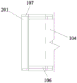
FIG. 2 is an enlarged schematic view of the rotatable wheel of FIG. 1;
FIG. 3 is an enlarged view of the rotating wheel of FIG. 2 in the direction of A-A;
FIG. 4 is a schematic view of the internal structure of the transmission case of FIG. 1;
FIG. 5 is a schematic view of the mounting plate of FIG. 1 taken in the direction B-B;
FIG. 6 is an enlarged schematic view of the mounting plate of FIG. 5 at C;
FIG. 7 is a schematic structural view of the roll-over panel of FIG. 6;
in the figure, a vertical column 101, an idler pulley 102, a connecting cavity 103, a conveying belt 104, a containing cavity 105, a rotating wheel 106, an upright rod 107, an open cavity 108, a box body 109, a mounting plate 110, a sliding cavity 112, a moving block 113, a transmission shaft 115, a hopper 116, a sliding box 117, a power motor 118, a power shaft 119, an inner connecting cavity 120, a connecting cavity 122, a rotating wheel 123, a flat plate 201, a transmission bevel gear 301, an engaging bevel gear 302, a power cavity 303, a shielding cavity 401, a sliding plate 402, a side rotating block 403, a turnover plate 404, an inner sliding cavity 405, a sliding push plate 406, an inner threaded block 407, a rotating motor 408, a rear side box 409, a guide rod 410, a penetrating cavity 411, a containing cavity 412, a guide cavity 501 and a round.
Detailed Description
As shown in fig. 1 to 7, the present invention is explained in detail, and for convenience of description, the following orientations are defined as follows: the following upper, lower, left, right, front and back directions are consistent with the upper, lower, left, right, front and back directions of the projection relation of the device in fig. 1, the device for treating a side slope of the present invention comprises a vertical column 101 fixed with an external mobile device through bolts, an installation plate 110 is fixedly arranged on the upper end surface of the vertical column 101, the installation plate 110 is of an L-shaped structure, a through cavity 105 is arranged in the installation plate 110, a sliding cavity 112 is arranged in the upper end wall of the cavity 105 in a communication manner, a connecting cavity 122 positioned in the installation plate 110 is arranged on the right side of the sliding cavity 112, the connecting cavity 122 is communicated with the cavity 105, an interconnecting cavity 120 is arranged in the upper end wall of the connecting cavity 122 in a communication manner, a connecting cavity 103 is arranged in the rear end wall of the cavity 105 in a communication manner, a storage device for storing seeds is arranged on the rear side of the connecting cavity 103, and, therefore, the device realizes the efficient sowing of the seeds.
Beneficially, the storage device comprises a hopper 116 fixed with the mounting plate 110, a containing cavity 412 for storing seeds is arranged in the hopper 116, the containing cavity 412 is arranged in a vertically penetrating manner, guide cavities 501 which are symmetrical left and right are arranged in front and rear end walls of the containing cavity 412 in a communicating manner, a flap assembly for controlling the seeds to fall is arranged between the mounting plate 110 and the hopper 116, and a driving assembly for driving the flap assembly to work is arranged at the rear side of the flap assembly, so that the seed release is realized by using the above assemblies.
Beneficially, the turning plate assembly comprises a side turning block 403 fixed to the rear end face of the mounting plate 110, a turning plate 404 is rotatably arranged in the side turning block 403, an open-ended inner sliding cavity 405 is arranged in the turning plate 404, a shielding structure for preventing seeds from falling is arranged in the turning plate 404, a round turning block 502 is rotatably arranged in the turning plate 404, the round turning block 502 is connected with the guide cavity 501 in a sliding fit manner, and the round turning block 502 is in power connection with the driving assembly through a connecting structure, so that seeds are accurately released and cannot fall.
Advantageously, the shielding structure comprises a protrusion fixed on the front end surface of the turning plate 404, and the protrusion forms an opening on the front end surface of the turning plate 404 to form a shielding cavity 401 for preventing the seeds from spilling, so that the seeds are prevented from spilling when falling by the structural configuration of the shielding cavity 401.
Advantageously, the connecting structure comprises a sliding push plate 406 fixed to the rear end surface of the circular rotating block 502, the sliding push plate 406 slidably penetrates through the rear end wall of the guide cavity 501 and penetrates out of the hopper 116, and the hopper 116 is of a flat plate structure, so that the seeds are lifted when the sliding push plate 406 is horizontal, and are driven to fall when the sliding push plate 406 is inclined.
Beneficially, the driving assembly includes a rear side box 409 fixedly disposed on a rear end surface of the hopper 116, a through cavity 411 penetrating up and down is disposed in the rear side box 409, a guide rod 410 is fixedly disposed between front and rear end walls of the through cavity 411, a rotating motor 408 is disposed on a rear end surface of the rear side box 409, an output shaft of the rotating motor 408 is connected with a front end wall of the through cavity 411 in a rotating fit manner, an internal thread block 407 slidably connected with the guide rod 410 is disposed on an outer surface of the output shaft of the rotating motor 408 in a threaded fit manner, and the sliding push plate 406 slidably extends into the through cavity 411 and is fixed to the internal thread block 407, so that the rotating motor 408 is used to drive the internal thread block 407 to move and then drive the sliding push plate 406 to slide.
Beneficially, the sowing device comprises a conveyer belt sowing assembly which is arranged in the accommodating cavity 105, the connecting cavity 122 and the interconnecting cavity 120 and adopts a conveyer belt to movably sow seeds, and a power assembly for driving the conveyer belt sowing assembly to work is arranged on the upper side of the conveyer belt sowing assembly, so that efficient seed sowing is realized by utilizing the above assemblies.
Beneficially, the belt seeding assembly includes a box body 109 connected with the accommodating cavity 105 in a sliding fit manner, an open cavity 108 is provided in the box body 109, a rotating wheel 106 is rotatably provided in the open cavity 108, a blocking structure for blocking seeds so that the seeds fall in order is provided on the outer side of the rotating wheel 106, an idle wheel 102 is rotatably provided on the right side of the accommodating cavity 105, a sliding box 117 is slidably provided in the inner connecting cavity 120, a motor-driven rotating wheel 123 is rotatably provided in the sliding box 117, a conveying belt 104 is provided on the outer surface of the rotating wheel 123 and the outer surface of the rotating wheel 106 in a power connection manner, the conveying belt 104 is bypassed by the lower side of the idle wheel 102, the conveying belt 104 is passed through the connecting cavity 122, and the conveying belt 104 is located on the lower side of the connecting cavity 103, so that the conveying belt 104 is used for driving.
Advantageously, the blocking structure comprises vertical rods 107 fixed in the open cavity 108 and located at the left and lower sides of the rotating wheel 106, and a plate 201 for blocking seeds is fixed between the vertical rods 107, so that the seeds are blocked by the plate 201.
Beneficially, the power assembly includes a power motor 118 fixedly arranged in the upper end wall of the inner connecting cavity 120, a power shaft 119 is arranged in the power motor 118 in a power connection manner, the power shaft 119 is in a screw-fit connection with the sliding box 117, a transmission shaft 115 is arranged between the left end wall and the right end wall of the sliding cavity 112 in a rotating manner, a moving block 113 in a sliding fit connection with the sliding cavity 112 is arranged on the outer surface of the transmission shaft 115 in a screw-fit connection manner, the moving block 113 extends into the containing cavity 105 and is fixed to the box body 109, a transmission box 121 fixed to the mounting plate 110 is arranged between the sliding cavity 112 and the inner connecting cavity 120, a power cavity 303 is arranged in the transmission box 121, the transmission shaft 115 rotatably extends into the power cavity 303, a transmission bevel gear 301 is fixedly arranged on the right end face of the transmission shaft 115, and an engagement bevel gear 302 is, the power shaft 119 rotatably extends into the power cavity 303 and is fixed with the meshing bevel gear 302, so that the power motor 118 is used for driving the sliding box 117 and the box body 109 to move through related structures in a power assembly, and seeds are sowed in a neat and uniform manner.
In the initial state, the above-mentioned devices, components and structures are in the inactive state, before the device is operated, the device is fixed to a mobile device in the external space, such as a vehicle, etc., the seeds are loaded in the accommodating cavity 412, the sliding plate 402 is in the vertical state, and the sliding plate 406 is in the horizontal state, so that the seeds are safely put into the accommodating cavity 412.
When the device works, firstly, seeds need to be sprinkled onto the upper side of the conveying belt 104 from the connecting cavity 103, the rotating motor 408 works to drive the inner thread block 407 to move backwards, so that the inner thread block 407 drives the sliding plate 406 to move backwards, the sliding plate 406 completely lifts the seeds and is limited in the accommodating cavity 412 because the sliding plate 406 is of a flat plate structure, the circular rotating block 502 drives the sliding plate 402 to swing in the process of moving backwards of the sliding plate 406, the seeds are guided and protected from being spilled because the shielding cavity 401 arranged in the sliding plate 402, and the sliding plate 402 is of a flat plate structure, the seeds enter the connecting cavity 103 along the sliding plate 406 and the sliding plate 402 and fall onto the conveying belt 104, and the conveying belt 104 is limited by the idler pulley 102, an inclined area is formed between the idle wheel 102 and the conveying belt 104 for loading seeds, the rotating wheel 123 drives the conveying belt 104 to move after starting to work, the conveying belt 104 moves on the outer surfaces of the conveying belt 104 and the rotating wheel 106, and then the seeds enter the upper side of the rotating wheel 106 along the conveying belt 104, due to the design of the flat plate 201 and the vertical rod 107, the seeds fall slowly and do not fall off, because the equipment is in an inclined state and is equal to the inclination angle of a side slope, the seeds are required to be neatly divided and operated according to a certain spreading density according to different positions and areas on the side slope, the power motor 118 drives the power shaft 119 to rotate, the meshing bevel gear 302 is driven to rotate after the power shaft 119 rotates, and the meshing bevel gear 302 drives the transmission bevel gear 301 to rotate after rotating, the transmission shaft 115 also rotates synchronously, at the moment, the screw pitches of the transmission shaft 115 and the power shaft 119 are designed according to a certain proportion, so that the moving block 113 and the sliding box 117 can synchronously run at the same running distance, the conveyer belt 104 keeps a state of constantly power connection, the moving block 113 drives the box body 109 to move after moving, seeds can fall onto a slope along the track of the box body 109, and due to the adoption of orderly-cutting seeding, the survival rate of the seeds is greatly improved, and the slope treatment effect is improved.
The above description is only an embodiment of the present invention, but the scope of the present invention is not limited thereto, and any changes or substitutions that are not thought of through the inventive work should be included in the scope of the present invention. Therefore, the protection scope of the present invention shall be subject to the protection scope defined by the claims.
Claims (6)
1. A side slope management device comprises a stand column fixed with an external mobile device through a bolt, wherein an installation plate is fixedly arranged on the upper end face of the stand column, the installation plate is of an L-shaped structure, a penetrating containing cavity is arranged in the installation plate, a sliding cavity is communicated and arranged in the upper end wall of the containing cavity, a connecting cavity located in the installation plate is arranged on the right side of the sliding cavity, the connecting cavity is communicated with the containing cavity, an inner connecting cavity is communicated and arranged in the upper end wall of the connecting cavity, a connecting cavity is communicated and arranged in the rear end wall of the containing cavity, a storage device used for storing seeds is arranged on the rear side of the connecting cavity, and a sowing device used for sowing the seeds is arranged in the containing cavity, the connecting cavity and the inner; the method is characterized in that: the sowing device comprises a conveying belt sowing assembly which is arranged in the containing cavity, the connecting cavity and the interconnecting cavity and adopts a conveying belt to movably sow seeds, and a power assembly for driving the conveying belt sowing assembly to work is arranged on the upper side of the conveying belt sowing assembly; the conveying belt seeding assembly comprises a box body in sliding fit connection with the containing cavity, an open cavity is formed in the box body, a rotating wheel is arranged in the open cavity in a rotating mode, a blocking structure used for blocking seeds to enable the seeds to fall in order is arranged on the outer side of the rotating wheel, an idle wheel is arranged on the right side of the containing cavity in a rotating mode, a sliding box is arranged in the inner connecting cavity in a sliding mode, a rotating wheel driven by a motor is arranged in the sliding box in a rotating mode, a conveying belt is arranged on the outer surface of the rotating wheel in a power connection mode, the conveying belt is wound around the lower side of the idle wheel and penetrates through the connecting cavity, and the conveying belt is located on the; the blocking structure comprises upright posts which are fixedly arranged in the opening cavity and positioned on the left side and the lower side of the rotating wheel, and a flat plate for blocking seeds is fixedly arranged between the upright posts; the power assembly comprises a power motor fixedly arranged in the upper end wall of the inner connection cavity, a power shaft is arranged in the power motor in a power connection mode, the power shaft is connected with the sliding box in a threaded fit mode, a transmission shaft is arranged between the left end wall and the right end wall of the sliding cavity in a rotating mode, a moving block connected with the sliding cavity in a sliding fit mode is arranged on the outer surface of the transmission shaft in a threaded fit mode, the moving block stretches into the containing cavity and is fixed with the box body, a transmission box fixed with the mounting plate is arranged between the sliding cavity and the inner connection cavity, a power cavity is arranged in the transmission box, the transmission shaft stretches into the power cavity in a rotating mode, a transmission bevel gear is fixedly arranged on the right end face of the transmission shaft, the upper side of the transmission bevel gear is meshed with the meshing bevel gear.
2. The slope treatment device according to claim 1, wherein: the storage device comprises a hopper fixed by a mounting plate, a containing cavity used for storing seeds is arranged in the hopper, the containing cavity is arranged in a penetrating manner from top to bottom, the front end wall and the rear end wall of the containing cavity are communicated with a guide cavity which is symmetrical left and right, a turning plate assembly used for controlling the seeds to fall is arranged between the mounting plate and the hopper, and a driving assembly used for driving the turning plate assembly to work is arranged on the rear side of the turning plate assembly.
3. The slope treatment device according to claim 2, wherein: the turnover plate assembly comprises a side turning block fixed on the rear end face of the mounting plate, a turnover plate is arranged in the side turning block in a rotating mode, an open-ended inner sliding cavity is formed in the turnover plate, a shielding structure for preventing seeds from falling is arranged in the turnover plate, a round turning block is arranged in the turnover plate in a rotating mode, the round turning block is connected with the guide cavity in a sliding fit mode, and the round turning block is connected with the driving assembly in a power mode through a connecting structure.
4. The slope treatment device according to claim 3, wherein: the shielding structure comprises a convex block fixedly arranged on the front end face of the turnover plate, and the convex block forms a shielding cavity with an opening used for preventing seeds from being scattered on the front end face of the turnover plate.
5. The slope treatment device according to claim 3, wherein: the connecting structure comprises a sliding push plate fixed with the rear end face of the round rotating block, the sliding push plate penetrates through the rear end wall of the guide cavity in a sliding mode and penetrates out of the hopper, and the hopper is of a flat plate type structure.
6. The slope treatment device according to claim 5, wherein: the drive assembly comprises a rear side box fixedly arranged on the rear end face of the hopper, a through cavity which penetrates through the hopper from top to bottom is arranged in the rear side box, a guide rod is fixedly arranged between the front end wall and the rear end wall of the through cavity, a rotating motor is arranged on the rear end face of the rear side box, an output shaft of the rotating motor is connected with the front end wall of the through cavity in a rotating fit mode, an internal thread block which is connected with the guide rod in a sliding fit mode is arranged on the outer surface of the output shaft of the rotating motor in a threaded fit mode, and a sliding push plate stretches into the through cavity and is.
Priority Applications (1)
| Application Number | Priority Date | Filing Date | Title |
|---|---|---|---|
| CN201910356222.XA CN110012705B (en) | 2019-04-29 | 2019-04-29 | Slope treatment device |
Applications Claiming Priority (1)
| Application Number | Priority Date | Filing Date | Title |
|---|---|---|---|
| CN201910356222.XA CN110012705B (en) | 2019-04-29 | 2019-04-29 | Slope treatment device |
Publications (2)
| Publication Number | Publication Date |
|---|---|
| CN110012705A CN110012705A (en) | 2019-07-16 |
| CN110012705B true CN110012705B (en) | 2020-11-10 |
Family
ID=67192867
Family Applications (1)
| Application Number | Title | Priority Date | Filing Date |
|---|---|---|---|
| CN201910356222.XA Active CN110012705B (en) | 2019-04-29 | 2019-04-29 | Slope treatment device |
Country Status (1)
| Country | Link |
|---|---|
| CN (1) | CN110012705B (en) |
Citations (7)
| Publication number | Priority date | Publication date | Assignee | Title |
|---|---|---|---|---|
| CN201957420U (en) * | 2011-03-04 | 2011-09-07 | 河南省农业科学院 | Automatic seeder |
| JP2011193829A (en) * | 2010-03-23 | 2011-10-06 | Hibara Seisakusho:Kk | Seed feeder |
| CN203136498U (en) * | 2013-04-14 | 2013-08-21 | 甘肃农业大学 | Performance test board for maize seed sowing device |
| CN204810911U (en) * | 2015-07-30 | 2015-12-02 | 谭志建 | Corn drill |
| US10058021B2 (en) * | 2011-02-18 | 2018-08-28 | Morris Industries Ltd. | Seeder with metering system having selectively powered metering sections |
| CN208317364U (en) * | 2018-04-18 | 2019-01-04 | 青海省收费公路管理处 | One kind being used for slope of highway grass-seed spreading gear |
| CN109463079A (en) * | 2018-11-23 | 2019-03-15 | 四川明峰农业开发有限公司 | A kind of vegetable cultivation seeding apparatus |
-
2019
- 2019-04-29 CN CN201910356222.XA patent/CN110012705B/en active Active
Patent Citations (7)
| Publication number | Priority date | Publication date | Assignee | Title |
|---|---|---|---|---|
| JP2011193829A (en) * | 2010-03-23 | 2011-10-06 | Hibara Seisakusho:Kk | Seed feeder |
| US10058021B2 (en) * | 2011-02-18 | 2018-08-28 | Morris Industries Ltd. | Seeder with metering system having selectively powered metering sections |
| CN201957420U (en) * | 2011-03-04 | 2011-09-07 | 河南省农业科学院 | Automatic seeder |
| CN203136498U (en) * | 2013-04-14 | 2013-08-21 | 甘肃农业大学 | Performance test board for maize seed sowing device |
| CN204810911U (en) * | 2015-07-30 | 2015-12-02 | 谭志建 | Corn drill |
| CN208317364U (en) * | 2018-04-18 | 2019-01-04 | 青海省收费公路管理处 | One kind being used for slope of highway grass-seed spreading gear |
| CN109463079A (en) * | 2018-11-23 | 2019-03-15 | 四川明峰农业开发有限公司 | A kind of vegetable cultivation seeding apparatus |
Also Published As
| Publication number | Publication date |
|---|---|
| CN110012705A (en) | 2019-07-16 |
Similar Documents
| Publication | Publication Date | Title |
|---|---|---|
| CN207321849U (en) | A kind of hand-held multifunctional seed drill | |
| CN112772048A (en) | Garden tree transplants and uses digging device | |
| CN110012705B (en) | Slope treatment device | |
| CN113661823A (en) | A high-efficient fruit tree fertilizer distributor for fruit tree is planted | |
| CN117016130A (en) | Quantitative fertilization shallow for vegetables | |
| CN114830857A (en) | Double-helix ridging and fertilizing device | |
| CN218649270U (en) | Agricultural planting device | |
| CN215935556U (en) | Gravel soil grape deep layer fertilizer distributor | |
| CN213880864U (en) | A complementary unit for forestry seedling culture | |
| CN212393185U (en) | Medicine-adding circulating soil environment improvement equipment | |
| CN116806508A (en) | Soil and fertilizer mixing hole fertilization device | |
| CN210298490U (en) | A seeder for farming | |
| CN213214330U (en) | Device is scattered to rich selenium humus nutrient fertilizer's of rich selenium fruit | |
| CN221151943U (en) | Fertilizing device for crop planting | |
| CN217905127U (en) | Fertilizer injection unit is used in strawberry planting | |
| CN119422850B (en) | Fertilizing equipment and topdressing method for planting bamboo shoots | |
| CN112369152A (en) | Saline and alkaline auxiliary device that administers of soil | |
| CN223528473U (en) | Multi-terrain self-propelled tree seed sowing device | |
| CN210444852U (en) | Solid fertilizer continuous sowing device for vegetable planting | |
| CN217183866U (en) | Fertilizer injection unit for vegetable planting | |
| CN219087797U (en) | Powdery fertilizer applying device | |
| CN216392376U (en) | Multifunctional film-laying seeder | |
| CN220140162U (en) | Corn fertilizer applicator | |
| CN222170414U (en) | A tomato seed uniform sowing device | |
| CN211240804U (en) | Green efficient topdressing device for wheat |
Legal Events
| Date | Code | Title | Description |
|---|---|---|---|
| PB01 | Publication | ||
| PB01 | Publication | ||
| SE01 | Entry into force of request for substantive examination | ||
| SE01 | Entry into force of request for substantive examination | ||
| TA01 | Transfer of patent application right | ||
| TA01 | Transfer of patent application right |
Effective date of registration: 20201021 Address after: 350200 B-2, 24th floor, Shiyang International City Office Building, Wuhang Street, Changle District, Fuzhou City, Fujian Province Applicant after: Fuzhou Siqi Technology Co.,Ltd. Address before: Room 401, 30-1 Pailing South Road, Qiandaohu Town, Chun'an County, Hangzhou City, Zhejiang Province Applicant before: Wang Fang |
|
| GR01 | Patent grant | ||
| GR01 | Patent grant |