CN110012574B - A hybrid control single-stage bridgeless Sepic and LLC LED driver circuit - Google Patents
A hybrid control single-stage bridgeless Sepic and LLC LED driver circuit Download PDFInfo
- Publication number
- CN110012574B CN110012574B CN201910321089.4A CN201910321089A CN110012574B CN 110012574 B CN110012574 B CN 110012574B CN 201910321089 A CN201910321089 A CN 201910321089A CN 110012574 B CN110012574 B CN 110012574B
- Authority
- CN
- China
- Prior art keywords
- power
- power diode
- diode
- switch tube
- capacitor
- Prior art date
- Legal status (The legal status is an assumption and is not a legal conclusion. Google has not performed a legal analysis and makes no representation as to the accuracy of the status listed.)
- Expired - Fee Related
Links
- 239000003990 capacitor Substances 0.000 claims abstract description 74
- 238000004804 winding Methods 0.000 claims abstract description 32
- 238000006243 chemical reaction Methods 0.000 claims abstract description 9
- 238000011084 recovery Methods 0.000 claims description 3
- 238000010586 diagram Methods 0.000 description 11
- 230000005284 excitation Effects 0.000 description 6
- 238000011217 control strategy Methods 0.000 description 3
- 238000005516 engineering process Methods 0.000 description 2
- 230000009286 beneficial effect Effects 0.000 description 1
- 230000033228 biological regulation Effects 0.000 description 1
- 230000000694 effects Effects 0.000 description 1
- 230000000087 stabilizing effect Effects 0.000 description 1
Images


Classifications
-
- H—ELECTRICITY
- H05—ELECTRIC TECHNIQUES NOT OTHERWISE PROVIDED FOR
- H05B—ELECTRIC HEATING; ELECTRIC LIGHT SOURCES NOT OTHERWISE PROVIDED FOR; CIRCUIT ARRANGEMENTS FOR ELECTRIC LIGHT SOURCES, IN GENERAL
- H05B45/00—Circuit arrangements for operating light-emitting diodes [LED]
Landscapes
- Circuit Arrangements For Discharge Lamps (AREA)
- Dc-Dc Converters (AREA)
Abstract
The invention relates to a mixed control single-stage bridgeless Sepic and LLC LED driveAn electrical circuit. Comprising a single-phase AC input source vinA first power diode D1A second power diode D2A third power diode D3A fourth power diode D4A fifth power diode D5Sixth power diode Ds1Seventh power diode Ds2A first power switch tube S1A second power switch tube S2The third power switch tube S3High frequency capacitor C1A first output capacitor CbusA second output capacitor CoResonant capacitor CrA first inductor L1A second inductor L2Resonant inductor LrThe high-frequency transformer T comprises a primary winding Np, a secondary winding Ns1 and a secondary winding Ns2, and an LED lamp load. The circuit can complete the scalable conversion, realize the wide input voltage range, the controllable bus voltage, the high power factor, the low conduction loss and the soft switching conversion, and improve the cost performance of the driving circuit.
Description
Technical Field
The invention relates to a hybrid control single-stage bridgeless Sepic and LLC LED drive circuit, which is used for realizing wide input voltage, controllable bus voltage, high power factor, high efficiency and soft switch conversion.
Background
The lighting electrical appliance needs to meet a series of related standards of mandatory network side input current low-frequency harmonic limitation, such as standards of IEEE519, IEC1000-3-2C and the like. Therefore, the power factor correction (powerfactor correction-PFC) technology becomes a key technology in the field of LED driving circuits, and research on high-efficiency PFC circuits becomes a hotspot.
The Sepic circuit is scalable and suitable for wide input voltage range, and the bridgeless SepicPFC circuit has inductance at the input end, so that the generated input and output current ripple and electromagnetic interference are small, the efficiency and power factor of the converter are improved, THD is reduced, and conduction loss is reduced.
The switching tube of the LLC resonant converter can work in a soft switching mode, the switching loss of the LLC resonant converter can be kept at a very low level, and the LLC resonant converter is widely applied to medium and high power LED driving systems. In general, the efficiency of an independent LLC resonant converter is above 90%. The traditional alternating current input LED driving power supply generally adopts a two-stage structure, wherein the front stage is a power factor correction circuit, and the rear stage is a DC-DC conversion circuit. The driving power supply with the two-stage structure needs to adopt two independent control systems respectively, so that the cost is high and the reliability is poor. In recent years, more and more students have started to pay attention to a single-stage LED driving power supply. The single-stage circuit multiplexes the switching tubes of the two-stage circuit to be integrated into one stage, reduces the number of the switching tubes, only needs one set of control system, improves the reliability, reduces the cost and has important engineering application value.
Disclosure of Invention
The invention aims to provide a hybrid control single-stage bridgeless Sepic and LLC LED drive circuit, which can regulate and control the DC bus voltage, realize wide input voltage range, high power factor, low conduction loss and soft switching conversion, and improve the cost performance of the drive circuit.
In order to achieve the purpose, the technical scheme of the invention is as follows: a mixed control single-stage bridgeless Sepic and LLC LED drive circuit comprises a single-phase AC input power supply vinA first power diode D1A second power diode D2A third power diode D3A fourth power diode D4A fifth power diode D5Sixth power diode Ds1Seventh power diode Ds2A first power switch tube S1A second power switch tube S2The third power switch tube S3High frequency capacitor C1A first output capacitor CbusA second output capacitor CoResonant capacitor CrA first inductor L1A second inductor L2Resonant inductor LrA high frequency transformer T, LED lamp load; the first power diode D1Cathode and first power switch tube S1Drain electrode, high frequency capacitor C1Is connected to one end of the second power diode D2Cathode and single-phase AC input power vinOne terminal of (1), a first power diode D1Is connected with the anode of the second powerPolar tube D2Anode of and the second power switch tube S2Source electrode, fifth power diode D5Anode of, second inductor L2One terminal of (1), a first output capacitor CbusNegative terminal of (1), resonant capacitor CrIs connected to said single-phase ac input power vinAnother end of (1) and the first inductor L1Is connected to one end of the first inductor L1And the other end of the first power switch tube S1Source electrode of the first power switch tube S2Drain electrode of (2), third power diode D3Is connected to the cathode of the second inductor L2And the other end of the first power diode and a fourth power diode D4Anode of (2), high-frequency capacitor C1Is connected to the other end of the first output capacitor CbusAnd a fourth power diode D4Cathode of the third power switch tube S3Is connected to the drain of the third power switch tube S3Source and third power diode D3Anode of (2), fifth power diode D5Cathode, resonant inductor LrIs connected to one end of the resonant inductor LrAnd the other end of the primary winding N of the high-frequency transformer TpThe same name end is connected with the resonant capacitor CrAnd the other end of the primary winding N of the high-frequency transformer TpThe synonyms are connected; the secondary winding N of the high-frequency transformer Ts1Different name terminal and secondary winding N of high-frequency transformer Ts2End of same name, second output capacitor CoIs connected with one end of the LED lamp load, and a secondary winding N of the high-frequency transformer Ts1Dotted terminal and sixth power diode Ds1Is connected with the anode of the secondary winding N of the high-frequency transformer Ts2The different name terminal and a seventh power diode Ds2Is connected to the anode of the sixth power diode Ds1Cathode of and seventh power diode Ds2Cathode of (2), second output capacitor CoThe positive terminal of the LED lamp and the other end of the LED lamp load are connected.
In an embodiment of the present invention, the first inductor L1A second inductor L2A first power diode D1A second power ofPolar tube D2A fourth power diode D4A first power switch tube S1A second power switch tube S2High frequency capacitor C1A first output capacitor CbusForming a bridge-free Sepic circuit; the second power switch tube S2The third power switch tube S3A third power diode D3A fifth power diode D5A second output capacitor CoResonant capacitor CrResonant inductor LrA high frequency transformer T and a sixth power diode Ds1Seventh power diode Ds2The LED lamp load forms an LLC circuit; the bridgeless Sepic circuit can work in a DCM mode, a BCM mode or a CCM mode, the LLC circuit works in a ZVS region, namely the LLC circuit works in fr1<fs<frRegion (f)r1Is the series-parallel resonant frequency, f, of the LLC circuitrThe series resonant frequency of the LLC circuit).
In an embodiment of the present invention, the first power diode D1A second power diode D2Being a rectifier diode, a third power diode D3A fourth power diode D4A fifth power diode D5Sixth power diode Ds1Seventh power diode Ds2Is a fast recovery diode.
In an embodiment of the invention, the first power switch tube S1A second power switch tube S2The third power switch tube S3The power MOSFET is a power MOSFET and adopts an APWM-PFM hybrid control mode, namely frequency conversion and duty ratio conversion control.
In an embodiment of the present invention, the resonant capacitor CrHigh frequency capacitor C1Is a high-frequency capacitor; the first output capacitor CbusA second output capacitor CoIs an electrolytic capacitor.
In an embodiment of the present invention, the resonant inductor LrIs the leakage inductance or the independent inductance of the high-frequency transformer T.
Compared with the prior art, the invention has the following beneficial effects:
1. the invention provides a mixed control single-stage bridgeless Sepic and LLC LED drive circuit, which only needs one set of control circuit, can improve the reliability of the circuit and reduce the cost and the conduction loss;
2. the Sepic circuit can be raised and lowered, and the applicable input voltage range is improved; the bridge-free Sepic circuit reduces conduction loss.
3. The APWM-PFM control can realize the regulation and control of the bus voltage and reduce the voltage stress of the switching tube.
Drawings
Fig. 1 is a schematic diagram of an LED driving circuit of a hybrid control single-stage bridgeless Sepic and LLC of the present invention.
Fig. 2 is a first equivalent circuit diagram of an operating stage of an LED driving circuit of a hybrid control single-stage bridgeless Sepic and LLC according to an embodiment of the present invention.
Fig. 3 is a second equivalent circuit diagram of the working stage of the LED driving circuit of the hybrid control single-stage bridgeless Sepic and LLC according to the embodiment of the present invention.
Fig. 4 is a third equivalent circuit diagram of the working stage of the LED driving circuit of the hybrid control single-stage bridgeless Sepic and LLC according to the embodiment of the present invention.
Fig. 5 is a fourth equivalent circuit diagram of the working stage of the LED driving circuit of the hybrid control single-stage bridgeless Sepic and LLC according to the embodiment of the present invention.
Fig. 6 is a fifth equivalent circuit diagram of the working stage of the LED driving circuit of the hybrid control single-stage bridgeless Sepic and LLC according to the embodiment of the present invention.
Fig. 7 is a sixth equivalent circuit diagram of an operating stage of an LED driving circuit of a hybrid control single-stage bridgeless Sepic and LLC according to an embodiment of the present invention.
Fig. 8 is a seventh equivalent circuit diagram of the working stage of the LED driving circuit of the hybrid control single-stage bridgeless Sepic and LLC according to the embodiment of the present invention.
Fig. 9 is an equivalent circuit diagram eight of the working stage of the LED driving circuit of the hybrid control single-stage bridgeless Sepic and LLC according to the embodiment of the present invention.
Fig. 10 is a logic block diagram of an APWM-PFM hybrid control strategy of an LED driving circuit of a hybrid control single-stage bridgeless Sepic and LLC according to an embodiment of the present invention.
Detailed Description
The technical scheme of the invention is specifically explained below with reference to the accompanying drawings.
As shown in fig. 1, the present embodiment provides a hybrid control single-stage bridgeless LED driving circuit for Sepic and LLC. Comprising a single-phase AC input source vinA first power diode D1A second power diode D2A third power diode D3A fourth power diode D4A fifth power diode D5Sixth power diode D6Seventh power diode D7Eighth power diode Ds1The ninth power diode Ds2A first power switch tube S1A second power switch tube S2High frequency capacitor C1A first output capacitor CbusA second output capacitor CoResonant capacitor CrA first inductor L1A second inductor L2Resonant inductor LrThe high-frequency transformer T comprises a primary winding Np, a secondary winding Ns1 and a secondary winding Ns2, and an LED lamp load.
The first power diode D1Cathode and first power switch tube S1Drain electrode, high frequency capacitor C1Is connected to one end of the second power diode D2Cathode and single-phase AC input power vinOne terminal of (1), a first power diode D1Is connected to the anode of the second power diode D2Anode of and the second power switch tube S2Source electrode, fifth power diode D5Anode of, second inductor L2One terminal of (1), a first output capacitor CbusNegative terminal of (1), resonant capacitor CrIs connected to said single-phase ac input power vinAnother end of (1) and the first inductor L1Is connected to one end of the first inductor L1And the other end of the first power switch tube S1Source electrode of the first power switch tube S2Drain electrode of (2), third power diode D3Is connected to the cathode of the second inductor L2And the other end of the first power diode and a fourth power diode D4Anode of (2), high-frequency capacitor C1Is connected to the other end of the first output terminal, the first output terminalContainer CbusAnd a fourth power diode D4Cathode of the third power switch tube S3Is connected to the drain of the third power switch tube S3Source and third power diode D3Anode of (2), fifth power diode D5Cathode, resonant inductor LrIs connected to one end of the resonant inductor LrAnd the other end of the primary winding N of the high-frequency transformer TpThe same name end is connected with the resonant capacitor CrAnd the other end of the primary winding N of the high-frequency transformer TpThe synonyms are connected; the secondary winding N of the high-frequency transformer Ts1Different name terminal and secondary winding N of high-frequency transformer Ts2End of same name, second output capacitor CoIs connected with one end of the LED lamp load, and a secondary winding N of the high-frequency transformer Ts1End of same name and sixth power diode Ds1Is connected with the anode of the secondary winding N of the high-frequency transformer Ts2The different name terminal and a seventh power diode Ds2Is connected to the anode of the sixth power diode Ds1Cathode of and seventh power diode Ds2Cathode of (2), second output capacitor CoThe positive terminal of the LED lamp and the other end of the LED lamp load are connected.
In this embodiment, the first inductor L1A second inductor L2A first power diode D1A second power diode D2A fourth power diode D4A first power switch tube S1A second power switch tube S2High frequency capacitor C1A first output capacitor CbusForming a bridge-free Sepic circuit; the second power switch tube S2The third power switch tube S3A third power diode D3A fifth power diode D5A second output capacitor CoResonant capacitor CrResonant inductor LrA high frequency transformer T and a sixth power diode Ds1Seventh power diode Ds2The LED lamp load forms an LLC circuit; the bridgeless Sepic circuit can work in DCM, BCM or CCM, the LLC circuit works in ZVS region, that is, the LLC circuit works infr1<fs<frRegion (f)r1Is the series-parallel resonant frequency, f, of the LLC circuitrThe series resonant frequency of the LLC circuit).
In this embodiment, the first power diode D1A second power diode D2Being a rectifier diode, a third power diode D3A fourth power diode D4A fifth power diode D5Sixth power diode Ds1Seventh power diode Ds2Is a fast recovery diode.
In this embodiment, the first power switch S1A second power switch tube S2The third power switch tube S3The power MOSFET is a power MOSFET and adopts an APWM-PFM hybrid control mode.
In this embodiment, the resonant capacitor CrHigh frequency capacitor C1Is a high-frequency capacitor; the first output capacitor CbusA second output capacitor CoIs an electrolytic capacitor.
In this embodiment, the resonant inductor LrIs the leakage inductance or the independent inductance of the high-frequency transformer T.
Specifically, as shown in fig. 2 to fig. 9, the present embodiment further provides a specific circuit operation mode of the LED driving circuit of the hybrid control single-stage bridgeless Sepic and LLC.
The Sepic circuit is designed to work in DCM mode, and the LLC circuit works in f moder1<fs<frRegion (f)r1Is the series-parallel resonant frequency, f, of the LLC circuitrThe series resonant frequency of the LLC circuit). In the positive and negative periods of the power frequency of the ac power supply, the working states of the circuit are symmetrical, here, the positive half period of the power frequency is taken as an example for explanation, the negative half period is not repeated, and fig. 2 to 9 are 8 modal equivalent diagrams of the positive half period.
Referring to fig. 2, a switching tube S1、S2Switching on and off tube S3Off, first inductor and second inductor current iL1、iL2And (4) increasing linearly. At this stage, the resonant inductor LrResonant capacitor CrAt resonant frequency Resonant current greater than exciting current, secondary diode Ds2(i.e., the seventh power diode D above)s2) And conducting. The voltage across the primary winding of the transformer is clamped at-nVoExcitation current with slope nVo/LmAnd (4) increasing linearly.
Referring to fig. 3, a switching tube S1、S2Is still on, the first inductor and the second inductor are current iL1、iL2Still rises linearly. At this time, the resonance current is equal to the excitation current, and at this time, the secondary diode Ds2Zero current is turned off. The primary winding of the transformer is no longer clamped by the output voltage, the resonant period is very large due to the very large excitation inductance, and the resonant current is kept consistent with the excitation current at this stage and is basically a constant value.
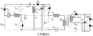
Referring to fig. 4, the switching tube S1、S2Off, first inductor and second inductor current iL1、iL2Linear decrease while LLC resonant frequency is A secondary diode D with resonant current greater than exciting currents1(i.e., the sixth power diode D above)s1) And conducting. The voltage across the primary winding of the transformer is clamped at nVoExcitation current with slope nVo/LmAnd (4) increasing linearly.
Referring to fig. 5, the switching tube S3On, first inductor and second inductor current iL1、iL2The linear decrease continues. Bus capacitor CbusIn a discharge state, while the LLC resonant frequency is A secondary diode D with resonant current greater than exciting currents1And conducting. The voltage across the primary winding of the transformer is clamped at nVoExcitation current with slope nVo/LmAnd (4) increasing linearly.
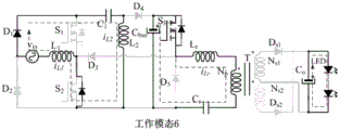
Referring to fig. 6, the switching tube S3Is still conducting. First inductor and second inductor current iL1、iL2The freewheeling ends. At this stage, the resonant inductor LrResonant capacitor CrAt resonant frequency Resonant current greater than exciting current, secondary diode Ds1And conducting. The voltage across the primary winding of the transformer is clamped at nVoExcitation current with slope nVo/LmAnd (4) increasing linearly.
Referring to fig. 7, the switching tube S3Is still conducting. At this time, the resonance current is equal to the excitation current, and at this time, the secondary diode Ds1Zero current is turned off. The primary winding of the transformer is no longer clamped by the output voltage, the resonant period is very large due to the very large excitation inductance, and the resonant current is kept consistent with the excitation current at this stage and is basically a constant value.
Referring to fig. 8, the switching tube S3Off, at this stage, diode D5Conducting, resonant inductance LrResonant capacitor CrAt resonant frequency Resonant current greater than exciting current, secondary diode Ds2And conducting. The voltage across the primary winding of the transformer is clamped at-nVoExcitation current with slope nVo/LmAnd (4) increasing linearly.
Referring to fig. 9, the switching tube S1、S2On, first inductor and second inductor current iL1、iL2Linearly rises, at this stage, diode D5Continuing to conduct, resonant inductor LrResonant capacitor CrAt resonant frequency Resonant current greater than exciting current, secondary diode Ds2And conducting. The voltage across the primary winding of the transformer is clamped at-nVoExcitation current with slope nVo/LmAnd (4) increasing linearly.
Referring to fig. 10, the APWM-PFM hybrid control strategy introduces a dc bus voltage proportional feedforward control in the conventional PFM control strategy, adjusts the duty ratio of the switching tube to control the dc bus voltage through the bus voltage proportional feedforward control, and adjusts the frequency f of the switching tube through the output current feedback controlsThereby stabilizing the output current.
The above are preferred embodiments of the present invention, and all changes made according to the technical scheme of the present invention that produce functional effects do not exceed the scope of the technical scheme of the present invention belong to the protection scope of the present invention.
Claims (6)
1. A mixed control single-stage bridgeless Sepic and LLC LED drive circuit is characterized by comprising a single-phase alternating current input power supply vinA first power diode D1A second power diode D2A third power diode D3A fourth power diode D4A fifth power diode D5Sixth power diode Ds1Seventh power diode Ds2A first power switch tube S1A second power switch tube S2The third power switch tube S3High frequency capacitor C1A first output capacitor CbusA second output capacitor CoResonant capacitor CrA first inductor L1A second inductor L2Resonant inductor LrA high frequency transformer T, LED lamp load; the first power diode D1Cathode and first power switch tube S1Drain electrode, high frequency capacitor C1Is connected to one end of the second power diode D2Cathode and single-phase AC input power vinOne terminal of (1), a first power diode D1Is connected to the anode of the second power diode D2Anode of and the second power switch tube S2Source electrode, fifth power diode D5Anode of, second inductor L2One terminal of (1), a first output capacitor CbusNegative terminal of (1), resonant capacitor CrIs connected to said single-phase ac input power vinAnother end of (1) and the first inductor L1Is connected to one end of the first inductor L1And the other end of the first power switch tube S1Source electrode of the first power switch tube S2Drain electrode of (2), third power diode D3Is connected to the cathode of the second inductor L2And the other end of the first power diode and a fourth power diode D4Anode of (2), high-frequency capacitor C1Is connected to the other end of the first output capacitor CbusAnd a fourth power diode D4Cathode of the third power switch tube S3Is connected to the drain of the third power switch tube S3Source and third power diode D3Anode of (2), fifth power diode D5Cathode, resonant inductor LrIs connected to one end of the resonant inductor LrAnd the other end of the primary winding N of the high-frequency transformer TpThe same name end is connected with the resonant capacitor CrAnd the other end of the primary winding N of the high-frequency transformer TpThe synonyms are connected; the secondary winding N of the high-frequency transformer Ts1Different name terminal and secondary winding N of high-frequency transformer Ts2End of same name, second output capacitor CoIs connected with one end of the LED lamp load, and a secondary winding N of the high-frequency transformer Ts1Dotted terminal and sixth power diode Ds1Is connected with the anode of the secondary winding N of the high-frequency transformer Ts2Different name terminal and seventh power diode Ds2Is connected to the anode of the sixth power diode Ds1Cathode of and seventh power diode Ds2Cathode of (2), second output capacitor CoThe positive terminal of the LED lamp and the other end of the LED lamp load are connected.
2. The LED driving circuit of Sepic and LLC of the hybrid control single stage of claim 1, wherein: the first inductor L1A second inductor L2A first power diode D1A second power diode D2A fourth power diode D4A first power switch tube S1A second power switch tube S2High frequency capacitor C1A first output capacitor CbusForming a bridge-free Sepic circuit; the second power switch tube S2The third power switch tube S3A third power diode D3A fifth power diode D5A second output capacitor CoResonant capacitor CrResonant inductor LrA high frequency transformer T and a sixth power diode Ds1Seventh power diode Ds2The LED lamp load forms an LLC circuit; the bridgeless Sepic circuit can work in a DCM mode, a BCM mode or a CCM mode, the LLC circuit works in a ZVS region, namely the LLC circuit works in fr1<fs<frRegion, fr1Is the series-parallel resonant frequency, f, of the LLC circuitrThe series resonant frequency of the LLC circuit.
3. The LED driving circuit of Sepic and LLC of the hybrid control single stage of claim 1, wherein: the first power diode D1A second power diode D2Being a rectifier diode, a third power diode D3A fourth power diode D4A fifth power diode D5Sixth power diode Ds1Seventh power diode Ds2Is a fast recovery diode.
4. The LED driving circuit of Sepic and LLC of the hybrid control single stage of claim 1, wherein: the first power switch tube S1A second power switch tube S2The third power switch tube S3The power MOSFET is a power MOSFET and adopts an APWM-PFM hybrid control mode, namely frequency conversion and duty ratio conversion control.
5. The LED driving circuit of Sepic and LLC of the hybrid control single stage of claim 1, wherein: the resonant capacitor CrHigh frequency capacitor C1Is a high-frequency capacitor; the first output capacitor CbusA second output capacitor CoIs an electrolytic capacitor.
6. According to claimClaim 1 said LED drive circuit of mixed control single-stage bridgeless Sepic and LLC characterized in that: the resonance inductor LrIs the leakage inductance or the independent inductance of the high-frequency transformer T.
Priority Applications (1)
| Application Number | Priority Date | Filing Date | Title |
|---|---|---|---|
| CN201910321089.4A CN110012574B (en) | 2019-04-19 | 2019-04-19 | A hybrid control single-stage bridgeless Sepic and LLC LED driver circuit |
Applications Claiming Priority (1)
| Application Number | Priority Date | Filing Date | Title |
|---|---|---|---|
| CN201910321089.4A CN110012574B (en) | 2019-04-19 | 2019-04-19 | A hybrid control single-stage bridgeless Sepic and LLC LED driver circuit |
Publications (2)
| Publication Number | Publication Date |
|---|---|
| CN110012574A CN110012574A (en) | 2019-07-12 |
| CN110012574B true CN110012574B (en) | 2021-06-01 |
Family
ID=67173390
Family Applications (1)
| Application Number | Title | Priority Date | Filing Date |
|---|---|---|---|
| CN201910321089.4A Expired - Fee Related CN110012574B (en) | 2019-04-19 | 2019-04-19 | A hybrid control single-stage bridgeless Sepic and LLC LED driver circuit |
Country Status (1)
| Country | Link |
|---|---|
| CN (1) | CN110012574B (en) |
Families Citing this family (4)
| Publication number | Priority date | Publication date | Assignee | Title |
|---|---|---|---|---|
| CN112953264A (en) * | 2021-03-18 | 2021-06-11 | 上海大学 | Bridgeless isolated switched capacitor SEPIC PFC converter |
| CN114286474B (en) * | 2021-12-30 | 2024-03-29 | 福州大学 | Bridgeless high-gain single-stage LED driving circuit and voltage-limiting current-limiting hybrid control method |
| CN118337067B (en) * | 2024-06-12 | 2024-08-06 | 国网浙江省电力有限公司金华供电公司 | A network-isolated LLC resonant conversion control system and method |
| CN121395930A (en) * | 2024-07-23 | 2026-01-23 | 厦门英聚恒电力电子研究有限公司 | Single-stage bridgeless conversion device integrating Buck-Boost and half-bridge LCC (inductance-capacitance) circuits |
Citations (5)
| Publication number | Priority date | Publication date | Assignee | Title |
|---|---|---|---|---|
| CN101707838A (en) * | 2009-12-04 | 2010-05-12 | 英飞特电子(杭州)有限公司 | Multipath LED constant current drive circuit suitable for non-isolated converter |
| CN107294407A (en) * | 2017-06-20 | 2017-10-24 | 南京航空航天大学 | A kind of AC DC transformation systems |
| CN108539981A (en) * | 2018-06-04 | 2018-09-14 | 南京矽力杰半导体技术有限公司 | DC-to-DC converter |
| CN108601146A (en) * | 2018-05-11 | 2018-09-28 | 福州大学 | A kind of high-power factor and output ripple and low Flyback/Sepic LED drive circuits |
| CN108684104A (en) * | 2018-05-23 | 2018-10-19 | 哈尔滨工业大学 | Based on the automotive LED headlamp driver for improving SEPIC Sofe Switch |
Family Cites Families (1)
| Publication number | Priority date | Publication date | Assignee | Title |
|---|---|---|---|---|
| DE102012007477B4 (en) * | 2012-04-13 | 2024-02-22 | Tridonic Gmbh & Co Kg | Method for operating an LLC resonant converter for a lamp, converter and LED converter |
-
2019
- 2019-04-19 CN CN201910321089.4A patent/CN110012574B/en not_active Expired - Fee Related
Patent Citations (5)
| Publication number | Priority date | Publication date | Assignee | Title |
|---|---|---|---|---|
| CN101707838A (en) * | 2009-12-04 | 2010-05-12 | 英飞特电子(杭州)有限公司 | Multipath LED constant current drive circuit suitable for non-isolated converter |
| CN107294407A (en) * | 2017-06-20 | 2017-10-24 | 南京航空航天大学 | A kind of AC DC transformation systems |
| CN108601146A (en) * | 2018-05-11 | 2018-09-28 | 福州大学 | A kind of high-power factor and output ripple and low Flyback/Sepic LED drive circuits |
| CN108684104A (en) * | 2018-05-23 | 2018-10-19 | 哈尔滨工业大学 | Based on the automotive LED headlamp driver for improving SEPIC Sofe Switch |
| CN108539981A (en) * | 2018-06-04 | 2018-09-14 | 南京矽力杰半导体技术有限公司 | DC-to-DC converter |
Also Published As
| Publication number | Publication date |
|---|---|
| CN110012574A (en) | 2019-07-12 |
Similar Documents
| Publication | Publication Date | Title |
|---|---|---|
| CN111049369B (en) | Hybrid control method for resonant converter in distributed power system | |
| CN108448913B (en) | A single-stage isolated AC-DC converter based on interleaved parallel bridgeless PFC circuit and LLC resonance | |
| Cheng et al. | Design and implementation of a high-power-factor LED driver with zero-voltage switching-on characteristics | |
| CN107222100B (en) | A single-stage LED driver circuit integrating Buck-Boost and LLC circuits | |
| CN111556616B (en) | A single-stage bridgeless boost Cuk resonant LED drive circuit | |
| Do | Soft-switching SEPIC converter with ripple-free input current | |
| CN107994789A (en) | A kind of isolated form integrated form AC-DC converter based on non-bridge PFC and LLC resonance | |
| CN108235509B (en) | A single-stage LED driver circuit integrating step-down Cuk and LLC circuits | |
| CN110012574B (en) | A hybrid control single-stage bridgeless Sepic and LLC LED driver circuit | |
| CN108601146B (en) | A single-stage high power factor and low output ripple Flyback/Sepic LED driver circuit | |
| CN103917017B (en) | A kind of single stage type no electrolytic capacitor AC/DC LED constant current drives power supply | |
| Chang et al. | An integrated high-power-factor converter with ZVS transition | |
| CN107041036A (en) | A kind of single-stage LED drive circuit of integrated bridgeless Boost and LLC circuits | |
| WO2025131138A1 (en) | Single-stage wide input soft switching resonant power supply conversion apparatus | |
| CN106100344A (en) | A kind of LLC resonant converter with liter high voltage gain | |
| CN113489309A (en) | Bridgeless buck power factor correction converter with wide output voltage and control method | |
| CN114665700B (en) | Forward and flyback-resonant type single-stage bridgeless isolated PFC converter | |
| CN112968621A (en) | Single-stage composite active clamping push-pull flyback inverter | |
| CN105554952A (en) | Interleaving LED drive circuit based on quadratic form Buck and working method thereof | |
| CN118842302A (en) | Single-stage conversion device integrating Buck-Boost and full-bridge LLC circuit | |
| CN118399756A (en) | Single-stage conversion device integrating Buck-Boost and AHB flyback circuit | |
| CN205123617U (en) | DCAC conversion equipment , DCDC conversion equipment and constant current drive device | |
| CN114640255A (en) | Series resonant converter and control method thereof | |
| CN102832802B (en) | PFC (power factor correction) circuit, communication power supply equipment and control method of PFC circuit | |
| CN105375807A (en) | Direct current (DC)/alternating current (AC) conversion device, direct current/ direct current conversion device and constant current driving device |
Legal Events
| Date | Code | Title | Description |
|---|---|---|---|
| PB01 | Publication | ||
| PB01 | Publication | ||
| SE01 | Entry into force of request for substantive examination | ||
| SE01 | Entry into force of request for substantive examination | ||
| GR01 | Patent grant | ||
| GR01 | Patent grant | ||
| CF01 | Termination of patent right due to non-payment of annual fee | ||
| CF01 | Termination of patent right due to non-payment of annual fee |
Granted publication date: 20210601 |