CN109965976B - Device for ablating tissue using ablation pulses - Google Patents
Device for ablating tissue using ablation pulses Download PDFInfo
- Publication number
- CN109965976B CN109965976B CN201910295542.9A CN201910295542A CN109965976B CN 109965976 B CN109965976 B CN 109965976B CN 201910295542 A CN201910295542 A CN 201910295542A CN 109965976 B CN109965976 B CN 109965976B
- Authority
- CN
- China
- Prior art keywords
- tissue
- probe
- fluid
- treatment
- carrier
- Prior art date
- Legal status (The legal status is an assumption and is not a legal conclusion. Google has not performed a legal analysis and makes no representation as to the accuracy of the status listed.)
- Active
Links
- 238000002679 ablation Methods 0.000 title claims description 139
- 239000012530 fluid Substances 0.000 claims abstract description 486
- 239000000523 sample Substances 0.000 claims description 450
- 238000011282 treatment Methods 0.000 claims description 356
- 238000002604 ultrasonography Methods 0.000 claims description 66
- XLYOFNOQVPJJNP-UHFFFAOYSA-N water Substances O XLYOFNOQVPJJNP-UHFFFAOYSA-N 0.000 claims description 53
- 230000002262 irrigation Effects 0.000 claims description 48
- 238000003973 irrigation Methods 0.000 claims description 48
- 230000033001 locomotion Effects 0.000 claims description 45
- 239000007788 liquid Substances 0.000 claims description 44
- 210000003708 urethra Anatomy 0.000 claims description 33
- 230000035515 penetration Effects 0.000 claims description 31
- 239000000463 material Substances 0.000 claims description 28
- FAPWRFPIFSIZLT-UHFFFAOYSA-M Sodium chloride Chemical compound [Na+].[Cl-] FAPWRFPIFSIZLT-UHFFFAOYSA-M 0.000 claims description 26
- 239000011780 sodium chloride Substances 0.000 claims description 25
- 230000008878 coupling Effects 0.000 claims description 24
- 238000010168 coupling process Methods 0.000 claims description 24
- 238000005859 coupling reaction Methods 0.000 claims description 24
- 230000002829 reductive effect Effects 0.000 claims description 15
- 230000004044 response Effects 0.000 claims description 15
- 230000007246 mechanism Effects 0.000 claims description 11
- 238000003032 molecular docking Methods 0.000 claims description 11
- 230000008021 deposition Effects 0.000 claims description 3
- 210000003608 fece Anatomy 0.000 claims description 3
- 210000001519 tissue Anatomy 0.000 description 448
- 210000002307 prostate Anatomy 0.000 description 102
- 238000000034 method Methods 0.000 description 86
- 239000013307 optical fiber Substances 0.000 description 72
- 238000003384 imaging method Methods 0.000 description 60
- 238000012545 processing Methods 0.000 description 49
- 210000000056 organ Anatomy 0.000 description 45
- 238000005520 cutting process Methods 0.000 description 44
- 210000003932 urinary bladder Anatomy 0.000 description 34
- 230000008569 process Effects 0.000 description 33
- 230000000762 glandular Effects 0.000 description 31
- 230000000875 corresponding effect Effects 0.000 description 29
- 238000002271 resection Methods 0.000 description 26
- 230000003287 optical effect Effects 0.000 description 25
- 230000008901 benefit Effects 0.000 description 22
- 238000012800 visualization Methods 0.000 description 17
- 230000006870 function Effects 0.000 description 16
- 239000003570 air Substances 0.000 description 15
- 238000004873 anchoring Methods 0.000 description 15
- 230000006378 damage Effects 0.000 description 15
- 238000005345 coagulation Methods 0.000 description 14
- 230000015271 coagulation Effects 0.000 description 14
- 238000013461 design Methods 0.000 description 14
- 210000004204 blood vessel Anatomy 0.000 description 13
- 230000003628 erosive effect Effects 0.000 description 13
- 206010004446 Benign prostatic hyperplasia Diseases 0.000 description 12
- 208000004403 Prostatic Hyperplasia Diseases 0.000 description 12
- 239000000969 carrier Substances 0.000 description 12
- 210000003484 anatomy Anatomy 0.000 description 11
- 239000003550 marker Substances 0.000 description 11
- 235000002595 Solanum tuberosum Nutrition 0.000 description 10
- 244000061456 Solanum tuberosum Species 0.000 description 10
- 230000015572 biosynthetic process Effects 0.000 description 10
- 238000012544 monitoring process Methods 0.000 description 10
- 238000001356 surgical procedure Methods 0.000 description 10
- 238000003780 insertion Methods 0.000 description 9
- 230000037431 insertion Effects 0.000 description 9
- 238000005259 measurement Methods 0.000 description 9
- 230000002792 vascular Effects 0.000 description 9
- 230000007423 decrease Effects 0.000 description 8
- 238000013507 mapping Methods 0.000 description 8
- 238000001228 spectrum Methods 0.000 description 8
- 239000002775 capsule Substances 0.000 description 7
- 238000004140 cleaning Methods 0.000 description 7
- 210000003734 kidney Anatomy 0.000 description 7
- 230000033228 biological regulation Effects 0.000 description 6
- 210000001072 colon Anatomy 0.000 description 6
- 239000004020 conductor Substances 0.000 description 6
- 238000012285 ultrasound imaging Methods 0.000 description 6
- 239000002699 waste material Substances 0.000 description 6
- 230000000740 bleeding effect Effects 0.000 description 5
- 238000004891 communication Methods 0.000 description 5
- 230000000694 effects Effects 0.000 description 5
- 238000002474 experimental method Methods 0.000 description 5
- 239000010437 gem Substances 0.000 description 5
- 229910001751 gemstone Inorganic materials 0.000 description 5
- 238000002347 injection Methods 0.000 description 5
- 239000007924 injection Substances 0.000 description 5
- 235000012015 potatoes Nutrition 0.000 description 5
- 238000010408 sweeping Methods 0.000 description 5
- 230000008467 tissue growth Effects 0.000 description 5
- CURLTUGMZLYLDI-UHFFFAOYSA-N Carbon dioxide Chemical compound O=C=O CURLTUGMZLYLDI-UHFFFAOYSA-N 0.000 description 4
- 230000005355 Hall effect Effects 0.000 description 4
- 239000012267 brine Substances 0.000 description 4
- 230000008859 change Effects 0.000 description 4
- 230000001186 cumulative effect Effects 0.000 description 4
- 210000001508 eye Anatomy 0.000 description 4
- 239000000835 fiber Substances 0.000 description 4
- 230000006872 improvement Effects 0.000 description 4
- 230000002401 inhibitory effect Effects 0.000 description 4
- 239000000203 mixture Substances 0.000 description 4
- 238000012986 modification Methods 0.000 description 4
- 230000004048 modification Effects 0.000 description 4
- 230000000149 penetrating effect Effects 0.000 description 4
- 230000002572 peristaltic effect Effects 0.000 description 4
- HPALAKNZSZLMCH-UHFFFAOYSA-M sodium;chloride;hydrate Chemical compound O.[Na+].[Cl-] HPALAKNZSZLMCH-UHFFFAOYSA-M 0.000 description 4
- 210000004872 soft tissue Anatomy 0.000 description 4
- 230000005540 biological transmission Effects 0.000 description 3
- 239000008280 blood Substances 0.000 description 3
- 210000004369 blood Anatomy 0.000 description 3
- 210000004027 cell Anatomy 0.000 description 3
- 210000004907 gland Anatomy 0.000 description 3
- 230000035876 healing Effects 0.000 description 3
- 238000010348 incorporation Methods 0.000 description 3
- 230000003993 interaction Effects 0.000 description 3
- 210000000936 intestine Anatomy 0.000 description 3
- 230000000670 limiting effect Effects 0.000 description 3
- 210000004072 lung Anatomy 0.000 description 3
- 210000003205 muscle Anatomy 0.000 description 3
- 230000011218 segmentation Effects 0.000 description 3
- 210000003491 skin Anatomy 0.000 description 3
- 239000007787 solid Substances 0.000 description 3
- 239000000126 substance Substances 0.000 description 3
- 230000008685 targeting Effects 0.000 description 3
- 238000001931 thermography Methods 0.000 description 3
- 238000012546 transfer Methods 0.000 description 3
- 206010028980 Neoplasm Diseases 0.000 description 2
- 210000000577 adipose tissue Anatomy 0.000 description 2
- 210000001367 artery Anatomy 0.000 description 2
- 210000000746 body region Anatomy 0.000 description 2
- 210000000988 bone and bone Anatomy 0.000 description 2
- 210000001185 bone marrow Anatomy 0.000 description 2
- 210000004556 brain Anatomy 0.000 description 2
- 201000011510 cancer Diseases 0.000 description 2
- 229910002092 carbon dioxide Inorganic materials 0.000 description 2
- 210000000845 cartilage Anatomy 0.000 description 2
- 238000005253 cladding Methods 0.000 description 2
- 230000001427 coherent effect Effects 0.000 description 2
- 238000007872 degassing Methods 0.000 description 2
- 230000004069 differentiation Effects 0.000 description 2
- 210000003238 esophagus Anatomy 0.000 description 2
- 238000011010 flushing procedure Methods 0.000 description 2
- 230000012010 growth Effects 0.000 description 2
- 210000002216 heart Anatomy 0.000 description 2
- 239000011810 insulating material Substances 0.000 description 2
- 230000000968 intestinal effect Effects 0.000 description 2
- 238000002608 intravascular ultrasound Methods 0.000 description 2
- 210000004185 liver Anatomy 0.000 description 2
- 210000004400 mucous membrane Anatomy 0.000 description 2
- 238000012634 optical imaging Methods 0.000 description 2
- 210000001672 ovary Anatomy 0.000 description 2
- 210000000496 pancreas Anatomy 0.000 description 2
- 230000036961 partial effect Effects 0.000 description 2
- 230000010412 perfusion Effects 0.000 description 2
- 210000003800 pharynx Anatomy 0.000 description 2
- 238000011471 prostatectomy Methods 0.000 description 2
- 210000000664 rectum Anatomy 0.000 description 2
- 230000009467 reduction Effects 0.000 description 2
- 210000005084 renal tissue Anatomy 0.000 description 2
- 210000001625 seminal vesicle Anatomy 0.000 description 2
- 210000005070 sphincter Anatomy 0.000 description 2
- 210000000278 spinal cord Anatomy 0.000 description 2
- 210000002784 stomach Anatomy 0.000 description 2
- 210000001550 testis Anatomy 0.000 description 2
- 238000013519 translation Methods 0.000 description 2
- 210000000626 ureter Anatomy 0.000 description 2
- 210000004291 uterus Anatomy 0.000 description 2
- 201000010653 vesiculitis Diseases 0.000 description 2
- 208000003200 Adenoma Diseases 0.000 description 1
- 206010001233 Adenoma benign Diseases 0.000 description 1
- 206010021639 Incontinence Diseases 0.000 description 1
- 206010060862 Prostate cancer Diseases 0.000 description 1
- 208000000236 Prostatic Neoplasms Diseases 0.000 description 1
- 238000009825 accumulation Methods 0.000 description 1
- 238000013459 approach Methods 0.000 description 1
- 238000000149 argon plasma sintering Methods 0.000 description 1
- 238000003491 array Methods 0.000 description 1
- 230000004888 barrier function Effects 0.000 description 1
- 238000005452 bending Methods 0.000 description 1
- 230000009286 beneficial effect Effects 0.000 description 1
- 238000001574 biopsy Methods 0.000 description 1
- 239000001569 carbon dioxide Substances 0.000 description 1
- 210000003850 cellular structure Anatomy 0.000 description 1
- 239000000919 ceramic Substances 0.000 description 1
- 238000006243 chemical reaction Methods 0.000 description 1
- 230000006835 compression Effects 0.000 description 1
- 238000007906 compression Methods 0.000 description 1
- 239000012141 concentrate Substances 0.000 description 1
- 238000012790 confirmation Methods 0.000 description 1
- 239000000470 constituent Substances 0.000 description 1
- 230000001276 controlling effect Effects 0.000 description 1
- 230000002596 correlated effect Effects 0.000 description 1
- 230000003247 decreasing effect Effects 0.000 description 1
- 230000001934 delay Effects 0.000 description 1
- 230000001419 dependent effect Effects 0.000 description 1
- 230000000994 depressogenic effect Effects 0.000 description 1
- 238000010586 diagram Methods 0.000 description 1
- 239000010432 diamond Substances 0.000 description 1
- 238000011038 discontinuous diafiltration by volume reduction Methods 0.000 description 1
- 201000010099 disease Diseases 0.000 description 1
- 208000037265 diseases, disorders, signs and symptoms Diseases 0.000 description 1
- 230000005489 elastic deformation Effects 0.000 description 1
- 229920001971 elastomer Polymers 0.000 description 1
- 239000000806 elastomer Substances 0.000 description 1
- 238000011846 endoscopic investigation Methods 0.000 description 1
- 230000001747 exhibiting effect Effects 0.000 description 1
- 238000001125 extrusion Methods 0.000 description 1
- 238000002839 fiber optic waveguide Methods 0.000 description 1
- 238000001914 filtration Methods 0.000 description 1
- 238000010304 firing Methods 0.000 description 1
- 238000000799 fluorescence microscopy Methods 0.000 description 1
- 238000002594 fluoroscopy Methods 0.000 description 1
- 230000005484 gravity Effects 0.000 description 1
- 210000004013 groin Anatomy 0.000 description 1
- 238000010438 heat treatment Methods 0.000 description 1
- 230000002706 hydrostatic effect Effects 0.000 description 1
- 238000005286 illumination Methods 0.000 description 1
- 238000007654 immersion Methods 0.000 description 1
- 201000001881 impotence Diseases 0.000 description 1
- 238000011065 in-situ storage Methods 0.000 description 1
- 230000010354 integration Effects 0.000 description 1
- 238000007915 intraurethral administration Methods 0.000 description 1
- 230000001788 irregular Effects 0.000 description 1
- 238000002504 lithotomy Methods 0.000 description 1
- 238000004519 manufacturing process Methods 0.000 description 1
- 239000011159 matrix material Substances 0.000 description 1
- 230000005055 memory storage Effects 0.000 description 1
- QSHDDOUJBYECFT-UHFFFAOYSA-N mercury Chemical compound [Hg] QSHDDOUJBYECFT-UHFFFAOYSA-N 0.000 description 1
- 229910052753 mercury Inorganic materials 0.000 description 1
- 229910052751 metal Inorganic materials 0.000 description 1
- 239000002184 metal Substances 0.000 description 1
- 210000001087 myotubule Anatomy 0.000 description 1
- 210000000944 nerve tissue Anatomy 0.000 description 1
- 230000001537 neural effect Effects 0.000 description 1
- 210000004977 neurovascular bundle Anatomy 0.000 description 1
- HLXZNVUGXRDIFK-UHFFFAOYSA-N nickel titanium Chemical compound [Ti].[Ti].[Ti].[Ti].[Ti].[Ti].[Ti].[Ti].[Ti].[Ti].[Ti].[Ni].[Ni].[Ni].[Ni].[Ni].[Ni].[Ni].[Ni].[Ni].[Ni].[Ni].[Ni].[Ni].[Ni] HLXZNVUGXRDIFK-UHFFFAOYSA-N 0.000 description 1
- 229910001000 nickel titanium Inorganic materials 0.000 description 1
- 239000002245 particle Substances 0.000 description 1
- 230000037361 pathway Effects 0.000 description 1
- 230000002093 peripheral effect Effects 0.000 description 1
- 238000003825 pressing Methods 0.000 description 1
- 230000001681 protective effect Effects 0.000 description 1
- 230000002685 pulmonary effect Effects 0.000 description 1
- 230000000541 pulsatile effect Effects 0.000 description 1
- 238000010926 purge Methods 0.000 description 1
- 238000011084 recovery Methods 0.000 description 1
- 230000001105 regulatory effect Effects 0.000 description 1
- 238000009877 rendering Methods 0.000 description 1
- 230000002441 reversible effect Effects 0.000 description 1
- 238000012552 review Methods 0.000 description 1
- 238000005070 sampling Methods 0.000 description 1
- 238000006748 scratching Methods 0.000 description 1
- 230000002393 scratching effect Effects 0.000 description 1
- 238000007789 sealing Methods 0.000 description 1
- 230000009528 severe injury Effects 0.000 description 1
- 238000007493 shaping process Methods 0.000 description 1
- 238000004088 simulation Methods 0.000 description 1
- 238000007711 solidification Methods 0.000 description 1
- 230000008023 solidification Effects 0.000 description 1
- 229910001220 stainless steel Inorganic materials 0.000 description 1
- 239000010935 stainless steel Substances 0.000 description 1
- 238000006467 substitution reaction Methods 0.000 description 1
- 230000000153 supplemental effect Effects 0.000 description 1
- 230000008961 swelling Effects 0.000 description 1
- 230000001360 synchronised effect Effects 0.000 description 1
- 238000012360 testing method Methods 0.000 description 1
- 238000002560 therapeutic procedure Methods 0.000 description 1
- 230000000451 tissue damage Effects 0.000 description 1
- 231100000827 tissue damage Toxicity 0.000 description 1
- 238000013334 tissue model Methods 0.000 description 1
- 238000012549 training Methods 0.000 description 1
- 230000001131 transforming effect Effects 0.000 description 1
- 238000011269 treatment regimen Methods 0.000 description 1
- 238000009834 vaporization Methods 0.000 description 1
- 230000008016 vaporization Effects 0.000 description 1
- 210000003462 vein Anatomy 0.000 description 1
- 230000000007 visual effect Effects 0.000 description 1
Images


Classifications
-
- A—HUMAN NECESSITIES
- A61—MEDICAL OR VETERINARY SCIENCE; HYGIENE
- A61B—DIAGNOSIS; SURGERY; IDENTIFICATION
- A61B17/00—Surgical instruments, devices or methods, e.g. tourniquets
- A61B17/32—Surgical cutting instruments
- A61B17/3203—Fluid jet cutting instruments
-
- A—HUMAN NECESSITIES
- A61—MEDICAL OR VETERINARY SCIENCE; HYGIENE
- A61B—DIAGNOSIS; SURGERY; IDENTIFICATION
- A61B18/00—Surgical instruments, devices or methods for transferring non-mechanical forms of energy to or from the body
- A61B18/04—Surgical instruments, devices or methods for transferring non-mechanical forms of energy to or from the body by heating
- A61B18/12—Surgical instruments, devices or methods for transferring non-mechanical forms of energy to or from the body by heating by passing a current through the tissue to be heated, e.g. high-frequency current
- A61B18/14—Probes or electrodes therefor
- A61B18/148—Probes or electrodes therefor having a short, rigid shaft for accessing the inner body transcutaneously, e.g. for neurosurgery or arthroscopy
-
- A—HUMAN NECESSITIES
- A61—MEDICAL OR VETERINARY SCIENCE; HYGIENE
- A61B—DIAGNOSIS; SURGERY; IDENTIFICATION
- A61B18/00—Surgical instruments, devices or methods for transferring non-mechanical forms of energy to or from the body
- A61B18/04—Surgical instruments, devices or methods for transferring non-mechanical forms of energy to or from the body by heating
- A61B18/12—Surgical instruments, devices or methods for transferring non-mechanical forms of energy to or from the body by heating by passing a current through the tissue to be heated, e.g. high-frequency current
- A61B18/14—Probes or electrodes therefor
- A61B18/1482—Probes or electrodes therefor having a long rigid shaft for accessing the inner body transcutaneously in minimal invasive surgery, e.g. laparoscopy
-
- A—HUMAN NECESSITIES
- A61—MEDICAL OR VETERINARY SCIENCE; HYGIENE
- A61B—DIAGNOSIS; SURGERY; IDENTIFICATION
- A61B18/00—Surgical instruments, devices or methods for transferring non-mechanical forms of energy to or from the body
- A61B18/04—Surgical instruments, devices or methods for transferring non-mechanical forms of energy to or from the body by heating
- A61B18/12—Surgical instruments, devices or methods for transferring non-mechanical forms of energy to or from the body by heating by passing a current through the tissue to be heated, e.g. high-frequency current
- A61B18/14—Probes or electrodes therefor
- A61B18/1485—Probes or electrodes therefor having a short rigid shaft for accessing the inner body through natural openings
-
- A—HUMAN NECESSITIES
- A61—MEDICAL OR VETERINARY SCIENCE; HYGIENE
- A61B—DIAGNOSIS; SURGERY; IDENTIFICATION
- A61B8/00—Diagnosis using ultrasonic, sonic or infrasonic waves
- A61B8/08—Detecting organic movements or changes, e.g. tumours, cysts, swellings
- A61B8/0833—Detecting organic movements or changes, e.g. tumours, cysts, swellings involving detecting or locating foreign bodies or organic structures
- A61B8/085—Detecting organic movements or changes, e.g. tumours, cysts, swellings involving detecting or locating foreign bodies or organic structures for locating body or organic structures, e.g. tumours, calculi, blood vessels, nodules
-
- A—HUMAN NECESSITIES
- A61—MEDICAL OR VETERINARY SCIENCE; HYGIENE
- A61B—DIAGNOSIS; SURGERY; IDENTIFICATION
- A61B8/00—Diagnosis using ultrasonic, sonic or infrasonic waves
- A61B8/12—Diagnosis using ultrasonic, sonic or infrasonic waves in body cavities or body tracts, e.g. by using catheters
-
- A—HUMAN NECESSITIES
- A61—MEDICAL OR VETERINARY SCIENCE; HYGIENE
- A61B—DIAGNOSIS; SURGERY; IDENTIFICATION
- A61B18/00—Surgical instruments, devices or methods for transferring non-mechanical forms of energy to or from the body
- A61B18/18—Surgical instruments, devices or methods for transferring non-mechanical forms of energy to or from the body by applying electromagnetic radiation, e.g. microwaves
- A61B18/20—Surgical instruments, devices or methods for transferring non-mechanical forms of energy to or from the body by applying electromagnetic radiation, e.g. microwaves using laser
- A61B18/22—Surgical instruments, devices or methods for transferring non-mechanical forms of energy to or from the body by applying electromagnetic radiation, e.g. microwaves using laser the beam being directed along or through a flexible conduit, e.g. an optical fibre; Couplings or hand-pieces therefor
- A61B18/24—Surgical instruments, devices or methods for transferring non-mechanical forms of energy to or from the body by applying electromagnetic radiation, e.g. microwaves using laser the beam being directed along or through a flexible conduit, e.g. an optical fibre; Couplings or hand-pieces therefor with a catheter
-
- A—HUMAN NECESSITIES
- A61—MEDICAL OR VETERINARY SCIENCE; HYGIENE
- A61B—DIAGNOSIS; SURGERY; IDENTIFICATION
- A61B17/00—Surgical instruments, devices or methods, e.g. tourniquets
- A61B17/00234—Surgical instruments, devices or methods, e.g. tourniquets for minimally invasive surgery
- A61B2017/00238—Type of minimally invasive operation
- A61B2017/00274—Prostate operation, e.g. prostatectomy, turp, bhp treatment
-
- A—HUMAN NECESSITIES
- A61—MEDICAL OR VETERINARY SCIENCE; HYGIENE
- A61B—DIAGNOSIS; SURGERY; IDENTIFICATION
- A61B17/00—Surgical instruments, devices or methods, e.g. tourniquets
- A61B17/32—Surgical cutting instruments
- A61B17/3203—Fluid jet cutting instruments
- A61B2017/32032—Fluid jet cutting instruments using cavitation of the fluid
-
- A—HUMAN NECESSITIES
- A61—MEDICAL OR VETERINARY SCIENCE; HYGIENE
- A61B—DIAGNOSIS; SURGERY; IDENTIFICATION
- A61B18/00—Surgical instruments, devices or methods for transferring non-mechanical forms of energy to or from the body
- A61B2018/00053—Mechanical features of the instrument of device
- A61B2018/00166—Multiple lumina
-
- A—HUMAN NECESSITIES
- A61—MEDICAL OR VETERINARY SCIENCE; HYGIENE
- A61B—DIAGNOSIS; SURGERY; IDENTIFICATION
- A61B18/00—Surgical instruments, devices or methods for transferring non-mechanical forms of energy to or from the body
- A61B2018/00053—Mechanical features of the instrument of device
- A61B2018/00273—Anchoring means for temporary attachment of a device to tissue
- A61B2018/00279—Anchoring means for temporary attachment of a device to tissue deployable
- A61B2018/00285—Balloons
-
- A—HUMAN NECESSITIES
- A61—MEDICAL OR VETERINARY SCIENCE; HYGIENE
- A61B—DIAGNOSIS; SURGERY; IDENTIFICATION
- A61B18/00—Surgical instruments, devices or methods for transferring non-mechanical forms of energy to or from the body
- A61B2018/00315—Surgical instruments, devices or methods for transferring non-mechanical forms of energy to or from the body for treatment of particular body parts
- A61B2018/00505—Urinary tract
- A61B2018/00517—Urinary bladder or urethra
-
- A—HUMAN NECESSITIES
- A61—MEDICAL OR VETERINARY SCIENCE; HYGIENE
- A61B—DIAGNOSIS; SURGERY; IDENTIFICATION
- A61B18/00—Surgical instruments, devices or methods for transferring non-mechanical forms of energy to or from the body
- A61B2018/00315—Surgical instruments, devices or methods for transferring non-mechanical forms of energy to or from the body for treatment of particular body parts
- A61B2018/00547—Prostate
-
- A—HUMAN NECESSITIES
- A61—MEDICAL OR VETERINARY SCIENCE; HYGIENE
- A61B—DIAGNOSIS; SURGERY; IDENTIFICATION
- A61B18/00—Surgical instruments, devices or methods for transferring non-mechanical forms of energy to or from the body
- A61B2018/00571—Surgical instruments, devices or methods for transferring non-mechanical forms of energy to or from the body for achieving a particular surgical effect
- A61B2018/00589—Coagulation
-
- A—HUMAN NECESSITIES
- A61—MEDICAL OR VETERINARY SCIENCE; HYGIENE
- A61B—DIAGNOSIS; SURGERY; IDENTIFICATION
- A61B18/00—Surgical instruments, devices or methods for transferring non-mechanical forms of energy to or from the body
- A61B2018/00636—Sensing and controlling the application of energy
-
- A—HUMAN NECESSITIES
- A61—MEDICAL OR VETERINARY SCIENCE; HYGIENE
- A61B—DIAGNOSIS; SURGERY; IDENTIFICATION
- A61B18/00—Surgical instruments, devices or methods for transferring non-mechanical forms of energy to or from the body
- A61B2018/0091—Handpieces of the surgical instrument or device
- A61B2018/00916—Handpieces of the surgical instrument or device with means for switching or controlling the main function of the instrument or device
-
- A—HUMAN NECESSITIES
- A61—MEDICAL OR VETERINARY SCIENCE; HYGIENE
- A61B—DIAGNOSIS; SURGERY; IDENTIFICATION
- A61B18/00—Surgical instruments, devices or methods for transferring non-mechanical forms of energy to or from the body
- A61B2018/00982—Surgical instruments, devices or methods for transferring non-mechanical forms of energy to or from the body combined with or comprising means for visual or photographic inspections inside the body, e.g. endoscopes
-
- A—HUMAN NECESSITIES
- A61—MEDICAL OR VETERINARY SCIENCE; HYGIENE
- A61B—DIAGNOSIS; SURGERY; IDENTIFICATION
- A61B18/00—Surgical instruments, devices or methods for transferring non-mechanical forms of energy to or from the body
- A61B2018/00994—Surgical instruments, devices or methods for transferring non-mechanical forms of energy to or from the body combining two or more different kinds of non-mechanical energy or combining one or more non-mechanical energies with ultrasound
-
- A—HUMAN NECESSITIES
- A61—MEDICAL OR VETERINARY SCIENCE; HYGIENE
- A61B—DIAGNOSIS; SURGERY; IDENTIFICATION
- A61B18/00—Surgical instruments, devices or methods for transferring non-mechanical forms of energy to or from the body
- A61B18/04—Surgical instruments, devices or methods for transferring non-mechanical forms of energy to or from the body by heating
- A61B18/12—Surgical instruments, devices or methods for transferring non-mechanical forms of energy to or from the body by heating by passing a current through the tissue to be heated, e.g. high-frequency current
- A61B18/14—Probes or electrodes therefor
- A61B2018/1405—Electrodes having a specific shape
- A61B2018/1407—Loop
- A61B2018/141—Snare
-
- A—HUMAN NECESSITIES
- A61—MEDICAL OR VETERINARY SCIENCE; HYGIENE
- A61B—DIAGNOSIS; SURGERY; IDENTIFICATION
- A61B18/00—Surgical instruments, devices or methods for transferring non-mechanical forms of energy to or from the body
- A61B18/04—Surgical instruments, devices or methods for transferring non-mechanical forms of energy to or from the body by heating
- A61B18/12—Surgical instruments, devices or methods for transferring non-mechanical forms of energy to or from the body by heating by passing a current through the tissue to be heated, e.g. high-frequency current
- A61B18/14—Probes or electrodes therefor
- A61B2018/1405—Electrodes having a specific shape
- A61B2018/144—Wire
-
- A—HUMAN NECESSITIES
- A61—MEDICAL OR VETERINARY SCIENCE; HYGIENE
- A61B—DIAGNOSIS; SURGERY; IDENTIFICATION
- A61B18/00—Surgical instruments, devices or methods for transferring non-mechanical forms of energy to or from the body
- A61B18/18—Surgical instruments, devices or methods for transferring non-mechanical forms of energy to or from the body by applying electromagnetic radiation, e.g. microwaves
- A61B18/20—Surgical instruments, devices or methods for transferring non-mechanical forms of energy to or from the body by applying electromagnetic radiation, e.g. microwaves using laser
- A61B18/22—Surgical instruments, devices or methods for transferring non-mechanical forms of energy to or from the body by applying electromagnetic radiation, e.g. microwaves using laser the beam being directed along or through a flexible conduit, e.g. an optical fibre; Couplings or hand-pieces therefor
- A61B2018/2255—Optical elements at the distal end of probe tips
- A61B2018/2272—Optical elements at the distal end of probe tips with reflective or refractive surfaces for deflecting the beam
-
- A—HUMAN NECESSITIES
- A61—MEDICAL OR VETERINARY SCIENCE; HYGIENE
- A61B—DIAGNOSIS; SURGERY; IDENTIFICATION
- A61B18/00—Surgical instruments, devices or methods for transferring non-mechanical forms of energy to or from the body
- A61B18/18—Surgical instruments, devices or methods for transferring non-mechanical forms of energy to or from the body by applying electromagnetic radiation, e.g. microwaves
- A61B18/20—Surgical instruments, devices or methods for transferring non-mechanical forms of energy to or from the body by applying electromagnetic radiation, e.g. microwaves using laser
- A61B18/22—Surgical instruments, devices or methods for transferring non-mechanical forms of energy to or from the body by applying electromagnetic radiation, e.g. microwaves using laser the beam being directed along or through a flexible conduit, e.g. an optical fibre; Couplings or hand-pieces therefor
- A61B2018/2255—Optical elements at the distal end of probe tips
- A61B2018/2288—Optical elements at the distal end of probe tips the optical fibre cable having a curved distal end
-
- A—HUMAN NECESSITIES
- A61—MEDICAL OR VETERINARY SCIENCE; HYGIENE
- A61B—DIAGNOSIS; SURGERY; IDENTIFICATION
- A61B34/00—Computer-aided surgery; Manipulators or robots specially adapted for use in surgery
- A61B34/25—User interfaces for surgical systems
- A61B2034/254—User interfaces for surgical systems being adapted depending on the stage of the surgical procedure
-
- A—HUMAN NECESSITIES
- A61—MEDICAL OR VETERINARY SCIENCE; HYGIENE
- A61B—DIAGNOSIS; SURGERY; IDENTIFICATION
- A61B90/00—Instruments, implements or accessories specially adapted for surgery or diagnosis and not covered by any of the groups A61B1/00 - A61B50/00, e.g. for luxation treatment or for protecting wound edges
- A61B90/36—Image-producing devices or illumination devices not otherwise provided for
- A61B90/37—Surgical systems with images on a monitor during operation
- A61B2090/378—Surgical systems with images on a monitor during operation using ultrasound
-
- A—HUMAN NECESSITIES
- A61—MEDICAL OR VETERINARY SCIENCE; HYGIENE
- A61B—DIAGNOSIS; SURGERY; IDENTIFICATION
- A61B2217/00—General characteristics of surgical instruments
- A61B2217/002—Auxiliary appliance
- A61B2217/005—Auxiliary appliance with suction drainage system
-
- A—HUMAN NECESSITIES
- A61—MEDICAL OR VETERINARY SCIENCE; HYGIENE
- A61B—DIAGNOSIS; SURGERY; IDENTIFICATION
- A61B2217/00—General characteristics of surgical instruments
- A61B2217/002—Auxiliary appliance
- A61B2217/007—Auxiliary appliance with irrigation system
-
- A—HUMAN NECESSITIES
- A61—MEDICAL OR VETERINARY SCIENCE; HYGIENE
- A61B—DIAGNOSIS; SURGERY; IDENTIFICATION
- A61B2218/00—Details of surgical instruments, devices or methods for transferring non-mechanical forms of energy to or from the body
- A61B2218/001—Details of surgical instruments, devices or methods for transferring non-mechanical forms of energy to or from the body having means for irrigation and/or aspiration of substances to and/or from the surgical site
- A61B2218/002—Irrigation
-
- A—HUMAN NECESSITIES
- A61—MEDICAL OR VETERINARY SCIENCE; HYGIENE
- A61B—DIAGNOSIS; SURGERY; IDENTIFICATION
- A61B2218/00—Details of surgical instruments, devices or methods for transferring non-mechanical forms of energy to or from the body
- A61B2218/001—Details of surgical instruments, devices or methods for transferring non-mechanical forms of energy to or from the body having means for irrigation and/or aspiration of substances to and/or from the surgical site
- A61B2218/007—Aspiration
-
- A—HUMAN NECESSITIES
- A61—MEDICAL OR VETERINARY SCIENCE; HYGIENE
- A61B—DIAGNOSIS; SURGERY; IDENTIFICATION
- A61B90/00—Instruments, implements or accessories specially adapted for surgery or diagnosis and not covered by any of the groups A61B1/00 - A61B50/00, e.g. for luxation treatment or for protecting wound edges
- A61B90/36—Image-producing devices or illumination devices not otherwise provided for
Abstract
The present application relates to devices for ablating tissue using shedding pulses that direct a flow of fluid toward the tissue to generate a plurality of shedding clouds. The fluid flow may be scanned such that the plurality of shedding clouds arrive at different overlapping locations. Each of the plurality of shedding clouds may remove a portion of the tissue. In many embodiments, a device for ablating tissue includes a source of pressurized fluid and a nozzle coupled to the source of pressurized fluid to release a flow of fluid, wherein the flow of fluid generates a plurality of shedding clouds.
Description
The present application is a divisional application of the application entitled "device for ablating tissue with delinquent pulses" (formerly "automated image-guided tissue ablation and treatment"), filed as 2014, 9, 5, and application number 201480061035.4.
Cross-referencing
This PCT application requires us provisional patent application serial No. 62/019,305 entitled "AUTOMATED IMAGE-GUIDED time reset AND TREATMENT," filed 30/6 2014; U.S. provisional patent application Ser. No. 61/972,730 entitled "AUTOMATED IMAGE-GUIDED time reset AND TREATMENT", filed 3/31/2014; priority of U.S. provisional patent application serial No. 61/874,849 entitled "AUTOMATED IMAGE-GUIDED time reset AND TREATMENT", filed on 6.9.2013; the entire disclosure of the above application is incorporated herein by reference.
The subject matter of the present application relates to PCT application number PCT/US2013/028441, entitled "AUTOMATED IMAGE-GUIDED time reset AND TREATMENT", filed 28/2/2013; and U.S. patent application Ser. No. 61/604,932, entitled "AUTOMATED IMAGE-GUIDED INTRA-ORGAN RESONATION AND TREATMENT", filed 29/2/2012; 12/399,585 entitled "TISSUE ABLATION AND CAUTERIY WITH OPTICAL ENERGY CARRIED IN FLUID STREAM" published in US 20090227998, AND filed on 3, 6, 2009; application serial number 12/700,568 entitled "MULTI flip flop communication method AND DEVICES" filed on 4.2.2010, published as US 20110184391; and 7,882,841 entitled "MINIMALLY INVASIVE METHODS AND DEVICES FOR THE TREATMENT OF state diseas" entitled 2/8/2011; PCT application number PCT/US2011/023781 entitled "MULTI flute TISSUE reset METHODS AND DEVICES" filed on 8.4.2007, 8.11.2011, and published in WO2011097505, the entire disclosure of which is incorporated herein by reference.
Background
The field of the invention relates to treating tissue with energy, and more particularly to treating an organ such as the prostate with fluid flow energy.
Existing methods and devices for treating a subject, such as a patient, may result in less than ideal removal in at least some instances. For example, existing prostate surgical procedures may, in at least some instances, result in longer healing times and less than desirable results.
Existing methods and apparatus for imaging tissue may not be ideal for imaging the tissue being treated. For example, existing ultrasound methods and apparatus may not be well suited for viewing the treatment field of view during treatment, and the alignment of the diagnostic images with the treatment images may not be ideal. In addition, at least some existing treatment methods and devices for treating tissue may not be well suited for incorporation with prior art imaging systems. In at least some instances, it would be helpful to provide improved imaging of tissue during surgery, for example, to provide real-time imaging of tissue to allow a user to adjust the treatment based on the real-time image of the tissue. At least some existing methods and devices for imaging tissue during surgery may be somewhat awkward to use and may result in delays in patient handling.
Existing methods and devices to treat organs such as the prostate may provide a user interface that is somewhat inconvenient to the user and may provide less than ideal surgical planning. In addition, at least some existing methods and devices for treating tissue, such as prostate tissue, may be less accurate than ideal. In at least some instances, existing methods and devices may provide a less than ideal user experience. In addition, at least some existing interfaces may provide less than ideal coupling of the treatment device to the tissue structure.
Improved methods for tissue resection are described in U.S. patent No. 7,882,841 and pending applications U.S.12/700,568 and U.S.12/399,585. The methods and systems described in the above patents and patent applications rely on the positioning of a probe, such as a urethral probe, that directs fluid flow radially outward for controlled ablation of tissue, such as prostate tissue and luminal tissue. Optionally, the fluid flow may be used to deliver a light, electrical, thermal or other energy source to assist in ablating and/or cauterizing the treated tissue.
Work in relation to the embodiments has shown that treatment of diseased tissue may be less than ideal in at least some instances. For example, diseased tissue may not provide fluid flow similar to healthy tissue, and work related to embodiments suggests that diseased tissue may involve swelling and stretching with minor changes in fluid delivery and removal. Thus, despite improvements over the prior art, recovery and healing may take somewhat longer than ideal in at least some instances.
Furthermore, it would be helpful to have an improved monitoring of a surgical procedure that can be easily implemented in a low cost manner, enabling many people to benefit from advances in the field of surgical robotics. In at least some instances, it would be helpful to have improved imaging of a surgical site. In addition, it would be helpful to determine when a treatment may be outside of a boundary such as the prostate capsule, for example, and to provide a measurement device with the treatment apparatus to inhibit cutting too deep and perforating tissue such as the prostate capsule. While ultrasound imaging may be helpful, it would be desirable to have improved alignment between the ultrasound probe and the treatment probe.
While these methods are very effective and represent a significant advance over existing luminal tissue processing protocols, it is desirable to provide improvements to facilitate more accurate tissue removal in both fully automated and physician-assisted modes of operation.
Disclosure of Invention
At least some of these objectives will be met by the invention described hereinafter.
Embodiments of the present invention provide improved methods and apparatus for performing tissue ablation, such as prostate tissue ablation, by positioning an energy source within the urethra.
Embodiments of the present invention provide improved methods and apparatus for performing tissue ablation, such as prostate tissue ablation, by positioning an energy source within the urethra. In many embodiments, a fluid flow is directed toward tissue to generate a plurality of degassing masses. The fluid flow may be scanned such that the plurality of shedding clouds arrive at different overlapping locations. Each of the plurality of shedding clouds may remove a portion of the tissue. In many embodiments, a device for ablating tissue includes a source of pressurized fluid and a nozzle coupled to the source of pressurized fluid to release a flow of fluid, wherein the flow of fluid generates a plurality of shedding clouds.
In a first aspect, embodiments provide 1) a method of ablating tissue. A fluid flow is directed toward the tissue to generate a plurality of degassing masses. Scanning the fluid stream such that the plurality of shedding clouds arrive at different overlapping locations.
2) In many embodiments, each of the plurality of shedding clouds removes a portion of the tissue according to the method of item 1).
3) In many embodiments, the shedding clouds comprise cavitation visible to the user according to the method of item 1).
4) In many embodiments, the method of item 1), the fluid stream comprises a first liquid released into a second liquid to generate the shedding clouds.
5) In many embodiments, the method of item 4), the first liquid comprises saline and the second liquid comprises saline.
6) In many embodiments, the fluid flow is scanned with one or more of a hand-held probe or a probe coupled to a linkage according to the method of item 1).
In another aspect, embodiments provide 7) a device for ablating tissue. The apparatus includes a source of pressurized fluid and a nozzle coupled to the source of pressurized fluid to release a flow of fluid. The fluid flow generates a plurality of shedding clouds, wherein each of the plurality of shedding clouds removes a portion of the tissue.
8) In many embodiments, the apparatus of item 7), further comprising a scanner coupled to the nozzle, the scanner ablating each portion of the tissue using partially overlapping shedding clouds.
9) In many embodiments, the device of item 7), the fluid stream comprising a liquid, the device further comprising an irrigation opening for irrigating the tissue with a second liquid.
10) In many embodiments, the device of item 7), the first liquid comprises saline, and the second liquid comprises saline.
11) In many embodiments, the apparatus of item 7), the nozzle comprises a Strouhal number in the range of about 0.02 to about 0.03.
12) In many embodiments, the device of clause 7), the fluid source comprises a pump having a frequency less than a shedding pulse frequency.
13) In many embodiments, the apparatus of clause 7), the shedding pulses comprise a frequency ranging from about 1kHz to about 10 kHz.
The present application further provides the following:
14) an apparatus for treating tissue of a patient, comprising: a stiff sheath having a proximal end and a distal end; and a probe comprising an ablation energy source and at least one opening distal to the ablation energy source, the probe sized to fit within the sheath such that the at least one opening and the ablation energy source can be advanced beyond a distal end of the sheath, wherein a suction channel extends proximally from the at least one opening to a coupled suction source to remove fluid from a surgical procedure through the at least one opening.
15) The apparatus of item 14), further comprising a pump coupled to the at least one opening to remove material through the at least one opening at a predetermined rate.
16) The apparatus of item 15), further comprising a pump and a pressure sensor coupled to the aspiration channel and the pump, and wherein the pump removes material at a variable rate in response to the pressure sensor so as to maintain a constant pressure in the channel.
17) The device of item 15), wherein the rate comprises an amount greater than a liquid flow rate through a nozzle of the ablation energy source.
18) The device of item 14), further comprising an opening for coupling to a source of irrigation fluid to provide irrigation of the surgical site.
19) The device of clause 18), wherein an opening for coupling to the irrigation fluid source and an endoscopic viewing window are located proximal to the ablation energy source so as to push ablated material away from the endoscopic viewing window and tissue treatment site and toward the at least one opening as tissue is ablated to remove ablated material and provide visibility to the endoscope to the surgical site.
20) The apparatus of item 14), further comprising a lockable arm coupled to the sheath to support the stiff sheath when placed in the patient.
21) The apparatus of clause 20), wherein the at least one opening of the probe is advanceable through the sheath and rotates and translates when the arm comprises a locked configuration with the probe inserted into the patient's urethra.
22) The apparatus of clause 20), further comprising a processor coupled to a display, the processor containing instructions for displaying a reference position on the display, and wherein the probe and the arm are coupled to a linkage to reference a treatment of the patient to the reference position displayed on the display when the probe is placed in the patient without an anchor at the distal end of the probe.
23) The apparatus of clause 20), further comprising a docking mechanism on a distal end of the arm for coupling to a protrusion of a support structure on a proximal end of the sheath to engage and lock the sheath to the arm when the probe is inserted into the patient.
24) The apparatus of clause 14), further comprising a second rigid sheath disposed over at least a portion of the TRUS probe to inhibit movement of tissue when the TRUS probe is axially moved.
25) The device of clause 24), wherein the second stiff sheath comprises a closed end to inhibit the deposition of fecal matter between the distal end of the TRUS probe and the distal end of the stiff sheath.
26) The apparatus of clause 25), further comprising a container coupled to an interior chamber defined by the second rigid sheath and a distal end of the TRUS probe to receive ultrasound coupling fluid from the interior chamber when the TRUS probe is advanced distally and to provide fluid to the interior chamber when the TRUS probe is pulled proximally.
27) The apparatus of clause 25), wherein an inner diameter of the stiff sheath approximates an outer diameter of the TRUS probe to inhibit coupling fluid from flowing along a space between the inner surface and the outer surface.
28) The apparatus of item 14), further comprising an ultrasound array on a carrier of the probe in proximity to the source of ablation energy to provide an ultrasound image of the treatment site.
29) The apparatus of item 14), further comprising: an acoustic sensor configured for coupling to the patient and a processor, the processor containing instructions for determining, in response to acoustic signals from the sensor, one or more of: depth of tissue penetration, volume of tissue removed, flow rate of the jet, perforation of the tissue wall, or tissue density.
30) The apparatus of item 14), further comprising: an electrocautery probe including one or more electrodes configured for advancement along the inner lumen of the sheath to the treatment site in a narrow profile configuration and expansion to a wide profile configuration to cauterize tissue when placed at the treatment site.
31) The apparatus of item 14), further comprising: a plurality of foot pedals coupled to the processor system, the plurality of foot pedals including a first foot pedal for reducing a penetration depth of the fluid jet, a second foot pedal for suspending treatment of the patient, and a third foot pedal for increasing the penetration depth of the fluid jet.
32) The apparatus of item 14), further comprising: a suction channel extending a suction opening located near the orifice to emit a jet of water ablation, wherein the jet provides a reduced pressure to the suction opening to draw ablated material through the suction channel.
33) The apparatus of clause 14), wherein the treatment probe includes an elongate support defining an elongate slot sized to extend to the bladder neck of the patient, the elongate slot sized to receive a pin of a carrier, the carrier including an ablation energy source, and wherein the elongate slot and the support rotate with the carrier when the carrier is driven with a linkage, and wherein the slot is sized to receive the pin of the carrier when the linkage drives the carrier proximally and distally along the elongate axis of the treatment probe, and wherein a distance from a fixed component of the linkage to the distal end of the support remains substantially fixed as the pin slides along the slot.
34) The apparatus of clause 14), wherein the probe comprises an intermediate carrier including a first channel for receiving an endoscope and a second channel sized to receive a carrier of an ablation energy source, the first channel extending along a central axis of the intermediate carrier so as to rotate the second channel and the ablation energy source about the first channel to view the treatment with the endoscope.
35) The apparatus of item 14), further comprising: an elongated sliding support coupling an endoscope to the sheath.
36) A device for ablating tissue, the device comprising: a handle; a carrier coupled to the handle, the carrier including a nozzle for releasing a fluid stream; and an RF electrode coupled to the carrier and the handle; and a carriage coupled to the RF electrode and the carrier such that the RF electrode and the carrier move together longitudinally when the carriage moves relative to the handle.
37) A method of ablating tissue, the method comprising: advancing an RF electrode and a nozzle together toward a target tissue, wherein the nozzle releases a stream to ablate the tissue and the RF electrode cauterizes the tissue.
38) The apparatus of item 7), further comprising a scanner coupled to the nozzle to ablate each portion of the tissue using partially overlapping shedding clouds.
39) An apparatus for treating a patient, the apparatus comprising: a tube having a proximal end and a distal end; an optical fiber coupled to a light source; a fluid delivery element comprising a nozzle having an orifice on a distal end; and an alignment structure for aligning the optical fiber with the aperture; wherein a distance extends between the alignment structure and the aperture such that a light beam emitted from the optical fiber diverges to allow energy transfer and fluid flow through the aperture.
40) The device of clause 39), wherein energy transmission through the orifice comprises at least about 80%, and wherein the distance is in the range from about 200um to about 2 mm.
41) The apparatus of clause 39), wherein the alignment structure comprises an alignment aperture, and wherein the optical fiber containing the cladding comprises a smaller diameter than the cylindrical channel of the alignment aperture.
42) The apparatus of clause 39), wherein the tube comprises a catheter.
43) The device of item 39), wherein the catheter is sized for use with commercially available rigid and flexible introducers and endoscopes.
44) An apparatus for treating a patient, the apparatus comprising: an elongate tube comprising an optical fiber for delivering light energy using a fluid flow; and a control for adjusting the angle of the fluid flow and the light energy emitted from the distal tip.
45) The apparatus of item 44), wherein steering control comprises a handheld control for adjusting an angle of the optical energy, and wherein handheld control is rotatable about an elongate axis of the elongate tube to rotate the tip about a second angle to direct the beam of light along two degrees of freedom toward the target.
46) The device of item 44), wherein the control comprises a control of an endoscope having a plurality of channels, and wherein the elongate tube comprises a cross-sectional diameter sized to fit within one or more of the plurality of channels to advance the tube distally of the one or more of the plurality of channels such that a user can manipulate the control to manipulate the fluid flow.
47) The device of clause 46), wherein the elongate tube comprises sufficient flexibility to flex when the endoscope bends in response to the control and sufficient rigidity to advance a distal end of the elongate tube containing a nozzle to a distal end of one or more of the plurality of channels.
48) The device of item 44), wherein the control comprises a control of the elongate tube, and wherein the control is connected to the elongate tube so as to steer the elongate tube, and wherein the elongate tube comprises one or more elongate elements extending along a wall of the distal tube between the control and the distal end so as to deflect the distal end with the control.
49) A method comprising using the apparatus according to any one of the preceding claims.
In many embodiments, tissue resection is performed using an opening on the distal end of the probe for aspiration of ablated material in order to facilitate removal of fluid from the bladder neck and inhibit the accumulation of excess fluid in the bladder. The opening on the distal end of the probe may be fluidly coupled to a surgical site. In many embodiments, probes can be provided that are free of distal anchors located on the treatment probe, and improved methods and devices for aligning the treatment with the target tissue structure are provided. A probe inserted into the urethra without anchors may be provided to facilitate movement of fluid from the surgical site toward the bladder neck. The distal opening of the probe may be configured to draw fluid from the distal end of the probe by suction toward a suction source, such as a siphon or a gravity flow line of a suction pump. The opening on the distal end of the probe may be fluidly coupled to the surgical site such that fluid may be drawn from the surgical site when the distal end of the probe is placed in the bladder neck, at least during an initial portion of the procedure. In many embodiments, the aspiration opening on the distal end of the probe is coupled to a fluid pump configured to remove fluid at a user-determined rate. The fluid pump may comprise a peristaltic pump or a pump with a diaphragm such that fluid may be accurately removed from the surgical site to inhibit expansion of tissue. In many embodiments, the probe can be aligned with reference to the patient's anatomy, such as the bladder neck and verumontanum, which can be easily viewed with endoscopic visualization. In many embodiments, a display screen visible to a user includes references and tissue markers, such as the bladder neck, visually aligned with the interior of a patient to align reference structures shown on the display with the anatomical markers of the patient. When the probes are aligned, an arm coupled to the probes may be locked to inhibit undesired movement of the probes.
Although embodiments of the present invention are particularly directed to transurethral treatment of the prostate, certain aspects of the present invention may also be used to treat and remodel other organs such as the brain, heart, lung, intestine, eye, skin, kidney, liver, pancreas, stomach, uterus, ovary, testis, bladder, ear, nose, mouth, soft tissues such as bone marrow, adipose tissue, muscle, gland and mucosal tissues, spinal cord and nerve tissue, cartilage, hard biological tissues such as teeth, bones, and body cavities and passageways such as the sinuses, ureters, colon, esophagus, pulmonary tract, blood vessels, and throat. The devices disclosed herein may be inserted through an existing body cavity, or through an opening created in body tissue.
Drawings
A better understanding of the features and advantages of the present disclosure will be obtained by reference to the following detailed description that sets forth illustrative embodiments, in which the principles of the disclosure are utilized, and the accompanying drawings; in the drawings:
FIG. 1 is a schematic view of an apparatus suitable for use in performing an intraurethral debulking of prostate tissue in accordance with the principles of the present invention;
2A-2D illustrate the use of the apparatus of FIG. 1 in performing a prostate tissue debulking procedure;
Figure 3 illustrates a particular prostate tissue treatment device incorporating the use of a radio frequency saline plasma for performing prostate tissue debulking;
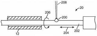
FIG. 4 illustrates an energy source suitable for use in the apparatus of the present invention, wherein the energy source delivers a fluid flow for tissue ablation;
FIG. 5 illustrates an energy source suitable for use in the apparatus of the present invention, wherein the energy source comprises a deflecting optical waveguide for delivering laser energy to prostate tissue;
FIG. 6 illustrates a device similar to that shown in FIG. 5, except that the optical waveguide directs the laser energy at a mirror that laterally deflects the laser energy;
FIG. 7 illustrates an energy source suitable for use in the device of the present invention, wherein the energy source comprises a laterally projecting electrode that can engage the urethral wall and prostate tissue in order to deliver radio frequency energy for tissue ablation;
FIG. 8 is a graph of tissue ablation rate exhibiting critical pressure;
FIG. 9a is a flow chart illustrating selective and controlled ablation;
FIG. 9b is a flow chart illustrating selective ablation wherein the fluid flow is configured to penetrate the urethral wall and ablate prostate tissue;
FIG. 10a illustrates columnar fluid flow and divergent fluid flow;
FIG. 10b illustrates a cross-sectional view of a tissue modification device configured to emit a columnar flow of fluid;
FIG. 10c illustrates a cross-sectional view of a tissue modification device configured to emit a divergent fluid stream;
FIG. 11 illustrates a tissue modification device using fluid flow for tissue ablation, wherein the fluid flow may optionally serve as a conduit for electromagnetic energy;
FIG. 12 illustrates components of a treatment probe according to an embodiment;
fig. 13A and 13B illustrate a system for treating a patient according to an embodiment;
figure 14A illustrates a multipurpose sheath and manifold, in accordance with an embodiment;
fig. 14B illustrates a manifold tube, such as the manifold in fig. 14A, configured to transmit and receive a plurality of fluids while the manifold remains coupled to a patient, in accordance with an embodiment;
FIG. 14C shows an assembly of a treatment probe and a linkage according to an embodiment;
FIG. 14D1 illustrates a quick swap of a carrier when a linkage is coupled with an elongate member anchored to a target site of an organ, according to an embodiment;
fig. 14D2 shows alignment of the distal tip of the carrier with the proximal end of the linkage for insertion into a carrier tube as in fig. 14D 1;
FIG. 14D3 shows the carrier being advanced toward the locking structure on the proximal end of the linkage as in FIG. 14D 1;
Fig. 14D4 shows the carrier locked to the link as in fig. 14D1 and 14D 2;
figure 14E illustrates the cystoscope at least partially inserted into an elongate element for advancement toward the bladder neck to view tissue of an organ, such as the prostate, in accordance with an embodiment;
fig. 14F shows advancement of the elongate element into the sheath;
fig. 14G illustrates a link coupled to an elongate element including a spine, in accordance with an embodiment;
FIG. 14H illustrates a carrier tube and carrier inserted into a connecting rod tube, according to an embodiment;
FIGS. 15 and 16 illustrate self-cleaning with a fluid jet, according to an embodiment;
figure 17A illustrates components of a user interface located on a display of a patient processing system as in figures 13A and 13B, according to an embodiment;
17B and 17C illustrate a marker moving over multiple images, where the movement of the marker corresponds to the position and orientation of the energy flow, according to an embodiment;
FIG. 17D illustrates a user-defined cutting profile in accordance with an embodiment;
17E and 17F illustrate a user interface for defining a plurality of curved portions of a cutting profile, according to an embodiment;
FIG. 18 illustrates a system configuration mode for a cut mode input of a user interface as in FIG. 17A;
FIG. 19 shows a coagulation mode selected with input from a user interface as in FIG. 17A;
figure 20A illustrates mapping and alignment of an image of a patient with a process coordinate reference frame, in accordance with an embodiment;
fig. 20B shows a method of treating a patient according to an embodiment;
21A and 21B illustrate screenshots of a 3d segmented image used in accordance with systems and methods of embodiments;
21C-21F illustrate a plurality of sagittal plane images of a target tissue used to define a three-dimensional treatment plan, and a user-defined treatment profile in each of the plurality of images;
FIG. 21G shows a transverse view of the target tissue and plane of the axial images of FIGS. 21C-21F;
FIG. 21H illustrates a three-dimensional treatment plan based on the plurality of images of FIGS. 21A-21F;
FIG. 21I illustrates a user input processing profile for an image among a plurality of images;
FIG. 21J illustrates a scan pattern of fluid flow according to an embodiment;
fig. 21K shows a bag containing a water hammer positioned on a fluid stream, in accordance with an embodiment;
22A and 22B show schematic views of a probe operating according to the principles of an embodiment;
FIG. 22C illustrates an endoscope placed in a working channel of an elongate member having a carrier to image tissue while treating a patient, in accordance with an embodiment;
Figures 23A and 23B illustrate a carrier configured to provide integrated jet delivery, in accordance with an embodiment;
figure 24 illustrates a carrier containing a fluid delivery element and design considerations for the fluid delivery element, according to an embodiment;
fig. 25A to 25C illustrate jet deflection according to an embodiment;
26A-26C illustrate a fluidic shield according to an embodiment;
fig. 27A and 27B illustrate jet angle changes according to embodiments;
FIG. 28 illustrates multiple jets delivered simultaneously in accordance with an embodiment;
FIG. 29 illustrates morcellation according to an embodiment;
fig. 30-31B show a single tube design according to an embodiment;
FIG. 32 illustrates a means of registering and positioning a processing system relative to a human anatomy, in accordance with an embodiment;
FIG. 33 illustrates a plurality of expandable structures including a first expandable basket and a second expandable basket, in accordance with an embodiment;
fig. 34 shows a means of registering a system with respect to a human anatomy according to an embodiment;
fig. 35 shows a disposable balloon according to an embodiment;
FIG. 36 illustrates tissue resection and depth control according to an embodiment;
FIG. 37 shows a visible entrainment region in the first size as shown in FIG. 36;
Fig. 38 illustrates tissue resection depth control according to an embodiment;
FIG. 39 shows an optical image of an entrainment region "flame" in the brine as shown in FIG. 38 having a different pressure than shown in FIGS. 36 and 37, in accordance with embodiments;
FIG. 40 illustrates nozzle flow rate versus maximum penetration depth for a plurality of pressures and nozzles, in accordance with an embodiment;
FIG. 41 illustrates nozzle back pressure and maximum penetration depth, in accordance with an embodiment;
fig. 42 shows nozzle flow rate versus back pressure for 130 micron nozzles and 150 micron nozzles, in accordance with an embodiment.
FIG. 43 shows a frequency spectrum of a jet configured to cut tissue in saline without impinging on the tissue, in accordance with an embodiment;
FIG. 44 shows a frequency spectrum of a jet of ablated tissue as in FIG. 43, wherein the frequency spectrum has an increase in high frequency content corresponding to the ablation of the tissue, in accordance with an embodiment;
FIG. 45 illustrates pressure regulation of a surgical site with substantially constant pressure and variable flow, according to an embodiment;
FIG. 46 illustrates flow regulation of a surgical site with a pump providing substantially fixed fluid flow and substantially constant pressure, according to an embodiment;
Figures 47A and 47B illustrate a transurethral treatment probe with an ultrasound array located near the fluid release member for imaging the treatment site;
FIG. 48A illustrates a user interface screen with process input parameters and process monitoring parameters, according to an embodiment;
FIG. 48B shows the user interface of FIG. 48A with real-time ultrasound images of a treatment site, according to an embodiment;
figures 49 and 50 illustrate side and isometric views, respectively, of a stiff sheath positioned over a transrectal ultrasound probe for inhibiting tissue shape changes as an elongate ultrasound probe is moved along an elongate axis of the ultrasound probe, in accordance with an embodiment;
fig. 51A illustrates a docking structure configured to engage a protrusion of a stiff sheath to hold the stiff sheath in place for a surgical procedure, in accordance with an embodiment;
fig. 51B shows a docking structure engaging the stiff sheath with the docking structure to support the stiff sheath and inhibit movement thereof during processing, wherein the docking structure is coupled to the lockable arm;
figures 52A and 52B illustrate isometric and cross-sectional views, respectively, of a treatment probe including a support structure having a dynamic tip, in accordance with an embodiment;
FIG. 53 illustrates venturi aspiration (venturi aspiration) into a probe with a channel configured to receive fluid near a nozzle of an ablation jet on the moving probe.
FIG. 54 illustrates a radio frequency (hereinafter "RF") electrode on a cauterization probe configured for rotation about the elongate shaft of the probe to cauterize tissue, according to an embodiment;
FIG. 55 illustrates a bipolar electrode configured for rotation about an elongate shaft of a cautery probe for cauterizing tissue, according to an embodiment;
FIG. 56 illustrates an integrated tissue treatment probe with suction and irrigation integrated into the probe, in accordance with an embodiment;
FIG. 57 shows an integrated treatment probe with an opening on the distal end for fluid aspiration, where the probe has been placed in a rigid sheath with an endoscope to view the treatment;
fig. 58 shows an integrated treatment probe having a suction opening and an irrigation opening on a distal end to suction through the suction opening and irrigation through the irrigation opening, where the probe has been placed in a rigid sheath with an endoscope to view the treatment, according to an embodiment.
Fig. 59A, 59B and 60 illustrate nozzle angles of a probe according to an embodiment;
Fig. 61, 62, and 63 are isometric, side, and cross-sectional views, respectively, of a treatment probe having a viewing path that is substantially concentric with a nozzle of a treatment jet, according to an embodiment.
Fig. 64 and 65 show an endoscope and a sliding telescopic structure for increasing rigidity and guiding the endoscope into a stiff sheath, according to an embodiment;
fig. 66 illustrates a treatment probe configured for at least partially manual treatment with an electrode and at least partially automated treatment with a water jet, in accordance with an embodiment;
FIG. 67 illustrates a treatment probe configured for at least partially manual treatment with a bipolar electrode and at least partially automated treatment with a liquid jet, according to an embodiment;
FIG. 68 shows a handpiece of the treatment probe as in FIGS. 66 and 67;
fig. 69 illustrates an ablation flame visible to the human eye, in accordance with an embodiment;
FIG. 70 shows a high-speed image of an ablation flame as in FIG. 69;
fig. 71 illustrates a plurality of shedding pulses and sweeping ablation jets to provide smooth and controlled tissue erosion over a plurality of overlapping locations, in accordance with an embodiment;
fig. 72 shows a catheter 950 for treating a patient, in accordance with an embodiment;
Fig. 73 shows the distal end of the catheter as in fig. 72, in accordance with an embodiment;
FIG. 74 illustrates a catheter placed in the working channel of a commercially available endoscope, according to an embodiment;
FIG. 75 illustrates placement of the catheter of FIGS. 72 and 73 of the endoscope of FIG. 74, and deflection of the distal ends of the endoscope and catheter, in accordance with an embodiment;
FIG. 76 illustrates maximum tissue penetration depth of a cut versus flow rate through a nozzle, according to an embodiment; and
FIG. 77 shows the selective removal of a potato as a model of selective tissue removal, wherein blood vessels are positioned over the incision in the potato.
Detailed Description
A better understanding of the features and advantages of the present disclosure will be obtained by reference to the following detailed description that sets forth illustrative embodiments, in which the principles of the embodiments of the invention are utilized, and the accompanying drawings.
While the detailed description contains many specifics, these should not be construed as limitations on the scope of the invention, but merely as illustrations of various examples and aspects of the invention. It should be understood that the scope of the present invention includes other embodiments not discussed in detail above. Various other changes, modifications and variations which will be apparent to those skilled in the art may be made in the arrangement, operation and details of the method and apparatus of the present invention disclosed herein without departing from the spirit and scope of the invention as described herein.
The embodiments disclosed herein can be combined in one or more of a number of ways to provide improved therapy for a patient. The disclosed embodiments can be combined with existing methods and devices to provide improved treatment, such as, for example, in combination with known prostate surgery and other tissue and organ surgical methods. It should be understood that any one or more of the structures and steps described herein can be combined with any one or more of the additional structures and steps of the methods and apparatus described herein, the figures and supporting text providing a description in accordance with embodiments.
Although the treatment planning and definition of treatment contours and volumes described herein are described in the context of prostate surgery, the methods and devices described herein may also be used to treat any body tissue and any body organs and vessels, such as the brain, heart, lung, intestine, eye, skin, kidney, liver, pancreas, stomach, uterus, ovary, testis, bladder, ear, nose, mouth, etc., soft tissues such as bone marrow, adipose tissue, muscle, gland and mucosal tissue, spinal cord and neural tissue, cartilage, hard biological tissues such as teeth, bones, and body cavities and passageways such as the sinuses, ureters, colon, esophagus, lung, blood vessels, and throat.
As used herein, the term AquablationTMIncluding ablation with water.
As used herein, the words "speculum", "endoscope", and "cystoscope" are used interchangeably.
As used herein, the terms "entrainment zone" and "cavitation zone" are used interchangeably.
The imaging and treatment probes described herein can be combined in one or more of a number of ways, and in many embodiments, images of the patient can be used to define the target volume and target profile of the removed tissue volume. The contour of the removed tissue can be planned for efficient tissue removal. The methods and apparatus for imaging described herein may be used to advantage to plan a treatment. Alternatively or in combination, the imaging methods and apparatus described herein may be used, for example, to modify a treatment in real-time as the patient receives the treatment.
The visible entrainment and cavitation regions may be combined with the images of the tissue and treatment area shown on the display to provide confirmation of the correct amount of tissue to be ablated. In many embodiments, the distance of the visible entrainment region corresponds to the maximum depth of cut, such that the surgeon may select the depth of cut based on the image and by adjusting a processing parameter such as one or more of flow rate, nozzle diameter, or pressure.
The visible entrainment region described herein includes a cavitation region of the fluid stream emitted from an energy source such as a nozzle, and the maximum ablation depth corresponds to the distance of the visible entrainment region. By visible entrainment region is meant that the user is able to visualize the entrainment region using imaging that is sensitive to the formation of cavitation vesicles, such as using visible light imaging and ultrasound imaging that scatter waves in response to the formation of cavitation vesicles.
Multiple carrier probes may be provided to allow a user to treat one or more of a number of tissues in a variety of ways. An elongate structural element having a working channel such as a shaft remains positioned within the patient while exchanging the first carrier probe with one or more carrier probes. In many embodiments, the carrier probe can be quickly exchanged while the linkage rod remains fixedly attached to the elongate element anchored to the internal structure of the patient. Each carrier probe inserted into the patient may be identified, for example, based on a treatment plan.
"processor," as used herein, includes one or more processors, e.g., a single processor, or multiple processors, e.g., of a distributed processing system. The controllers or processors described herein generally comprise tangible media to store instructions to implement process steps, and a processor may comprise one or more of a central processing unit, programmable array logic, gate array logic, or field programmable gate array, for example.
As used herein, the "transverse plane of an image" may be referred to as the horizontal plane of the image, the axial plane of the image, or the transaxial plane of the image. The image along the axial plane may be referred to as an axial image.
As used herein, a "probe" includes an object that is inserted into a subject, such as a patient.
As used herein, like characters and reference numerals identify like elements.
As used herein, a real-time image shown on a display includes an image shown within seconds of the event shown. For example, real-time imaging of tissue structures includes providing real-time images on a display within about 10 seconds of the acquired images.
As used herein, the terms "distal" and "proximal" refer to locations referenced from the device, and can be reversed from anatomical references. For example, a distal position of the probe may correspond to a proximal position of an elongated organ of a patient, and a proximal position of the probe may correspond to a distal position of the elongated organ of the patient.
Automated robotic control, in which the movement of the water jet is motorized and under computer control using preselected routines, allows for accurate and extremely fine ablation that is not possible with manual control. Advantages include reduced time required for the procedure, fewer complications, improved outcomes, and less training time required by the surgeon. Many of these improvements stem from the need to reduce or eliminate manual dexterity for the treating physician. Automated control also allows increasing the cutting power of the nozzle to a level that cannot be reached with full manual control. The system may be manually controlled during less critical portions of the procedure, for example, during initial selection of the region in which the operation is to be performed or during supplemental cutting and cauterization. The increased accuracy and smoothness provided by automated control may provide for the reduction and filtering of human hand jitter, even during those less critical phases of the protocol. Another significant advantage is that automation allows for pre-testing or "rehearsal" of the process. When selecting a cutting routine, a joystick or other control element may be used to select the limits of the area in order to position the laser during the simulation process without cutting. Changes may be made before the cutting begins so that errors can be corrected before the actual process begins.
Closed loop and real time automation are new functions provided by robotic automation including resection volume registration and in situ depth and volume measurement within an organ. With the ability to input organ geometry data (e.g., from ultrasound or other pre-operative or real-time images) into the control system, the cutting region can be accurately registered within the organ. This eliminates inaccuracies in manual procedures for important tolerances, such as how close the ablation should be to the surface of the capsule and/or the neurovascular bundle in the prostate. Furthermore, the shape of the volume to be removed itself can be selected and adjusted by a set of programmed routines, where details on how to control the cutting movement and pressure have been calculated in advance using a great deal of engineering knowledge and then stored in the robotic surgical tool ready to be accessed by the surgeon at any time by pressing a button. For example, the resection shape of the tissue may contain a predetermined treatment profile, such as one or more of a dome, cube, teardrop, or directly from a 3D rendering of the target volume as described herein and illustrated, for example, in the two screenshots of fig. 21A and 21B below. In addition, the surgeon can adjust the cutting parameters in real-time based on feedback provided by the ultrasound images, which adds another layer of safety to the system.
Is incorporated by reference
The subject matter of fig. 1 to 11 and the corresponding text described in the following documents have been incorporated by reference: U.S. patent No. 12/700,568 entitled "MULTI flip uid state reset METHODS AND DEVICES" filed on 2/4/2010 as disclosed in US 20110184391; and PCT application PCT/US2011/023781 entitled "MULTI FLUID device reset METHODS AND DEVICES" filed on 8.4.2007 as published on 8.11.2011097505 in 2011; the entire disclosures of the above documents have been previously incorporated herein by reference.
Referring to fig. 1, an exemplary prostate tissue debulking device 10 constructed in accordance with the principles of the present invention includes a catheter assembly generally comprising a shaft 12 having a distal end 14 and a proximal end 16. The shaft 12 will typically be a polymeric extrusion comprising 1, 2, 3, 4 or more axial lumens extending from the bushing 18 at the proximal end 16 to a location near the distal end 14. The shaft 12 will typically have a length ranging from 15cm to 25cm and a diameter ranging from 1mm to 10mm, typically from 2mm to 6 mm. The shaft will have sufficient column strength so that it can be introduced up through the male urethra as described in more detail below.
The shaft will include an energy source positioned in the energy delivery region 20, where the energy source can be any of a number of specific components as discussed in more detail below. Distal to the energy delivery zone, the expandable anchor balloon 24 will be positioned at the distal end 14 of the shaft or very close to the distal end 14. The balloon will be connected through one of the axial lumens to a balloon inflation source 26 connected through the hub 18. In addition to the energy source 22 and balloon inflation source 26, the hub optionally will also include a source for irrigation/irrigation 28, suction 30 and/or insufflation (pressurized CO)2Or other gas) source 32. In an exemplary embodiment, the irrigation or irrigation source 28 may be connected through an axial lumen (not shown) to one or more delivery ports 34 proximal of the balloon anchor 24 and distal of the energy delivery region 20. The aspiration source 30 may be connected to a second port or opening 36 that is generally positioned proximal of the energy delivery region 20, while the insufflating source 32 may be connected to an additional port 38 that is also generally positioned proximal of the energy delivery region. It should be understood that the location of the ports 34, 36 and 38 is not critical, although certain locations may result in the particular advantages described herein, and that the lumens and delivery devices may be provided by additional catheters, conduits, etc., including, for example, a coaxial sleeve, sheath, etc., which may be positioned over the shaft 12.
Although the present embodiment is described with reference to a human prostate, it should be understood that it can be used generally for treating a mammalian prostate. Referring now to fig. 2A-2D, a prostatic tissue debulking device 10 is introduced through the male urethra U to a region within the prostate P located proximate the distal end of the bladder B. The anatomy is shown in fig. 2A. Once the catheter 10 has been positioned such that the anchoring balloon 24 is located immediately at the distal end of the bladder neck BN (fig. 2B), the balloon may be inflated, preferably occupying substantially the entire interior of the bladder, as shown in fig. 2C. Once the anchoring balloon 24 is inflated, the position of the prostatic tissue volume reduction device 10 will be fixed and stabilized within the urethra U in order to position the energy delivery region 20 within the prostate P. It should be appreciated that proper positioning of the energy delivery region 20 is solely dependent upon inflation of the anchoring balloon 24 within the bladder. Since the prostate is located immediately proximal to the bladder neck BN, the delivery zone can be correctly positioned by spacing the distal end of the energy delivery zone very close to the proximal end of the balloon, typically in the range from 0mm to 5mm, preferably from 1mm to 3 mm. After the anchoring balloon 24 has been inflated, energy may be delivered into the prostate for debulking, as shown by the arrows in fig. 2C. As shown in fig. 2D, once the energy has been delivered over the desired surface area for a period of time, the energy region may be stopped and the prostate will be debulked to relieve the pressure on the urethra. At this point, as shown in fig. 2D, flushing fluid may be delivered through port 34 and sucked into port 36. Optionally, after treatment, the area may be cauterized using a cauterization balloon and/or stent that may be placed using a modified or separate catheter device.
Referring now to fig. 3-7, a number of representative energy delivery regions will be described. Referring now to fig. 3, a first exemplary prostatectomy device 110 constructed in accordance with the principles of the present invention includes a shaft 112, the shaft 112 having a proximal end 114 and a distal end 116. A plurality of nozzles 118 are mounted on shaft 112 at locations spaced proximally from distal end 116 by a distance ranging from 1cm to 5 cm. The nozzle, which is typically a ceramic core capable of generating a plasma or a port capable of directing a radially outward flow of electrically conductive fluid, may be mounted to the structure 120, which allows the nozzle 118 to move radially outward as shown in phantom in FIG. 3. An anchor 122, illustrated as an inflatable balloon, is mounted on the distal end 116 of the shaft 112 at a location between the nozzle 118 and the distal tip 124. As described in more detail below, the expandable structure 122 will be able to expand within the bladder to anchor the shaft 112, thereby leaving the nozzle array 118 within the prostate. The shaft 112 will include lumens, passageways, conductive wires, etc. for delivering energy and substances from the proximal end 114 to the distal end 116 of the shaft. For example, the RF energy source 126 would be connected to the shaft 112, typically to the nozzle 118, to deliver RF energy to the conductive fluid delivered to the nozzle 118 from the source 128 (typically via a lumen within the shaft 112). Additional lumens, channels or conduits will be provided to allow suction to the vacuum source 130, which is typically connected to one or more suction ports 132. Other conduits may be provided within the shaft 112 to allow introduction of an irrigation fluid, such as saline, from the source 134 to the port 136. In other instances, it will be possible to connect the aspiration source 130 and the irrigation source 134 to a common port so that aspiration and irrigation can occur sequentially rather than simultaneously. Further, optionally, an inner lumen, tubing, or the like may be provided to connect the insufflating source 140 to one or more insufflating ports 142 on the shaft in the region of the array 118. Finally, an inner lumen, conduit, or the like may be provided for connecting the balloon 122 to the balloon inflation source 144.
As shown in fig. 4, the example energy delivery region 20 may be formed by a high pressure nozzle 200 carried on a delivery tube 380 disposed within the shaft 12. The carrier tube 380 may be axially translated as indicated by arrow 204 and/or rotated as indicated by arrow 206 so that the fluid stream 208 emitted from the nozzle 200 may sweep or sweep over all or selected portions of the urethra within the prostate. Specific pressures and other details of such high pressure water treatment are described, for example, in Jian and Jiajun above.
Referring now to fig. 5, the energy source within the energy delivery region 20 may include a fiber optic waveguide or bundle 220 carried on a rotating and translating shaft 380. The optical waveguide 220 transmits laser or other coherent optical energy in a beam 222, which beam 222 can be swept or swept across the urethral wall and prostate tissue by rotating and/or translating the carrier tube 380.
As shown in fig. 6, laser energy from an optical waveguide or fiber bundle 230 can be directed axially to an optical mirror 232, where both the waveguide and the optical mirror are carried on a rotating and axially translating carrier tube 380. Again, by rotating and/or translating the carrier tube 380, the emitted light beam 234 may sweep or sweep over the urethral wall.
Referring now to FIG. 7, in another embodiment, a rotating and axially translating tube 380 can carry an electrode 240, the electrode 240 projecting laterally from the tube. The electrode 240 will be adapted for connection to a source of radiofrequency energy such that when the electrode contacts the urethral wall and prostate tissue, radiofrequency energy can be delivered in either a monopolar mode or a bipolar mode. Thus, the radiofrequency energy can ablate tissue at selected volumes and regions of the prostate. Optionally, the electrode 240 may also be used to cauterize tissue after it has been treated by altering the properties of the radio frequency energy.
In one embodiment of the invention, the device is configured to selectively resect tissue, thereby causing removal of some tissue components while leaving other tissue components intact. For example, the prostate and surrounding areas contain a variety of tissue components including glandular prostate tissue, blood vessels within the prostate, muscle fibers interstitium, cystic tissue, sphincters, seminal vesicles, and the like. When treating BPH or other prostate conditions, it is desirable to remove glandular prostate tissue and keep other tissues, such as blood vessels and cystic tissue, substantially undamaged.
As referred to herein, the term "resection" is intended to include any removal of tissue-including removal of one or more clumps of tissue cells, partial removal of tissue cells, and the like.
One advantage of treating BPH by selective tissue ablation is that there is a reduced need (or no need) for cauterization, since there is little or no damage to the blood vessels within the prostate, and thus limited bleeding. Another advantage resides in reducing the likelihood of incontinence or impotence, as selective resection reduces the risk of puncturing or otherwise damaging surrounding tissue such as the prostate capsule, sphincter, seminal vesicles, and the like.
When using a fluid stream to resect tissue, selective tissue resection may be achieved by varying one or more parameters of the fluid stream, such as the pressure within a nozzle or other fluid delivery element or the flow rate of fluid within the stream, so that it resects some tissue components while leaving other tissue components substantially intact.
In one embodiment, the fluid flow parameters may be configured to maintain non-target tissue substantially intact even when these tissues are exposed to the fluid flow for an extended period of time (i.e., typically a period of time sufficient to achieve the desired ablation). In another embodiment, the fluid flow parameters may be configured to ablate the target tissue at a rate substantially higher than the non-target tissue, thereby limiting damage to the non-target tissue. Such parameters may be adjusted according to the target tissue to be selectively ablated.
In one embodiment, the rate of ablation is configured to be higher for glandular tissue than for non-glandular tissue. The ablation rate may be configured by altering the pressure of the fluid as described above, or by adjusting other fluid parameters. In particular, the ablation rate for glandular tissue may be configured to be significantly higher than the ablation rate for non-glandular tissue, thereby effectively keeping the non-glandular tissue from being damaged during treatment. For example, the ablation rate of glandular tissue may be configured to be at least twice as high as the ablation rate for non-glandular tissue. As another example, the ablation rate for glandular tissue may be configured to be at least 10 times as high as the ablation rate for non-glandular tissue.
It should be noted that tissue resection has a critical pressure (below which tissue is not resected; above which tissue is resected) because the removal process involves tearing of the tissue, wherein the tissue is stretched on a microscopic scale to the point of rupturing or tearing the tissue stroma. Since the tissue is elastic, there will be a critical breaking point. Different types of tissue will have different critical breakpoints and therefore different critical pressures associated therewith.
In practice, given a particular fluid delivery element size (such as nozzle diameter), each tissue type typically has a critical pressure of the fluid flow source (hereinafter also referred to as Pcrit) below which the ablation rate approaches zero, and above which the ablation rate generally increases monotonically, and possibly exponentially. In particular, due to differences in tissue composition, the pressure of the fluid flow source may be configured to selectively ablate certain types of tissue while leaving other tissue types having higher critical pressures substantially undamaged.
An important aspect of resecting tissue in a multiple tissue environment according to the present embodiments is that it is possible to operate with a scheme in which one tissue type is resected while another tissue type remains substantially intact. This occurs most strongly when operating at pressures between the critical pressures for the two tissue types. As seen in fig. 8, the operating pressure P0 of the fluid flow may be configured to be greater than the critical pressure of tissue 1 (/ >, > Pcriti) to subject tissue 1 to an ablation rate greater than zero, while maintaining a pressure P0 less than the critical pressure of tissue 2 (P0< Pcrit2) to subject tissue 2 to an ablation rate substantially close to zero. In such a configuration, the fluid flow is said to be configured for selectively ablating tissue 1 rather than ablating tissue 2.
In one embodiment configured to treat BPH, the fluid stream source pressure is configured to be above the critical pressure of glandular prostate tissue but below the critical pressure of non-glandular prostate tissue. In such embodiments, the pressure is high enough to ablate glandular tissue, but too low to substantially ablate or damage non-glandular tissue such as blood vessels within the prostate, muscle fibro-stroma, cystic tissue, and the like. In one embodiment, the fluid is pressurized to a pressure in the range of about 1-30000psi, more preferably to a pressure in the range of about 50-1500psi, and most preferably to a pressure in the range of about 100-1000psi prior to exiting the fluid delivery element.
The following examples illustrate some of the critical pressures of tissue for fluid flow ablation. It should be noted that the following configurations are provided as examples and should not be construed as limiting.
Example 1: exemplary critical pressures for different kidney tissue constituents. Tissue critical pressure was measured in pig kidney. Kidney tissue is chosen because its composition is similar to that of prostate tissue. A columnar flow of fluid having a diameter of about 200 microns is used for tissue ablation. The glandular tissue (pink peripheral part of the kidney) is very soft and easily torn by the pressure of the fingers, while the inside of the kidney contains the tougher vascular tissue. The critical pressure of this fluid flow was found to be about 80psi for glandular tissue and about 500psi for vascular tissue, as seen in table 1 below.
Table 1 shows the different critical pressures of glandular and vascular tissues in pig kidney.
| Tissue of | P crit(psi) |
| |
80 |
| |
500 |
For example, experiments have shown that when pig kidneys are resected using a nozzle of about 200 microns in diameter at a source pressure of about 500psi, at 10cm2The ablation rate over an area is about 1cm per 30 seconds for glandular tissue (i.e., 10cc removed per 30 seconds) and less than about 0.1cm per 180 seconds for vascular tissue, which is about a 60-fold difference in ablation rate. Thus, in the same ablation time period, more glandular tissue will be ablated than vascular tissue. Thereby, the ablation time period may be configured to allow ablation of the glandular tissue without significant damage to the vascular tissue. The rate of ablation may be adjusted by varying the fluid source pressure and/or nozzle size. For example, the ablation rate for glandular tissue can be adjusted to approximately 1cc per minute,5cc per minute, 10cc per minute, 30cc per minute, or other rates. As discussed above, it should be understood herein that varying the size of the nozzle may necessitate varying the fluid source pressure in order to cause the fluid stream to impinge upon the tissue with sufficient force to achieve a desired ablation rate.
Figure 9a is a flow chart illustrating a method for selective prostate resection according to one embodiment. At step 700, the device is positioned and anchored in the urethra as described above. At step 701, various fluid parameters, such as pressure of a fluid source, shape of a fluid flow, etc., are configured to ablate a particular tissue type, such as glandular prostate tissue. By configuring the fluid parameters, fluid force, ablation rate, treatment time, tissue area to be ablated, etc. can be controlled to achieve controlled and selective ablation. After the parameters are configured, at step 702, the device is configured to discharge the flow of fluid to ablate the target tissue. At step 703, if it is determined that the treatment is complete, the device is withdrawn from the urethral U at step 704.
However, if it is determined at step 703 that the process has not been completed, the fluid parameters may be reconfigured as needed as described in step 701, and the loop of steps repeated until the process is completed. In particular, reconfiguration of the fluid parameters is advantageous in embodiments where it is desired to resect two different types of tissue for complete treatment. In such embodiments, fluid parameters may be adjusted to account for variations in the type of target tissue to be ablated.
Typically, other tissue types, such as vascular tissue or cystic tissue, will be exposed to the fluid flow after some or all of the glandular tissue has been excised. While the fluid flow parameters are configured for selective ablation of glandular tissue, it is also contemplated that the fluid parameters may be dynamically adjusted during the ablation process to account for gradual exposure of non-glandular tissue and to fine tune the selectivity of ablation as needed. After the fluid parameters are so reconfigured at step 701, the reconfigured fluid flow is then emitted at step 702 to continue tissue resection, and the operation continues until the treatment is complete.
In particular, it should be noted that when treating a prostate from within the urethra, the urethral wall is interposed between the source of the fluid stream (such as a nozzle or other fluid delivery element) and the target glandular prostate tissue to be resected.
Thus, in one embodiment, the fluid flow parameters are initially configured for ablating and penetrating a portion of urethral tissue (e.g., the urethral wall). However, since the composition of glandular prostate tissue is weaker than that of urethral tissue, it is desirable to avoid ablating glandular tissue using the same fluid flow forces used to ablate the urethral wall. To do this, the fluid flow may be used for a period of time sufficient to cut and penetrate the urethral wall, rather than for a longer period of time. Thereafter, the reduced intensity fluid stream can be used to ablate glandular prostate tissue.
Fig. 9b is a flow diagram illustrating a method for selective prostate resection, wherein the fluid flow is configured for first penetrating and resecting the urethral wall, according to one embodiment. At step 801, the device is positioned and anchored in the urethra as described above. At step 802, the device is configured to discharge a sufficiently forceful flow of fluid to ablate and penetrate the urethral wall. At step 803, after the fluid flow has penetrated the urethral wall, the fluid flow is adjusted to a level that selectively resects the desired prostate tissue while leaving the blood vessels, sacs, and other non-glandular tissue within the prostate substantially intact.
In addition, it is contemplated that the shape of the fluid flow also affects selective ablation. While the fluid flow is illustratively shown in fig. 10a as a columnar fluid flow 333 or a divergent fluid flow 334, it is also contemplated that the fluid flow may be any shape or configuration that allows for resection according to the present embodiments. In particular, as will be described further below, there are a number of advantages for columnar and divergent fluid flow configurations.
In the columnar fluid flow configuration 333, the device emits the fluid flow as a substantially concentrated rod-like fluid column having a substantially zero divergence angle. In one embodiment, the columnar fluid flow is configured as a substantially straight or non-divergent fluid flow. In such a configuration, the device substantially emits the fluid flow into a cylindrical or other non-diverging shape, thereby transmitting energy to the tissue over an area or spot size that is largely independent of the tissue distance from the fluid delivery element. Alternatively, the fluid flow may be regulated to converge, for example when the fluid delivery element comprises a plurality of nozzles or where the fluid contains bubbles, in order to concentrate the energy delivered to the tissue.
Figure 10b shows a cross-sectional view of a device emitting a columnar flow of fluid to remodel tissue such as the prostate. An elongate element 310 of the device, such as a shaft as described above, is placed within the urethra U. A fluid delivery element 320 disposed on a carrier tube (not shown) within the elongate member 310 is configured to emit a columnar fluid flow 333. As understood herein, the fluid delivery element 320 may comprise a nozzle as described above, or any other element configured to emit a fluid. The columnar fluid flow 333 is configured to cut tissue, such as the urethral wall UW and prostate tissue P, within the cutting region RA.
One characteristic of a columnar fluid flow configuration is: since the width of the ablation region RA is substantially independent of the fluid distance from the fluid delivery element 320, the ablation region RA remains substantially constant for a distance from the fluid delivery element 320. This is advantageous because the ablation region RA remains concentrated and constant as the fluid flow 333 travels away from the fluid delivery element 320, thereby delivering energy to the tissue in a concentrated area. The concentration of energy in the concentrated ablation zone RA is particularly advantageous when ablating or penetrating tough tissue such as the urethral wall UW. In one embodiment, the columnar shape of the fluid flow may be altered by introducing pressure fluctuations in the fluid delivery. For example, the columnar shape of the fluid flow may be altered by mechanically and controllably introducing a generally solid object in the fluid delivery path, such as after the aperture of the fluid delivery element 320 or in the path after the fluid flow exits the aperture of the fluid delivery element 320. In another example, the columnar shape of the fluid flow may be altered by introducing a vibrating element, such as a piezoelectric element, in the fluid path to create pressure fluctuations.
In another embodiment, the fluid flow is configured as a divergent fluid flow 334 as seen in fig. 10 a. Divergent fluid stream 334 is a stream that: where the fluid exits a fluid flow source, such as fluid delivery element 320, and diverges in a substantially conical shape, where the tip of the cone is at the fluid flow source. The ablation rate of the divergent fluid flow 334 may be expressed as a function of the distance z from the fluid delivery element 320 emitting the fluid to the tissue to be ablated. As shown in FIG. 10a, z ^ is farther away from the aperture than z/and, therefore, the ablation rate at z/is higher than at z ^.
The divergent fluid flow 334 may be characterized by the divergence angle of the fluid flow. In one embodiment, the divergence angle is configured to be about 0-90 degrees, more preferably about 2-45 degrees, more preferably about 4-20 degrees, and most preferably about 7 degrees, while also allowing for the divergence angle to be varied as desired.
Additionally, the divergent fluid flow 334 may be characterized by a cross-sectional shape of the fluid flow. Generally, the divergent fluid stream 334 has a cross-sectional area or spot size that is: it increases in distance further from the fluid flow source (e.g., fluid delivery element 320), thereby proportionally reducing the force per unit area of the fluid flow. This increase in spot size generally results in a greater ablation rate of tissue closer to the source of the fluid flow.
In one embodiment, the cross-sectional shape of the diverging fluid stream 334 is configured to be substantially a narrow rectangle (to create a fan-shaped fluid stream). In another embodiment, the cross-sectional shape of the diverging fluid flow 334 is configured to be substantially circular (to create a conical fluid flow) with the smallest cross-sectional area at the source of the fluid flow. It should be noted that the cross-sectional shape of the diverging fluid stream 334 may be configured in any shape that encompasses a non-zero area (e.g., an oval or irregular shape).
Figure 10c shows a cross-sectional view of a device emitting divergent fluid streams to remodel tissue such as the prostate. The elongate element 310 of the device is disposed within the urethra U. A fluid delivery element 320 disposed on a carrier tube (not shown) within elongate member 310 is configured to emit a divergent fluid flow 334. The divergent fluid flow 334 is configured for ablating tissue, such as the urethral wall UW and the prostate tissue P, within the ablation region RA. The ablation area RA covered by the divergent fluid flow 334 increases as the fluid flow travels away from the fluid delivery element 320, thereby proportionally decreasing the fluid flow intensity per unit area.
The divergent fluid flow 334 is characterized by an increase in ablation width as a function of distance from the fluid delivery element 320, while the ablation rate per unit area decreases as a function of distance from the fluid delivery element 320. This is because the total energy delivered in the fluid flow is generally constant (without taking into account any reduction in fluid velocity), but the energy is delivered over a larger area. Thus, the energy delivered per unit area is reduced, which is a key parameter on which the ablation rate depends. Thus, the ablation rate per unit area decreases as a function of distance.
Further, in the divergent fluid stream 334, the volumetric rate of ablation may be substantially constant as a function of distance. That is, although the ablation rate per unit area decreases, the total area ablated increases proportionately, and thus the total ablation volume remains substantially constant. It should be noted that if the area rate of ablation as a function of area energy density is non-linear and increases monotonically with energy, the volumetric rate of ablation will decrease as a function of distance from the fluid delivery element 320. It should also be noted that any deceleration of the fluid stream particles (e.g., droplets) will also cause the volumetric ablation rate to decrease as a function of distance.
Referring now to fig. 11, the device includes an elongated member 310, such as a shaft, the elongated member 310 configured for insertion into a body region. The elongate member 310 includes a window that exposes the carrier tube 380 and other components described below. The window reveals a carrier tube 380 and a high pressure fluid delivery element 320 disposed on the carrier tube 380. The fluid delivery element 320 is connected to a fluid source (not shown) via a fluid lumen 390, the fluid lumen 390 delivering fluid from the source to the fluid delivery element 320.
Alternatively, the elongate element 310 may be covered by a sheath or other covering (not shown) as the elongate element 310 is introduced through the urethra. When fully covered with the sheath, the window is protected, thereby reducing scratching and damage to the urethra as the elongate member 310 is advanced. Once in place, the sheath is retracted, exposing the window. The carrier tube 380 may then be rotated and advanced and/or retracted to deliver fluid through the fluid delivery element 320.
Additionally and optionally, the device may include a shield element (not shown) positioned to substantially cover the fluid delivery element 320 while maintaining a space between the fluid delivery element 320 and the shield element. This in turn effectively maintains the space between the fluid delivery element 320 and any tissue that may impinge on the shield element. In one embodiment, the shield element is a substantially flat sheet-like element positioned over the fluid delivery element 320. The shield member is positioned or shaped such that it allows the carrier tube 380 to move within the elongated member 310 as desired. For example, the shield element may be curved to follow the curvature of the carrier tube 380. The shield element includes openings for allowing the fluid stream emitted by the fluid delivery element 320 to pass unobstructed therethrough and impinge on the tissue. The opening may be circular, or it may comprise other shapes. One advantage of such a shield element is that it protects the fluid delivery element 320 from damage during insertion or removal processes and/or during handling. Another advantage of the shield element is that during or after fluid firing, fluid returning to the fluid delivery element 320 can pass through the shield element opening (or through other paths around the shield element) and into the space between the shield element and the fluid delivery element 320. Such return fluid may then be directed out of the space such that fluid emission is not obstructed or impeded by such return fluid.
The shield element may also be configured such that the space between the shield element and the fluid delivery element 320 is in continuous communication with the waste disposal chamber via a low flow resistance fluid path. This creates a low flow resistance path between the fluid delivery element 320 and the external destination of such waste, so that waste and fluid exiting the fluid delivery element 320 can easily exit the area around the fluid delivery element 320. In this context, low resistance should be understood to mean a low flow resistance compared to the flow resistance of the fluid delivery element 320. This configuration advantageously prevents back pressure at the fluid delivery element 320 that would otherwise reduce flow and thereby allow the fluid stream emitted by the fluid delivery element 320 to travel substantially undisturbed by waste and return fluid.
The fluid delivery element 320 may be a single nozzle, a plurality of nozzles, or an array of nozzles in various configurations. The fluid delivery element 320 is configured to emit fluid radially outward as a fluid stream 331 with sufficient force to cause the fluid stream 331 to ablate tissue upon contact with the tissue. The fluid flow 331 may be perpendicular to the elongated element 310, or it may be configured at various angles relative to the elongated element 310.
The carrier tube 380 may be axially translated, rotated, oscillated, or rotationally oscillated relative to the elongate member 310 such that the fluid flow 331 may sweep or sweep a desired tissue area or volume for ablation. The desired area or volume may be a sphere, a cylinder, or any other predetermined area or volume of any shape and size.
Additionally and optionally, when the device is not being used to resect tissue, the carrier tube 380 can be positioned such that the fluid delivery element 320 and/or any other elements (such as a visualization element or cauterization element) are located away from the window, thereby reducing the risk of damage to such elements, as well as reducing the risk of any accidental resection of tissue.
The device further comprises at least one insufflating port 340 disposed on the elongate member 310. The insufflating port 340 is connected to an insufflating source (not shown) via one or more lumens, wherein the insufflating source delivers fluid 330 through the insufflating port 340 and into the body region in order to distend the surrounding tissue and create a working space. The apparatus also includes at least one removal port 360 for removing debris products, such as resection products, resection fluid, other waste products, or mixtures thereof. The elongate element 310 may include a lumen, passageway, conductive wire, etc., configured for delivering energy and/or substances from the proximal end to the distal end of the elongate element 310, and/or for removing debris and waste products, the details of which are described above.
Optionally, in addition to fluid delivery element 320, the device may include an electromagnetic energy delivery port 350, port 350 being disposed on carrier tube 380 and located in or near fluid delivery element 320. As also described in more detail above, electromagnetic energy 332 is delivered to energy delivery port 350 by means of one or more conduits 351, such as a carrier tube 380 and an optical fiber or other waveguide within elongate element 310. The electromagnetic energy 332 may be radio frequency energy, coherent or incoherent light, or any other form of electromagnetic energy. The energy delivery port 350 is configured to deliver energy 332 through the interior of the fluid stream 331 so that the electromagnetic energy 332 may ablate tissue in lieu of or in combination with fluid ablation.
Additionally and optionally, the various forms of electromagnetic energy described above may be configured to combine with tissue ablation, or cauterize tissue independently thereof. Because the selective tissue removal disclosed herein generally results in little or no damage to the remaining tissue, such as vascular tissue, and thus limited or no bleeding, such cauterization need only be used on a limited basis if desired. It is contemplated that when electromagnetic energy is delivered to the tissue for cauterization through fluid flow 331, the fluid source pressure may be adjusted to be substantially below the critical pressure for tissue resection so that additional tissue is not resected.
Alternatively or additionally, cauterization may be achieved using other means, for example, using a cauterization balloon and/or stent placed in contact with the tissue using a catheter device as described above.
Further, the device may include an optional deflecting element, e.g., positioned within the inner or elongate member 310 and distal to the window, configured to deflect fluid emitted by the fluid delivery element 320 back toward the fluid delivery element 320, thereby removing any debris that may have accumulated on the fluid delivery element 320 and/or the energy delivery port 350 during tissue resection. Further, the fluid delivery element 320, in combination with the deflection element, may be configured to clean substantially the entire fluid delivery element 320, any visualization or cauterization elements, and/or the carrier tube 380, or a portion thereof. The deflecting element may be configured to be substantially flat or concave. Alternatively, the deflecting element may be configured in any shape or design.
Additionally, the deflection element may be configured to function as a protection element for the fluid delivery element. The fluid delivery element can be positioned in a particular location relative to the protective element that protects the prostate from accidental fluid emission, and for example, protects the fluid delivery element 320 from clogging or blockage by tissue, particularly during insertion and removal from the body.
The carrier tube 380 includes a carrier. The carrier may optionally comprise a tubular structure. Although reference is made to carrier tube 380 in accordance with embodiments, the carrier can also include a cross-section that is not substantially tubular, e.g., a rectangular cross-section extending along a majority of the carrier as described herein. Thus, it should be understood that although a carrier tube is shown and described in the figures, the carrier may also include a non-circular carrier in each of the figures and the support text described herein.
FIG. 12 illustrates components of a treatment probe 350 according to an embodiment. The carrier tube 380 includes a concentric configuration of first and second fluid delivery ports. The fluid delivery element 320 releases a fluid flow 331. The fluid flow 331 defines an axis extending outwardly from the fluid delivery element 320. Fluid flow 331 may include a diverging flow 334 or a columnar flow 333 as described herein. The fluid delivery element 320 includes a nozzle 322. The nozzle 322 may include a substantially circular cross-section. The nozzle 322 may include an internal passage having a circular cross-section, wherein the internal passage extends cylindrically. The internal passage extends along an axis corresponding to the axis of fluid flow 331.
The port 340 is disposed concentrically around the fluid delivery element 320. The port 340 includes a substantially annular channel extending circumferentially around the fluid delivery element 320 and the nozzle 322. The port 340 may comprise an injection port as described herein. The ports 340 release the fluid 330 in a substantially concentric arrangement with the fluid flow 331. The substantially concentric arrangement has the following advantages: which provides a sheath around the fluid flow 331 with the first fluid 330 extending outwardly from the port 340 to advantageously direct the treatment flow toward the tissue. The energy conduit 351 extends from an energy source, such as a laser, toward the fluid delivery element 320. The energy conduit may, for example, comprise an optical fiber or a plurality of optical fibers coupled to a laser. The optical fiber may extend toward the nozzle 322 and may be concentrically aligned with an axis defined by the nozzle 322 so as to provide efficient energy transfer through the nozzle 322 of the optical energy emitted from the optical fiber. Structures may be provided near the distal end of the optical fiber to align the optical fiber with the channel of the nozzle 322. The concentric alignment of the optical fibers, nozzles, and ports 340 can provide a patient treatment that allows visualization and treatment of the patient. The fluid released from port 340 may comprise a liquid, such as saline, or a gas, such as CO 2. The fluid delivered through the port 340 may be selected by a user using the interface described herein.
The fluid flow 331 may provide an optical waveguide directed at the tissue. In many embodiments, fluid flow 331 has a greater index of refraction than the fluid released through port 340. The waveguide medium may be a liquid or a gas, and the jacket medium released from the port 340 may be a liquid or a gas. An intermediate medium may be located between the probe and the target tissue. The intermediate medium may be a liquid or a gas, for example, one or more of brine, air or carbon dioxide. In many embodiments, the intermediate medium includes fluid released from the nozzles 322 and fluid released from the annular port 340.
Fig. 13A and 13B illustrate a system for treating a patient according to an embodiment. The system 400 includes a treatment probe 450 and optionally an imaging probe 460. The treatment probe 450 is coupled to the console 420 and the linkage 430. The imaging probe 460 is coupled to an imaging console 490. The patient treatment probe 450 and the imaging probe 460 may be coupled to a common base 440. The patient is supported by a patient support 449. The treatment probe 450 is coupled to the base 440 with an arm 442. The imaging probe 460 is coupled to the base 440 with an arm 444.
The patient is placed on the patient support 449 so that the treatment probe 450 and the ultrasound probe 460 can be inserted into the patient. The patient may be placed in one or more of a number of positions, such as, for example, a prone position, a supine position, an upright position, or an inclined position. In many embodiments, the patient is placed in the lithotomy position, and a foot stirrup may be used, for example. In many embodiments, the treatment probe 450 is inserted into the patient in a first orientation on a first side of the patient and the imaging probe is inserted into the patient in a second orientation on a second side of the patient. For example, the treatment probe may be inserted into the patient's urethra from the patient's anterior side, and the imaging probe may be inserted into the patient's intestine transrectally from the patient's posterior side. The treatment probe and the imaging probe may be positioned within the patient with urethral tissue, urethral wall tissue, prostatic tissue, intestinal tissue, or intestinal wall tissue extending therebetween.
The treatment probe 450 and the imaging probe 460 can be inserted into the patient in one or more of a number of ways. During insertion, each arm may include a substantially unlocked configuration to enable desired rotation and translation of the probe to insert the probe into the patient. When the probe has been inserted to the desired position, the arm can be locked. In the locked configuration, the probes can be oriented relative to each other in one or more of a number of ways, such as parallel, oblique, horizontal, oblique, or non-parallel, for example. It may be helpful to determine the orientation of the probe using an angle sensor as described herein in order to map the image data of the imaging probe to a processing probe coordinate reference. Mapping tissue image data to a treatment probe coordinate reference space may allow for accurate targeting and treatment of tissue identified for treatment by an operator, such as a physician.
In many embodiments, the processing probe 450 is coupled to the imaging probe 460. To align the process with the probe 450 based on the image from the imaging probe 460. The coupling may be accomplished with a common base 440 as shown. Alternatively or in combination, the treatment probe and/or imaging probe may include a magnet to keep the probes aligned while passing through the patient's tissue. In many embodiments, the arm 442 is a movable and lockable arm to enable positioning of the treatment probe 450 at a desired location within the patient. When the probe 450 has been positioned in the desired position on the patient, the arm 442 may be locked with the arm lock 427. The imaging probe may be coupled to the base 440 with an arm 444, which may be used to adjust the alignment of the probe when the treatment probe is locked in place. Arm 444 may, for example, comprise a lockable and movable probe under control of an imaging system or console and user interface. The movable arm 444 may be micro-actuatable to enable adjustment of the imaging probe 440 relative to the treatment probe 450 with a small movement (e.g., on the order of 1 millimeter).
In many embodiments, the treatment probe 450 and the imaging probe 460 are coupled to an angle sensor to enable control of the treatment based on the alignment of the imaging probe 460 with the treatment probe 450. The angle sensor 495 is coupled to the imaging probe 450 with a support 438. The angle sensor 497 is coupled to the imaging probe 460. The angle sensor may comprise one or more of many types of angle sensors. For example, the angle sensor may include an goniometer, an accelerometer, and combinations thereof. In many embodiments, the angle sensor 495 comprises a 3-dimensional accelerometer to determine the three-dimensional orientation of the treatment probe 450. In many embodiments, angle sensor 497 includes a 3-dimensional accelerometer to determine the three-dimensional orientation of imaging probe 460. Alternatively or in combination, the angle sensor 495 can include an goniometer to determine the angle of the treatment probe 450 along the elongate axis of the treatment probe. The angle sensor 497 may comprise an goniometer to determine the angle of the imaging probe 460 along the elongate axis of the imaging probe 460. The angle sensor 495 is coupled to the controller 424. The imaging probe's angle sensor 497 is coupled to the processor 492 of the imaging system 490. Alternatively, and in combination, the angle sensor 497 may be coupled to the controller 424.
The console 420 includes a display 425, the display 425 being coupled to a processor system in the assembly for controlling the treatment probe 450. The console 420 includes a processor 423 with a memory 421. The communication circuit 422 is coupled to the processor 423 and the controller 422. The communication circuit 422 is coupled to an imaging system 490. Console 420 includes the components of endoscope 35 coupled to anchor 24. The irrigation control 28 is coupled to the probe 450 to control irrigation and irrigation. An attraction control 30 is coupled to the probe 450 to control attraction. The endoscope 426 may be a component of the console 420, and may be an endoscope that is insertable with the probe 450 for treatment of a patient. An arm lock 427 of the console 420 is coupled to the arm 422 to lock the arm 422 or allow the arm 422 to move freely to insert the probe 450 into the patient.
The console 420 may include a pump 419, the pump 419 being coupled to the carrier and the nozzle as described herein.
The processor, controller, and control electronics and circuitry may include one or more of a number of suitable components, such as one or more processors, one or more Field Programmable Gate Arrays (FPGAs), and one or more memory storage devices. In many embodiments, the control electronics control a control panel of a graphical user interface (hereinafter "GUI") to provide preoperative planning in accordance with user-specified processing parameters, and to provide user control of the surgical procedure.
The treatment probe 450 includes an anchor 24. The anchor 24 anchors the distal end of the probe 450 while the probe 450 is delivering energy to the energy delivery region 20. The probe 450 may include the nozzle 200 as described herein. The probe 450 is coupled to the arm 422 using a linkage 430.
The elongate shaft of the probe 450 generally extends between a proximal portion of the probe 450 near the linkage 430 and a distal end having an anchor 24 attached thereto. The third portion 436 controls the angle of rotation about the elongated shaft. During treatment of a patient, the distance 439 between the treatment region 20 and the fixed portion of the linkage changes with the reference distance 439. The distance 439 is adjusted in response to computer control to set the target location of the reference anchor 24 along the elongate axis of the treatment probe. The first portion of the linkage remains stationary while the second portion 434 adjusts the position of the treatment region along the axis. The third part 436 of the linkage adjusts the angle about the axis in response to the controller 424 so that the distance along the axis at the angle of treatment can be controlled very accurately with reference to the anchor 24. Probe 450 may include a rigid member, such as a spine, extending between support 438 and anchor 24 such that the distance from linkage 430 to anchor 24 remains substantially constant during treatment. The treatment probe 450 is coupled to a treatment assembly as described herein to allow treatment with one or more forms of energy, such as mechanical energy from a jet, electrical energy from an electrode, or optical energy from a light source, such as a laser source. The light source may comprise infrared, visible or ultraviolet light. The energy delivery region 20 is movable under the control of the linkage 430 to deliver a predetermined form of energy to the target tissue of the patient.
Figure 14A illustrates a multipurpose sheath and manifold, according to an embodiment. Manifold 468 is configured to deliver a plurality of fluids to and from a work site. Manifold 468 is rigidly coupled to (e.g., affixed to) spine 452. Sheath 458 is positioned about spine 452 and may extend inwardly toward manifold 468. Manifold 468 is coupled to support 438 in linkage 430 with locking element 460. Manifold 468 may be decoupled from link 430 and support 438 to remove link 430 and support 438, allowing additional components to be inserted into the working channel. For example, an endoscope may be inserted into the working channel so that it extends toward the working area of the organ (e.g., prostate). Structure 462, which includes a nose, extends toward manifold 468. Structure 462 is shaped to engage manifold 468 and allow structure 462, link 430, and support 438 to be removed when locking element 460 is disengaged. Manifold 468 includes structure 464 to engage in a nose of structure 462. A plurality of seals are disposed on the manifold 468 to allow for removal of the structure 462. When the structure 462 has been removed, an endoscope or other surgical tool can be inserted into the workspace and advanced toward the treatment site. For example, the endoscope may be advanced toward a treatment site to be a treatment area. The manifold includes a plurality of ports coupled to the treatment site to allow for the transfer and removal of fluids from the treatment site. For example, when the endoscope has been placed at the treatment site. The locking element and manifold allow the linkage rod and treatment probe to be removed so that manifold 468 remains coupled to sheath 458 and spine 452 within the patient.
In many embodiments, the treatment probes and carriers described herein, e.g., tubular carriers, can be inserted and removed while the locking element 460 engages the linkage 430 and the support 438. Such a configuration of the linkage, locking element and support allows for quick and easy removal and reinsertion of the probe to provide advantageous handling.
The multipurpose sheath and manifold described herein have the following advantages: which allows the sheath, manifold, spinal rod, and anchor to remain attached to the patient while additional surgical tools are employed. The locking element cooperates with a plurality of instruments allowing placement, visualization and
aquableton and aquabeam operate without reintroduction or movement relative to the tissue. The multiple sealed conduits allow the use of a sheath port to transmit the flow or pressure of different fluids within or parallel to the working channel. The working channel may be used for visual access to the anatomy via existing rigid or flexible endoscopic techniques. The working channel has a large caliber to accommodate many types of tools and to allow free flow of tissue and fluids. Alternative energy delivery devices may be used within the sheath or working channel described herein.
In many embodiments, the working channel is sized to allow a plurality of carriers to be positioned within the working channel. For example, an endoscope carrier is positioned within the working channel and a treatment probe as described herein is positioned within the working channel to allow visualization of the treatment site while the treatment probe is performing aquastration (tm) and aquabeam operations as described herein.
Fig. 14B illustrates a manifold conduit of the manifold configured to transmit and receive multiple fluids while the manifold remains coupled to the patient. The manifold is coupled to a plurality of ports 456. The plurality of ports 456 can include an auxiliary fluid port 456A, a balloon pressure port 456B, and a tissue removal port 456C. Sheath 458 extends circumferentially around spine 452. The spine 452 and sheath 458 may be rigidly coupled to the manifold portion and provide connections and channels coupled to the manifold portion. A channel 467, e.g., a tubular channel, is connected to port 456B to allow for inflation of the balloon. The channel 469 may be defined by a sheath 458. The channel 469 may be coupled to the port 456A to provide auxiliary fluid to the treatment site. A port 456C to allow tissue removal may be coupled to the main working channel 465. A main working channel 465 may extend from port 456C to the treatment site. A plurality of seals 466 are arranged to separate processing ports and channels as described herein. Manifold 468 may be decoupled from linkage 430 and support 438, and allows balloon inflation pressure to be applied through port 456B. Auxiliary fluid may be provided, for example, through port 456A, to flush working channel 465. Such a configuration of the manifold allows the spine 452 and anchors 24 to remain in place when other instruments have been inserted into the working channel.
The multiple manifold conduits described herein allow for routing of tissue collection through the large bore working channel 469 to reduce flow obstructions. Balloon pressure may be transmitted from the luer fitting to the distal tip of the anchor with a small diameter tube (e.g., the tube defining channel 467). Channels 469 are used to transport the auxiliary fluid between the sheath and the spinal rod to the treatment area.
Figure 14C shows the process probe and link assembly disassembled prior to use. Linkage 430 includes a housing 410 and a cover 412. A cover 412 may be placed on the lower portion of the housing 410. The cover and housing may comprise rigid materials to increase rigidity. The housing and cover can be sized to form a hand piece containing the linkage 430. The linkage 430 includes an elongated tubular structure including a gear 433 to engage another gear 434 of the linkage. The gear 434 may be positioned on the movable carriage 413. The elongated tubular structure may include a second movable portion 436 of the linkage. The housing 410 may include a support 438 for the linkage. The gear 433 remains connected to the elongated tubular structure 431 while the linkage is disassembled. The movable portion of the linkage 430 may include a gear 433, a gear 434, and a movable bracket 413 to distally advance the elongated structure 431 when connected to the second movable portion 436, as indicated by arrow 418. The lid 412 includes a flange 416. When the cover is placed on the housing, the elongated structure may be locked to the link at location 431.
The elongate element 310 includes a spine 452 as described herein and is shown covered by a sheath 458. Sheath 458 includes a channel to receive elongate member 310. The elongate element 310 includes a working channel and is insertable into the sheath 458 such that the elongate element is covered by the sheath 458. Sheath 458 and elongate element 310 are shown connected to a manifold 468 as described herein.
The elongated element 310 is configured to be slid into the sheath 458 such that the elongated element 310 and the sheath comprise a locked configuration. The elongated member 310 includes a structure 411, the structure 411 configured to engage the housing 410 of the linkage such that when the elongated structure 431 is moved as described herein, the elongated member 310 and the housing 410 remain substantially stationary.
In many embodiments, housing 410 includes support 438. The support 438 may comprise a substantially non-moving portion of the linkage 430 described herein. Linkage 430 may include a movement bracket 433 to move carrier 382 while housing 410 including support 438 remains locked to the arm and does not move substantially as described herein.
In many embodiments, the structure 411 of the elongated member 310 includes a locking structure to form a locking junction with the housing 410 and the cover 412.
In many embodiments, the manifold 468 is connected to the sheath 458 and may be affixed to the sheath in order to insert the sheath 458 into the patient and inflate the balloon anchor 24 with the manifold 468 as described herein. The elongate element 310 including the spine 452 may then be inserted into the sheath 458. The manifold 468 and structure 411 include a locking structure 417 to lock the manifold to the elongated element 310 when the elongated element 310 has been inserted into the manifold 468 and sheath 458. Release 415 may be depressed by a user to unlock manifold 468 from elongate member 310.
The elongated tubular structure 431 of the linkage 430 includes structure to receive the carrier tube 380. The opening 409 of the elongated tubular structure 431 is sized to receive the carrier tube 380. The connecting structure 408 is shown on the proximal end of the linkage and includes a locking structure 406 for receiving the protrusion 404 of the connecting structure 405 of the carrier tube 308.
Fig. 14D1 shows a quick swap of carrier tube 380 when linkage 430 is coupled with elongate member 310 anchored to a target location of an organ. The elongated element 410 may be inserted into or removed from the linkage by a user. The elongate element 380 can be advanced into the opening 409 adjacent the connection structure 405 of the elongate tubular structure 431.
The imaging probe 460 may be mounted on the second link and configured to move with the nozzle of the carrier 382 to image the interaction of the energy flow from the carrier 382 as the tissue is treated. The processed images may include axial and sagittal images from the imaging probe 460. The linkage may be coupled to a controller or processor as described herein (or both) to move the imaging probe 460 in synchronization with the carrier 382 and the nozzle of the carrier, e.g., along an axis. The imaging probe 460 may comprise a transrectal ultrasound probe and the carrier 482 may comprise components of a treatment probe 450 as described herein.
Fig. 14D2 shows the distal end of carrier 382 aligned with opening 409 of the proximal end of elongated tubular structure 431 for insertion of carrier tube 380 as in fig. 14D 1.
Fig. 14D3 shows the carrier being advanced toward the locking structure 406 on the proximal end of the linkage as in fig. 14D 1. The locking structure 406 is sized to receive the tab 404 to form the locking joint 402.
Fig. 14D4 shows carrier tube 380 locked to link 430 as in fig. 14D1 and 14D 2. The tab 404 has been inserted into an opening of the locking structure 406 to form a locking joint. The joint may be unlocked by manipulation by a user.
Fig. 14E shows the cystoscope inserted at least partially into sheath 458 for advancement toward the anchoring location of the organ. The anchoring location may include the bladder neck to view tissue of an organ such as the prostate. Sheath 458 described herein may be advanced to a target location using visualization from a cystoscope placed within the working channel of elongate element 310. When an anchor 24, such as a balloon, is positioned, it may be inflated with a port of the manifold 468 coupled to a sheath as described herein.
Embodiments described herein are possible with at least two forms of visualization. 1.)
The cystoscope is locked within sheath 458. The goal may be to view the prostate and then ultimately leave the sheath as a safe channel to guide the elongate element 310 including the spine 452 into the patient, without having direct visualization in many embodiments. The distal end of the sheath is flush near the bladder neck. 2.) once elongate element 310 is locked into sheath 458, the patient can be viewed using a ureteroscope. The ureteroscope may be inserted into the same channel as the channel into which the carrier 380 is entered, e.g., into a common channel.
Fig. 14F shows advancement of the elongate element 310 into the sheath 458. The manifold 468 on the proximal end of the sheath 458 may include a locking structure to receive a locking structure on the proximal end of the elongate member 310. The elongate element 310 may be advanced into the sheath 458 such that the sheath 458 and the locking element on the elongate element 310 engage.
Fig. 14G shows a link 430 coupled to an elongate member 310 that includes a spine 452. The link is configured to receive a carrier 382 and a carrier tube 380 as described herein.
Fig. 14H shows a carrier tube and carrier inserted into the connector tube described herein in a locked configuration.
Fig. 14A-14H illustrate a method of treating a patient according to an embodiment, and each of these figures illustrates one or more optional steps of the method.
Figures 15 and 16 illustrate self-cleaning with fluid jets as described herein. As described herein, a fluid jet (e.g., fluid stream) can be used to purge the working channel and clear tissue or other ports within the multifunctional sheath. Self-cleaning can be automated or performed manually. In addition, the water jet intensity can be reduced to clean the laser camera or other auxiliary device without removing the device from the working channel. For example, the endoscope may be sized to fit within the working channel, or alternatively, the endoscope may be sized to fit within the working channel with the linkage decoupled and allow flushing and cleaning of the working channel. Alternatively or in combination, the carrier 382, which may include a carrier tube 380, may be sized to fit within the working channel with the endoscope so as to allow for cleaning of the endoscope.
In many embodiments, self-cleaning can be employed with a probe containing a carrier 382, which can include a carrier tube 380, positioned within the working channel. The elongated element 310, including the sheath and the spinal rod, may house a carrier 382, which carrier 382 may include a carrier tube 380 along a substantial portion of the carrier. The carrier 382 may, for example, comprise a rectangular or tubular end and may comprise a portion having a cylindrical or tubular geometry. The fluid stream released from carrier 382 may, for example, extend divergently to distance 457. Alternatively, the fluid flow may comprise a columnar fluid flow. A linkage may be used to control the angle of the fluid flow 453 to rotate the fluid flow during cleaning. The fluid flow may increase or decrease in pressure.
A fluid jet may be used to clean the working channel and remove tissue or other parts within the multifunctional sheath. This may be automated or performed manually. Alternatively, the water jet intensity may be reduced to clean the laser camera or other auxiliary device without removing the device from the working channel.
Fig. 17A shows the components of the user interface 500 on the display 425 of the system 400. The display 425 may, for example, comprise a touch screen display, alternatively or in combination, the display 425 may be coupled to a pointing device, keyboard, and other known user input devices for working with the processor system. Interface 500 includes an operations tab 502, a CO2 monitoring tab 504, and a system configuration tab 506. The user interface 500 includes buttons 507 on the display to adjust values entered into the computer system up or down. A stop button 503 is provided on the user interface for the user to stop the treatment of the patient. A start button 501 is provided for the user to start the treatment of the patient. The user interface 500 includes an image 510 of an organ, such as the prostate. The image 510 shown may be an image of one or more of a number of organs as described herein. The image 510 may, for example, include a prostate image from an anatomical image corresponding to the prostate of the patient. Image 510 is shown in an axial trans-axial cross-sectional view having a front orientation and a rear orientation, with image 510 also shown along the longitudinal axis. The sagittal view of image 510 along the longitudinal axis illustrates anchor 24 and a lumen such as a urethra. Image 510 may include an image of a patient to be processed, e.g., an ultrasound image of the patient. Image 510 can be illustrated in axial and sagittal views, with the ultrasound image sized to correspond to the treatment profile shown on display 425.
The user interface 500 includes a plurality of inputs. The plurality of inputs may include one or more of the following inputs as described herein.
The plurality of angular input parameters 550 may, for example, include an input 552 and an input 554. An angular orientation may be provided so as to align with the anteroposterior direction of the patient extending between axis 530 and indicia 534. Input 522 may be used, for example, to adjust the angular orientation of the treatment about axis 530 when the patient and probe are aligned at slightly different angles. Input 522 is rotationally aligned about an axis, in units of angles, to the center of the processing profile. The input 554 provides a sweep angle from one angular extreme to another, for example, the sweep angle may include an angle less than 360 °, e.g., 240 °. The sweep angle generally extends around the front-to-back treatment axis and extends from the front-end treatment backside treatment axis a distance of about half the sweep angle, e.g., 120 ° swept in a first direction and 120 ° swept in an opposite direction from the front-to-back treatment axis. In many embodiments, the sweep angle is limited to less than 360 degrees to avoid sweeping the fluid flow into the spinal rod.
The angular position of the stream can be shown on the display in real time, with the output 556 of the angular position being in degrees. The output angle may be shown on the display as a moving color line (e.g., green) that is swept around the axis 530.
A plurality of input parameters 560 may be used to determine a treatment range along axis 451 and axis 530. The inputs 562 determine the position of the treatment profile relative to the expandable anchor 24. Input 564 determines the length of the process along axis 451 and axis 530. The input 564 may include a processed longitudinal distance extending from the first end 524 to the second end 528. Input 570 may determine a radius of the processing profile about axis 530. Input 570, the radial distance from axis 530 radially outward to the outer boundary 524 of the processing profile. The radius may include a radial distance in millimeters, such as a distance of 10mm, for example. Alternatively, the radius may be determined using the power of the pump, which may be set, for example, with any value from 1 to 10.
The select mode input 508 may allow a user to, for example, set the interface from a cutting mode to a coagulation mode. In the cutting mode, a number of inputs for treatment may be provided in order to determine the treatment and to align the treatment with the patient. In the cutting mode as shown, the user is able to visualize the extent of the treatment relative to the patient's anatomy, as well as develop and refine the treatment strategy. The user can establish a cutting profile having a predetermined contoured surface and a predetermined removal volume.
The patient interface includes additional outputs for the user to determine the appropriate treatment, e.g., the time remaining in the treatment may allow the user to determine the treatment time and the time remaining in the treatment, e.g., output 580 shows the time remaining in seconds. Output 582 includes an estimated volume of tissue removal, which may be determined based on the treatment profile. An estimated radial depth of removal may also be determined and an output 584 may show the estimated radial depth of removal. The estimated depth of removal may include the input radius from input 570, alternatively, the estimated depth may correspond to the estimated depth of pump power from input 570. The start button input 501 allows the user to start the treatment when the physician is satisfied with the patient treatment. When using insufflating (e.g., insufflating with a gas such as CO 2), the insufflating pressure may be set with input 586. Alternatively, if the liquid described herein is used as the second or first fluid in combination with another liquid, the insufflating pressure may be set to zero or disabled. In many embodiments, the jetting may be set to zero in a first mode (such as a cutting mode) and to an appropriate value in a second mode (such as a coagulation mode).
Fig. 17B and 17C show a marker moving over multiple images, where the movement of the marker corresponds to the position and orientation of the energy flow. The energy stream may comprise a fluid stream from a nozzle as described herein. Radial indicia 557 are shown on the axial image relative to the ablation profile 520. A longitudinal marker 559 is shown on the sagittal image relative to the resection profile 520. The radial indicia 557 are shown in fig. 17B at a first angle and in fig. 17C at a second angle, for example, to indicate the angle of fluid flow from the carrier described herein. As the treatment progresses, the longitudinal marker 559 may be moved along the treatment axis of the sagittal image to indicate the longitudinal position of the nozzle on the carrier as the radial marker 557 rotationally sweeps about an axis on the axial image.
Fig. 17D shows a user-defined ablation profile 520. The user interface may be configured with instructions of the processor to allow a user to define a plurality of points of the treatment profile and interpolate among the points as described herein.
Fig. 17E and 17F illustrate a user interface for defining a plurality of curved portions of a cutting profile. The first user movable input 551 may be configured to move along the display to define a first curved portion of the outline 520, and the second user movable input 553 may be configured to move along the display to define a second curved portion of the outline 520, and the instructions of the processor may be configured to interpolate among the first curved portion and the second curved portion to define, for example, an outline 529 extending between the first curved portion and the second curved portion. As described herein, the first end 526 of the processing profile may be set based on user input, and the second end 528 may be set based on user input. The user may slide the first movable input 551 to determine the curved shape of the first portion based on the anchoring of the cutting profile with the tip 526 and the position of the movable input 551 on the display. For example, the first curved shape may be determined with a spline fit extending from the first input to the tip 526 constrained by the angle at the tip 526 and the movable input 551. The second moveable input 553 may be similarly moved, for example, to define a second curved shape for the second portion.
Fig. 18 shows a system configuration mode 506 for a cut mode input 508. When setting up the system configuration, the user can set several parameters for the treatment prior to or during the treatment in order to align the treatment profile with the patient and to ensure that the treatment probe 450 cuts the tissue as intended. One or more inputs 590 allow the user to align the predetermined procedure with the probe placed in the patient. The one or more inputs 590 may include an input 591 for zeroing the treatment and aligning the treatment axis with the axis of the patient, e.g., a predetermined anterior-posterior treatment profile may be aligned in the anterior-posterior direction of the patient such that the anterior-posterior axis of the treatment profile is aligned with the anterior-posterior axis of the patient. Input 591 may be set based on one or more measurements, such as ultrasound imaging measurements to determine proper alignment of the probe with the patient. Alternatively or in combination, input 591 may be provided based on the angle sensors described herein. The one or more inputs 590 can include an input 592, the input 592 for zeroing the treatment in the axial direction and aligning the treatment probe with a predetermined anatomical target of the patient. The input 592 allows alignment of the longitudinal axis with a predetermined target location of the patient, for example, if the treatment probe 450 is placed not far enough or too deep, a "zero z" button can be pressed so that the input 592 zeroes the treatment at the correct anatomical location.
The system configuration mode may also be used to set up and calibrate the system. For example, the input 598 may allow the null angle of a first angle sensor (e.g., the angle sensor of the processing probe 450) to be set to zero and properly aligned. Input 599 can be used to set the imaging probe sensor at an appropriate angle, for example, to calibrate the imaging probe.
Input 595 may allow a user to select a probe type from among a plurality of probe types, for example, the probe type may include a plurality of nozzle types, for example, a fourth nozzle type may include a narrower nozzle diameter to allow treatment over a greater distance radially from the axis of treatment probe 450. In the system configuration mode, for a given profile, the user may select multiple probe types to determine the remaining time, estimated volume, and estimated depth based on the identified probe and, for example, the size of the nozzle of the selected probe.
For example, the input screen and parameters shown in fig. 17A and 18 may be referred to as a diverging cutting screen, where the first fluid comprises a liquid and the second fluid comprises a liquid. Alternatively, a gas may be used to provide a sheath around the processing beam in the processing stream in order to extend the effective cutting distance of the processing probe 450. The system can include instructions to perform a portion of the process with one configuration of the first fluid and the second fluid and a second configuration of the first fluid and the second fluid to cut a second portion of the process with the gas protecting the process stream.
In many embodiments where the sweep angle is limited to less than 360 degrees to avoid the spinal rod described herein, a first treatment may be performed at a first angular orientation of the probe about the axis, the probe rotated to move the spinal rod out of the path to expose the untreated portion to the flow, and a second treatment performed. The probe angle for the first treatment may be measured, and the probe angle for the second treatment may be measured, and the treatment may be rotated based on the first angle and the second angle to treat the untreated portion. For example, the first treatment may comprise a 240 degree sweep and the second treatment may comprise a 120 degree sweep, such that the overall treatment extends substantially around the axis of the probe and to a greater angle than would be provided if the spine were not rotated to expose the untreated portion. The probe may be rotated to a second measurement angle, for example 70 degrees, and the second process performed with a 120 degree sweep. The center position may be adjusted with input 552 or software to align the second processed with the unprocessed portion.
Fig. 19 shows the coagulation mode selected with input 508. The process for coagulation may be set up by the operation tab selected with input 502. Solidification can be provided in a number of ways, for example, using divergent or columnar flow, or a combination thereof. In many embodiments, it may be desirable to treat only a portion of the treatment profile with coagulation. For example, the posterior portion of an organ (e.g., prostate) may be selectively treated with coagulation. Work with the embodiments has shown that posterior treatment can potentially result in slightly more bleeding, and it may be advantageous in some embodiments to selectively treat the posterior portion of the patient's anatomy (e.g., the prostate). In the coagulation mode using a laser beam, the process input parameters are similar to those described above with respect to cutting. The sweep angle may be set with input 544, for example, to a value of 100, where the sweep angle for coagulation is less than the sweep angle for cutting. The remaining treatment time 580 may be shown and the user may also see the treatment volume, e.g., the coagulation volume. Allowing the user to select laser power with input 575 and also allowing the user to position the treatment similar to what is done in the case of cutting, and for example, the angular extent may be smaller while the longitudinal extent may be smaller or larger.
The input treatment profile can be input in one or more of a number of ways, for example, an image of the organ to be treated (e.g., the prostate) can be provided, and the user can draw the predetermined treatment profile on the patient's axial and sagittal views. The images shown may include anatomical images corresponding to the anatomy of the general population, or alternatively, the images shown may include images of a patient. The processor system contains instructions for mapping and transforming the reference treatment profile on the patient's image into the machine coordinate reference of the treatment probe 450 and linkage 430 and anchor 24 as described herein. In many embodiments, the image shown to the user is scaled to correspond to the treatment contour such that the treatment contour shown on the image of the treated anatomical organ corresponds to and is aligned with the treated dimension of the image. This allows the user to accurately determine and place the predetermined treatment profile on the patient.
Fig. 20A shows the mapping and alignment of the patient's image with the treatment coordinate reference system. The image 510 of the organ can be acquired in one or more of a number of ways as described herein. The image may include an image reference frame, for example, including X, Y and a Z coordinate reference. The treatment probe 450 includes a treatment reference frame, e.g., cylindrical coordinate reference R, Z, θ. The orientation of the axis of the probe may be determined as described herein. A marker reference 536 can be recognized from the image, such as an anchor of a treatment probe, to align the two images with a common known reference point. Points from the image of the image reference frame may be mapped to the coordinate reference frame and shown on the display based on the identified locations of the reference points and the orientation of the probe. Points in the image having image coordinate references (X1, Y1, Z1) may be mapped to a process reference frame to provide process reference locations (R1, Z1, T1). Three-dimensional mapping of patient tissue may also be performed, for example, similarly.
A three-dimensional mapping of the tissue of the target organ can be made and used to provide a three-dimensional contour of the target organ. For example, multiple sagittal views and multiple axial views of the three-dimensional contour of the organ can be provided, and the user can draw the target treatment contour on each of the multiple sagittal views and each of the multiple axial views to provide a customized treatment for the patient. In many embodiments, the processor includes instructions to interpolate the processing contour in a sagittal axis map in order to provide a mapped three-dimensional processing contour. In many embodiments, additional treatment of the prostate provided medially can provide additional tissue removal, and mapping as described herein can be used to provide additional removal of medial portions of the prostate tissue.
In many embodiments, a user may recognize a plurality of points of a treatment profile on an image of patient tissue, and the plurality of points are mapped to a treatment coordinate reference and shown on a display, such that the user may verify that the treatment coordinates of the treatment profile shown on the display treat the target tissue as intended by the user.
Fig. 20B shows a method 600 of treating a patient.
At step 602, a calibrated treatment probe is provided as described herein.
At step 605, an image of an organ (e.g., prostate) is provided as described herein.
At step 607, a reference structure of the treatment probe is provided as described herein.
At step 610, the reference structure is aligned with the organ image as described herein.
At step 612, the organ image coordinates are mapped to process reference coordinates as described herein.
At step 615, the image coordinates are scaled as described herein to match the processing reference coordinates.
At step 617, an image of the organ aligned with the reference structure is displayed as described herein.
At step 620, processing input parameters are received as described herein.
At step 622, a tissue ablation profile is determined based on the input parameters as described herein.
At step 625, a tissue resection profile is displayed on the view of the organ as described herein.
At step 627, the tissue ablation profile and position are adjusted based on the image as described herein.
At step 630, ablation parameters are determined as described herein.
At step 632, a processing nozzle is identified from among a plurality of processing nozzles as described herein.
At step 633, a carrier is identified from among a plurality of carriers as described herein.
At step 635, the fluid flow type is selected to be columnar or divergent as described herein.
At step 637, a first fluid and a second fluid are selected as described herein.
At step 640, a treatment probe is inserted into the patient as described herein.
At step 642, the treatment probe arm is locked as described herein.
At step 645, the imaging probe is inserted into the patient as described herein.
At step 650, the imaging probe is locked as described herein.
At step 657, the imaging probe is moved relative to the processing probe as described herein.
At step 660, alignment of the treatment probe with the patient is determined as described herein.
At step 662, the orientation of the treatment probe is measured as described herein.
At step 665, the orientation of the treatment probe is measured as described herein.
At step 667, the planned treatment is adjusted based on the patient alignment as described herein.
At step 668, the patient is treated as described herein.
At step 670, the tissue treated with the planned treatment is imaged and viewed as described herein.
At step 672, the jet entrainment "fluid flame" is viewed as described herein.
At step 675, the interaction of the jet entrainment "fluid flame" is examined as described herein.
At step 677, additional tissue is excised based on the viewed image as described herein.
At step 680, the process is adjusted as described herein.
At step 682, the elongate element and sheath are rotated about the elongate shaft as described herein to rotate the spinal rod.
At step 685, the angle of rotation of the elongate member and spine is measured as described herein.
At step 687, the process profile is rotated about the axis based on the measured angle. For example, the treatment profile may be rotated about the elongate axis of the treatment profile corresponding to the elongate axis of the elongate element and the spine and sheath as described herein.
At step 690, the portion of the organ obstructed by the spinal rod as described herein is processed.
At step 695, processing is completed as described herein.
While the above steps illustrate a method 600 of treating a patient according to an embodiment, one of ordinary skill in the art will recognize many variations based on the teachings described herein. The steps can be completed in different orders. Steps may be added or deleted. Some steps may include sub-steps. Many steps may be repeated as much as possible if processing is to be favored.
One or more steps of method 600 may be performed with circuitry described herein, for example, one or more of a processor or logic circuitry such as programmable array logic for a field programmable gate array. The circuitry may be programmed to provide one or more steps of the method 600 and the program may for example comprise program instructions stored on a computer readable memory or comprise programmed steps of a logic circuit such as a programmable array logic or field programmable gate array.
Fig. 21A and 21B show screenshots of an image of an organ (e.g., a transrectal ultrasound prostate image) from 3D segmentation software, according to an embodiment of the invention. The two-dimensional image is correspondingly shown on the right side of fig. 21A and 21B. A three-dimensional image of the prostate is shown correspondingly on the right and left of fig. 21A and 21B. The two-dimensional images on the right side of fig. 21A and 21B respectively show examples of the transverse and sagittal planes of the three-dimensional prostate representation shown with the images on the left side of fig. 21A and 21B. The transverse image may also be referred to as a horizontal image, an axial image, or a transaxial image as described herein. Note that the sagittal plane segmentation of the prostate is depicted in light gray, and the axial plane segmentation of the prostate is depicted in light gray.
These segmented images can be provided on a display for a user to plan an organ treatment using a treatment image overlaid on the organ image as described herein, such as a treatment contour overlaid on the prostate image.
The images shown in fig. 21A and 21B may be provided on the display 425 of the interface 500. For example, an axial image and a sagittal image may be provided on a display as described herein.
Fig. 21C-21F show a plurality of axial images 525 of a target tissue for defining a three-dimensional treatment plan and a user-defined treatment profile within each of the plurality of images. The user interface includes a first tab 527 and a second tab 529, the first tab 527 and the second tab 529 for selecting a Z-slice view and a Y-view, respectively, of a three-dimensional representation of a target tissue, such as an organ that may include a prostate. The Z-slice view may correspond to a sagittal image of the target tissue, while the Y-slice view may correspond to an axial view of the target tissue. The plurality of axial images includes a first view 525A located at a first z-frame 523. The z-frames 523 may correspond to locations along an axis traversed by the y-slice view, and each z-frame may correspond to a location of an axial image along the z-axis. The first z-frame may be one or more of a number of frames.
Each image 510 includes a user input processing outline 520. The user input processing profile may include a plurality of points that are adjustable by a user on the image to define the processing profile. The first plurality of images 525A show the treatment profile partially located by the user, and a plurality of treatment profile marker points 521 are yet to be placed on the target tissue location by the user. The user may adjust the position of the point using a user interface (e.g., using a pointing device or a touch screen display). A processor as described herein includes instructions to receive a plurality of points input by a user. The plurality of points may include small markers that are movable by the user, such as circles, dots, or "xs," etc., and the plurality of points may be connected by lines in one or more of a number of ways, such as, for example, using linear interpolation corresponding to straight lines on the display or splines corresponding to curves described on the display, to connect the markers.
A second image 525B of the plurality of images at a second depth is shown on the display, as described herein. The second image 525B includes points 521, which points 521 are aligned by the user with the image to define a treatment profile 520 at a second location along the z-axis corresponding to the treatment.
A third image 525C of the plurality of images at a third depth is shown on the display, as described herein. The third image 525C includes a point 521, which point 521 is aligned with the image by the user to define a treatment profile 520 at a third location along the z-axis corresponding to the treatment.
A fourth image 525D at a fourth depth of the plurality of images is shown on the display, as described herein. The fourth image 525C includes a point 521, which point 521 is aligned with the image by the user to define a treatment profile 520 at a fourth location along the z-axis corresponding to the treatment.
Fig. 21G shows a sagittal view of the target tissue and a plane of the axial images of fig. 21C-21F. The z-slice view may be selected with tab 527 to show a sagittal view of the target tissue. The plurality of images 525 are shown as lines extending through a sagittal view.
Fig. 21H shows a three-dimensional processing profile based on the plurality of images of fig. 21A to 21F. The three-dimensional treatment plan may include a three-dimensional representation of the three-dimensional treatment contour 520. The three-dimensional process profile 520 can be determined in one or more of a number of ways. The three-dimensional processing contour may be obtained by interpolating (e.g., by linear interpolation of splines) among the plurality of points 521 defining the processing contour of each image. Alternatively or in combination, the three-dimensional processing profile may be determined, for example, based on a polynomial fit to the surface points 521.
FIG. 21I illustrates a user input processing profile for an image from among a plurality of images as described herein. The user can adjust the plurality of points 521 in one or more of a number of ways, and the user can determine the treatment profile based on the patient's needs. The treatment profile may be selected so as not to extend to the outer boundary of a tissue structure, for example, an outer structure of an organ such as a prostate, as shown in fig. 21I.
Fig. 21J shows a scan pattern of fluid flow as described herein. The fluid flow may comprise a pulsed fluid flow or a continuous fluid flow. The scan pattern may be based on a critical pressure as described herein in order to remove the first tissue and prevent removal of the second tissue. In many embodiments, the fluid flow includes a plurality of pulses 810 from a pump, such as a piston pump, and the pulses include a frequency and a duty cycle. In many embodiments, the duty cycle corresponds to no more than about 50%. The plurality of pulses 810 includes a first pulse 812 and a second pulse 814. The fluid flame may include an approximate cross-sectional dimension at the location of the scanned tissue. Based on the teachings described herein, one of ordinary skill in the art will recognize that the fluid flame includes a maximum cross-sectional width at about 1/2 of the length of the fluid flame. At the point where the fluid flame impinges upon the tissue, the fluid flame includes a cross-sectional dimension 848.
The scan pattern of the fluid flow comprising the fluid flame is along the Z-axis and angle 844. Angle 844 may correspond to time 845, e.g., when the angular sweep rate remains substantially constant. The fluid flame is scanned along a scan path 846. Scan path 846 may, for example, correspond to the speed of carrier 382 along the Z-axis and the rotation of carrier 382 about the Z-axis.
The pulses may be spaced such that a plurality of consecutive pulses impinge on the location of tissue 830. The plurality of consecutive pulses may be effective to remove tissue of the first type while inhibiting removal of tissue of the second type.
Alternatively, or in combination with the critical pressures described herein, work with respect to embodiments indicates that the removal rate may be correlated to the relaxation time of the target tissue. The fluid flame may be configured to dwell on the point 830 of tissue for a duration longer than a relaxation time of the tissue to enable the tissue to be deformed beyond a threshold and removed.
In many embodiments, the plurality of pulses 820 impinge on a tissue location 830, wherein the duration between the pulses is less than the tissue relaxation time of the elastic deformation of the tissue in order to remove the tissue. In many embodiments, the first tissue to be removed includes a first relaxation time that is longer than the time between pulses, and the second tissue to be prevented from being removed includes a second relaxation time that is shorter than the time between pulses, thereby preventing removal of the second tissue.
As tissue is removed toward the final desired treatment profile, the size of the fluid flame may be substantially reduced near the distal tip of the flame such that the pulsed fluid flame impinging on the ablation profile substantially reduces tissue removal.
Based on the teachings described herein, one of ordinary skill in the art can determine the sweeping movement of the carrier 382 and nozzle to ablate tissue to a target profile using a fluid flame as described herein.
Fig. 21K shows the bag above the fluid flow. The fluid flow may comprise a columnar flow or a divergent flow as described herein. In many embodiments, the bag is placed over a fluid stream comprising a pulsed flow in order to create a water hammer. The bag may be made of one or more of a number of materials and may, for example, comprise an elastomer. The interior of the bag can be coupled to the carrier 382 and the exterior of the bag can be coupled to the working channel for removal of the substance. The bag has the advantage of protecting the tissue from high fluid flow rates and can provide a more uniform pressure. The disrupted tissue can be collected by passive or active means, for example, by an outer collection tube or working channel.
Fig. 22A and 22B show schematic views of a probe that operates according to the principles of embodiments described herein to provide real-time determination of a tissue removal profile 520. Fig. 22A shows columnar fluid flow 331 and fig. 22B shows divergent flow 334, each of which is suitable for combination with image-guided tissue ablation as described herein.
Interstitial laser guided 3D imaging (in tissue and/or in organs with or without accompanying fluid and with or without accompanying water jet): the depth of cut is determined by the spot from the laser on the inner surface of the prostate. That is, knowing the axial and rotational position of the nozzle, and given a spot located at a radius from the nozzle, the location of the spot in the image from the camera gives a unique spot-to-nozzle distance. By scanning the laser and using image processing to find the spot, a complete image of the volume within the prostate can be produced. By combining this with the organ geometry data, the volume ablated within the organ can be displayed in 3D. Alternatively, by using a laser to measure the distance between itself and the target surface, an accurate three-dimensional replica of the area it scans can be ablated.
And (6) acoustic distance measurement.
By placing the acoustic transducer in the assembly close to the water jet, it will be possible to measure the distance along the water jet to the tissue plane on which the jet impinges. Scanning the jet in turn allows three-dimensional mapping of the cavity. At least one transducer 392 may be provided on the carrier tube 380. Interstitial sound directs tissue differentiation (within tissues and/or organs in a fluid/gas environment): the audible frequency produced by the jet-tissue interface may allow for differentiation of tissue. Deep monitoring functionality may be added to the system by monitoring the acoustic performance at the interface; this may improve safety in terms of preventing the jet from penetrating the prostate capsule. The sensor may be attached to the tip or anywhere along the shaft of the probe/sheath.
Pulse width modulation of water column: by modulating the on-off frequency of water, the user can be allowed to estimate the nozzle-to-tissue distance under camera visualization. As shown in fig. 22A, this frequency can be fixed to a predetermined cylinder size (e.g., 5mm) or the user can adjust it to match the height between the nozzle and the tissue. Alternatively, as shown in fig. 22B, assuming the high pressure divergence characteristics of the nozzle are defined, the jet diameter at the jet-tissue interface may determine the distance from the nozzle.
The at least one transducer 392 may include an acoustic transducer for receiving acoustic signals from tissue. In some embodiments, at least one transducer 392 transmits acoustic signals for ultrasound imaging. The at least one transducer may comprise a plurality of transducers. A second acoustic transducer may be provided on the carrier tube 380 for one or more of receiving or transmitting acoustic signals from the probe to the tissue for ultrasound imaging. The at least one transducer 392 may, for example, comprise an ultrasound array in order to provide axial imaging and lateral imaging as described herein.
Fig. 22C shows an endoscope 394 placed with the carrier 382 in the working channel of the elongate member 310 to image tissue. The endoscope 394 may be used to image tissue contours as described herein. For example, with laser pointing with a fluid stream (e.g., columnar fluid stream 331), the fluid stream can be used to irradiate tissue. The known angular and axial position of the fluid flow can be used to determine the surface profile of the tissue along with the position of the image from the endoscope.
Fig. 23A and 23B illustrate a carrier configured to provide integrated jet delivery. The carrier 382, which may include a carrier tube 380, includes an energy delivery conduit 351, such as an optical fiber. An alignment block is provided to align the optical fiber with the fluid delivery element. The optical fiber may be bent to provide a bend angle suitable for delivery of optical energy to the end of the optical fiber.
The configuration of the optical fibers, the fluidic orifice and the alignment orifice provides integrated fluidic capability. A fluidic orifice may be formed in the nozzle that includes a solid, inverted conical section defining a conical channel for receiving a fluid to form a fluid stream and to receive light from the optical fiber. An alignment aperture may be formed in the alignment structure and include a solid, inverted conical section defining a conical channel to receive the optical fiber and extending to a cylindrical channel having a diameter sized to receive the optical fiber. In many embodiments, the tapered channel formed by the alignment aperture includes an angle to receive the optical fiber so that the optical fiber can be advanced along the tapered channel and through the cylindrical channel without damaging the optical fiber. In many embodiments, the optical fiber, including the cladding, has a smaller diameter than the cylindrical passage of the alignment aperture so that the optical fiber can be advanced along the cylindrical section without damaging the optical fiber. The flat section of the alignment block can hold the optical fiber to resist movement of the optical fiber along the longitudinal axis of the optical fiber while maintaining the tip of the optical fiber in alignment with the cylindrical portion of the jet orifice channel.
The nozzle comprising the jet aperture and the alignment structure comprising the alignment aperture may each comprise a gemstone having a tapered section and a cylindrical section as described herein.
In many embodiments, the cylindrical channel portion of the alignment aperture maintains the optical fiber in alignment with a gap extending around at least a portion of the optical fiber. The cylindrical channel portion of the alignment aperture extends along the axis a sufficient distance to align the optical fiber with the jet aperture, wherein the gap extends between the optical fiber and the cylindrical channel portion of the alignment aperture along at least a portion of the optical fiber and the cylindrical channel portion.
The jet orifice and the alignment orifice are axially spaced apart a sufficient distance to enable the fluid passing through the jet orifice to deliver a fluid stream of energy at a predictable flow rate, for example, to form a columnar stream having a low pressure and a divergent cutting stream having a high pressure. In many embodiments, the distance 351D extends between an upper surface of the structure defining the cylindrical channel portion of the alignment aperture and a lower end of the cylindrical channel of the jet aperture. Distance 351D is sized such that the beam emitted from the optical fiber diverges to allow at least about 80% of the energy transmission through the jet orifice (e.g., at least about 90% through the alignment orifice) and to enable a predictable flow rate. In many embodiments, the distance 351D is in a range from about 200um to about 2.5mm, for example, in a range from about 0.5mm to about 2 mm.
An alignment block is coupled to the optical fiber and includes a surface to engage the optical fiber, wherein the fiber engaging surface includes a radius of curvature that may be less than 5mm (e.g., no more than 2mm) to allow the cross-sectional dimension of the tip of the carrier 382 to be sized to fit through the working channel with quick-change as described herein.
The alignment block may engage the optical fiber to retain the optical fiber. The curved engagement surface of the alignment block engages the optical fiber and holds the optical fiber in place. The lower engagement surface of the block also includes a substantially non-curved elongate channel portion proximal to the curved portion to engage the optical fiber and fix the position of the optical fiber within the probe, for example by retaining the optical fiber between the block and the upper surface of the lower portion of the carrier 382.
Ablation may be performed, for example, using a high pressure fluid jet, or a low pressure fluid jet (e.g., a cylindrical jet) may be used to deliver the light beam. The optical fiber may be bent, guided and aligned by positioning the alignment block and the alignment aperture to achieve the desired alignment. By positioning and fixing the optical fiber in this manner, a short and tight bend radius can be obtained. Cavitation and other fluid jet effects can be varied by varying the relative position and orientation of the jet alignment orifices.
The fluid flow released from the fluid delivery element may comprise a divergent flow 334 as shown in fig. 23A or a columnar flow 333 as shown in fig. 23B. The diverging flow 334 may be provided by providing a higher pressure to the delivery element. The fluid jet will diverge at high pressure, for example, when the first fluid is a liquid and the second fluid is a liquid. Alternatively, a low pressure may be provided to provide a columnar flow 333 as shown. The columnar flow 333 may be provided when the released fluid is a liquid and the liquid is released into a gas, and the liquid can be released at a low pressure in a range from 2 to 100psi (e.g., in a range from 5 to 25 psi). At low pressure, a column of fluid including column flow 333 may be used as a pointing device to point a laser beam for alignment. Alternatively or in combination, the columnar flow of fluid may be used to heat tissue, for example, with one or more of ablation, vaporization, or coagulation, for example.
The divergent flow 334 may be provided by increasing the pressure to the nozzle for removing tissue with the divergent flow as described herein. The optical fiber, which may include a carrier 382 carrying the tube 380, may be bent to provide a narrow profile configuration of the carrier 382. For example, the optical fiber may be bent to have a radius in the range of from about 1 to 10mm (e.g., in the range of from about 2 to 5 mm). Such bending of the optical fiber may allow for efficient release and delivery of light energy from the light source to a desired tissue target. The terminal end of the optical fiber may also be aligned such that light emitted from the optical fiber is substantially directed through the channel defined with the nozzle that delivers the fluid stream. An alignment structure including an alignment aperture may be used to align the optical fiber with the fluidic aperture of the fluid delivery element.
Fig. 24 illustrates a carrier 382 that includes a fluid delivery element and design considerations of the fluid delivery element. The jet orifice design of the fluid delivery element can be configured in one or more of a number of ways. The fluid jet ablation characteristics can be changed by changing the jet orifice geometry. For example, a change in the cone angle will result in an increase or decrease in cavitation occurring at the nozzle outlet. The jet orifice design may include a cone at one or more of the inlet or outlet of the orifice. The taper angle may vary, for example, from 0 to 180 degrees. The orifice diameter and orifice length variations may result in variations in nozzle back pressure and outlet velocity of the fluid stream. The area of entrainment generated varies with each of these parameters. The entrainment region may include a cloud of cavitation bubbles generated by the nozzle. The depth of tissue penetration can be predicted and controlled based on the length of the entrainment region. In many embodiments, ultrasound imaging or optical imaging may be utilized in combination to visualize the entrainment region. The entrainment region corresponds to the region where cavitation occurs, which allows visualization of the entrainment region and may be referred to as a fluid flame. Cold cutting of the entrainment region may allow for tissue removal with minimal tissue damage. In many embodiments, the taper angle is in the range from about 40 degrees to about 80 degrees. The ratio of the orifice length to the orifice inner diameter may be in the range from about 1 to 10, for example, in the range from about 4 to 7. One of ordinary skill in the art can design a jet orifice to treat tissue as described herein based on the teachings provided herein.
Fig. 25A-25C illustrate jet deflection according to an embodiment. A deflector 710 can be provided on the distal end of the carrier 382. Jet deflection can be achieved in one or more of a number of ways. The fluid jet can be deflected, for example, to obtain different cutting angles. Alternatively or in combination, the working channel and the auxiliary device may be cleaned, for example with a deflected or diverted fluid jet. The deflection of the fluid flow may be actuated manually or automatically mechanically, for example, via a pull wire, pneumatic device, hydraulic device, mechanical linkage, or other means. The deflector may be movable under computer control and may include a gimbal to vary the deflection of the fluid stream relative to the longitudinal axis of the carrier 382. Fig. 25A illustrates deflection of the fluid flow to a first angle relative to the longitudinal axis. And figure 25B shows deflection of the fluid flow at a second angle relative to the longitudinal axis. Fig. 25C illustrates rotation of the fluid flow about the longitudinal axis, wherein the fluid flow is deflected a second angle.
Fig. 26A to 26C illustrate a jet shield according to an embodiment. The fluid jet shield can be used to obtain different cutting zones, for example, at a single location or multiple locations. The shielding mechanism may be actuated manually or automatically mechanically, for example via a pull wire, pneumatic device, hydraulic device, mechanical linkage, or other means. In many embodiments, a hypotube (hypo tube) extends along the carrier 382 so as to allow shaping of the mask on the distal end of the carrier 382. Mask 720 includes a first configuration 722 as shown in fig. 26A. As shown in fig. 26B, the mask 720 comprises a second configuration in which the mask has been adjusted so as to provide a wider angle of release fluid flow. Fig. 26C shows a third configuration 726 of the mask.
The mask embodiments described herein may allow rotation of the mask along the longitudinal axis, wherein the rotation angle is greater than 360 degrees. For example, multiple rotations may be used. Multiple mask configurations may allow sculpting of the target tissue to a desired predetermined profile and may allow rapid removal of tissue at a sweep rate that allows for a smooth profile to be provided. The shape of the mask may allow for bulk tissue removal at large divergence angles for tissue adjacent to the mask. For tissue further from the mask, the angle may be reduced to provide reduced divergence of the jet to reach tissue at a location further from the mask.
Fig. 27A and 27B illustrate jet angle variation according to an embodiment. The fluid jet angle and the laser beam can be fixed at different angles to effect cutting or coagulation. One or more of cutting or coagulation may be directed to a single location or multiple locations, for example. The angular adjustment may help target tissue near an expandable anchor, such as a balloon, or reduce the risk of accidental contact with unintended tissue. The jet angle can be varied in one or more of a number of ways. For example, a plurality of carriers 730 can be provided, and each can include a carrier 382 having the structures and components for processing as described herein. Each of the plurality of carriers 730 may provide a different fluid flow angle. For example, the first carrier can provide a first fluid flow at a first angle 732. The second carrier can provide a second fluid flow at a second angle 734 and the third carrier can provide a fluid flow at a third angle 736 as shown. The plurality of probes may include a set of probes, e.g., three or more probes, wherein each probe is configured to direct one or more of the jet angle and the laser beam at an angle. For example, the first angle 732 can extend substantially perpendicular to the elongate axis, and the third angle 736 can be directed toward the distal end of the probe for ablating tissue inside, e.g., tissue of the prostate.
In many embodiments, multiple probes may be provided, with one or more jets exiting axially from the device to the target tissue immediately distal to the device.
Fig. 28 illustrates multiple jets delivered simultaneously, according to an embodiment. The plurality of jets of the carrier 382 may include a primary jet 740 and a secondary jet 744 connected to the supply channel 742. The supply channels 742 may comprise a common supply channel.
Multiple jets may be used to achieve simultaneous ablation and coagulation. This may be achieved by using a single supply channel or multiple supply channels. In the case of a single supply channel, a small amount of pressure can be bled off to feed the secondary jets. In addition, a low power source laser pointer may be used for the secondary jet to aid in tissue targeting while ablating using the primary jet.
In many embodiments, the secondary jet can be used to direct a light beam to coagulate tissue, and the primary jet can be used to clear tissue while the secondary jet is used as a waveguide.
In many embodiments, the primary jet can be used to debride tissue while the secondary jet is used to coagulate tissue.
Fig. 29 illustrates morcellation according to an embodiment. In many embodiments, morcellation may be achieved simultaneously with ablation, for example, using structural features such as blades on the probe or spine. If integrated into the probe, morcellation may be automatically driven by movement of the probe. Vacuum suction may be used with or independent of physical morcellation to increase the collection flow. For example, a combination of physical morcellation using an auger structure and vacuum may be used to regulate pressure within an organ.
The carrier 382 may extend to a distal portion having one or more jets as described herein. The morcellating feature may be provided proximally with respect to the jet and may, for example, be received with an auger-shaped structure within the working channel for removing tissue.
Fig. 30 shows a single tube design according to an embodiment. The single tube design may include a fluid delivery element, such as an orifice jewel 762. The variable elbow 760 allows the radius to bend, for example, as the carrier 382 is advanced within the working channel. Fluidly coupled to an orifice on the end of the carrier 382. The fluid may comprise a liquid or a gas, and the orifice on the distal end may be configured in one or more of the many ways described herein. Fig. 31A and 31B show a single tube design according to an embodiment. A fluid such as a liquid or gas may be coupled with the laser as described herein. The laser may emit electromagnetic energy that is transmitted along an energy conduit 351, such as an optical fiber as described herein. A variable elbow 760 may be provided near a fluid delivery element such as an open jewel 762 on the distal end. The optical fiber may be aligned with a structure as shown in fig. 31B. For example, an optical fiber guide may be used to position the optical fiber coaxially with the orifice of the fluid jet.
The single tube design according to the embodiments of fig. 30, 31A and 31B may provide a number of advantages. For example, when using a single tube design, package size and complexity can be greatly reduced. For example, a single tube design can be used to improve internal laminar flow characteristics, as the fluid path can be more continuous than other designs. The split jewel may be molded in place or a small cap may be laser welded to hold the jewel. Fiber integration may be achieved through the use of internal fiber alignment structures. The bend angle and radius can be varied to allow alternative tissue targeting or fabrication. Multiple jets may be used to balance the jet reaction history and cut more than one location simultaneously. For example, opposing jets may be used. Additional jets may be added, for example, to drive the rotational motion of the catheter.
The small package size may allow for implementation in the form of a small catheter. This may allow for use with existing commercially available rigid and flexible introducers and endoscopes. The distal tip shape can be made using a given bend angle to approximate the tissue volume.
Fig. 32 illustrates a means of registering and positioning a processing system relative to a human anatomy, in accordance with an embodiment. The plurality of expandable anchors 770 includes a first expandable anchor 772 and a second expandable anchor 774. The first expandable anchor 772 may, for example, comprise a balloon, and the second expandable anchor 774 may, for example, comprise a second balloon. The first expandable structure can be configured to expand in the bladder neck, and the second expandable structure can be configured to expand within the urethra to accommodate movement of the device.
FIG. 33 illustrates a plurality of expandable structures including a first expandable basket 776 and a second expandable basket 778. The expandable basket may be permeable or impermeable, and may expand to allow anchoring. The impermeable basket may prevent fluid flow through the urethra, while the permeable expandable basket may allow fluid flow through the urethra and between the urethra and the bladder.
The plurality of expandable structures may have the following benefits: which simultaneously restricts movement of the probe from the bladder toward the urethra and from the urethra toward the bladder neck to effectively lock the anchor in place.
Fig. 34 shows a means of registering the system relative to the human anatomy. For example, the plurality of expandable anchors 770 can include a first expandable anchor 777 and a second expandable anchor 779. The first expandable anchor 777 may, for example, comprise a balloon or basket. The expandable anchor 777 is used to position against the posterior wall of the bladder. A second expandable anchor is positioned in the bladder neck. The first and second expandable anchors may lock the position of the probe to prevent movement. The opposing forces may be applied manually or via robotic control.
In some embodiments, opposing forces may be applied between the first and second expandable anchors to urge the first expandable anchor toward the bladder wall and the second expandable anchor toward the bladder neck.
Additional anchoring operation embodiments may be provided in accordance with the teachings described herein. For example, a suction device may be used for anchoring. Alternatively, sensors for patient movement may be used. The arms may be used for anchoring. A clamp may be provided on the groin for anchoring. Magnetic forces may be used to hold the system in place. Attachment to tissue may be provided with suction. Each of these items provides a non-limiting example of an anchoring device according to embodiments described herein.
Fig. 35 shows a disposable balloon according to an embodiment. A disposable balloon 780 can be threaded onto the distal end of carrier 382. The disposable balloon may include internal threads in the balloon tip. Internal threads 782 may engage external threads 784. The threaded engagement between the balloon and carrier may allow for removal of the balloon after treatment and may sterilize the carrier 382. An inflation port may be provided. Inflation port 786 allows balloon 780 to be inflated when balloon 780 has been threadably engaged over the distal tip. The disposable balloon may be sterilized separately. Threaded attachment of the balloon to the handpiece or to the carrier may be provided as described herein. Sealing may be achieved using O-rings and threaded engagement. A balloon capable of achieving a collapse to expansion ratio of 1 to 7 may be provided.
Fig. 36 illustrates tissue resection and depth control according to an embodiment. A real-time patient ultrasound image is shown. Figure 37 shows a visible fluid flame in saline. The visible fluid flame in the brine corresponds to the entrainment region of the jet as described herein. Visualization of the fluid flame of the entrainment region is provided by cavitation of small bubbles that produce light scattering or sound scattering, for example, to make the fluid flame of the entrainment region visible using ultrasonic imaging or optical imaging. The visible entrainment region may be beneficial to allow the physician to visualize the distance of treatment and compare that distance to the ultrasound. Fig. 37 shows a visible entrainment region at 11 mm, the same size as shown in fig. 36. The substantial similarity in distance of the entrainment regions corresponds to the distance of tissue resection and removal. This experimental result shows that visualization of the entrainment region can provide safer handling. By way of example only, the flow parameters used with the images shown in fig. 36 and 37 include a flow rate of about 130 milliliters per minute, and a nozzle back pressure of about 2700 psi. The configuration of the nozzle on the carrier includes the first liquid launched into the second fluid with a divergent stream as described herein so as to provide the divergent stream. The second fluid comprises a liquid.
As described herein, a physician may use real-time patient ultrasound, e.g., transrectal ultrasound (hereinafter "TRUS"), in treating a patient. The physician may perform ultrasound in the entrainment region from the probe tip. This can be used to determine appropriate parameters for treating the patient. For example, the physician may adjust the pressure so as to limit the penetration depth of the probe tip so that the probe tip does not release energy to cause cutting of a location outside of the organ, e.g., beyond the organ capsular bag, such as the capsular bag of the prostate. The image of fig. 36 shows the structure corresponding to the expandable balloon on the left hand side of the image, and the arrow shows the 11 mm dimension. Fig. 37 is an optical image showing similar distances of entrainment regions. The sweeping motion of the flow shown in fig. 36 can be used to adjust the treatment to be contained within the prostate.
Fig. 38 illustrates tissue resection depth control according to an embodiment. Real-time patient ultrasound from the patient is shown in fig. 38 similar to fig. 37, but with increased back flow pressure to the nozzle.
Fig. 39 shows an optical image of a fluid flame in saline, showing entrainment regions with different pressures. The pressure flow parameters for fig. 38 and 39 include a flow rate of about 205 milliliters per minute, and a nozzle back pressure of about 5760 psi. The corresponding tissue ablation depth is about 16 mm. The real-time patient ultrasound image shows a 16 mm entrainment region, which is similar to the optically seen entrainment region. The sweeping motion of the probe and the fluid flow emitted from the probe as seen on the left hand side of the image can be used to set flow parameters and pressure to treat the patient safely with ultrasound images of the entrainment region.
Fig. 40 shows nozzle flow rate versus maximum penetration depth for a number of pressures and nozzles. The flow rate is shown in ml/min. The maximum penetration depth as a function of flow rate is also shown. The 130 micron nozzle shows the tissue penetration depth in diamonds and the 150 micron nozzle is shown as an "X" in the figure. Tissue penetration depth may be used based on the teachings described herein to set flow rate parameters for treatment. For example, for treatments up to a maximum penetration depth of 12 mm or a 130 micron nozzle, a flow rate of 150 ml per minute is selected. Similarly, for a 150 micron nozzle, a flow rate of 200 milliliters per minute was selected. One of ordinary skill in the art can construct software to automatically identify nozzles for processing based on depth, and to identify flow rates suitable for processing based on depth. Further, the flow rate may be varied based on the tissue profile described herein. For example, tissue processing profiles based on axial and sagittal images as described herein.
Fig. 41 shows nozzle back pressure and maximum penetration depth. The maximum penetration in millimeters as a function of nozzle pressure in psi is shown for the 130 micron nozzle and the 150 micron nozzle. Based on the identified nozzle size and tissue penetration depth, the software or user may identify an appropriate nozzle pressure for treating the patient.
Figure 42 shows the nozzle flow rate versus back pressure for the 130 micron nozzle and the 150 micron nozzle. The pressure and flow rate are shown. For flow rates, the flow rate is shown in milliliters per minute and the pressure is shown in psi. The flow rate may be from about 100 milliliters per minute to about 250 milliliters per minute, and the pressure may be from below 1000psi up to 4000psi, or 8000psi, for example. In a specific embodiment, the flow rate with the larger diameter nozzle is approximately linear to pressure, and the flow rate with the 130 micron nozzle is approximately linear to pressure. In addition, these flow rate versus pressure relationships may be non-linear when the range is extended to lower values or higher values or both. Alternatively or in combination, the flow rate versus pressure relationship may be non-linear, for example, when different nozzles having different characteristics are used.
One of ordinary skill in the art may use one or more of nozzle pressure, cutting depth, and flow rate to resect tissue to a predetermined profile and volume as described herein.
Ablation monitoring with acoustic measurements
In many embodiments, an acoustic probe may be used to monitor ablation. The probe can be coupled to the patient in one or more of a number of ways, such as being placed on a limb or torso of the patient and coupled to the patient's skin with a gel.
In many embodiments, the ablation monitor includes an acoustic sound analyzer. The sound analyzer may include acoustic sensors, such as hydrophones, located at one or more locations in the Aquablition (TM) probe 450, handpiece, patient rectum or outside of the patient's body, so that the sounds emitted by the Aquablition (TM) system and the corresponding interaction with the prostate can be measured. The processor system may include instructions for determining one or more of the following parameters:
a. depth of tissue penetration
b. Volume removed (tending to lower frequency)
c. Flow velocity (cavitation/fluid flame is extremely loud and can be characterized)
d. Perforations (uncontained jets emitting different sounds)
e. Tissue density (cancer, adenoma tissue, surgical envelope)
Examples of actual decibel data are disclosed herein with reference to the following figures.
Fig. 43 shows a frequency spectrum of a jet configured to cut tissue in saline without impinging on the tissue. Fig. 43 shows the sound frequencies from 25Hz to 12.5kHz and the cumulative total. The cumulative total is about 95 dB. The frequencies up to the 80Hz band are below 40 dB. The frequency band from about 100 to 250Hz is below 60 dB. The frequency band of about 315Hz and higher is at least about 60 dB.
Fig. 44 shows the frequency spectrum of the jet as in fig. 43 ablating tissue, where the frequency spectrum corresponds to an increase in the high frequency content of the tissue ablation. The cumulative total is about 95 dB. The intensity increase of the frequency band shows a general trend with increasing frequency, with a maximum intensity around 4 to 12.5kHz, about 85 dB. The frequencies up to the 80Hz band are below 30 dB. The frequency band from about 100 to 250Hz is below 50 dB. The frequency band of about 315Hz and higher is at least about 50 dB. The peak sound intensity is in the frequency range of about 2 to 5kHz, for example in the range from about 2.5 to 4kHz at about 3.15 kHz.
These data show trends suitable for incorporation according to embodiments, including, for example, one or more of: for example, an intensity peak for tissue ablation that lies in the range from about 2 to 5 kHz; a reduced low frequency intensity located near about 100Hz during ablation; and peak intensities exceeding 100 dB.
The measured frequencies may, for example, include one or more frequencies in the range from about 0 to 180 kHz. The above frequency spectrum is provided according to some embodiments, and one of ordinary skill in the art will recognize that many frequencies may be measured and the intensity of many frequency bins ("frequency bins") determined, for example, for frequencies up to about 200 kHz.
The processor system described herein may contain one or more instructions for measuring an acoustic signal during processing. The processor system may include a frequency analyzer for measuring frequency components of the sound spectrum. The acoustic signal contains several frequencies with a large intensity. For example, each frequency band from 2kHz to about 12.5kHz has an intensity greater than 90dB when the jet ablates tissue, whereas each of these intensities is below 90dB when jets having the same flow parameters are placed in saline with cavitation to provide a cold flame as described herein. The cumulative sound intensity is about 95dB when the jet is placed in saline and about 108dB when the probe ablates tissue.
Based on the measurements disclosed herein, one of ordinary skill in the art can configure the processor system to monitor tissue perforation based on a decrease in measured acoustic signal intensity while the flow of the jet remains substantially constant.
Work in relation to the embodiments shows that different tissue types provide different frequency signatures ("frequency signatures"), and one of ordinary skill in the art can perform experiments to determine the acoustic frequency of each of a plurality of tissue types in response to a cutting jet to determine the tissue type being ablated using real-time monitoring. The types of tissue that can be acoustically monitored and whose ablation can be acoustically detected include one or more of the following: prostate tissue, benign prostatic hyperplasia tissue, prostate capsule tissue, and prostate cancer tissue. One of ordinary skill in the art may perform experiments to determine frequency characteristics of tissue as described herein to determine tissue types and one or more tissue removal parameters as described herein, such as:
a. depth of tissue penetration
b. Volume removed (tending towards lower frequency)
c. Flow velocity (cavitation/fluid flame extremely loud and characterizable)
d. Perforations (the unincorporated jet emitting a different sound)
e. Tissue density (cancer)
Fig. 45 illustrates pressure regulation of a surgical site with substantially constant pressure and variable flow. The saline bag is positioned at a height to provide substantially constant pressure regulation. The saline bag may be placed at a height corresponding to about 50 to 100mm of mercury (hereinafter referred to as "mmHg"). A saline bag is coupled to the flush port described herein. The collection bag is coupled to one or more of the irrigation port, aspiration port, or aspiration port described herein. The collection bag collects tissue removed with the waterjet ablation probe 450 described herein.
Fig. 46 illustrates flow fluid regulation of a surgical site with a pump providing substantially fixed fluid flow. The pump removes fluid from the surgical site at a substantially fixed flow rate. For example, the pump may comprise a peristaltic pump. The pump is configured to remove fluid at substantially the same rate or greater than the aquastration (tm) saline flow rate in order to inhibit pressure buildup at the surgical site. For example, a peristaltic pump may be coupled to the suction port of the manifold including tissue removal port 456C as described herein. Improved aspiration is provided by providing a pump having a flow rate that is at least the flow rate of the tissue ablation jet because ablated tissue that might otherwise occlude the tissue removal opening and channel can be subjected to a greater amount of pressure while the pump maintains a substantially fixed flow rate, thereby removing material that would otherwise occlude the channel.
The irrigation flow from the saline bag may be left open to provide at least two functions: 1) maintaining pressure based on the height of the brine bag; and 2) providing a safety check valve to allow a person to visually see the pink stream entering the bag in the event that the peristaltic pump is not functioning properly.
In an alternative embodiment, the flow of the pump includes a variable rate to provide a substantially constant pressure within the patient proximate the surgical site. Active sensing of the pressure of the organ being treated and the variable flow rate of the pump may include a closed loop pressure regulation system. The pump may be coupled to a sensor, such as a pressure sensor, and the flow rate varied to maintain a substantially constant pressure. The pressure sensor may be located in one or more of a number of locations, such as on the treatment probe, within a suction channel of the probe, in a recess in an outer surface of the probe, on an inner surface of the probe coupled to the surgical site, or near an inlet to a pump on a console, for example.
Imaging of treatment sites
Transrectal ultrasound
Transrectal ultrasound as described herein may be used for probe imaging of a target tissue site. As described herein, the images may be used for one or more of treatment planning or real-time monitoring of the treatment site.
Transurethral ultrasound
As described herein, a transurethral ultrasound probe can be introduced into the patient transurethrally, with the aquastration treatment probe 450 or within the treatment probe 450, for one or more of planning or real-time review of the treatment. The ultrasound probe may be similar to commercially available intravascular ultrasound (hereinafter "IVUS") and endobronchial ultrasound (hereinafter "EBUS") probes. For example, the US probe may be placed within a stiff sheath or working channel of an ultrasound probe. Alternatively or in combination, the US probe may be attached to treatment probe 450 such that the US probe one or more of translates, rotates, or oscillates with treatment probe 450, such that synchronized movement of treatment probe 450 and US probe may be provided. These embodiments do not rely on a separate TRUS probe, whose images may depend on accurate and optimal user placement within the rectum. Work in relation to the embodiments suggests that transrectal ultrasound may distort the prostate and the resulting image, both of which may be related to the compression of tissue as the TRUS probe is advanced into the patient.
Fig. 47A and 47B illustrate a transurethral treatment probe 450 having an ultrasound array 900 positioned adjacent to the fluid release element 320 to image a treatment site with ultrasound. For example, the treatment site may be imaged in real time as described herein. The ultrasound array on the carrier 380 moves with the fluid release element 320 such that the ultrasound images move with the fluid release element including the nozzle 322 as described herein. As described herein, an ultrasound array may provide one or more of an axial image or a sagittal image. For example, the array 900 can extend along the elongate axis of the carrier 380 to provide a B-mode scan slice extending radially outward from the probe and along the elongate axis as shown in fig. 47A. The array 900 may be rotationally aligned with the fluid release element such that when the carrier 380 of the probe 450 is rotated, the array 900 is oriented toward the treatment site. The carrier may be rotated about the elongate axis to provide a tomographic image of the treatment site. Alternatively or in combination, the array 900 can extend circumferentially around the carrier 380 as shown in fig. 47B, providing an axial image of the treatment site, and the probe can be translated along the elongate shaft as described herein to provide a 3D tomographic image of the target tissue.
Doppler ultrasound
Doppler ultrasound can be used to provide a velocity measurement profile of the jet. Doppler ultrasound can be used to see where the flow of the jet slows or stops in order to determine the real-time depth of penetration. Doppler ultrasound may include a spatially resolved doppler ultrasound probe to determine a velocity profile at each of a plurality of locations in an image. For example, the trans-axial images described herein may comprise two-dimensional doppler ultrasound images, wherein the pixels of the ultrasound images are color-coded, for example, by the jet velocity. Alternatively or in combination, the longitudinal (sagittal) images described herein may comprise two-dimensional doppler ultrasound images, wherein the pixels of the ultrasound images are color-coded, for example, by the jet velocity.
Fluoroscopy
Fluorescence imaging, for example, may be used to visualize one or more of the following during Aquablition (TM) with probe 450: depth, shape of volume ablated, or flow rate. For example, a radioimaging dye may be placed in the fluid jet saline to provide clear visualization of the depth during Aquablution, the shape of the volume ablated, or the flow rate. If perforations are present, the breach of the prostatic capsule portion can be clearly seen.
Thermal imaging
As an alternative to or in combination with endoscopic viewing as described herein, thermal imaging may be used to view the treatment site. During aquastration (tm), it may be difficult for a user to visualize the jet and tissue penetration depth, which is related in part to the tissue removal of the fluid stream. In many embodiments, the water jet, including the entrainment "flame", has a higher temperature than the surrounding fluid due to the high friction through the nozzle. The temperature may range from about 90 degrees fahrenheit to about 100 degrees fahrenheit. By using thermal imaging, the flame, including the entrainment region, and the tissue depth can be visualized based on where the flame intercepts and disappears when it contacts the tissue surface. Since cancerous tissue may include different tissue perfusion rates than non-cancerous tissue, cancerous regions of the prostate may be identified based on differences in perfusion.
FIG. 48A illustrates a user interface 500 with process input parameters and process monitoring parameters displayed on a display screen. The user interface 500 includes one or more components as described herein, such as the components described with reference to fig. 17A-19. The user interface 500 may provide real-time user adjustment of the angle 593 of the treatment profile. Real-time user adjustment of the treatment profile allows the physician to adjust the treatment in real-time in response to real-time images at or near the treatment site. The image 510 of the organ being treated, such as the prostate, may include a representation of the patient's urethra, and the cross-sectional dimensions, such as the diameter, may be adjusted to represent the dimensions of the patient's urethra. The estimated volume of excised tissue may be displayed on a display. Alternatively or in combination, the estimated mass of tissue to be resected may be displayed on a display. The user interface 500 may be updated in real-time to display the amount of tissue excised to the user as the treatment progresses, and the amount may be expressed as a percentage of the treatment completed. The user interface may include a user selectable input that allows ablation to be performed in reverse, for example, if the treatment does not completely ablate the target tissue along a portion of the treatment profile, or if the physician believes that additional tissue should be removed, such as in response to the real-time ultrasound image.
For example, the user interface may include a pump input parameter 583 related to pump power, which may be used to adjust the distance of the "cold flame" as described herein. For example, the pump input parameters may include parameters related to one or more of: power, flow rate, depth (mm), or pump pressure. The input may include, for example, numeric, alphabetic, horizontal, radial buttons, or other input.
The user interface may include a patient identifier (hereinafter "patient ID") input. The patient ID input may be used to identify the patient, and may include data to identify the patient, such as, for example, a name, hospital ID, or other data.
FIG. 48B shows the user interface as shown in FIG. 48A with a real-time ultrasound image 510 of the treatment site, with a treatment profile 520 displayed with the real-time ultrasound image. The treatment profile 520 may be aligned with the real-time image 510 displayed on the display to allow the physician to ensure that the treatment is properly aligned with the patient.
The image 510 displayed on the display may include a real-time image as described herein, such as, for example, a real-time ultrasound image as described herein. The real-time ultrasound image may include an image from a TRUS probe that moves synchronously with the treatment probe to align an axial portion of the TRUS probe with an ablation site of the jet-contacted tissue. Alternatively or in combination, the ultrasound probe may be mounted on the treatment probe and move rotationally and translationally with the probe.
The radial marker 557 is displayed on the display in real-time aligned with the jet location such that the location of the radial marker 557 corresponds to the jet location shown in the image. The radial indicia 557 can be seen oscillating on the screen to and from the left and right sides of the patient.
In many embodiments, the user interface 500 includes an angular offset for the physician to align the axial ultrasound image with the axis of the patient (such as the midline of the patient). In some embodiments, the probe may be inserted into the patient with an angular offset between the probe and the patient, and the angular offset may be adjusted to compensate for errors in the angular alignment of the probe with the patient.
Treatment probe alignment for embodiments without distal anchors
In many embodiments, the treatment probe 450 may be provided without a distal anchor, such as a balloon anchor. Such a configuration allows fluid to flow into and out of the bladder without increasing bladder pressure and distension. In many embodiments, the treatment reference location 536 corresponds to a location adjacent to the bladder neck reference location 536 corresponding to an end portion of the prostate adjacent to the bladder neck. The end of the prostate may be aligned with the end 526 of the treatment profile 20, which is shown aligned with the axis 451 of the treatment probe described herein. Alternatively or in combination, real-time imaging of the prostate may be used to align the treatment reference location with a reference location of the prostate.
Fig. 49 and 50 show side and isometric views, respectively, of a stiff sheath over a transrectal ultrasound probe for inhibiting changes in tissue shape as an elongate ultrasound probe is moved along an elongate axis of the ultrasound probe. Insertion of the TRUS probe 460 into the patient may cause a change in the shape of the tissue as the probe is advanced. A stiff sheath may be provided over the TRUS probe such that the shape of the prostate and tissue adjacent to the prostate is not altered by axial movement of the TRUS probe along the elongate axis of the TRUS probe while the sheath remains substantially fixed. Because the TRUS probe is axially movable within a rigid sheath that engages the colon of the patient, because the rigid sheath engages and spaces the TRUS probe from the colon wall of the patient, the TRUS probe 460 can be axially moved without changing the shape of patient tissue (e.g., tissue of the prostate) in the vicinity of the probe.
The stiff sheath comprises a rounded distal portion which may be spherical or elliptical in shape for advancement into the patient. For example, the rounded distal portion may be rigid or slightly deflected when advanced. The stiff sheath may include at least a tubular portion having a stiffness to increase the stiffness and define a chamber within the sheath when the distal end of the TRUS probe is distal to the distal end of the sheath. The chamber extends axially between the distal end of the TRUS probe and the distal end of the rigid sheath, and radially between the cylindrical sides of the sheath.
The stiff sheath and elongated shaft of the TRUS probe may be aligned with the elongated shaft of the treatment probe 450. The stiff sheath may be fixed to the locking arm, and in many embodiments is provided in an assembly coupled to the transurethral sheath such that the elongate axis of the TRUS probe is substantially parallel to the elongate axis of the treatment probe. The TRUS probe 460 can move axially with the treatment probe 450 so that the TRUS probe images the treatment site and the water jet impinging on the tissue as the treatment probe moves along its own elongate axis. This spaced axial arrangement of the sheath and the treatment probe 450 can inhibit the change in tissue shape when the treatment probe 450 and the TRUS probe 460 are moved axially together with the sheath remaining substantially stationary.
The stiff sheath may be configured to provide an ultrasound coupling material between the sheath and the TRUS probe to provide ultrasound coupling of the TRUS probe to the prostate tissue with the stiff sheath extending between the TRUS probe and the prostate tissue. The rigid sheath includes a closed end to inhibit the deposition of fecal matter in the chamber within the rigid sheath. The chamber of the sheath comprises a container of variable volume as the TRUS probe is moved axially. As the TRUS probe is advanced distally, the volume of the reservoir increases. As the TRUS probe is retracted proximally, the volume of the reservoir defined by the sheath and TRUS probe increases. A fluid coupling channel is provided to couple the fluid of the container within the sheath to a second container so that the US coupling fluid may be contained within the sheath as the volume changes. The second container comprises a sealed container, such as a bag or syringe, for example. For example, the second container is configured to provide a variable volume and maintain a seal. The coupling channel may include a channel outside the sheath, such as a tube, and an internal channel within the sheath, such as an internal channel defined by an inner wall of the stiff sheath. The inner wall of the stiff sheath may, for example, comprise a stiff barrier material defining the coupling channel. Alternatively or in combination, the inner channel may comprise a groove on the inner surface of the stiff sheath to allow US coupling material to flow between the TRUS probe and the stiff sheath. The coupling channel extends to an opening near the distal end of the stiff sheath so that the distal end of the TRUS probe can be placed near the distal end of the stiff sheath.
In many embodiments, axial movement of the TRUS probe is provided by axial movement of the linkage 430 as described herein. The axial movement of the TRUS probe provided by the linkage 430 results in axial movement of the distal end of the TRUS probe relative to the distal end of the rigid sheath. The stiff sheath may be fixedly coupled with a support coupled to the arm lock as described herein such that the stiff sheath locks with a sheath inserted transurethrally into the patient.
Sheath docking system
Fig. 51A and 51B illustrate a sheath docking system for positioning and securing a sheath so that a plurality of instruments and instrument delivery systems can be interchanged without changing the frame of reference as described herein. The docking mechanism is attached to a commercially available articulated arm that is mounted to a surgical bed rail or other support structure that is attached to the patient support.
Fig. 51A shows an abutment structure 467 configured to engage a protrusion 461 extending from the manifold 468 to hold the rigid sheath 458 in place for surgery. The projection 461 includes a locking arrangement 463 on a distal portion to engage an abutment structure 467, which abutment structure 467 may include an abutment mechanism. The locking arrangement 463 may include an annular channel extending circumferentially around the distal portion of the protrusion. The mechanism of the abutment structure 467 may include a ring-shaped structure or protrusion to engage the ring of the locking structure 463.
Fig. 51B shows a docking structure engaging the stiff sheath 458 with the docking structure coupled to the lockable arm 442 as described herein in order to support the stiff sheath and inhibit movement thereof during processing. The lockable arm can include an arm lock 427 as described herein. The arm lock 427 may include a manually operable arm that may be manually locked by a user. Alternatively or in combination, the arm lock may comprise a computer controlled arm lock 427 that locks the arm 442 in response to user input on the user interface 500 as described herein.
The manual arm lock may include a user-manipulated structure to release the abutment structure 467 from the projection 461.
The imaging probe 460 may include similar arm and locking structures as described herein.
Dynamic probe tip for utilizing tissue support
Fig. 52A and 52B show isometric and cross-sectional views, respectively, of a treatment probe 450 including an elongated support structure 840 having a dynamic tip 841. The treatment probe 450 includes a carrier 380 contained within an elongated support structure 840 as described herein. The elongated support 840 is rotationally coupled to a manifold as described herein, allowing rotation about the elongated axis of the support 840. The carrier 380 described herein rotates the elongate support 840 to provide 360 degree rotational access when the support structure 840 contacts tissue to support the probe. Suction openings 836 of the channels 835 are provided on the tips of the supports 840. The cross-sectional shape of the support 840 may be one or more of a number of shapes and may be, for example, tubular, rectangular, square, oval, or elliptical. The lumen that constitutes the channel 835 within the support 840 provides suction distally from the jet within the bladder. In many embodiments, the support member 840 is sized to extend from the distal end of the slot 842 to allow placement of the distal end including the suction opening 836 within the bladder neck.
As the support 840 rotates with rotation of the carrier 380 about the elongate shaft 848 in response to movement of the linkage rod 430, the distance from the distal tip of the support 840 to the rigid sheath 458 remains substantially constant. The pins 844 on the probe carrier 380 are mounted within slots 842 defined by the support 840. The pin 844 on the probe carrier 380 drives the dynamic tip of the elongate support 840 to rotate about the elongate shaft and partially occlude the slot to reduce attraction through the slot. The cross-sectional area of the support 840 probe defining the channel 835 extending to the distal opening 836 provides a suction path to draw material from the treatment site with the distal end of the probe. The slot 842 is sized to allow the carrier 380 to translate along the elongate shaft 848 as the linkage 430 moves.
An irrigation channel may be provided to push debris away from the viewing port to view the treatment site while ablating tissue with the probe. In many embodiments, the irrigation channel includes a channel 846 sized to receive a scope or endoscope as described herein. Channel 846 may be coupled to the manifold and locking arm as described herein to fluidly couple the speculum channel with a source of irrigation fluid, such as saline, and to hold the speculum in a substantially fixed configuration as carrier 380 rotates and translates. In many embodiments, the channel 846 is sized to receive an endoscope and provide a path for fluid. Alternatively or in combination, the one or more channels 849 may be sized to communicate irrigation fluid to an opening near the distal end of the endoscope.
Providing irrigation to the endoscopic channel has the advantage of pushing the ablated material away from the treatment site and towards the opening on the distal end of the support structure. The ablated material can reduce the visibility of the treatment site, while pushing the material away from the endoscope and treatment site and toward the distal end of the treatment probe 450 can greatly improve the visibility of the treatment site as viewed through the endoscope by the operator.
Venturi suction
Fig. 53 illustrates venturi suction (as indicated by the arrows) into the processing probe 450 using an opening 812 of a venturi channel 810 configured to receive fluid. The venturi channel 810 can include a secondary channel located on the moving treatment probe 450 near the nozzle 322 of the fluid delivery element 320 that forms an ablative jet as described herein. The high fluid flow velocity of the water jet provides a local low pressure region. The localized low pressure region may be used to provide or enhance suction flow into the opening 812 of the secondary channel 810. In many embodiments, the jet of fluid flow may be directed proximally to increase effectiveness. For example, with the jet oriented proximally and venturi suction channel 810 extending proximally from opening 812 located near fluid delivery element 320 and nozzle 322, a significant amount of fluid may be drawn through venturi channel 810. Venturi channel 810 can be coupled, for example, to a tissue removal port of a manifold, such as fluid removal port 456C described herein, or to another port of manifold 468 described herein.
Cauterization treatment probe
The plurality of treatment probes provided with the systems described herein may include one or more cauterization probes configured for insertion along the interior of sheath 468 described herein.
FIG. 54 shows one or more radio frequency (hereinafter "RF") electrodes 820 on a cauterization probe 825 that are configured to rotate about the elongate shaft of the probe 825 for cauterizing tissue. The one or more electrodes 820 may be connected to a source of electrical energy with wires extending along the elongate shaft of the probe 825. The one or more RF electrodes can be rotated at least partially about the elongate shaft to cauterize tissue. For example, cauterization may be performed after removal with one or more of a water jet or light energy.
FIG. 55 shows one or more electrodes 820, including one or more bipolar electrodes 824 configured for rotation about an elongate shaft of a cauterization probe in order to cauterize tissue.
One or more of the electrodes described herein comprise an elastically deformable conductive material, thereby enabling the electrode to be advanced along the sheath in a narrow profile configuration and to expand to a wide profile configuration when advanced beyond the distal end of the sheath. The elastically deformable conductive material may comprise a metal, such as stainless steel or nitinol, for example. After cauterizing the tissue, the electrode may be pulled away from the treatment site and forced into a narrow profile configuration to remove the electrode from the probe.
For example, a cauterization treatment probe 825 may be coupled to the linkage 430 and configured to rotate under control of the processor and software described herein in a manner similar to a water jet probe. Alternatively, the cauterization treatment probe may be manually advanced and rotated while energized to cauterize tissue by a user, such as a physician.
Integrated irrigation and aspiration probe
For example, in many embodiments, one or more of the irrigation or aspiration can be integrated into a treatment probe 450 that includes a carrier 380 and corresponding components described herein. For example, in many embodiments, the integrated irrigation and aspiration probe is used without an anchor. Alternatively, the integrated probe may be used with the anchors described herein.
Fig. 56 and 58 illustrate an integrated tissue treatment probe 450 with suction and irrigation integrated into the probe.
Fig. 58 shows an integrated treatment probe having a suction opening and an irrigation opening at the distal end for suction through the suction opening and irrigation through the irrigation opening, where the probe has been placed in a rigid sheath with an endoscope to view the treatment, according to an embodiment.
The treatment probe 450 may include an internal suction channel 835 and an internal irrigation channel 831. The internal irrigation passage 831 can extend to an irrigation opening 832 on the distal end of the probe 450. The inner suction channel 835 can, for example, extend to a suction opening 836 on the distal end of the probe 450. The proximal end of the treatment probe 450 and the distal end of the treatment probe may move with the linkage 430 as described herein. The proximal end of the treatment probe 450 includes an outlet 837 coupled to the opening 836 with a passage 835 to remove fluid and ablated material. The proximal end of the treatment probe 450 includes an inlet 833 coupled to the opening 832 with a passageway 831 to provide irrigation fluid. The proximal end of the probe includes a high pressure inlet 830 to receive fluid for cutting the beam. The inlet, outlet and openings on the distal end and the fluid delivery element 320 are driven together with a linkage 430. As described herein, the treatment probe 450 can be quickly replaced.
The irrigation port 830 can be coupled to a working channel that receives an endoscope, as described herein. Irrigation along the working channel that receives the endoscope has the advantage of pushing ablated material away from the distal end of the endoscope and away from the treatment site and toward the distal end of the probe to improve visibility of the treatment site. For example, the irrigation ports 830 may include ports of the manifold 468 described herein. As described herein, the manifold may be secured with arms.
As described herein, one or more optical fibers may extend to the fluid delivery element to couple the optical energy.
Fig. 57 shows an integrated treatment probe 450 with a suction opening 836 on the distal end for fluid suction, where the probe has been placed in a rigid sheath with an endoscope following to view the treatment. The probe includes one or more components of a treatment probe 450 as described herein. In many embodiments, the linkage 430, sheath 458, probe 450, and endoscope are supported by a support 839 coupled to the lockable arm, as described herein.
Multiple carriers and probes with different jet angles
Fig. 59A, 59B, and 60 show nozzle angles for multiple treatment probes. The plurality of probes may include a plurality of carriers 730 as described herein, for example with reference to fig. 27A and 27B. Each of the plurality of carriers includes a fluid delivery element 320 having a nozzle 322 described herein and may be configured to deliver light energy using an optical fiber described herein. As shown in fig. 59A, the first carrier 380 can deliver a first fluid flow at a first angle 732 to the elongate shaft of the carrier 380. As shown in fig. 59B, the second carrier 380 can deliver a second flow of fluid at a second angle 734 to the elongate shaft of the carrier 380. The third carrier 380 is capable of delivering the third fluid flow at a third angle 737 (e.g., at an angle extending along the elongate axis of the third carrier 380 as shown in fig. 60) to the elongate axis of the carrier 380. Additional carriers having the angles described herein may be provided.
In many embodiments, sheath 458 and treatment probe 450 are provided without a distal anchor. For example, each of the plurality of carriers 730 can be configured to extend from the distal end of the sheath without anchoring. As described herein, the treatment probe can be rotated and translated about the elongate shaft in order to remove tissue. The probe 450 may be selected by the treating physician from among a plurality of probes including a plurality of carriers 730 to have the appropriate angle relative to the elongate axis of the shaft as described herein. The angle of the nozzle of the fluid delivery element may be oriented relative to the elongate axis of the carrier so as to provide fluid flow at an angular orientation relative to the elongate axis of the carrier 380 and the elongate axis of the sheath 458.
Concentric processing probe
Fig. 61, 62 and 63 are isometric, side and cross-sectional views, respectively, of a treatment probe 450, the treatment probe 450 having a viewing path that is substantially concentric with a rotation 852 of a nozzle of a treatment jet. In many embodiments, as the jet stream rotates with rotation 852 about the elongate shaft 854, rotation of the endoscopic viewing path about the elongate shaft 848 of the endoscope and probe 450 is substantially inhibited so as to allow a user to view the treatment site as the probe rotates. In many embodiments, the circular cross-section of sheath 458 allows a full 360 degree view and treatment. As described herein, irrigation and aspiration may be integrated into the intermediate carrier 880. As described herein, motion may be provided with an intermediate carrier 880 coupled to the linkage 430. The endoscopic viewing camera may be fixed to or slidably coupled to an arm or other support structure so as to inhibit rotational movement of the endoscope about axis 848. Alternatively or in combination, the endoscope can be configured to slide along the axis 848 with the carrier 880, e.g., when rotation 852 about the axis 848 is inhibited. In many embodiments, for example, the linkage 430 is decoupled from the endoscope such that a user can slide the endoscope to a desired position to view a treatment site or anatomical landmark.
As described herein, the intermediate carrier 880 is configured to provide one or more of the following: irrigation, aspiration, rotation of the fluid release member 320 about the axis 848, or rotation of an optical fiber coupled to the fluid release member. The intermediate carrier 380 includes a passage 831 for irrigation extending from an inlet 833 to an opening 832, and each of these structures can rotate about an axis 848. The intermediate carrier 380 includes a channel 835 extending from an input port 837 to the opening 836 for attracting ablated material from the treatment site, and each of these structures may be rotated about the axis 848.
In many embodiments, such as with reference to fig. 30, 31A, and 31B, the intermediate carrier 880 supports the carrier 380 described herein. The intermediate carrier 880 may include a longitudinal channel located distally from the shaft 848 to retain the carrier 380 and provide rotation of the carrier 380 about the shaft 848. In many embodiments, for example, carrier 380 is rotationally fixed to passageway 882 such that carrier 380 rotates with intermediate carrier 880 and maintains the position of fluid release member 320 adjacent shaft 848 as intermediate carrier 880 and carrier 380 rotate.
As described herein, linkage 380 may be configured to move probe 450 in rotational and translational motions. Linkage 380 may rotate probe 450 about axis 848 with rotation 852 and translate probe 450 along axis 848 with translation 854. Movement of the linkage is provided to the distal end of the probe 450 and to proximal components of the probe 450, such as the high pressure saline inlet 830, irrigation inlet 833 and aspiration outlet 827 from the pump, as described herein.
In many embodiments, probe 450 includes a rotating probe head assembly 850. Rotational probe assembly 850 includes an intermediate carrier 880 and corresponding structure described herein, carrier 380 and corresponding structure described herein, and proximal components described herein, such as an inlet and an outlet. For example, the rotating probe assembly 850 may be quickly exchanged for another probe as described herein. For example, the endoscopic viewing camera may be removed prior to replacing the rotating probe assembly 850, or removed with the rotating probe assembly.
Sliding endoscope support
Fig. 64 and 65 show an endoscope and a sliding support structure 890 for increasing rigidity and guiding the endoscope into a stiff sheath. Sliding support structure 890 may include, for example, one or more of a sliding telescoping mechanism, telescoping tubes, guide rails, or receptacle 892 sized to receive elongated structure 894. In many embodiments, receptacle 892 comprises a tubular support structure sized to receive elongated tubular structure 894 to provide a telescoping mechanism. As described herein, the support structure 890 can be coupled to the supports 839 and the protrusions 461 such that the endoscope support structure 890 is coupled to the lockable arm 422.
In many embodiments, the support 890 comprises a telescoping structure that interfaces into a tube that slides relative to the sheath. The high temperature and autoclavable seal prevents fluid leakage as the speculum slides back and forth. The auxiliary support structure 890 may provide rigidity to a scope for viewing the interior of a patient. At any time during treatment, the viewing scope can be easily positioned proximate to the cutting jet by sliding the elongated structure 894 of the scope and support structure 890.
Weight monitoring
The weight of fluid removed from the surgical site may be monitored and compared to the weight of fluid delivered to the surgical site. For example, a saline container for delivery may be held by a scale coupled to a disposer system described herein, and a container to collect fluid may be held by a scale coupled to a disposer system to monitor the amount of fluid removed from a patient. As described herein, the amount of fluid entering and exiting the surgical site and the total fluid balance may be displayed on a display. In many embodiments, the saline bag used for irrigation comprises a transparent bag that can be monitored for the presence of blood in the event that fluid removal falls below a desired amount and blood and/or tissue enters the bag.
Disposable structure
In many embodiments, the probe 450 comprises a single-use probe. The probe 450 may include one or more structures for restricting the use of the probe. For example, the proximal end of the probe may include optically encoded data, such as a barcode, laser mark or matrix, two-dimensional barcode such as Aztec Code. The system may include one or more sensors coupled to the processor system for reading the code and determining whether the probe has been previously used, for example, using a memory or database of previously used probes. Alternatively, the probe may include a radio frequency identification (hereinafter "RFID") tag and the processor may include an RFID reader for reading the RFID tag on the probe. The processor may store in the computer readable memory the amount of time the probe has been used and disable use if the probe has been used for more than a predetermined amount of time. For example, the probe 450 may include a frangible conduit where the probe is connected to a pump such that removal of the probe requires breaking the conduit.
Partially automated manual tissue resection
In many embodiments, the ablation waterjet can be configured to have a combination of at least partially manual tissue ablation and at least partially automated tissue ablation. For example, the linkage rod, sheath and probe assembly may be disconnected from the support arm such that a user may manually move the probe using one or more of endoscopic visualization or ultrasound visualization of the treatment site. The user may provide input to the processor system to remove a predetermined volume of tissue as described herein, and manually position and move the probe along the longitudinal axis to treat the target tissue based on the visualization of the target region. Alternatively, the linkage may be configured to allow a user to manually slide the probe along the longitudinal axis to move and position the probe along the longitudinal axis in response to progress of the procedure seen with the endoscope and/or ultrasound. As described herein, the user may select such a mode through input to the user interface. A linkage that allows a user to slide the probe axially has the advantage that the carrier probe can remain substantially parallel to the ultrasound probe as the user slides the probe axially.
In many embodiments, the longitudinal position of the carrier 380 is determined and the TRUS probe is moved into alignment with the carrier 380 in order to ultrasonically view the treatment site. In many embodiments, the TRUS probe is moved in synchronization with the carrier 380 such that movement of the TRUS probe tracks movement of the carrier 380 to image the treatment site as the ablation jet erodes tissue. An encoder or other position sensor coupled to the linkage of the treatment probe can be used to determine the position of the treatment jet along the longitudinal axis, and the position so determined can be used to drive the TRUS probe such that the TRUS probe remains substantially aligned with the longitudinal position of the treatment probe as the user moves the treatment probe. Alternatively or in combination, a detectable object such as a magnet may be placed near the end of the carrier 380 and the position of the detectable object measured with a sensor (such as a coil) on the TRUS probe. In many embodiments, the carrier 380 includes a magnet placed near the distal end of the probe, and the position of the magnet is determined in three dimensions (3D) and the position of the carrier 380 is transmitted to the processor system. As described herein, the processor system includes instructions for determining the position of the TRUS probe along the elongate axis of the TRUS probe in order to align the TRUS probe with the fluid delivery element including the nozzle of the carrier 380. While the position of the tip of the carrier 380 can be determined in one or more of a number of ways, in many embodiments, the magnetic sensor comprises a commercially available hall effect sensor known to those of ordinary skill in the art. For example, the assembly of hall effect sensors may be mounted on the carrier 380 and TRUS probe. In many embodiments, the TRUS probe senses the position of the carrier 380 along the urethra and is driven along the colon of the patient to align the TRUS probe in the colon with the nozzle of the fluid delivery element on the carrier 380 in the urethra to image the treatment site within the prostate of the patient. In many embodiments, for example, the at least one transducer 392 as described herein can include a magnet located on the carrier tube 380 to transmit a magnetic field signal to a hall effect transducer located on the TRUS probe. In many embodiments, for example, the at least one transducer 392 is located near the tip of the carrier 380, while the hall effect sensor is located on the tip of the TRUS probe.
Fig. 66 illustrates a treatment probe 900 configured for manual treatment at least in part with one or more electrodes and automated treatment at least in part with a liquid jet. The probe 900 can include the carrier 380 described herein, as well as one or more electrodes configured to move with the endoscope 394. The one or more electrodes may include, for example, a monopolar electrode 912, and the monopolar electrode 912 may include a radio frequency (hereinafter "RF") electrode. For example, the carrier 380 can be configured to rotate with the automated rotation 854 about the elongate axis of the treatment probe 900 when the one or more electrodes and endoscope are not rotated. The amount of rotational movement 852 may be determined by a user with adjustments of the user interface. The sheath 458 may be manually positioned within the patient, and the sheath 458 and one or more electrodes 910 are manually rotated together and combined with automated rotation of the probe 380, as described herein. In many embodiments, a handle is connected to the sheath to allow manual manipulation. The user can manually advance the sheath or actuate a sliding mechanism to move the carrier 380 with the axial movement 854. For example, a torque cable may extend to the handle to automatically rotate the carrier 380 under computer control. Alternatively or in combination, the user may rotate the sheath 458 to rotate the distal end of the carrier 380 with a rotational movement 852.
Fig. 67 shows a treatment probe 900 configured for at least partially manual treatment and at least partially automated treatment as described herein. In many embodiments, the one or more electrodes 910 include a bipolar electrode 914, such as a polar RF electrode, for example.
Fig. 68 shows the proximal handle 930 of a treatment probe 900, such as the treatment probe of fig. 66 and 67. The handpiece includes a handle 930 for grasping by a user. The handpiece includes a movable bracket 920 slidably coupled to the handle. Sheath 458 is coupled to handle 930 such that rotation of handle 930 results in a corresponding rotation of sheath 458. Alternatively, a slidable insert may be used to rotate the handle relative to sheath 458, for example. A torque cable 905 extends from the actuator to the bracket 920. The actuator coupled to the torque cable 905 may comprise, for example, an assembly of consoles or links as described herein. The carriage 920 is configured to slide along the one or more supports 890 with a longitudinal movement 854. The one or more supports may include, for example, two sliding supports extending from the bracket 920 to the handle 930. Sliding of the carriage 920 along the one or more supports 890 causes longitudinal movement 854 of the carriage 920.
Handle 930, in combination with carrier 380 including a fluid delivery element and one or more electrocautery electrodes 910, provides the user with considerable discretion in treating the patient. For example, a user may use an endoscope to view a surgical site, use water jet ablation to remove tissue, and additionally cauterize tissue where appropriate.
The one or more electrodes may be shaped and arranged to treat tissue in conjunction with the jet. In many embodiments, an electrical conductor, such as a wire, extends along the elongate axis of the probe, and the electrode is angled relative to a portion of the conductor extending along the elongate axis so as to position the electrode adjacent a treatment site where the jet is directed to tissue. In many embodiments, the tissue includes invaginations, and the electrodes may be sized to fit within the invaginations in order to cauterize the tissue. Alternatively or in combination, the electrodes may comprise a larger surface area, such as rollers, for example.
The handle 930 and cradle 920 are arranged to advance and retract the carrier 380 and one or more electrodes 910 using the longitudinal movement 854. The torque cable providing the movement 905 may be coupled to the carrier 920 with a rotational bearing such that the torque cable moves with the carrier 380 as the carrier 920 is advanced toward the handle 930 and the carrier 920 is moved away from the handle 930. The endoscope 394 can be coupled to the handle 930 with a retaining structure such that advancement of the carriage 920 does not move the tip of the endoscope distally when the one or more electrodes 910 and carrier 380 are advanced distally with the axial movement 907. Alternatively, the endoscope 394 can be coupled to the carriage 920 with a retaining structure such that advancement of the carriage 920 moves the tip of the endoscope distally as the one or more electrodes 910 and carrier 380 are advanced distally with the axial movement 854. Those skilled in the art will recognize many variations based on the teachings provided herein.
A resilient spring 925 may be provided between opposing surfaces of the handle 930 and the carrier 920, thereby urging the carrier 920 away from the handle 930 in an unconstrained configuration. The resilient spring may comprise a U-shaped leaf spring which may be at least partially covered by a user's hand.
The cradle 920 can be configured in one or more of a number of ways, and can include an insulating material to insulate a conductor coupled to the probe. In many embodiments, the cable extending to the handpiece includes a torque cable and a conductive lead for transmitting RF energy to the treatment site. The insulating material of the carrier may insulate the conductors to inhibit current leakage. For example, the bracket 930 may include insulated bearing rails, thereby providing both an insulating surface and a bearing surface.
The handpiece portion may include, for example, one or more components of a commercially available device for transurethral resection for prostatectomy (hereinafter "TURP").
Applicants have noted that the combination of water tissue ablation and cauterization can provide a substantial improvement in tissue removal compared to, for example, removal based on cauterization without water ablation. For example, work in connection with embodiments has shown that water jets can remove a substantial portion of tissue, and cauterization can be used to remove the remaining fibrous tissue to inhibit bleeding.
Fig. 69 illustrates an ablation flame visible to the human eye, in accordance with an embodiment.
Fig. 70 shows a high-speed image of the ablation flame as in fig. 69. The image was taken at a speed of about 1/400 seconds.
The data of fig. 69 and 70 demonstrate that the ablation flame includes multiple white air masses generated with the ablation stream when released from the nozzle. Work in relation to the embodiments shows that cavitation pockets can be detached from the jet at a characteristic detachment frequency. The length 992 of each air mass is related to the shedding frequency and velocity of the air mass. The relatively cool ablating flame of the jet includes a length 990 corresponding to the cutting length of the jet, which can be adjusted as described herein to cut tissue to a controlled depth. In many embodiments, in a non-cutting configuration as shown in fig. 70, the nozzle of the jet is positioned at least one-quarter of the length 992 of the shedding clouds to allow the shedding clouds to form substantially before the air clouds impact the tissue. Such divergence of the gas bolus to a larger cross-sectional dimension may also provide improved tissue removal, as the bolus may be distributed to a larger tissue area and provide improved overlap between pulses of the jet.
In addition to the impact pressure of the jet, the highly turbulent and turbulent regions corresponding to the white air mass of the image contribute significantly to tissue ablation as described herein. The white air mass includes multiple cavitation zones. When pressurized water is injected into the water, small cavitations are generated in the low pressure region within the shear layer near the nozzle outlet. The mini-cavitation may comprise cavitation vortices. The cavitation vortices merge into each other to form larger discrete cavitation structures that appear as cavitation pockets in the high-speed image. These cavitating boluses provide effective ablation when interacting with tissue. Without being bound to any particular theory, it is believed that the cavitation bolus of air impinging on the tissue, in combination with the high velocity fluid that defines cavitation of the impinging tissue, results in a substantial erosion of the tissue associated with cavitation.
The nozzle and pressure as described herein may be configured to provide a pulsed air mass, for example, by control of the nozzle angle by one of ordinary skill in the art based on the teachings provided herein. In many embodiments, the nozzle of the fluid delivery element includes a cavitation jet in order to improve ablation of tissue.
The fluid delivery element nozzle and pressure may be arranged to provide a shedding frequency suitable for removing tissue. May be positioned on the probe to provide improved tissue ablation.
In many embodiments, the "white mass" of "flame" includes an "entrainment" region around which water is drawn into or "entrained" into the jet. Work in relation to the embodiments shows that entrainment of fluid may be related to shedding frequency.
According to an embodiment, the shedding frequency and size of the bolus of air shed from the jet can be used to provide tissue ablation. The shedding frequency may be combined with the sweep angular rate of the probe about the longitudinal axis to provide an overlap of the locations where each bolus interacts with the tissue.
The shedding pulses described herein can be advantageously combined with the jet scanning described herein (e.g., with reference to fig. 21J).
Fig. 71 illustrates a sweep of multiple shedding pulses 995 and ablation jets to provide smooth and controlled tissue erosion over multiple overlapping locations 997, in accordance with an embodiment. When a pump is used, this shedding frequency can be significantly faster than the frequency of the pump, providing multiple shedding boluses for each pulse of the pulsatile pump. The sweep rate of the probe may be related to the shedding frequency to provide improved tissue removal, for example with shedding boluses configured to provide overlapping pulses.
In many embodiments, the system includes a pump having a frequency less than the frequency of the shedding pulses, such that a plurality of shedding pulses are provided to each pulse of the pump. The pump may have a pulse rate of at least about 50Hz, such as a pulse rate in the range from about 50Hz to about 200Hz, and the de-pulsing comprises a frequency of at least about 500Hz, such as a frequency in the range from about 1kHz to about 10 kHz.
Although pulsing of the pump is illustrated, a similar pulsed air mass scan may also be provided with a continuous flow pump.
While the nozzle can be configured in one or more of a number of ways, in many embodiments the nozzle includes a strouhal number (hereinafter "St") in a range from about 0.02 to about 0.3, such as a strouhal number in a range from about 0.10 to about 0.25, and in many embodiments a strouhal number in a range from about 0.14 to about 0.2.
In many embodiments, the strouhal number is defined as:
St=(Fshed)*(W)/U
where Fshed is the shedding frequency, W is the width of the cavitation jet, and U is the jet velocity at the outlet. One of ordinary skill in the art can modify a nozzle as described herein in order to obtain a shedding frequency suitable for incorporation according to embodiments described herein, and experiments can be performed to determine the bolus length and shedding frequency suitable for tissue removal.
A nozzle configuration providing a plurality of shedding clouds is suitable for use with one or more of the treatment probes described herein.
Fig. 72 shows a catheter 950 for treating a patient according to embodiments described herein. For example, catheter 950 comprises an elongate tubular structure including a lumen 390 for flowing fluid from a fluid energy source to fluid delivery element 320 to release a divergent or collimated fluid flow 333 for treating tissue as described herein. Catheter 950 is configured to be received by commercially available rigid or flexible endoscopes, or both, and may comprise a single tube as described herein. For example, the catheter 950 may be coupled to a console 420 including the light source 33 and the energy source 22 as described herein.
Fig. 73 shows the distal end of a catheter as in fig. 72, according to an embodiment. The elongate tube comprising the conduit 950 contains a fluid delivery element 320, the fluid delivery element 320 comprising a nozzle 322 as described herein. The distal end of the optical fiber is held by an alignment structure 960 to concentrically align the optical fiber with the nozzle 322. The alignment structure may include a block, rail, ring, or other structure as described herein to maintain alignment of the optical fiber with the orifice of the nozzle 322 described herein. The alignment structure 960 includes at least one aperture 962 to allow fluid to flow from the proximal end of the device to the nozzle. The distal end of the optical fiber is held by an alignment structure 960 so that the optical fiber is concentrically aligned with the nozzle 322.
In many embodiments, the optical fiber 351 directs a diverging beam 964 into the aperture of the nozzle 322 to provide optical energy transmission through the nozzle as described herein. For example, when directing the energy stream transverse to the axis of the carrier tube described herein, a light beam may be deflected with a light mirror or other optical structure to deflect a diverging beam into the nozzle. Alternatively or in combination, the light beam may be focused, for example, with a lens or an optical mirror. As described herein, the light beam may be transmitted along the fluid stream outside the nozzle by total internal reflection.
In many embodiments, the processor described herein contains instructions configured to provide two-stage illumination with a light source. In the first stage, the collimated flow from the nozzle 332 includes sufficient light energy to visualize the water jet contacting the tissue. When the collimated light beam contacts the tissue or becomes sufficiently adjacent to the tissue, the collimation of the water jet is disturbed such that light energy is scattered from the water jet and is no longer internally reflected, so that the user can see the location where the water stream contacts the tissue quite clearly. The circuitry of the light source may be configured to provide a second power level for processing. In many embodiments, each of the first amount of light energy and the second amount of light energy is adjustable by a user. The first amount of light energy may include an amount of optical power in the visible wavelength and the user may adjust the optical power to visualize the treatment location. The second amount of optical energy may include sufficient optical power to treat tissue and may include a similar wavelength of light as the first amount of optical power, or a different wavelength of light. The light energy may, for example, comprise one or more of: ultraviolet light, visible light, near infrared light, mid-infrared light, or far infrared light energy. The light source can be activated in one or more of a number of ways, such as using one or more of a switch, button, dial, or two-stage foot pedal of a user interface.
The display and endoscope can be configured in one or more of a number of ways. In many embodiments, the substantially collimated fluid flow contacts tissue within the field of view of the endoscope such that the user can see where the fluid flow contacts the tissue.
Fig. 74 shows catheter 950 placed in working channel 972 of a commercially available endoscope 970. Commercially available endoscopes may include, for example, existing flexible introducers or endoscopes. A commercially available endoscope can be configured in one or more of many ways in accordance with the teachings herein, and can include a viewing channel 974, the viewing channel 974 including optics for viewing patient tissue. Endoscope 970 may include, for example, an additional working channel 972.
Fig. 75 illustrates the catheter of fig. 72 and 73 placed over the endoscope of fig. 74, and deflection of the distal end of the endoscope and catheter, according to an embodiment. In many embodiments, a catheter including an optical fiber and a water jet nozzle as described herein is configured to deflect away from the shaft and may deflect at least about +/-20 degrees, such as at least about +/-90 degrees and +/-135 degrees, with a total deflection range of about 270 degrees. The catheter may include an endoscopic viewing channel that allows the light channel to deflect with the catheter including one or more optical fibers and a water jet. For example, additional channels may be used for biopsy sampling as described herein.
For example, the steerable catheter can be configured in one or more of a number of ways to deflect the distal end relative to the handle. In many embodiments, the endoscope includes an internal mechanism, such as a pull wire, and a catheter including a nozzle and an optical fiber can be advanced along an internal channel of the endoscope. In many embodiments, an endoscope including an optical fiber and a waterjet nozzle includes an elongated flexible member that includes sufficient flexibility to bend along an internal channel of the endoscope and sufficient rigidity to advance along the internal channel. Alternatively or in combination, a catheter including one or more optical fibers and a nozzle for fluid delivery may include a built-in steering mechanism and a handheld control. The endoscope may comprise a commercially available endoscope having an articulating distal tip. The user may direct the liquid beam conduit through the working channel and bend the last few centimeters of the endoscope in a desired direction, for example, using one or more of a lever or handle. For example, the endoscope may also be rotated to orient the tip on the desired target tissue, such as upon deflection.
Cavitation of the body
Cavitation is a phenomenon that occurs when a high pressure water jet is injected into a liquid medium through a nozzle. When nuclei containing minute amounts of vapor and/or gas become unstable when subjected to a pressure drop rather than the known heating method, a partial vapor pocket is formed. Cavitation occurs when the local pressure drops below the vapor pressure, which occurs when the negative pressure coefficient (-Cp) is greater than the cavitation number (σ) -the negative pressure coefficient and cavitation number are governed by the following equations, respectively:


Where pref is the hydrostatic pressure at the nozzle depth, p is the local pressure at the jet, ρ is the fluid density, vref is the exit velocity of the water jet at the nozzle, and pv is the vapor pressure. As the liquid flows through the constriction, its velocity increases to maintain continuity, with a corresponding drop in pressure, known as the Venturi effect. Applying this to an immersed water jet, the speed of the water exiting through the nozzle increases sharply due to the narrowing, while the pressure of the jet is reduced substantially. When the pressure drop is significant enough, it can drop below the vapor pressure, resulting in vapor cavity formation.
For a given flow dynamics, the cavitation number σ is the number: above which cavitation does not occur, and below which cavitation with an increased size of cavitation zone will occur. Several smaller bladders may be combined to form a larger steam cavity. As the momentum of the water jet carries the mass of steam further away from the nozzle and into the surrounding medium, viscous forces cause the jet velocity to drop and there is a corresponding pressure rise. This rise causes the vapor cavity to collapse, causing a pressure pulse that further accelerates the nearby water and causes the formation of localized micro-jets. Both the liquid micro-jets and the pressure pulses may exceed the damage threshold energy of the material and cause erosion. Due to the rapid loss of velocity as the jet moves out of the nozzle, beyond a given distance, the kinetic energy of the stream no longer exceeds the threshold energy, and the pressure waves and microjets from the collapsing cavitation bolus become the predominant form of erosion.
In many embodiments, cavitation relies only on local pressure changes, making it an isothermal phenomenon, which means that thermal fluctuations are not expected to occur. Empirically, as the size of the vapor cavitation increases, latent heat is extracted from the surrounding liquid and a very small temperature drop (-0.35 ℃) can be observed. Although in many embodiments the process is not completely isothermal, this almost negligible temperature change explains why water jet cutting is useful for cutting sensitive parts requiring no heat affected zone.
In many embodiments, the pressure pulses and microjet erosion, which are the primary forms of material removal, are finite erosion radii. Since cavitation occurs due to the pressure differential of the water jet relative to the surrounding liquid pressure, the vapor cavity can only exist up to the maximum distance before the cavity collapses as the jet slows and the pressure equalizes with the surrounding liquid. Thus, immersion waterjet cutting becomes substantially self-limiting due to the extent of the pressure pulses and microjets before dissipation, and is a very safe and high precision tool for cutting. In an alternative embodiment, the gaseous water jet will have a high kinetic energy level over a longer distance that exceeds the threshold energy because there is relatively minimal force acting on the jet slowing it down.
Experiment of the invention
Fig. 76 illustrates maximum tissue penetration depth of a cut versus flow rate through a nozzle, in accordance with an embodiment. The maximum penetration depth corresponds substantially to the length of the cavitation bubbles of the jet containing the "cold" liquid ablation flame. The maximum tissue penetration depth of ablation corresponds directly to, and in many embodiments is linearly related to, the flow rate.
Fig. 76 is an inset showing a cut of potatoes as a prostate BPH model, according to an embodiment. The maximum penetration depth of the potato closely corresponds to the maximum cutting depth of BPH. The 10 different flow settings corresponding to rates ranging from about 50ml/min to about 250ml/min are shown in the figures for cutting potatoes by utilizing the nozzle and rotating probe described herein. The maximum penetration depth ranges from about 4mm at 50ml/min to about 20mm at about 250 ml/min.
In many embodiments, for a suitably configured nozzle as described herein, the growth and length of the cavitation bolus comprises a function of flow rate, which is proportional to the injection pressure and vice versa. The maximum erosion radius, represented as the maximum penetration depth of the graph 76, appears to increase linearly as the pressure increases.
High velocity cavitation jets can be created by forcing water through the nozzle in a continuous or pulsed flow using known high pressure pumps. Due to the unstable nature of the vapor cavity, the cavitation will be pulsed regardless of the type of flow produced by the pump, and the formation of cavitation will be pulsed even in a continuous flow jet as described herein. Without being bound to any particular theory, it is believed that both pulsed and continuous flowing water jets will result in an equal amount of material erosion in a given amount of time. In many embodiments, the nozzle geometry is configured to provide flow dynamics and cavitation processes as described herein. In many embodiments, the nozzle is configured to inhibit tight constriction at the water jet outlet, which may be associated with cavitation occurring within the nozzle itself. In many embodiments, the sharp corners cause the water to separate from the walls and converge toward the nozzle centerline, which will further narrow the water jet path while reducing the frictional effects caused by the nozzle walls. This results in increased velocity with a corresponding pressure drop and steam cavity formation. Steam cavity formation will affect the overall flow dynamics because the eventual collapse of the steam cavity results in turbulence and can affect the erosion depth. One of ordinary skill in the art can perform experimentation to determine the appropriate nozzle geometry and flow rate to provide tissue removal as described herein without undue experimentation.
Liquid ablation
The submerged water jet cutting described herein has the ability to treat patients with Benign Prostatic Hyperplasia (BPH) using cavitation phenomena. The jet removes the excess soft tissue growth seen in BPH by the pressure pulse and the microjet caused by the collapsed vapor cavity. The direction of the water jet can be manipulated by changing the position and orientation of the nozzle of the apparatus, for example by translating the nozzle in a back-and-forth direction or by rotating the nozzle up to 180 degrees.
Since vapor cavity formation and its erosive strength are a function of both injection pressure and flow dynamics, the depth of the material can be controlled by configuring the pressure and nozzle geometry. A greater injection pressure will result in a faster exit velocity. As described herein, the nozzle geometry may further increase velocity in response to constriction, and will affect the extent of the pressure drop as the waterjet is emitted by the venturi effect. These factors can result in cavitation boluses being able to grow and travel longer distances before collapsing and releasing the pressure pulses and micro-jets. The nozzle geometry and pressure settings of the liquid ablation system have been optimized to give the user precise control and ensure that the cavitation jet removes only the desired benign tissue growth.
The images provided herein illustrate how tissue erosion depth is a function of pressure, according to an embodiment. These images show smaller cavitation bolus lengths and corresponding tissue ablation depths for lower injection pressures than other images.
In many embodiments, the fluid ablation described herein is capable of removing excess tissue growth, such as BPH, while inhibiting the removal and damage of arteries and veins. The pressure pulses and micro-jets caused by cavitation exceed the threshold energy required to erode soft tissue growth and may cause minimal damage to structures such as blood vessels with higher threshold energies. The repeated and concentrated pressure pulses and microjets may cause fatigue stress on the vascular system and cause bleeding, but the fluid ablation system algorithms and processing instructions as described herein are configured and designed to suppress such damage.
In many embodiments, the generation of harmful emboli is inhibited. For example, vapor cavity formation may benefit from the presence of tiny air nuclei already in the blood stream. Cavitation can cause the growth of the nuclei without introducing any additional air into the system. In addition, once the local jet pressure exceeds the vapor pressure, the cavity will collapse so that the air cell can return to its original nuclear size. In many embodiments, since cavitation relies on and may be limited by the trace amount of air carried by the saline solution surrounding the urethra, emboli formation is inhibited and the vapor cavity dissipates rapidly as the jet pressure begins to rise.
The liquid ablation described herein takes advantage of this phenomenon. This natural self-limiting radius of erosion and the unique ability to accurately ablate tissue using low damage threshold energies while minimizing damage to nearby structures with higher density cellular structures, such as arteries, makes the fluid ablation described herein a useful surgical tool to treat BPH. In combination with the near isothermal nature of cavitation described herein, collateral damage can be reduced and improved healing and improved safety profiles provided.
Fig. 77 shows the selective removal of potatoes as a model of selective tissue removal, where porcine blood vessels were positioned over the incision of the potato. Pig blood vessels were placed on the potatoes between cuts, so that the pig blood vessels were exposed to a water jet accompanied by cavitation in order to remove the potatoes. Fluid ablation cuts out the soft potato tissue model (which is an approximate replacement for benign tissue growth seen in BPH) without severe damage to the porcine vessels.
While preferred embodiments of the present disclosure have been shown and described herein, it will be obvious to those skilled in the art that such embodiments are provided by way of example only. Numerous variations, changes, and substitutions will now become apparent to those skilled in the art without departing from the scope of the disclosure. It should be understood that various alternatives to the embodiments of the disclosure described herein may be employed without departing from the scope of the disclosure. Accordingly, the scope of the invention should be determined entirely by the following claims and their equivalents.
Claims (27)
1. A device for ablating tissue, the device comprising:
a source of pressurized fluid; and
a nozzle coupled to the source of pressurized fluid to release a continuous stream of fluid that generates a plurality of pulse-induced deairing masses having a characteristic frequency caused by cavitation, and each of the plurality of pulse-induced deairing masses removes a portion of the tissue;
wherein the source of pressurized fluid comprises a pump having a frequency less than the frequency of the plurality of pulse-induced deagglomerations.
2. The apparatus of claim 1, further comprising a scanner coupled to the nozzle for ablating each portion of the tissue using a shedding cloud of partially overlapping pulses.
3. The device of claim 1, wherein the continuous fluid flow comprises a first liquid, the device further comprising an irrigation opening for irrigating the tissue with a second liquid.
4. The device of claim 3, wherein the first liquid comprises saline and the second liquid comprises saline.
5. The apparatus of claim 1, wherein the characteristic frequency of the plurality of pulsed shedding clouds is in a range from 1kHz to 10 kHz.
6. The apparatus of claim 1, comprising:
a stiff sheath having a proximal end and a distal end; and
a probe comprising the nozzle, at least one opening distal to the nozzle, the probe sized to fit within the rigid sheath such that the at least one opening and the nozzle can be advanced beyond a distal end of the rigid sheath, wherein a suction channel extends proximally from the at least one opening to a coupled suction source to remove fluid from a surgical site through the at least one opening.
7. The apparatus of claim 6, further comprising a pump coupled to the at least one opening to remove material through the at least one opening at a predetermined rate.
8. The apparatus of claim 7, further comprising a pressure sensor coupled to the aspiration channel and the pump, and wherein the pump removes material at a variable rate in response to the pressure sensor so as to maintain a constant pressure in the channel.
9. The apparatus of claim 7, wherein the predetermined rate comprises an amount greater than a liquid flow rate through the nozzle.
10. The device of claim 6, further comprising an opening for coupling to a source of irrigation fluid to provide irrigation of the surgical site.
11. The device of claim 10, wherein an opening for coupling to the irrigation fluid source and an endoscopic viewing window are located proximal to the nozzle so as to push ablated material away from the endoscopic viewing window and tissue treatment site and toward the at least one opening as tissue is ablated to remove ablated material and provide endoscope visibility to the surgical site.
12. An apparatus as in claim 6, further comprising a lockable arm coupled to the stiff sheath to support the stiff sheath when the probe is placed in a patient.
13. An apparatus as in claim 12, wherein when the lockable arm comprises a locked configuration with the probe inserted into the patient's urethra, the at least one opening of probe can be advanced through the rigid sheath and rotated and translated.
14. The apparatus of claim 12, further comprising a processor coupled to a display, the processor containing instructions for displaying a reference position on the display, and wherein the probe and the lockable arm are coupled to a linkage to reference a treatment of the patient to the reference position displayed on the display when the probe is placed in the patient without an anchor at a distal end of the probe.
15. An apparatus as in claim 12, further comprising a docking mechanism on a distal end of the lockable arm for coupling to a protrusion of a support structure on a proximal end of the stiff sheath to engage and lock the stiff sheath to the lockable arm when the probe is inserted into the patient.
16. The apparatus of claim 6, further comprising a second stiff sheath disposed over at least a portion of the TRUS probe to inhibit movement of tissue when the TRUS probe is axially moved.
17. An apparatus as in claim 16, wherein the second stiff sheath comprises a closed end to inhibit deposition of fecal matter between a distal end of the TRUS probe and a distal end of the stiff sheath.
18. An apparatus as in claim 17, further comprising a container coupled to an interior chamber defined by the second rigid sheath and a distal end of the TRUS probe to receive ultrasound coupling fluid from the interior chamber when the TRUS probe is advanced distally and to provide fluid to the interior chamber when the TRUS probe is pulled proximally.
19. An apparatus as in claim 17, wherein an inner diameter of the stiff sheath approximates an outer diameter of the TRUS probe to inhibit coupling fluid from flowing along a space between an inner surface of the stiff sheath and an outer surface of the TRUS probe.
20. The apparatus of claim 6, further comprising an ultrasound array on a carrier of the probe in the vicinity of the nozzle to provide an ultrasound image of a treatment site.
21. The apparatus of claim 6, further comprising:
an acoustic sensor configured for coupling to a patient and a processor, the processor containing instructions for determining, in response to an acoustic signal from the acoustic sensor, one or more of: depth of tissue penetration, volume of tissue removed, flow rate of the jet, perforation of the tissue wall, or tissue density.
22. The apparatus of claim 6, further comprising:
an electrocautery probe including one or more electrodes configured for advancement along an inner lumen of the rigid sheath in a narrow profile configuration to a treatment site and expansion to a wide profile configuration to cauterize tissue when placed at the treatment site.
23. The apparatus of claim 6, further comprising:
a plurality of foot pedals coupled to the processor system, the plurality of foot pedals including a first foot pedal for reducing a penetration depth of the fluid jet, a second foot pedal for suspending treatment of the patient, and a third foot pedal for increasing the penetration depth of the fluid jet.
24. The apparatus of claim 6, further comprising:
a suction channel extending to a suction opening located near an orifice of the nozzle to emit a water ablation jet, wherein the water ablation jet provides a reduced pressure to the suction opening so as to draw ablated material through the suction channel.
25. The apparatus of claim 6, wherein the probe comprises an elongated support defining an elongated slot sized to extend to the bladder neck of the patient, the elongated slot sized to receive a pin of a carrier, the carrier comprising the nozzle, and wherein the elongated slot and the elongated support rotate with the carrier when the carrier is driven with a linkage, and wherein the elongated slot is sized to receive the pin of the carrier when the linkage drives the carrier proximally and distally along the elongated axis of the probe, and wherein a distance from a fixed component of the linkage to a distal end of the elongated support remains substantially fixed as the pin slides along the elongated slot.
26. A device as defined in claim 6, wherein the probe comprises an intermediate carrier including a first channel for receiving an endoscope and a second channel sized to receive a carrier of the nozzle, the first channel extending along a central axis of the intermediate carrier so as to rotate the second channel and the nozzle about the first channel to view a treatment with the endoscope.
27. The apparatus of claim 6, further comprising:
an elongated sliding support coupling an endoscope to the rigid sheath.
Applications Claiming Priority (8)
| Application Number | Priority Date | Filing Date | Title |
|---|---|---|---|
| US201361874849P | 2013-09-06 | 2013-09-06 | |
| US61/874,849 | 2013-09-06 | ||
| US201461972730P | 2014-03-31 | 2014-03-31 | |
| US61/972,730 | 2014-03-31 | ||
| US201462019305P | 2014-06-30 | 2014-06-30 | |
| US62/019,305 | 2014-06-30 | ||
| CN201480061035.4A CN105764436B (en) | 2013-09-06 | 2014-09-05 | Utilize the device for ablation tissue for causing de- pulse |
| PCT/US2014/054412 WO2015035249A2 (en) | 2013-09-06 | 2014-09-05 | Automated image-guided tissue resection and treatment |
Related Parent Applications (1)
| Application Number | Title | Priority Date | Filing Date |
|---|---|---|---|
| CN201480061035.4A Division CN105764436B (en) | 2013-09-06 | 2014-09-05 | Utilize the device for ablation tissue for causing de- pulse |
Publications (2)
| Publication Number | Publication Date |
|---|---|
| CN109965976A CN109965976A (en) | 2019-07-05 |
| CN109965976B true CN109965976B (en) | 2022-05-31 |
Family
ID=52629089
Family Applications (2)
| Application Number | Title | Priority Date | Filing Date |
|---|---|---|---|
| CN201480061035.4A Active CN105764436B (en) | 2013-09-06 | 2014-09-05 | Utilize the device for ablation tissue for causing de- pulse |
| CN201910295542.9A Active CN109965976B (en) | 2013-09-06 | 2014-09-05 | Device for ablating tissue using ablation pulses |
Family Applications Before (1)
| Application Number | Title | Priority Date | Filing Date |
|---|---|---|---|
| CN201480061035.4A Active CN105764436B (en) | 2013-09-06 | 2014-09-05 | Utilize the device for ablation tissue for causing de- pulse |
Country Status (6)
| Country | Link |
|---|---|
| US (3) | US11213313B2 (en) |
| EP (1) | EP3041422A4 (en) |
| JP (2) | JP6461971B2 (en) |
| CN (2) | CN105764436B (en) |
| BR (1) | BR112016005036A2 (en) |
| WO (1) | WO2015035249A2 (en) |
Families Citing this family (42)
| Publication number | Priority date | Publication date | Assignee | Title |
|---|---|---|---|---|
| US10588486B2 (en) * | 2013-09-19 | 2020-03-17 | Physio-Control, Inc | Multi-function video system with interchangeable medical tool |
| US10588609B2 (en) | 2010-02-04 | 2020-03-17 | Procept Biorobotics Corporation | Gene analysis and generation of stem cell methods and apparatus |
| US10016620B2 (en) | 2010-02-04 | 2018-07-10 | Procept Biorobotics Incorporation | Tissue sampling and cancer treatment apparatus |
| US20160038252A1 (en) | 2011-02-17 | 2016-02-11 | The Trustees Of Dartmouth College | Systems And Methods for Guiding Tissue Resection |
| CN105764436B (en) | 2013-09-06 | 2019-04-26 | 普罗赛普特生物机器人公司 | Utilize the device for ablation tissue for causing de- pulse |
| CN106659868B (en) | 2014-06-24 | 2019-11-29 | 普罗赛普特生物机器人公司 | Sample of tissue and cancer treatment facilities |
| EP3160367B1 (en) | 2014-06-30 | 2022-07-13 | PROCEPT BioRobotics Corporation | Fluid jet tissue resection and cold coagulation (aquablation) apparatus |
| EP3188662A4 (en) | 2014-09-05 | 2018-05-23 | Procept Biorobotics Corporation | Physician controlled tissue resection integrated with treatment mapping of target organ images |
| JP6599441B2 (en) | 2014-09-05 | 2019-10-30 | プロセプト バイオロボティクス コーポレイション | Instrument for gene analysis and generation of stem cells |
| ES2924253T3 (en) * | 2015-06-12 | 2022-10-05 | Dartmouth College | Methods for preparing a locator shape to guide tissue resection |
| EP3407816B1 (en) * | 2016-01-29 | 2023-03-22 | Boston Scientific Scimed, Inc. | Medical user interface |
| US11166628B2 (en) | 2016-02-02 | 2021-11-09 | Physio-Control, Inc. | Laryngoscope with handle-grip activated recording |
| CN109152650B (en) | 2016-03-18 | 2021-10-26 | 普罗赛普特生物机器人公司 | Minimally invasive methods and systems for hemostasis in a bleeding closed tissue volume |
| KR20230106720A (en) * | 2016-06-09 | 2023-07-13 | 루메니스 리미티드 | Apparatus and method for reducing laser beam attentuation in a liquid medium |
| US10780282B2 (en) * | 2016-09-20 | 2020-09-22 | Boston Scientific Neuromodulation Corporation | Systems and methods for steering electrical stimulation of patient tissue and determining stimulation parameters |
| US20180093021A1 (en) * | 2016-10-02 | 2018-04-05 | Sandeep Sood | Endoscope handle with a rigid surgical suction for endoscopic micro-neurosurgery of the brain |
| US11419679B2 (en) | 2018-03-29 | 2022-08-23 | Lumenis Ltd. | Optimization of BPH treatment using LEP (laser enucleation of prostate) |
| ES2923501T3 (en) | 2018-05-15 | 2022-09-28 | Cairnsurgical Inc | Devices to guide tissue treatment and/or tissue removal procedures |
| CN110584852A (en) * | 2018-06-13 | 2019-12-20 | 南京微创医学科技股份有限公司 | Hot puncture support imbedding device |
| CN112566581B (en) * | 2018-08-10 | 2024-03-19 | 柯惠有限合伙公司 | System for ablation visualization |
| US20220117651A1 (en) * | 2019-03-07 | 2022-04-21 | Procept Biorobotics Corporation | Material removal from surgical site |
| CN113795186A (en) | 2019-03-07 | 2021-12-14 | 普罗赛普特生物机器人公司 | Rigid sheath for imaging probe |
| US11076933B2 (en) * | 2019-04-19 | 2021-08-03 | Elt Sight, Inc. | Authentication systems and methods for an excimer laser system |
| US11389239B2 (en) | 2019-04-19 | 2022-07-19 | Elios Vision, Inc. | Enhanced fiber probes for ELT |
| US11076992B2 (en) | 2019-04-19 | 2021-08-03 | Elt Sight, Inc. | Methods of transverse placement in ELT |
| US11234866B2 (en) | 2019-04-19 | 2022-02-01 | Elios Vision, Inc. | Personalization of excimer laser fibers |
| US11103382B2 (en) | 2019-04-19 | 2021-08-31 | Elt Sight, Inc. | Systems and methods for preforming an intraocular procedure for treating an eye condition |
| US11672475B2 (en) | 2019-04-19 | 2023-06-13 | Elios Vision, Inc. | Combination treatment using ELT |
| WO2020219979A1 (en) * | 2019-04-26 | 2020-10-29 | Hologic, Inc. | Systems and methods for therapy of pelvic conditions |
| US11071601B2 (en) | 2019-11-11 | 2021-07-27 | Procept Biorobotics Corporation | Surgical probes for tissue resection with robotic arms |
| US11273025B2 (en) * | 2019-11-22 | 2022-03-15 | Pro Verum Limited | Expandable implant delivery device |
| US11602621B2 (en) | 2019-11-22 | 2023-03-14 | ProVerum Limited | Device for controllably deploying expandable implants |
| US11877818B2 (en) | 2020-06-26 | 2024-01-23 | Procept Biorobotics Corporation | Integration of robotic arms with surgical probes |
| US11096753B1 (en) | 2020-06-26 | 2021-08-24 | Procept Biorobotics Corporation | Systems and methods for defining and modifying range of motion of probe used in patient treatment |
| BR112023006269A2 (en) * | 2020-10-08 | 2023-05-09 | Becton Dickinson Co | INTRAVENOUS CATHETER DEVICE HAVING A PROBE ASSEMBLY WITH AN INTEGRATED FLUID WASHING MECHANISM |
| DE102021117566A1 (en) * | 2021-07-07 | 2023-01-12 | Karl Storz Se & Co. Kg | Active electrode for electrosurgical instrument |
| CN113870458B (en) * | 2021-10-26 | 2023-05-30 | 中冶赛迪工程技术股份有限公司 | Method for constructing degradation data of vibration performance of crystallizer vibration device |
| CN113940753B (en) * | 2021-11-12 | 2023-12-19 | 北京智愈医疗科技有限公司 | Multi-image information fusion method and system for automatic planning of tissue cutting path |
| CN115444513A (en) * | 2022-04-24 | 2022-12-09 | 北京智愈医疗科技有限公司 | Automatic water jet cutting implementation method and equipment |
| US11903876B1 (en) | 2022-08-30 | 2024-02-20 | Elios Vision, Inc. | Systems and methods for prophylactic treatment of an eye using an excimer laser unit |
| US11918516B1 (en) | 2022-08-30 | 2024-03-05 | Elios Vision, Inc. | Systems and methods for treating patients with closed-angle or narrow-angle glaucoma using an excimer laser unit |
| US11877951B1 (en) | 2022-08-30 | 2024-01-23 | Elios Vision, Inc. | Systems and methods for applying excimer laser energy with transverse placement in the eye |
Citations (3)
| Publication number | Priority date | Publication date | Assignee | Title |
|---|---|---|---|---|
| CN102056557A (en) * | 2008-06-05 | 2011-05-11 | 心血管系统公司 | Cutting and coring atherectomy device and method |
| CN102066903A (en) * | 2008-04-03 | 2011-05-18 | 彼克斯尔技术有限公司 | Method for creating, trapping and manipulating a gas bubble in liquid |
| CN102083386A (en) * | 2007-02-06 | 2011-06-01 | 阿拉贡外科手术公司 | Electrocautery method and apparatus |
Family Cites Families (163)
| Publication number | Priority date | Publication date | Assignee | Title |
|---|---|---|---|---|
| US3847988A (en) | 1971-12-23 | 1974-11-12 | Schering Corp | Substituted imidates |
| US3818913A (en) | 1972-08-30 | 1974-06-25 | M Wallach | Surgical apparatus for removal of tissue |
| US3875229A (en) | 1972-11-24 | 1975-04-01 | Schering Corp | Substituted carboxanilides |
| US3821510A (en) | 1973-02-22 | 1974-06-28 | H Muncheryan | Hand held laser instrumentation device |
| US3930505A (en) * | 1974-06-24 | 1976-01-06 | Hydro Pulse Corporation | Surgical apparatus for removal of tissue |
| FR2329276A1 (en) | 1975-10-29 | 1977-05-27 | Roussel Uclaf | NEW SUBSTITUTES IMIDAZOLIDINES, METHOD OF PREPARATION, APPLICATION AS A MEDICINAL PRODUCT AND COMPOSITIONS CONTAINING THEM |
| EP0002309B1 (en) | 1977-10-12 | 1982-12-01 | Imperial Chemical Industries Plc | Acylanilides, process for their manufacture and pharmaceutical and veterinary compositions containing them |
| US4377584A (en) | 1978-04-13 | 1983-03-22 | Merck & Co., Inc. | 4-Aza-17β-substituted-5α-androstan-3-one-reductase inhibitors |
| US4220735A (en) | 1978-12-18 | 1980-09-02 | General Electric Company | Modified polyester compositions |
| NZ197008A (en) | 1980-05-22 | 1984-10-19 | Ici Ltd | Acylanilide derivatives and pharmaceutical compositions |
| US4474251A (en) * | 1980-12-12 | 1984-10-02 | Hydronautics, Incorporated | Enhancing liquid jet erosion |
| JPS57168656A (en) | 1981-04-10 | 1982-10-18 | Medos Kenkyusho Kk | Endoscope laser coagulator |
| ATE28864T1 (en) | 1982-07-23 | 1987-08-15 | Ici Plc | AMIDE DERIVATIVES. |
| JPS59225049A (en) | 1983-06-06 | 1984-12-18 | 株式会社 スギノマシン | Operation nozzle apparatus |
| US4760071A (en) | 1984-02-27 | 1988-07-26 | Merck & Co., Inc. | 17β-N-monosubstituted carbamoyl-4-aza-5α-androst-1-en-3-ones which are active as testosterone 5α-reductase inhibitors |
| US4672963A (en) | 1985-06-07 | 1987-06-16 | Israel Barken | Apparatus and method for computer controlled laser surgery |
| AT385894B (en) | 1985-10-04 | 1988-05-25 | Basem Dr Nashef | TUBULAR PROBE |
| US5135482A (en) * | 1985-12-31 | 1992-08-04 | Arnold Neracher | Hydrodynamic device for the elimination of an organic deposit obstructing a vessel of a human body |
| JPH01198539A (en) | 1987-10-26 | 1989-08-10 | Marui Ika:Kk | Water jet knife apparatus for cerebral surgery use |
| US6066130A (en) | 1988-10-24 | 2000-05-23 | The General Hospital Corporation | Delivering laser energy |
| US5116615A (en) | 1989-01-27 | 1992-05-26 | Immunolytics, Inc. | Method for treating benign prostatic hypertrophy |
| JP2722132B2 (en) | 1989-05-03 | 1998-03-04 | 日機装株式会社 | Device and method for alleviating stenosis from the lumen |
| DK0943328T3 (en) | 1989-07-07 | 2004-10-18 | Endorech Inc | Combination therapy for prophylaxis and / or treatment of benign prostatic hyperplasia |
| US5037431A (en) | 1989-11-03 | 1991-08-06 | The Curators Of The University Of Missouri | Surgical liquid lance apparatus |
| US5269785A (en) | 1990-06-28 | 1993-12-14 | Bonutti Peter M | Apparatus and method for tissue removal |
| US6007513A (en) | 1990-07-17 | 1999-12-28 | Aziz Yehia Anis | Removal of tissue |
| US5496267A (en) | 1990-11-08 | 1996-03-05 | Possis Medical, Inc. | Asymmetric water jet atherectomy |
| US5257991A (en) | 1990-11-15 | 1993-11-02 | Laserscope | Instrumentation for directing light at an angle |
| IL101243A (en) | 1991-03-20 | 1999-12-22 | Merck & Co Inc | Pharmaceutical compositions for treatment of benign prostatic hyperplasia comprising a steroid derivative |
| US5562703A (en) | 1994-06-14 | 1996-10-08 | Desai; Ashvin H. | Endoscopic surgical instrument |
| US5861002A (en) | 1991-10-18 | 1999-01-19 | Desai; Ashvin H. | Endoscopic surgical instrument |
| US6231591B1 (en) | 1991-10-18 | 2001-05-15 | 2000 Injectx, Inc. | Method of localized fluid therapy |
| US5322503A (en) | 1991-10-18 | 1994-06-21 | Desai Ashvin H | Endoscopic surgical instrument |
| US5267341A (en) | 1991-10-30 | 1993-11-30 | Baxter International Inc. | Fluid catheter with aqueous fluid core and method of use |
| DE9200452U1 (en) | 1992-01-16 | 1992-06-04 | Rau, Horst-Guenter, Dr.Med., 8000 Muenchen, De | |
| US5994362A (en) | 1992-03-11 | 1999-11-30 | Merck & Co., Inc. | Method of treatment for prostatic cancer |
| US5322504A (en) | 1992-05-07 | 1994-06-21 | United States Surgical Corporation | Method and apparatus for tissue excision and removal by fluid jet |
| US5620414A (en) | 1992-06-30 | 1997-04-15 | Campbell, Jr.; Robert M. | Apparatus and method for effecting surgical incision through use of a fluid jet |
| US5672153A (en) | 1992-08-12 | 1997-09-30 | Vidamed, Inc. | Medical probe device and method |
| US5630794A (en) | 1992-08-12 | 1997-05-20 | Vidamed, Inc. | Catheter tip and method of manufacturing |
| US5358473A (en) | 1993-04-30 | 1994-10-25 | Mitchell Paul G | Apparatus and method for the removal of adherent viscoelastic material |
| US5631236A (en) | 1993-08-26 | 1997-05-20 | Baylor College Of Medicine | Gene therapy for solid tumors, using a DNA sequence encoding HSV-Tk or VZV-Tk |
| JPH07171162A (en) | 1993-09-07 | 1995-07-11 | Olympus Optical Co Ltd | Laser probe |
| US5514669A (en) | 1993-09-29 | 1996-05-07 | Medical College Of Ohio | Use of photodynamic therapy to treat prostatic tissue |
| EP0757539A4 (en) | 1994-04-29 | 1998-08-05 | Boston Scient Corp | Resecting coagulated tissue |
| DE4418845C5 (en) | 1994-05-30 | 2012-01-05 | Synova S.A. | Method and device for material processing using a laser beam |
| US5672171A (en) | 1994-06-30 | 1997-09-30 | American Medical Systems, Inc. | Apparatus and method for interstitial laser treatment |
| US5454782A (en) | 1994-08-11 | 1995-10-03 | Perkins; Rodney C. | Translumenal circumferential energy delivery device |
| US5527330A (en) | 1994-08-18 | 1996-06-18 | United States Surgical Corporation | Fluid cutting instrument |
| US5833701A (en) | 1994-09-12 | 1998-11-10 | Medjet, Inc. | Procedure and device for corrective and therapeutic eye treatment |
| US5582190A (en) * | 1994-10-25 | 1996-12-10 | Andrew B. Slavin | Arthroscopic surgical device and method for evaluating and relieving the symptoms of temporomandibular joint disorders |
| US5772657A (en) | 1995-04-24 | 1998-06-30 | Coherent, Inc. | Side firing fiber optic laser probe |
| US5871462A (en) * | 1995-06-07 | 1999-02-16 | Hydrocision, Inc. | Method for using a fluid jet cutting system |
| US6216573B1 (en) | 1995-06-07 | 2001-04-17 | Hydrocision, Inc. | Fluid jet cutting system |
| US6254597B1 (en) | 1995-08-31 | 2001-07-03 | Biolase Technology, Inc. | Tissue remover and method |
| US5785521A (en) | 1995-08-31 | 1998-07-28 | Biolase Technology, Inc. | Fluid conditioning system |
| US6071284A (en) | 1995-10-30 | 2000-06-06 | Biomedical Enterprises, Inc. | Materials collection system and uses thereof |
| US5872150A (en) | 1996-03-01 | 1999-02-16 | Merck & Co., Inc. | Treatment of prostate disease with a nonsteroidal anti-androgenic compound |
| GB9607729D0 (en) | 1996-04-13 | 1996-06-19 | Zeneca Ltd | Quinazoline derivatives |
| US6887210B2 (en) | 2000-11-13 | 2005-05-03 | Atossa Healthcare, Inc. | Devices and methods for obtaining mammary fluid samples for evaluating breast diseases, including cancer |
| US5773791A (en) | 1996-09-03 | 1998-06-30 | Kuykendal; Robert | Water laser machine tool |
| JP2001503301A (en) | 1996-11-08 | 2001-03-13 | フォガティー,トマス・ジェイ | Transvascular TMR device and method |
| US5899915A (en) * | 1996-12-02 | 1999-05-04 | Angiotrax, Inc. | Apparatus and method for intraoperatively performing surgery |
| DE19712718C2 (en) | 1997-03-26 | 1999-09-23 | Asta Medica Ag | Immobilized and activity-stabilized complexes of LHRH antagonists and process for their preparation |
| US6117128A (en) | 1997-04-30 | 2000-09-12 | Kenton W. Gregory | Energy delivery catheter and method for the use thereof |
| US6228046B1 (en) | 1997-06-02 | 2001-05-08 | Pharmasonics, Inc. | Catheters comprising a plurality of oscillators and methods for their use |
| WO1999007439A1 (en) | 1997-08-07 | 1999-02-18 | Pharos Optics, Inc. | Dental laser and method of using same |
| US6720745B2 (en) | 1997-08-26 | 2004-04-13 | Color Kinetics, Incorporated | Data delivery track |
| US6378525B1 (en) | 1998-01-29 | 2002-04-30 | American Medical Systems, Inc. | Combined cryotherapy and hyperthermia method for the treatment of airway obstruction or prostrate enlargement |
| US6440127B2 (en) | 1998-02-11 | 2002-08-27 | Cosman Company, Inc. | Method for performing intraurethral radio-frequency urethral enlargement |
| US6142991A (en) | 1998-03-31 | 2000-11-07 | Galil Medical, Ltd. | High resolution cryosurgical method and apparatus |
| US20020010502A1 (en) | 1998-04-01 | 2002-01-24 | Trachtenberg John R. | Thermotherapy method |
| US6296639B1 (en) | 1999-02-12 | 2001-10-02 | Novacept | Apparatuses and methods for interstitial tissue removal |
| DE19859133C1 (en) | 1998-12-21 | 2000-05-18 | Ferton Holding Sa | Injection unit for small, precise, cubic millimeter liquid quantities includes detachable sections for ease of cleaning and sterilization, preventing contamination of liquid ejected |
| JP2002535067A (en) * | 1999-01-27 | 2002-10-22 | フロー インターナショナル コーポレイション | Method and apparatus for treating tissue with fluid jet |
| US6425877B1 (en) | 1999-04-02 | 2002-07-30 | Novasys Medical, Inc. | Treatment of tissue in the digestive circulatory respiratory urinary and reproductive systems |
| US6179831B1 (en) | 1999-04-29 | 2001-01-30 | Galil Medical Ltd. | Method of cryoablating benign prostate hyperplasia |
| US6375635B1 (en) * | 1999-05-18 | 2002-04-23 | Hydrocision, Inc. | Fluid jet surgical instruments |
| DE10084613T1 (en) | 1999-05-21 | 2002-09-26 | Univ Leland Stanford Junior | Microfluid device and method for generating pulsed microfluid jets in a liquid environment |
| US6890332B2 (en) | 1999-05-24 | 2005-05-10 | Csaba Truckai | Electrical discharge devices and techniques for medical procedures |
| JP2001046529A (en) | 1999-08-13 | 2001-02-20 | Terumo Corp | Thermotherapeutic device |
| EP1075853B1 (en) | 1999-08-13 | 2006-04-19 | Terumo Kabushiki Kaisha | Thermal therapy apparatus |
| AT410055B (en) | 1999-08-31 | 2003-01-27 | Austrian Laser Produktion Und | LASER SCALPEL |
| US6200573B1 (en) | 1999-12-03 | 2001-03-13 | Starcor Pharmaceuticals, Inc. | Method of medical management for lower urinary tract symptoms and benign prostatic hyperplasia |
| US6511493B1 (en) * | 2000-01-10 | 2003-01-28 | Hydrocision, Inc. | Liquid jet-powered surgical instruments |
| US6451017B1 (en) | 2000-01-10 | 2002-09-17 | Hydrocision, Inc. | Surgical instruments with integrated electrocautery |
| US6953461B2 (en) | 2002-05-16 | 2005-10-11 | Tissuelink Medical, Inc. | Fluid-assisted medical devices, systems and methods |
| US7163875B2 (en) | 2000-04-04 | 2007-01-16 | Synova S.A. | Method of cutting an object and of further processing the cut material, and carrier for holding the object and the cut material |
| US6630164B2 (en) | 2000-05-09 | 2003-10-07 | Kenneth Weisman | Dutasteride to prevent and treat atherosclerosis |
| JP4458630B2 (en) | 2000-07-03 | 2010-04-28 | オリンパス株式会社 | Heat treatment device |
| AU2001280040A1 (en) | 2000-07-31 | 2002-02-13 | Galil Medical Ltd. | Planning and facilitation systems and methods for cryosurgery |
| US6413256B1 (en) | 2000-08-01 | 2002-07-02 | Csaba Truckai | Voltage threshold ablation method and apparatus |
| US6572578B1 (en) | 2000-08-25 | 2003-06-03 | Patrick A. Blanchard | Fluid-jet catheter and its application to flexible endoscopy |
| US6986764B2 (en) | 2000-12-15 | 2006-01-17 | Laserscope | Method and system for photoselective vaporization of the prostate, and other tissue |
| US6743226B2 (en) | 2001-02-09 | 2004-06-01 | Cosman Company, Inc. | Adjustable trans-urethral radio-frequency ablation |
| US7008421B2 (en) | 2002-08-21 | 2006-03-07 | Resect Medical, Inc. | Apparatus and method for tissue resection |
| DE10119328A1 (en) | 2001-04-19 | 2002-11-21 | Univ Hannover | Bone tissue separator |
| AU2002322493A1 (en) | 2001-07-10 | 2003-01-29 | Ams Research Corporation | Surgical kit for treating prostate tissue |
| US6827718B2 (en) | 2001-08-14 | 2004-12-07 | Scimed Life Systems, Inc. | Method of and apparatus for positioning and maintaining the position of endoscopic instruments |
| US7326054B2 (en) | 2001-08-23 | 2008-02-05 | Brigham Young University | Method and apparatus for drilling teeth with a pressurized water stream |
| US7166103B2 (en) | 2001-10-01 | 2007-01-23 | Electrosurgery Associates, Llc | High efficiency electrosurgical ablator with electrode subjected to oscillatory or other repetitive motion |
| EP1434530A2 (en) | 2001-10-12 | 2004-07-07 | AMS Research Corporation | Surgical instrument and method |
| KR20120003961A (en) | 2001-12-07 | 2012-01-11 | 사이토리 테라퓨틱스, 인크. | Systems and methods for treating patients with processed lipoaspirate cells |
| US6960307B2 (en) | 2002-01-18 | 2005-11-01 | Leclair Mark L | Method and apparatus for the controlled formation of cavitation bubbles |
| US6824516B2 (en) | 2002-03-11 | 2004-11-30 | Medsci Technologies, Inc. | System for examining, mapping, diagnosing, and treating diseases of the prostate |
| JP2005523741A (en) | 2002-04-22 | 2005-08-11 | ザ ジョンズ ホプキンス ユニバーシティ | Device for inserting a medical instrument during a medical imaging process |
| US6814731B2 (en) | 2002-05-20 | 2004-11-09 | Scimed Life Systems, Inc. | Methods for RF ablation using jet injection of conductive fluid |
| US7998107B2 (en) | 2002-09-24 | 2011-08-16 | Kensey Nash Corporation | Interventional procedure drive and control system |
| US7115100B2 (en) | 2002-11-15 | 2006-10-03 | Ethicon, Inc. | Tissue biopsy and processing device |
| US6847848B2 (en) | 2003-01-07 | 2005-01-25 | Mmtc, Inc | Inflatable balloon catheter structural designs and methods for treating diseased tissue of a patient |
| US7101362B2 (en) | 2003-07-02 | 2006-09-05 | St. Jude Medical, Atrial Fibrillation Division, Inc. | Steerable and shapable catheter employing fluid force |
| WO2005070034A2 (en) | 2004-01-22 | 2005-08-04 | Biolase Technology, Inc. | Electromagnetically induced treatment devices and methods |
| US20060089626A1 (en) | 2004-10-22 | 2006-04-27 | Vlegele James W | Surgical device guide for use with an imaging system |
| US20060229550A1 (en) * | 2004-12-14 | 2006-10-12 | Hydrocision, Incorporated | Liquid jet surgical instrument |
| US20060149193A1 (en) * | 2005-01-05 | 2006-07-06 | Biomec, Inc. | High pressure liquid jet ablation of tissue and apparatus |
| WO2006089426A1 (en) | 2005-02-28 | 2006-08-31 | Robarts Research Institute | System and method for performing a biopsy of a target volume and a computing device for planning the same |
| JP4671282B2 (en) | 2005-07-15 | 2011-04-13 | 株式会社日立メディコ | Ultrasonic device |
| US20070239153A1 (en) * | 2006-02-22 | 2007-10-11 | Hodorek Robert A | Computer assisted surgery system using alternative energy technology |
| US8548562B2 (en) | 2006-04-04 | 2013-10-01 | John Trachtenberg | System and method of guided treatment within malignant prostate tissue |
| EP2019628A4 (en) | 2006-04-25 | 2014-03-05 | Hydrocision Inc | Electroformed liquid jet surgical instrument |
| US7882841B2 (en) | 2007-01-02 | 2011-02-08 | Procept Corporation | Minimally invasive methods and devices for the treatment of prostate diseases |
| US9232959B2 (en) * | 2007-01-02 | 2016-01-12 | Aquabeam, Llc | Multi fluid tissue resection methods and devices |
| US7735349B2 (en) | 2007-01-31 | 2010-06-15 | Biosense Websters, Inc. | Correlation of ultrasound images and gated position measurements |
| US8092507B2 (en) | 2007-02-05 | 2012-01-10 | Novian Health, Inc. | Interstitial energy treatment probe holders |
| GB0715429D0 (en) | 2007-08-08 | 2007-09-19 | Smith & Nephew | Fat pad fragments |
| WO2008121920A1 (en) | 2007-03-30 | 2008-10-09 | Smith & Nephew, Inc. | Tissue harvesting |
| US20080253527A1 (en) | 2007-04-11 | 2008-10-16 | Searete Llc, A Limited Liability Corporation Of The State Of Delaware | Limiting compton scattered x-ray visualizing, imaging, or information providing at particular regions |
| US20090054760A1 (en) | 2007-08-24 | 2009-02-26 | Burke Harry B | Catheter for Enhanced Image Location Detection |
| US8224484B2 (en) | 2007-09-30 | 2012-07-17 | Intuitive Surgical Operations, Inc. | Methods of user interface with alternate tool mode for robotic surgical tools |
| US20090299352A1 (en) * | 2007-12-21 | 2009-12-03 | Boston Scientific Scimed, Inc. | Steerable laser-energy delivery device |
| EP3622910A1 (en) * | 2008-03-06 | 2020-03-18 | AquaBeam LLC | Tissue ablation and cautery with optical energy carried in fluid stream |
| DE102008027486B4 (en) | 2008-06-10 | 2013-11-07 | Human Med Ag | Method and apparatus for separating tissue cells from a fluid |
| CA2728381C (en) | 2008-06-18 | 2014-09-23 | Engineering Services Inc. | Mri compatible robot |
| US20100076269A1 (en) | 2008-09-18 | 2010-03-25 | Acclarent, Inc. | Systems and Methods for Treating Sinuses |
| WO2010054237A1 (en) | 2008-11-06 | 2010-05-14 | Nxthera, Inc. | Systems and methods for treatment of bph |
| CA2742560A1 (en) * | 2008-11-06 | 2010-05-14 | Nxthera, Inc. | Systems and methods for treatment of prostatic tissue |
| US8388611B2 (en) | 2009-01-14 | 2013-03-05 | Nxthera, Inc. | Systems and methods for treatment of prostatic tissue |
| US20100179522A1 (en) | 2009-01-14 | 2010-07-15 | Medsci Technologies, Inc. | System for endosurgical removal of tumors by laser ablation with treatment verification - particularly tumors of the prostate |
| WO2014127242A2 (en) | 2013-02-14 | 2014-08-21 | Procept Biorobotics Corporation | Aquablation aquabeam eye surgery methods and apparatus |
| US9848904B2 (en) | 2009-03-06 | 2017-12-26 | Procept Biorobotics Corporation | Tissue resection and treatment with shedding pulses |
| DE102009016859B4 (en) * | 2009-04-08 | 2018-06-14 | Erbe Elektromedizin Gmbh | Water jet surgical instrument |
| JP5859431B2 (en) | 2009-06-08 | 2016-02-10 | エムアールアイ・インターヴェンションズ,インコーポレイテッド | MRI guided intervention system capable of tracking flexible internal devices and generating dynamic visualization in near real time |
| JP5707148B2 (en) | 2010-01-27 | 2015-04-22 | 株式会社東芝 | Medical image diagnostic apparatus and medical image processing apparatus |
| US10588609B2 (en) | 2010-02-04 | 2020-03-17 | Procept Biorobotics Corporation | Gene analysis and generation of stem cell methods and apparatus |
| WO2011100753A2 (en) | 2010-02-15 | 2011-08-18 | The Johns Hopkins University | Interventional photoacoustic imaging system |
| MY174431A (en) * | 2010-05-14 | 2020-04-17 | Univ Sabanci | An apparatus for using hydrodynamic cavitation in medical treatment |
| WO2012083176A2 (en) | 2010-12-16 | 2012-06-21 | Ams Research Corporation | High-pressure pneumatic injection system and method |
| US11612377B2 (en) | 2010-12-16 | 2023-03-28 | Best Medical International, Inc. | Image guided surgical methodology and system employing patient movement detection and correction |
| EP2694125A4 (en) | 2011-04-01 | 2015-01-14 | Christopher Burnside Gordon | Fluid jet cell harvester and cellular delivery system |
| CN103764056B (en) | 2011-04-12 | 2017-02-08 | 热医学公司 | Devices and methods for shaping therapy in fluid enhanced ablation |
| US9931445B2 (en) | 2011-07-08 | 2018-04-03 | Jointechlabs, Inc. | System and methods for preparation of adipose-derived stem cells |
| WO2013022974A1 (en) | 2011-08-08 | 2013-02-14 | The Henry M. Jackson Foundation For The Advancement Of Military Medicine, Inc. | Isolation and detection of cancer cells |
| US20130165944A1 (en) * | 2011-12-15 | 2013-06-27 | The Board Of Trustees Of The Leland Stanford Jr. University | Apparatus, systems, and methods for removing obstructions in the urinary tract |
| EP2819599B1 (en) | 2012-02-29 | 2018-05-23 | Procept Biorobotics Corporation | Automated image-guided tissue resection and treatment |
| EP2821020B1 (en) * | 2012-03-02 | 2021-07-14 | Japan Science and Technology Agency | Bubble-spraying member, method for producing same, and a non therapeutic and non surgical ablation method using the bubble spraying member |
| US10231867B2 (en) | 2013-01-18 | 2019-03-19 | Auris Health, Inc. | Method, apparatus and system for a water jet |
| US9867635B2 (en) | 2013-03-08 | 2018-01-16 | Auris Surgical Robotics, Inc. | Method, apparatus and system for a water jet |
| WO2014165703A1 (en) | 2013-04-03 | 2014-10-09 | Procept Biorobotics Corporation | Water enucleation of the prostate |
| CN105764436B (en) | 2013-09-06 | 2019-04-26 | 普罗赛普特生物机器人公司 | Utilize the device for ablation tissue for causing de- pulse |
| CN106659868B (en) | 2014-06-24 | 2019-11-29 | 普罗赛普特生物机器人公司 | Sample of tissue and cancer treatment facilities |
| EP3160367B1 (en) | 2014-06-30 | 2022-07-13 | PROCEPT BioRobotics Corporation | Fluid jet tissue resection and cold coagulation (aquablation) apparatus |
| JP6599441B2 (en) | 2014-09-05 | 2019-10-30 | プロセプト バイオロボティクス コーポレイション | Instrument for gene analysis and generation of stem cells |
| EP3188662A4 (en) | 2014-09-05 | 2018-05-23 | Procept Biorobotics Corporation | Physician controlled tissue resection integrated with treatment mapping of target organ images |
-
2014
- 2014-09-05 CN CN201480061035.4A patent/CN105764436B/en active Active
- 2014-09-05 EP EP14841517.7A patent/EP3041422A4/en active Pending
- 2014-09-05 JP JP2016540442A patent/JP6461971B2/en active Active
- 2014-09-05 BR BR112016005036A patent/BR112016005036A2/en not_active Application Discontinuation
- 2014-09-05 WO PCT/US2014/054412 patent/WO2015035249A2/en active Application Filing
- 2014-09-05 CN CN201910295542.9A patent/CN109965976B/en active Active
-
2017
- 2017-11-28 US US15/825,040 patent/US11213313B2/en active Active
-
2018
- 2018-12-26 JP JP2018241949A patent/JP6823639B2/en active Active
-
2019
- 2019-03-22 US US16/362,316 patent/US20190216485A1/en active Pending
-
2021
- 2021-11-22 US US17/456,108 patent/US20220079613A1/en active Pending
Patent Citations (3)
| Publication number | Priority date | Publication date | Assignee | Title |
|---|---|---|---|---|
| CN102083386A (en) * | 2007-02-06 | 2011-06-01 | 阿拉贡外科手术公司 | Electrocautery method and apparatus |
| CN102066903A (en) * | 2008-04-03 | 2011-05-18 | 彼克斯尔技术有限公司 | Method for creating, trapping and manipulating a gas bubble in liquid |
| CN102056557A (en) * | 2008-06-05 | 2011-05-11 | 心血管系统公司 | Cutting and coring atherectomy device and method |
Also Published As
| Publication number | Publication date |
|---|---|
| BR112016005036A2 (en) | 2020-04-07 |
| EP3041422A4 (en) | 2017-04-12 |
| CN105764436B (en) | 2019-04-26 |
| WO2015035249A2 (en) | 2015-03-12 |
| JP2019055287A (en) | 2019-04-11 |
| JP2016530026A (en) | 2016-09-29 |
| US20180263647A1 (en) | 2018-09-20 |
| US20220079613A1 (en) | 2022-03-17 |
| EP3041422A2 (en) | 2016-07-13 |
| WO2015035249A3 (en) | 2015-05-07 |
| JP6823639B2 (en) | 2021-02-03 |
| CN109965976A (en) | 2019-07-05 |
| JP6461971B2 (en) | 2019-01-30 |
| US20190216485A1 (en) | 2019-07-18 |
| US11213313B2 (en) | 2022-01-04 |
| CN105764436A (en) | 2016-07-13 |
Similar Documents
| Publication | Publication Date | Title |
|---|---|---|
| JP6823639B2 (en) | Tissue excision and treatment with scattering pulses | |
| US11737776B2 (en) | Automated image-guided tissue resection and treatment | |
| US9510853B2 (en) | Tissue resection and treatment with shedding pulses | |
| US10524822B2 (en) | Image-guided eye surgery apparatus | |
| US20210282868A1 (en) | Elongate treatment probe with encoder for robotics surgery | |
| BR112014021482B1 (en) | PROSTATE RESECTION APPARATUS |
Legal Events
| Date | Code | Title | Description |
|---|---|---|---|
| PB01 | Publication | ||
| PB01 | Publication | ||
| SE01 | Entry into force of request for substantive examination | ||
| SE01 | Entry into force of request for substantive examination | ||
| GR01 | Patent grant | ||
| GR01 | Patent grant |