CN109822418B - A quick-witted case frame edging equipment for computer production - Google Patents
A quick-witted case frame edging equipment for computer production Download PDFInfo
- Publication number
- CN109822418B CN109822418B CN201910305682.XA CN201910305682A CN109822418B CN 109822418 B CN109822418 B CN 109822418B CN 201910305682 A CN201910305682 A CN 201910305682A CN 109822418 B CN109822418 B CN 109822418B
- Authority
- CN
- China
- Prior art keywords
- rod
- frame
- connecting rod
- edge grinding
- sliding
- Prior art date
- Legal status (The legal status is an assumption and is not a legal conclusion. Google has not performed a legal analysis and makes no representation as to the accuracy of the status listed.)
- Active
Links
Images


Landscapes
- Finish Polishing, Edge Sharpening, And Grinding By Specific Grinding Devices (AREA)
Abstract
The invention discloses a case frame edge grinding device for computer production, which comprises a base, a top frame, a bottom plate, a moving table, a pressing mechanism, an edge grinding mechanism and a fixing mechanism, and is characterized in that six support rods are fixedly arranged above the base, the top end of each support rod is provided with the top frame, the bottom plate is arranged on the upper surface of the base, two slide rails which are arranged in parallel are arranged on the bottom plate, a groove is arranged between the two slide rails, and a screw rod is arranged in the groove; and a mobile station is arranged above the slide rail. The pressing device is arranged, the chassis frame is pressed and fixed through the suction force of the electromagnet, the pressing process and the pressing releasing process are easy to control, and the working efficiency is improved; the edge grinding device is arranged, disordered burr edges are preliminarily cleaned through the blade, and the uncleaned burrs are arranged right above the side edge of the chassis frame, so that the edge grinding operation of the grinding wheel is facilitated, and the edge grinding effect is good.
Description
Technical Field
The invention relates to the field of computer production, in particular to a machine case frame edge grinding device for computer production.
Background
The case is used as a part of computer accessories and plays a role in supporting and protecting all accessories in the case. In the production process of the chassis, a galvanized steel sheet is generally adopted for cutting and stamping, a narrow-edge rectangular frame is firstly manufactured, and then the frame is spliced into the chassis through screws or rivets. The machine case frame can appear a large amount of burrs in the corner after cutting and punching press, and these burrs fish tail hand easily in workman assembling process, are unfavorable for the processing of later surface painting moreover. Because the chassis frame adopts thinner steel sheet, is stamped into irregular shape again, leads to being difficult to carry out the centre gripping to it, and current edging equipment is difficult to exert efficient burring function, and traditional mode of deburring still artifical manual filing, not only inefficiency is got rid of moreover the burr incompletely.
Disclosure of Invention
The invention aims to provide a machine case frame edge grinding device for computer production, which aims to solve the problems in the background technology.
In order to achieve the purpose, the invention provides the following technical scheme:
the machine box frame edge grinding equipment for computer production comprises a base, a top frame, a bottom plate, a moving table, a pressing mechanism, an edge grinding mechanism and a fixing mechanism, and is characterized in that six support rods are fixedly arranged above the base, the top end of each support rod is provided with the top frame, and a controller is arranged in the middle of the support rod positioned at the front right end of the base; the upper surface of the base is provided with a bottom plate, the bottom plate is provided with two mutually parallel slide rails, a groove is arranged between the two slide rails, and a screw rod is arranged in the groove; a movable table is arranged above the slide rail, the bottom end of the movable table is in contact with the slide rail, and a case frame is placed on the upper surface of the movable table; a first sliding groove is formed in the top frame.
As a further scheme of the invention: a threaded sleeve is fixedly arranged below the mobile station and matched with the screw rod; a positioning block is arranged on the upper surface of the mobile station; the first sliding grooves are symmetrical front and back, the first sliding grooves are through grooves, the edge grinding mechanisms are hung below the first sliding grooves, the bottom ends of the two edge grinding mechanisms correspond to the front side edge and the back side edge of the chassis frame, the middle parts of the two edge grinding mechanisms are connected with the fixing mechanisms, the opposite ends of the two fixing mechanisms are connected with the middle parts of the edge grinding mechanisms, and the ends, away from each other, of the fixing mechanisms are connected with the middle parts of the two support rods positioned at one third of the total length of the base; and a second sliding groove is formed in the lower surface of the top frame and is a non-through groove, and a pressing mechanism is hung below the second sliding groove.
As a further scheme of the invention: the pressing mechanism comprises rollers, first connecting rods, second connecting rods, an extension plate, a first outer sleeve, a first telescopic rod, a first spring, a pressing pad and an electromagnet, the rollers are arranged in the second sliding groove, the rollers are four and symmetrically arranged in a front-back and left-right manner, the first connecting rods are arranged between the two rollers which are symmetrically arranged in the front-back manner, and the first connecting rods are horizontally arranged rods; the lower part of the middle position of the first connecting rod is fixedly connected with the top end of a second connecting rod, the second connecting rod is a vertically arranged rod, the bottom end of the second connecting rod is fixedly connected with the upper surface of the extending plate, the middle position of the lower surface of the extending plate is fixedly connected with the top end of a first outer sleeve, a first telescopic rod is inserted into the first outer sleeve, and a first spring is arranged in a gap between the first outer sleeve and the first telescopic rod; the bottom of first telescopic link is equipped with compresses tightly the pad, compresses tightly the inside electro-magnet that is equipped with of pad, compresses tightly the pad and is equipped with the rubber pad with quick-witted case frame upper surface contact's position.
As a further scheme of the invention: the edge grinding mechanism comprises a hydraulic telescopic outer rod, a hydraulic telescopic inner rod, a grinding wheel, a third connecting rod, a sliding block, a nut, a blade and a second spring, the top end of the hydraulic telescopic outer rod is fixedly connected with the bottom end of the third connecting rod, the sliding block is sleeved on the third connecting rod and arranged in a first sliding groove, a rod piece of the third connecting rod above the sliding block is provided with an external thread, the top end of the third connecting rod is sleeved with the nut, the nut is matched with the external thread on the third connecting rod, and the nut is arranged on the upper surface of the top frame; a hydraulic telescopic inner rod is inserted into the hydraulic telescopic outer rod, a grinding wheel is arranged at the bottom end of the hydraulic telescopic inner rod and made of diamond, and the working wheel surface of the grinding wheel is in contact with the front side edge and the rear side edge of the chassis frame; the left and right sides of emery wheel all is equipped with the blade, the top of blade and the bottom fixed connection of the flexible interior pole of hydraulic pressure, and the bottom of blade sets up towards the left and right sides slope, and the blade is total four, and two left and two right symmetries set up, lie in to be equipped with the second spring between two blades with one side.
As a further scheme of the invention: the fixing mechanism comprises a second outer sleeve, a second telescopic rod, scales, a third spring, a tightening knob and a fixing ring, wherein one end, deviating from each other, of the second outer sleeve is fixedly arranged on the supporting rod, the second telescopic rod is arranged in the opposite end of the second outer sleeve, the scales are arranged on the second telescopic rod, the fixing ring is arranged at the opposite end of the second telescopic rod, and the fixing ring is sleeved on the outer cylindrical surface of the hydraulic telescopic outer rod; and a third spring is arranged in the second outer sleeve, and a fastening knob is arranged above the outer side of the second outer sleeve.
Compared with the prior art, the invention has the beneficial effects that: the invention is provided with the screw rod and the screw sleeve, and the transmission is carried out through the screw rod and the screw sleeve, so that the transmission distance and speed can be accurately controlled; the pressing device is arranged, the chassis frame is pressed and fixed through the suction force of the electromagnet, the pressing process and the pressing releasing process are easy to control, and the working efficiency is improved; the edge grinding device is arranged, disordered burr edges are preliminarily cleaned by the blades, and the uncleaned burrs are arranged right above the side edge of the chassis frame, so that the edge grinding operation of the grinding wheel is facilitated, the edge grinding effect is good, the edge grinding device is fixed, the main motion of the edge grinding device is the left-right reciprocating motion of the moving table, the chassis frame can be ground twice each time, and the edge grinding effect is improved.
Drawings
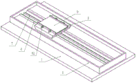
Fig. 1 is a left front corner three-dimensional structure diagram of a chassis frame edge grinding device for computer production.
Fig. 2 is a right rear perspective view perspective structure diagram of a chassis frame edging apparatus for computer production.
Fig. 3 is a left side sectional view of a cabinet frame edging apparatus for computer production.
Fig. 4 is a front sectional view of a cabinet frame edging apparatus for computer production.
Fig. 5 is a top view of a three-dimensional structure of a bottom plate in a case frame edge grinding device for computer production.
Fig. 6 is a bottom view of a three-dimensional structure of a top frame in a case frame edge grinding device for computer production.
Fig. 7 is a partial structure front view of an edging mechanism in a chassis frame edging apparatus for computer production.
Fig. 8 is a side view of a partial structure of an edging mechanism in a chassis frame edging apparatus for computer production.
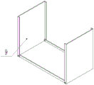
Fig. 9 is a schematic assembly diagram of a chassis frame in a chassis frame edging apparatus for computer production.
In the figure: 1. a base; 2. a support bar; 3. a top frame; 4. a controller; 5. a base plate; 6. a slide rail; 7. a screw; 8. a mobile station; 81. a threaded sleeve; 82. positioning blocks; 9. a chassis frame; 10. a hold-down mechanism; 101. a roller; 102. a first connecting rod; 103. a second connecting rod; 104. an extension plate; 105. a first outer sleeve; 106. a first telescopic rod; 107. a first spring; 108. a compression pad; 109. an electromagnet; 11. an edge grinding mechanism; 111. a hydraulic telescopic outer rod; 112. a hydraulic telescopic inner rod; 113. a grinding wheel; 114. a third connecting rod; 115. a slider; 116. a nut; 117. a blade; 118. a second spring; 12. a fixing mechanism; 121. a second outer sleeve; 122. a second telescopic rod; 123. calibration; 124. a third spring; 125. tightening the knob; 126. fixing the ferrule; 13. a first chute; 14. a second runner.
Detailed Description
The technical solution of the present patent will be described in further detail with reference to the following embodiments.
Referring to fig. 1-9, a chassis frame edge grinding device for computer production comprises a base 1, a top frame 3, a bottom plate 5, a moving table 8, a pressing mechanism 10, an edge grinding mechanism 11 and a fixing mechanism 12, wherein six support rods 2 are fixedly arranged above the base 1, the six support rods 2 are respectively arranged at four corners of the base 1 and at a position which is one third of the total length of the base 1 from left to right, the top end of each support rod 2 is provided with the top frame 3, the middle position of the support rod 2 at the right front end of the base 1 is provided with a controller 4, and the controller 4 can control various elements in the invention; a bottom plate 5 is arranged on the upper surface of the base 1, two mutually parallel slide rails 6 are arranged on the bottom plate 5, the slide rails 6 are arranged from left to right, a groove is arranged between the two slide rails 6, and a screw 7 is arranged in the groove; the top of slide rail 6 is equipped with mobile station 8, and the bottom of mobile station 8 and slide rail 6 contact, and mobile station 8 can move along slide rail 6, has placed quick-witted case frame 9 on the upper surface of mobile station 8.
The top frame 3 is provided with two first sliding grooves 13, the two first sliding grooves 13 are symmetrical front and back, the positions of the first sliding grooves 13 correspond to the two support rods 2 which are positioned at one third of the total length of the base 1, the first sliding grooves 13 are through grooves, the edge grinding mechanisms 11 are hung below the first sliding grooves 13, the bottom ends of the two edge grinding mechanisms 11 correspond to the front side and the back side of the case frame 9, the middle parts of the two edge grinding mechanisms 11 are connected with the fixing mechanisms 12, the opposite ends of the two fixing mechanisms 12 are connected with the middle parts of the edge grinding mechanisms 11, and the ends of the fixing mechanisms 12, which are deviated from each other, are connected with the middle parts of the two support rods 2 which are positioned at one third of the total length of the; the lower surface of the top frame 3 is provided with a second sliding chute 14, the second sliding chute 14 is a non-through chute, and a pressing mechanism 10 is hung below the second sliding chute 14.
A threaded sleeve 81 is fixedly arranged below the mobile station 8, the threaded sleeve 81 is matched with the screw 7, and the screw 7 is rotated to enable the threaded sleeve 81 to drive the mobile station 8 to move left and right along the slide rail 6; the upper surface of the mobile station 8 is provided with a positioning block 82, the position of the positioning block 82 can be adjusted according to the chassis frames 9 with different sizes, and a user can quickly position and place the chassis frames 9 through the positioning block 82.
The pressing mechanism 10 comprises rollers 101, first connecting rods 102, second connecting rods 103, an extending plate 104, first outer sleeves 105, first telescopic rods 106, first springs 107, pressing pads 108 and electromagnets 109, the rollers 101 are arranged inside the second sliding chute 14, the rollers 101 are four in number and are symmetrically arranged in the front and back and left and right directions, the first connecting rods 102 are arranged between the two rollers 101 which are symmetrically arranged in the front and back directions, the first connecting rods 102 are horizontally arranged, and the rollers 101 can rotate around the first connecting rods 102, so that the pressing mechanism 10 can be driven to move left and right along the second sliding chute 14; the lower part of the middle position of the first connecting rod 102 is fixedly connected with the top end of a second connecting rod 103, the second connecting rod 103 is a vertically arranged rod, the bottom end of the second connecting rod 103 is fixedly connected with the upper surface of an extending plate 104, the middle position of the lower surface of the extending plate 104 is fixedly connected with the top end of a first outer sleeve 105, a first telescopic rod 106 is inserted into the first outer sleeve 105, and a first spring 107 is arranged in a gap between the first outer sleeve 105 and the first telescopic rod 106; the bottom of first telescopic link 106 is equipped with compresses tightly pad 108, compresses tightly the inside electro-magnet 109 that is equipped with of pad 108, and the position that compresses tightly pad 108 and quick-witted case frame 9 upper surface contact is equipped with the rubber pad, and when electro-magnet 109 circular telegram, because the mobile station 8 is the cast iron system, first telescopic link 106 can move down and hug closely at the upper surface of mobile station 8 to press from both sides quick-witted case frame 9 tightly, and after electro-magnet 109 outage, first telescopic link 106 can upwards kick-back because the elasticity of first spring 107, removes the clamp to quick-witted case frame 9.
The edge grinding mechanism 11 comprises a hydraulic telescopic outer rod 111, a hydraulic telescopic inner rod 112, a grinding wheel 113, a third connecting rod 114, a sliding block 115, a nut 116, a blade 117 and a second spring 118, the top end of the hydraulic telescopic outer rod 111 is fixedly connected with the bottom end of the third connecting rod 114, the third connecting rod 114 is sleeved with the sliding block 115, the sliding block 115 is arranged in the first sliding groove 13, the sliding block 115 can drive the edge grinding structure 11 to move back and forth along the first sliding groove 13, a rod piece of the third connecting rod 114 above the sliding block 115 is provided with an external thread, the top end of the third connecting rod 114 is sleeved with the nut 116, the nut 116 is matched with the external thread on the third connecting rod 114, the nut 116 is arranged on the upper surface of the top frame 3, the sliding block 115 and the nut 116 can be clamped on the top frame 3 together by tightening the nut 116; a hydraulic telescopic inner rod 112 is inserted into the hydraulic telescopic outer rod 111, a grinding wheel 113 is arranged at the bottom end of the hydraulic telescopic inner rod 112, the grinding wheel 113 is made of diamond, and the working wheel surface of the grinding wheel 113 is in contact with the front side edge and the rear side edge of the chassis frame 9 to grind the front side edge and the rear side edge of the chassis frame 9; the left and right sides of emery wheel 113 all is equipped with blade 117, the top of blade 117 and the bottom fixed connection of the flexible interior pole 112 of hydraulic pressure, the bottom of blade 117 sets up towards the left and right sides slope, blade 117 is total four, two left and right sides symmetry sets up, it is equipped with second spring 118 to lie in between two blades 117 with one side, second spring 118 makes and lies in blade 117 with one side and presss from both sides tightly each other, blade 117 can carry out preliminary clearance to the burr of comparatively dispersion on the side around quick-witted case frame 9, to the burr that is difficult to clear up, two mutual extruded blades 117 can make the burr arrange in order to quick-witted case frame 9 side position directly over, be convenient for edging operation going on afterwards.
The fixing mechanism 12 comprises a second outer sleeve 121, a second telescopic rod 122, scales 123, a third spring 124, a tightening knob 125 and a fixing collar 126, wherein one end of the second outer sleeve 121, which is away from each other, is fixedly arranged on the support rod 2, the inner part of one end of the second outer sleeve 121, which is opposite to each other, is provided with the second telescopic rod 122, the scales 123 are arranged on the second telescopic rod 122, one end of the second telescopic rod 122, which is opposite to each other, is provided with the fixing collar 126, and the fixing collar 126 is sleeved on the outer cylindrical surface of the hydraulic telescopic outer rod 111; the inside third spring 124 that is equipped with of the outer sleeve 121 of second, the outside top of the outer sleeve 121 of second is equipped with tightly decides the knob 125, can be fixed the relative position of second telescopic link 122 with the outer sleeve 121 of second through tightly deciding the knob 125, third spring 124 makes the second telescopic link 122 be convenient for stretch out in the outer sleeve 121 of second, fixed establishment 12 fixes edging mechanism 11, when edging mechanism 11 is when the back-and-forth movement on first spout 13, control second telescopic link 122 extension or shorten, in order to keep the vertical setting state of edging mechanism 11.
Before the edge grinding machine is used, a user firstly adjusts the distance between the positioning blocks 82 according to the size of a case frame 9 to be ground, then adjusts the position of the edge grinding mechanism through the first sliding chute 13 and the nut 116 to enable the edge grinding mechanism to correspond to the front and rear positions of the side edge to be ground of the case frame 9, and then adjusts the grinding wheel 113 to a proper height through the hydraulic telescopic outer rod 111 and the hydraulic telescopic inner rod 112 to enable the grinding wheel 113 to be in contact with the side wall of the case frame 9; when in use, a user places the case frame 9 on the mobile station 8 through the positioning block 82, and the electromagnet 109 is electrified through the controller 4, so that the pressing mechanism 10 presses the case frame 9 on the upper surface of the mobile station 8, when the screw 7 is controlled to rotate by the controller 4, the moving table 8 is moved from right to left, and the grinding wheel 113 is rotated at the same time, during the moving process of the mobile station 8, the grinding wheel 113 will perform the edge grinding operation on the front and rear sides of the chassis frame 9, after the edge grinding of the standby chassis frame 9 is completed, the control screw 7 is reversed, so that the mobile station 8 moves from left to right, in the moving process, the grinding wheel 113 performs the edge grinding operation on the front and rear side edges of the chassis frame 9 again, and after the edge grinding operation is completed, the electromagnet 109 is controlled to be powered off, the pressing mechanism 10 releases the pressing of the chassis frame 9, and the user takes off the chassis frame 9 and performs the same operation on the next chassis frame 9.
In the description of the present invention, it should be noted that the terms "upper", "lower", "front", "rear", "inner", "outer", and the like indicate orientations or positional relationships based on those shown in the drawings, and are only for convenience of description and simplification of description, but do not indicate or imply that the referred device or element must have a specific orientation, be constructed in a specific orientation, and be operated, and thus, should not be construed as limiting the present invention.
In the description of the present invention, it should be noted that, unless otherwise explicitly specified or limited, the terms "mounted," "connected," and "connected" are to be construed broadly, e.g., as meaning either a fixed connection, a removable connection, or an integral connection; can be mechanically or electrically connected; they may be connected directly or indirectly through intervening media, or they may be interconnected between two elements. The specific meaning of the above terms in the present invention can be understood by those of ordinary skill in the art through specific situations.
Although the preferred embodiments of the present patent have been described in detail, the present patent is not limited to the above embodiments, and various changes can be made without departing from the spirit of the present patent within the knowledge of those skilled in the art.
Claims (4)
1. The machine box frame edge grinding equipment for computer production comprises a base (1), a top frame (3), a bottom plate (5), a moving table (8), a pressing mechanism (10), an edge grinding mechanism (11) and a fixing mechanism (12), wherein six support rods (2) are fixedly arranged above the base (1), the top end of each support rod (2) is provided with the top frame (3), and a controller (4) is arranged in the middle of each support rod (2) positioned at the right front end of the base (1); a bottom plate (5) is arranged on the upper surface of the base (1), two sliding rails (6) which are arranged in parallel are arranged on the bottom plate (5), a groove is formed between the two sliding rails (6), and a screw rod (7) is arranged in the groove; a movable table (8) is arranged above the sliding rail (6), the bottom end of the movable table (8) is in contact with the sliding rail (6), and a case frame (9) is placed on the upper surface of the movable table (8); a first sliding groove (13) is formed in the top frame (3);
the edge grinding machine is characterized in that the first sliding grooves (13) are two and symmetrical front and back, the first sliding grooves (13) are through grooves, edge grinding mechanisms (11) are hung below the first sliding grooves (13), the bottom end positions of the two edge grinding mechanisms (11) correspond to the front side edge and the back side edge of a case frame (9), the middle parts of the two edge grinding mechanisms (11) are connected with fixing mechanisms (12), the opposite ends of the two fixing mechanisms (12) are connected with the middle parts of the edge grinding mechanisms (11), and the ends, deviating from each other, of the fixing mechanisms (12) are connected with the middle parts of two support rods (2) positioned at one third of the total length of a base (1); a second sliding chute (14) is formed in the lower surface of the top frame (3), the second sliding chute (14) is a non-through chute, and a pressing mechanism (10) is hung below the second sliding chute (14);
the edge grinding mechanism (11) comprises a hydraulic telescopic outer rod (111), a hydraulic telescopic inner rod (112), a grinding wheel (113), a third connecting rod (114), a sliding block (115), a nut (116), a blade (117) and a second spring (118), the top end of the hydraulic telescopic outer rod (111) is fixedly connected with the bottom end of the third connecting rod (114), the third connecting rod (114) is sleeved with the sliding block (115), the sliding block (115) is arranged in the first sliding groove (13), an external thread is arranged on the rod piece, positioned above the sliding block (115), of the third connecting rod (114), the nut (116) is sleeved at the top end of the third connecting rod (114), the nut (116) is matched with the external thread on the third connecting rod (114), and the nut (116) is arranged on the upper surface of the top frame (3); a hydraulic telescopic inner rod (112) is inserted into the hydraulic telescopic outer rod (111), a grinding wheel (113) is arranged at the bottom end of the hydraulic telescopic inner rod (112), the grinding wheel (113) is made of diamond, and the working wheel surface of the grinding wheel (113) is in contact with the front side edge and the rear side edge of the case frame (9); the left and right sides of emery wheel (113) all is equipped with blade (117), the top of blade (117) and the bottom fixed connection of the flexible interior pole of hydraulic pressure (112), the bottom of blade (117) sets up towards the left and right sides slope, and total four of blade (117), two left and right sides symmetry set up, are located to be equipped with second spring (118) between two blade (117) of same side.
2. The machine box frame edging equipment for computer production according to claim 1, characterized in that a threaded sleeve (81) is fixedly arranged below the moving table (8), and the threaded sleeve (81) is matched with the screw (7); and a positioning block (82) is arranged on the upper surface of the mobile station (8).
3. The chassis frame edging apparatus for computer production according to claim 1, wherein the pressing mechanism (10) comprises rollers (101), first connecting rods (102), second connecting rods (103), an extension plate (104), first outer sleeves (105), first telescopic rods (106), first springs (107), pressing pads (108) and electromagnets (109), the rollers (101) are disposed inside the second sliding grooves (14), the rollers (101) are four in number and are symmetrically disposed front to back and left to right, the first connecting rod (102) is disposed between two rollers (101) symmetrically disposed front to back, and the first connecting rod (102) is a horizontally disposed rod; the lower part of the middle position of the first connecting rod (102) is fixedly connected with the top end of a second connecting rod (103), the second connecting rod (103) is a vertically arranged rod, the bottom end of the second connecting rod (103) is fixedly connected with the upper surface of an extending plate (104), the middle position of the lower surface of the extending plate (104) is fixedly connected with the top end of a first outer sleeve (105), a first telescopic rod (106) is inserted into the first outer sleeve (105), and a first spring (107) is arranged in a gap between the first outer sleeve (105) and the first telescopic rod (106); the bottom end of the first telescopic rod (106) is provided with a pressing pad (108), an electromagnet (109) is arranged inside the pressing pad (108), and a rubber pad is arranged at the position where the pressing pad (108) is in contact with the upper surface of the chassis frame (9).
4. The chassis frame edging device for computer production according to claim 1, wherein the fixing mechanism (12) comprises a second outer sleeve (121), a second telescopic rod (122), scales (123), a third spring (124), a tightening knob (125) and a fixing collar (126), wherein one end of the second outer sleeve (121) which is away from each other is fixedly arranged on the support rod (2), the second telescopic rod (122) is arranged in the opposite end of the second outer sleeve (121), the scales (123) are arranged on the second telescopic rod (122), the fixing collar (126) is arranged at the opposite end of the second telescopic rod (122), and the fixing collar (126) is sleeved on the outer cylindrical surface of the hydraulic telescopic outer rod (111); a third spring (124) is arranged in the second outer sleeve (121), and a fastening knob (125) is arranged above the outer side of the second outer sleeve (121).
Priority Applications (1)
| Application Number | Priority Date | Filing Date | Title |
|---|---|---|---|
| CN201910305682.XA CN109822418B (en) | 2019-04-16 | 2019-04-16 | A quick-witted case frame edging equipment for computer production |
Applications Claiming Priority (1)
| Application Number | Priority Date | Filing Date | Title |
|---|---|---|---|
| CN201910305682.XA CN109822418B (en) | 2019-04-16 | 2019-04-16 | A quick-witted case frame edging equipment for computer production |
Publications (2)
| Publication Number | Publication Date |
|---|---|
| CN109822418A CN109822418A (en) | 2019-05-31 |
| CN109822418B true CN109822418B (en) | 2020-12-15 |
Family
ID=66875584
Family Applications (1)
| Application Number | Title | Priority Date | Filing Date |
|---|---|---|---|
| CN201910305682.XA Active CN109822418B (en) | 2019-04-16 | 2019-04-16 | A quick-witted case frame edging equipment for computer production |
Country Status (1)
| Country | Link |
|---|---|
| CN (1) | CN109822418B (en) |
Families Citing this family (1)
| Publication number | Priority date | Publication date | Assignee | Title |
|---|---|---|---|---|
| CN117532436B (en) * | 2023-12-27 | 2024-06-11 | 重庆强力模具厂 | Welding equipment for automobile power battery pack shell box |
Family Cites Families (8)
| Publication number | Priority date | Publication date | Assignee | Title |
|---|---|---|---|---|
| CA1260717A (en) * | 1984-08-29 | 1989-09-26 | Clarence I. Steinback | Abrasive surfacing machine |
| JP5633487B2 (en) * | 2011-08-30 | 2014-12-03 | 坂東機工株式会社 | Equipment for processing both sides of glass plates |
| CN103111923A (en) * | 2013-03-08 | 2013-05-22 | 格拉斯曼机床(北京)有限公司 | Numerical control irregular glass cutting edging machining center device |
| CN203357186U (en) * | 2013-07-15 | 2013-12-25 | 伍世滔 | Automatic stone edge grinding machine |
| CN107471027A (en) * | 2017-09-02 | 2017-12-15 | 张宇涛 | A kind of computer housing semi-finished product plate edging device |
| CN207358758U (en) * | 2017-09-13 | 2018-05-15 | 贵州传曙科技股份有限公司 | A kind of mobile phone screen edging device |
| CN108788998A (en) * | 2018-07-05 | 2018-11-13 | 浙江新峰包装材料有限公司 | A kind of circle packaging plate production edging device |
| CN108527062A (en) * | 2018-07-16 | 2018-09-14 | 临泉县蓝天钢化玻璃有限公司 | A kind of high strength glass edging device |
-
2019
- 2019-04-16 CN CN201910305682.XA patent/CN109822418B/en active Active
Also Published As
| Publication number | Publication date |
|---|---|
| CN109822418A (en) | 2019-05-31 |
Similar Documents
| Publication | Publication Date | Title |
|---|---|---|
| CN210754641U (en) | Novel adjustable punching device for upper side plate | |
| CN211867536U (en) | Fixing clamp convenient for clamping and used for glass processing | |
| CN211072987U (en) | Adjustable raw material treatment equipment for wood furniture processing | |
| CN109822418B (en) | A quick-witted case frame edging equipment for computer production | |
| CN207397938U (en) | A kind of electromagnetic coil compression tooling | |
| CN108162341B (en) | Automatic plastic handle taking out, punching, cooling and shaping production line | |
| CN213223815U (en) | Stamping part repairing device | |
| CN216127288U (en) | Double-mechanical-arm mechanism for machining automobile parts | |
| CN213163458U (en) | Push-out type direct-line tool changing high-efficiency cutting machine | |
| CN112958843B (en) | Automatic material drawing equipment for workshop machining | |
| CN213106288U (en) | Sofa production is with frock for polishing | |
| CN214134962U (en) | Equipment for cutting die blank | |
| CN210335590U (en) | Window frame right angle clamping and grinding table | |
| CN210678317U (en) | Polishing equipment for processing circular container | |
| CN216442229U (en) | New energy automobile makes and uses spare part processing equipment | |
| CN213319394U (en) | Brake block equipment of polishing | |
| CN219113768U (en) | Grinding and positioning device for PQ type magnetic core | |
| CN217371638U (en) | Stainless steel door production is with equipment of polishing | |
| CN219005557U (en) | Ceramic tile production edging device | |
| CN214313134U (en) | Multilayer chip welding die bonder | |
| CN214351549U (en) | Panel beating grinding device with limit function | |
| CN213136197U (en) | Automatic grinding device of forging | |
| CN214820160U (en) | A remove overlap structure for production of dental lamina working of plastics | |
| CN208543572U (en) | A kind of wood processing machinery auxiliary clamp | |
| CN218427413U (en) | Edging equipment for processing toughened glass |
Legal Events
| Date | Code | Title | Description |
|---|---|---|---|
| PB01 | Publication | ||
| PB01 | Publication | ||
| SE01 | Entry into force of request for substantive examination | ||
| SE01 | Entry into force of request for substantive examination | ||
| GR01 | Patent grant | ||
| GR01 | Patent grant | ||
| TR01 | Transfer of patent right | ||
| TR01 | Transfer of patent right |
Effective date of registration: 20231009 Address after: No. 68 Jiefang Road, Hongning Town Street, Wulian County, Rizhao City, Shandong Province, 262300 Patentee after: Rizhao Yongli Automation Technology Co.,Ltd. Address before: 276800 No.16, Yantai North Road, Donggang District, Rizhao City, Shandong Province Patentee before: RIZHAO POLYTECHNIC |