CN109720552B - Self-balancing surveying and mapping drone - Google Patents
Self-balancing surveying and mapping drone Download PDFInfo
- Publication number
- CN109720552B CN109720552B CN201811647107.XA CN201811647107A CN109720552B CN 109720552 B CN109720552 B CN 109720552B CN 201811647107 A CN201811647107 A CN 201811647107A CN 109720552 B CN109720552 B CN 109720552B
- Authority
- CN
- China
- Prior art keywords
- battery module
- oil tank
- camera
- surveying
- sliding
- Prior art date
- Legal status (The legal status is an assumption and is not a legal conclusion. Google has not performed a legal analysis and makes no representation as to the accuracy of the status listed.)
- Active
Links
Images


Landscapes
- Studio Devices (AREA)
- Feeding And Controlling Fuel (AREA)
Abstract
本发明涉及测绘用无人机设备技术领域,为了解决现有的测绘无人机在使用的过程中,因为油箱的油量减少而重心偏移出现的不平衡,导致测绘工作无法正常进行的问题,提供了一种可自动调节平衡的测绘无人机,包括安装有摄像头的本体,本体包括提供动力的燃油系统,燃油系统包括油箱;其中:本体还包括有安装座,摄像头安装在安装座的一端,油箱位于安装座另一端;本体还设置有安装横杆,安装横杆上滑动连接有电池模块,电池模块与摄像头之间连接有导线,导线设置有螺旋段,螺旋段外套在安装横杆靠近油箱的一端上,电池模块朝向螺旋段的一侧设置有铁制贴片;安装横杆通过弹性件滑动连接有铁制的滑块,滑块远离油箱滑动后插入螺旋段中。
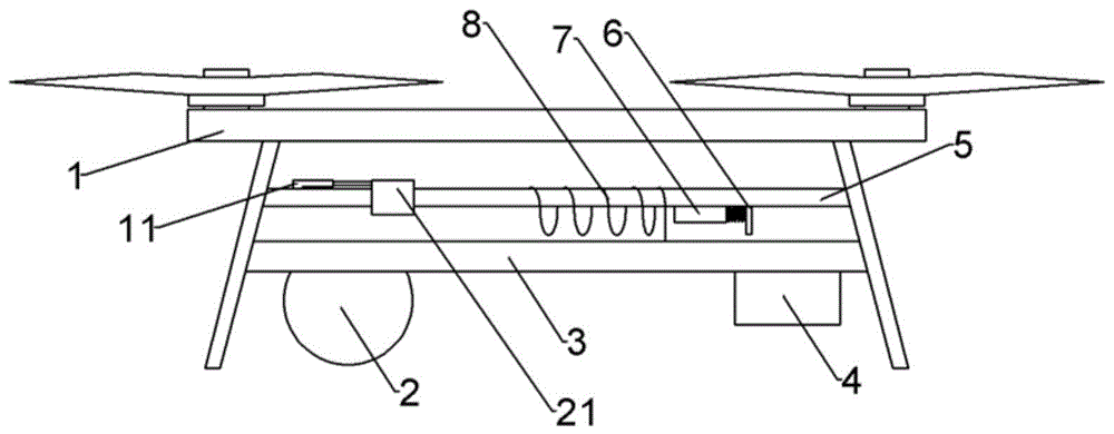
The invention relates to the technical field of unmanned aerial vehicle equipment for surveying and mapping, in order to solve the problem that the surveying and mapping work cannot be carried out normally due to the imbalance of the center of gravity offset due to the reduction of the oil amount of the fuel tank during the use of the existing surveying and mapping unmanned aerial vehicle , provides a surveying and mapping drone that can automatically adjust and balance, including a body mounted with a camera, the body includes a fuel system that provides power, and the fuel system includes a fuel tank; wherein: the body also includes a mounting seat, and the camera is installed on the mounting seat. At one end, the fuel tank is located at the other end of the mounting seat; the body is also provided with a mounting crossbar, on which a battery module is slidably connected, a wire is connected between the battery module and the camera, and the wire is provided with a spiral section, and the spiral section covers the mounting crossbar On one end close to the fuel tank, the side of the battery module facing the helical segment is provided with an iron patch; the installation crossbar is slidably connected to an iron slider through an elastic member, and the slider is inserted into the helical segment after sliding away from the fuel tank.
Description
Claims (7)
Priority Applications (1)
| Application Number | Priority Date | Filing Date | Title |
|---|---|---|---|
| CN201811647107.XA CN109720552B (en) | 2018-12-29 | 2018-12-29 | Self-balancing surveying and mapping drone |
Applications Claiming Priority (1)
| Application Number | Priority Date | Filing Date | Title |
|---|---|---|---|
| CN201811647107.XA CN109720552B (en) | 2018-12-29 | 2018-12-29 | Self-balancing surveying and mapping drone |
Publications (2)
| Publication Number | Publication Date |
|---|---|
| CN109720552A CN109720552A (en) | 2019-05-07 |
| CN109720552B true CN109720552B (en) | 2021-04-23 |
Family
ID=66298675
Family Applications (1)
| Application Number | Title | Priority Date | Filing Date |
|---|---|---|---|
| CN201811647107.XA Active CN109720552B (en) | 2018-12-29 | 2018-12-29 | Self-balancing surveying and mapping drone |
Country Status (1)
| Country | Link |
|---|---|
| CN (1) | CN109720552B (en) |
Families Citing this family (4)
| Publication number | Priority date | Publication date | Assignee | Title |
|---|---|---|---|---|
| CN112682636B (en) * | 2020-12-18 | 2022-06-21 | 重庆工程职业技术学院 | Asset management workstation |
| CN113306703B (en) * | 2021-07-20 | 2023-07-18 | 武汉航测空间信息技术有限公司 | Surveying and mapping unmanned aerial vehicle capable of automatically adjusting balance |
| CN113746033B (en) * | 2021-09-07 | 2022-11-01 | 浙江启明电力集团有限公司 | A bury underground plough mechanism for submarine cable lays |
| KR102842354B1 (en) * | 2023-02-27 | 2025-08-04 | 정규영 | Battery attachment device for drones |
Family Cites Families (6)
| Publication number | Priority date | Publication date | Assignee | Title |
|---|---|---|---|---|
| CN106828886A (en) * | 2017-01-16 | 2017-06-13 | 北京猎鹰无人机科技有限公司 | A kind of aircraft center of gravity dynamically balancing device |
| CN207482182U (en) * | 2017-10-19 | 2018-06-12 | 王鹏 | A kind of regulating device of unmanned plane center of gravity |
| CN108341046B (en) * | 2018-01-18 | 2021-11-30 | 广西电网有限责任公司梧州供电局 | Aerial position adjusting device of unmanned aerial vehicle |
| CN207931979U (en) * | 2018-01-30 | 2018-10-02 | 成都睿铂科技有限责任公司 | A kind of unmanned plane balance mechanism |
| CN108639344B (en) * | 2018-06-27 | 2020-05-01 | 江苏空神航空工业有限公司 | A well-balanced drone |
| CN112437740B (en) * | 2018-07-12 | 2024-03-08 | 索尼公司 | Unmanned aerial vehicles, actuation methods and procedures |
-
2018
- 2018-12-29 CN CN201811647107.XA patent/CN109720552B/en active Active
Also Published As
| Publication number | Publication date |
|---|---|
| CN109720552A (en) | 2019-05-07 |
Similar Documents
| Publication | Publication Date | Title |
|---|---|---|
| CN109720552B (en) | Self-balancing surveying and mapping drone | |
| US9094089B2 (en) | Gimbaled mount system for satellites | |
| CN109278962A (en) | A cableless submarine observation platform suitable for the whole ocean depth | |
| CN111891374A (en) | A kind of unmanned aerial vehicle field endurance system and method thereof | |
| AU2015257473B2 (en) | Offshore structure with self-install, self-level and self-pile capabilities | |
| CN217496535U (en) | Reservoir area pollution sources reconnaissance triphibian unmanned aerial vehicle | |
| CN204937522U (en) | A kind of unmanned plane The Cloud Terrace and unmanned plane | |
| CN216546771U (en) | Unmanned aerial vehicle's descending platform for survey and drawing data acquisition | |
| CN213948761U (en) | Amphibious unmanned aerial vehicle with cloud platform | |
| CN217456372U (en) | Unmanned aerial vehicle aerial photography survey and drawing balancing unit | |
| CN206059621U (en) | A kind of unmanned plane gps antenna can folding and unfolding mounting structure | |
| CN214986069U (en) | Unmanned aerial vehicle remote sensing formation of image unmanned aerial vehicle that takes photo by plane | |
| US4414511A (en) | Low resistance, fluid replenishing, reference cell and method for using same in structure-to-soil electrical surveys | |
| CN204137327U (en) | The Micro Aerial Vehicle of a kind of quick shooting compare rule orthogonal projection figure | |
| CN113386944B (en) | Unmanned aerial vehicle based on sensor POS and IMU coupler | |
| CN220263128U (en) | Folding type air-sea dual-purpose unmanned aerial vehicle | |
| CN117048825A (en) | Automatic air-drop arrangement device of underwater glider | |
| JP3231880U (en) | Multi-layer anti-aircraft sign | |
| CN213109787U (en) | Unmanned aerial vehicle plotter balancing unit | |
| CN214649092U (en) | Aircraft with aviation structure | |
| CN210063384U (en) | Install convenient light-duty five camera lens mapping camera systems of unmanned aerial vehicle | |
| CN211055326U (en) | AUV cluster surface of water cloth puts device | |
| CN223751148U (en) | A vehicle-mounted drone take-off and landing platform | |
| CN218055661U (en) | Power supply device for photovoltaic intelligent inspection unmanned aerial vehicle | |
| CN222005420U (en) | A drone for surveying and mapping |
Legal Events
| Date | Code | Title | Description |
|---|---|---|---|
| PB01 | Publication | ||
| PB01 | Publication | ||
| SE01 | Entry into force of request for substantive examination | ||
| SE01 | Entry into force of request for substantive examination | ||
| GR01 | Patent grant | ||
| GR01 | Patent grant | ||
| EE01 | Entry into force of recordation of patent licensing contract |
Application publication date: 20190507 Assignee: Chongqing Songqing Engineering Technology Consulting Co.,Ltd. Assignor: CHONGQING VOCATIONAL INSTITUTE OF ENGINEERING Contract record no.: X2024980019352 Denomination of invention: Surveying drone with automatic balance adjustment Granted publication date: 20210423 License type: Common License Record date: 20241030 |
|
| EE01 | Entry into force of recordation of patent licensing contract | ||
| EE01 | Entry into force of recordation of patent licensing contract |
Application publication date: 20190507 Assignee: Blue Butterfly (Chongqing) Technology Development Co.,Ltd. Assignor: CHONGQING VOCATIONAL INSTITUTE OF ENGINEERING Contract record no.: X2024980020180 Denomination of invention: Surveying drone with automatic balance adjustment Granted publication date: 20210423 License type: Common License Record date: 20241108 |
|
| EE01 | Entry into force of recordation of patent licensing contract | ||
| EE01 | Entry into force of recordation of patent licensing contract |
Application publication date: 20190507 Assignee: Zhongyixin Evergrande Data Research Institute (Chongqing) Co.,Ltd. Assignor: CHONGQING VOCATIONAL INSTITUTE OF ENGINEERING Contract record no.: X2024980021319 Denomination of invention: Surveying drone with automatic balance adjustment Granted publication date: 20210423 License type: Common License Record date: 20241118 |
|
| EE01 | Entry into force of recordation of patent licensing contract | ||
| EE01 | Entry into force of recordation of patent licensing contract |
Application publication date: 20190507 Assignee: CHONGQING 5A TECHNOLOGY Co.,Ltd. Assignor: CHONGQING VOCATIONAL INSTITUTE OF ENGINEERING Contract record no.: X2024980032671 Denomination of invention: Surveying drone with automatic balance adjustment Granted publication date: 20210423 License type: Common License Record date: 20241204 Application publication date: 20190507 Assignee: Zhonglan Certification Co.,Ltd. Assignor: CHONGQING VOCATIONAL INSTITUTE OF ENGINEERING Contract record no.: X2024980032656 Denomination of invention: Surveying drone with automatic balance adjustment Granted publication date: 20210423 License type: Common License Record date: 20241204 |
|
| EE01 | Entry into force of recordation of patent licensing contract | ||
| EE01 | Entry into force of recordation of patent licensing contract |
Application publication date: 20190507 Assignee: Jinsuiyuan (Chongqing) Technology Co.,Ltd. Assignor: CHONGQING VOCATIONAL INSTITUTE OF ENGINEERING Contract record no.: X2024980033079 Denomination of invention: Surveying drone with automatic balance adjustment Granted publication date: 20210423 License type: Common License Record date: 20241210 Application publication date: 20190507 Assignee: Chongqing bitshutu Technology Co.,Ltd. Assignor: CHONGQING VOCATIONAL INSTITUTE OF ENGINEERING Contract record no.: X2024980033167 Denomination of invention: Surveying drone with automatic balance adjustment Granted publication date: 20210423 License type: Common License Record date: 20241212 |
|
| EE01 | Entry into force of recordation of patent licensing contract | ||
| EE01 | Entry into force of recordation of patent licensing contract |
Application publication date: 20190507 Assignee: Chongqing Xianchen Technology Co.,Ltd. Assignor: CHONGQING VOCATIONAL INSTITUTE OF ENGINEERING Contract record no.: X2024980036450 Denomination of invention: Surveying drone with automatic balance adjustment Granted publication date: 20210423 License type: Common License Record date: 20241213 Application publication date: 20190507 Assignee: Chongqing Runsan Technology Co.,Ltd. Assignor: CHONGQING VOCATIONAL INSTITUTE OF ENGINEERING Contract record no.: X2024980036308 Denomination of invention: Surveying drone with automatic balance adjustment Granted publication date: 20210423 License type: Common License Record date: 20241213 |
|
| EE01 | Entry into force of recordation of patent licensing contract | ||
| EE01 | Entry into force of recordation of patent licensing contract |
Application publication date: 20190507 Assignee: Chongqing Fengxiansen Cultural and Creative Co.,Ltd. Assignor: CHONGQING VOCATIONAL INSTITUTE OF ENGINEERING Contract record no.: X2024980037475 Denomination of invention: Surveying drone with automatic balance adjustment Granted publication date: 20210423 License type: Common License Record date: 20250206 |
|
| EE01 | Entry into force of recordation of patent licensing contract |