CN109641663B - Deicing module for an aircraft and method for deicing - Google Patents
Deicing module for an aircraft and method for deicing Download PDFInfo
- Publication number
- CN109641663B CN109641663B CN201780055305.4A CN201780055305A CN109641663B CN 109641663 B CN109641663 B CN 109641663B CN 201780055305 A CN201780055305 A CN 201780055305A CN 109641663 B CN109641663 B CN 109641663B
- Authority
- CN
- China
- Prior art keywords
- movable
- aircraft
- wing
- shell
- module
- Prior art date
- Legal status (The legal status is an assumption and is not a legal conclusion. Google has not performed a legal analysis and makes no representation as to the accuracy of the status listed.)
- Active
Links
Images


Classifications
-
- B—PERFORMING OPERATIONS; TRANSPORTING
- B64—AIRCRAFT; AVIATION; COSMONAUTICS
- B64D—EQUIPMENT FOR FITTING IN OR TO AIRCRAFT; FLIGHT SUITS; PARACHUTES; ARRANGEMENT OR MOUNTING OF POWER PLANTS OR PROPULSION TRANSMISSIONS IN AIRCRAFT
- B64D15/00—De-icing or preventing icing on exterior surfaces of aircraft
- B64D15/16—De-icing or preventing icing on exterior surfaces of aircraft by mechanical means, e.g. pulsating mats or shoes attached to, or built into, surface
-
- B—PERFORMING OPERATIONS; TRANSPORTING
- B64—AIRCRAFT; AVIATION; COSMONAUTICS
- B64C—AEROPLANES; HELICOPTERS
- B64C3/00—Wings
- B64C3/26—Construction, shape, or attachment of separate skins, e.g. panels
Landscapes
- Engineering & Computer Science (AREA)
- Mechanical Engineering (AREA)
- Aviation & Aerospace Engineering (AREA)
- Structures Of Non-Positive Displacement Pumps (AREA)
Abstract
一种用于对冰积聚于其上、例如飞行器机翼上的表面(66)除冰的设备和方法。用于除冰模块的设备和方法包括促动构件、壳(28)和可移动部件(36)。可移动部件打破已积聚在机翼的表面上的冰。

An apparatus and method for deicing a surface (66) on which ice accumulates, such as on an aircraft wing. An apparatus and method for a de-icing module includes an actuating member, a housing (28), and a moveable component (36). The movable parts break up ice that has accumulated on the surface of the wing.
Description
Background
Contemporary turboprop aircraft include wings having surfaces that may be prone to ice accumulation under certain flight conditions. Aircraft approved for flight into known icing conditions must include provisions to prevent unacceptable levels of ice build-up on the wings. Ice build-up on the wing affects the aerodynamic efficiency of the wing. The amount of ice build-up or accumulation is limited to high aerodynamic efficiency.
Conventional aircraft may include electrical or pneumatic heating systems to provide cyclic or continuous heating of the aerodynamic surfaces and/or propeller blades to control the accumulation, or shedding of ice. Conventional aircraft may also use inflated rubber membranes (commonly referred to as "sleeves") that are inflated cyclically with air pressure. This approach is limited to slower moving aircraft due to increased aerodynamic drag losses. Another approach is a set of electromagnetic or piezoelectric actuators mounted below the protected surface and operated cyclically at high frequency to break the ice. Another common approach for small general aviation aircraft and Unmanned Aerial Vehicles (UAVs) is to pump de-icing fluid and deliver it to the protected area via spray nozzles or through drain holes.
Brief description of the invention
In one aspect, the present disclosure relates to a deicing module for an aircraft with: a shell operably coupled to an aircraft surface; at least one movable component located between the shell and the aircraft surface; a drive mechanism operably coupled to the at least one movable component and configured to move the at least one movable component under the shell such that the at least one movable component deforms the shell to a degree sufficient to release ice accumulated thereon.
In another aspect, the present disclosure is directed to an aircraft wing comprising: a set of ribs defining a depth and a shape of an airfoil of an aircraft wing, wherein the airfoil includes a leading edge, an upper surface, a lower surface, and a trailing edge spaced from the leading edge; at least one spar interconnecting the sets of ribs; at least one skin covering at least a portion of the airfoil; and a de-icing mechanism comprising a shell covering at least a portion of the leading edge, at least one movable component located between the shell and the aircraft surface, a drive mechanism operably coupled to the at least one movable component and configured to move the at least one movable component beneath the shell such that the at least one movable component deforms the shell to an extent sufficient to release ice accumulated thereon.
In yet another aspect, the present disclosure is directed to a method for deicing a surface on which ice accumulates, the method comprising moving at least one movable member below the surface such that the at least one movable member deforms the surface to an extent sufficient to release ice accumulated thereon, and wherein the at least one movable member is moved below the surface to sequentially release ice accumulated thereon.
Brief description of the drawings
In the drawings:
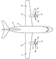
fig. 1 illustrates an exemplary schematic top view of an aircraft having wings and propellers according to various aspects described herein.
FIG. 2 is a perspective view of a wing according to various aspects described herein, and the wing may be included in the aircraft of FIG. 1.
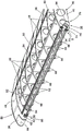
Fig. 3 is a perspective view of the wing of fig. 2 with a top surface removed in accordance with various aspects described herein.
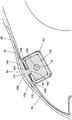
FIG. 4 is an enlarged view of one end of the airfoil of FIG. 2 in accordance with various aspects described herein.
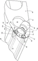
Fig. 5 is an enlarged view of a second end of the airfoil of fig. 2 in accordance with various aspects described herein.
Fig. 6 is a cross-section of a front portion of the wing of fig. 2, according to various aspects described herein.
Fig. 7 is a cross-section of an additional embodiment of a front portion of the wing of fig. 2, according to various aspects described herein.
Description of embodiments of the invention
Various aspects described herein relate to preventing or reducing ice build-up, accumulation, or shedding on aircraft wings. Embodiments of the present disclosure may be implemented in any environment, device, or method for preventing or reducing ice on a surface, regardless of the function performed by the surface. By way of non-limiting example, such a surface is a surface of a wing of an aircraft, wherein the aircraft may have a turboprop or turbofan jet engine or any other suitable engine for an aircraft. The remainder of this application is therefore directed to such an environment.
As used herein, the terms "forward" or "upstream" refer to moving in a direction toward the engine inlet, or a component being relatively closer to the engine inlet than another component. The terms "aft" or "downstream" used in connection with "forward" or "upstream" refer to a direction toward the rear or outlet of the engine, or relatively closer to the engine outlet than another component.
Further, as used herein, the term "spanwise" refers to a dimension along the length of the wing, and "chordwise" refers to a dimension along the width of the wing.
Further, as used herein, the terms "radial" or "radially" refer to a dimension extending between a central longitudinal axis of the engine and an outer periphery of the engine.
All directional references (e.g., radial, axial, proximal, distal, upper, lower, upward, downward, left, right, lateral, forward, rearward, top, bottom, above, below, vertical, horizontal, clockwise, counterclockwise, upstream, downstream, forward, rearward, etc.) are only used for identification purposes to aid the reader's understanding of the present invention, and do not create limitations, particularly as to the position, orientation, or use of the invention. Joinder references (e.g., attached, coupled, connected, and joined) are to be construed broadly and may include intermediate members between a series of elements and relative movement between elements unless otherwise indicated. Thus, connected references do not necessarily imply that two elements are directly connected and in a fixed relationship to each other. The exemplary drawings are for illustrative purposes only and the dimensions, positions, order, and relative sizes reflected in the drawings attached hereto may vary.
Fig. 1 depicts an aircraft 10 having a fuselage 12 and wings 14 extending outwardly from the fuselage 12. The aircraft 10 may include at least one turboprop engine 16 coupled to the aircraft 10, shown as a set of engines 16 coupled with opposing wings 14. The turboprop engine 16 may include a set of propeller blades 18 coupled with the engine 16 at a rotatable hub assembly 19 such that the engine 16 drives rotation 22 of the propeller about an axis of rotation 20.
Although an aircraft 10 having two turboprop engines 16 has been illustrated, embodiments of the present disclosure may include any number of engines 16 or propeller blades 18, or any arrangement of engines 16 or blades 18 relative to the aircraft. Additionally, the rotation 22 of the propeller blades 18 is provided for understanding embodiments of the present disclosure. Embodiments of the present disclosure may include alternative directions of rotation 22 of the propeller blades 18, or embodiments in which the set of turboprop engines 16 rotate the propeller blades 18 in the same or opposite directions.
Fig. 2 depicts an enlarged perspective view of an exemplary portion of one of the wings 14, including an airfoil 40 having a leading edge 42 and a trailing edge 44. The leading edge 42 may provide torsional stiffness while the trailing edge 44 may be flexible, rigid, or a combination of both. The set of ribs 46 define the depth and shape of the airfoil 40. A skin 48 covers at least a portion of the airfoil 40 and includes an upper surface 50 and a lower surface 52 that extend from the leading edge 42 to the trailing edge 44 to define an interior 54. The interior 54 extends spanwise from a root section 56 of the wing 14 to a tip section 58 of the wing 14. At least one spar 60 interconnects the sets of ribs 46 and extends spanwise within the interior 54. The wing 14 may be formed from carbon fiber, aluminum alloy, titanium, or any suitable combination of materials.
A de-icing module 26 is also shown, and the de-icing module 26 includes a housing 28, a drive mechanism 30, and at least one movable member 34. Deicing module 26 may be mounted or otherwise attached to wing 14 at leading edge 42. For example, the set of rails 82 are mounted to the set of ribs 46 (FIG. 3) and are located in the interior 54 of the wing 14. Other attachment assemblies are contemplated having mounting features including magnets, curved tracks, ball bearings, sets of rails, and the like. In the example shown, the rails are inserted into the set of ribs 46 such that the airfoil shape of the wing 14 is not substantially changed.
The shell 28 may be a flexible shell 28 covering the skin 48, including at least a portion of the leading edge 42 or the entire leading edge 42. The compliant shell 28 may extend chordwise from the leading edge 42 of the airfoil 40 to the upper surface 50 of the airfoil 40. It is contemplated that the flexible shell may also extend from the leading edge 42 to the lower surface 52 or any other suitable location. The flexible cover 28 may be a rubber pad 62 made of, for example (although not limited to), neoprene or any suitable elastomeric material. It is also contemplated that the material may be a metallic material having fatigue and strength limits within the flexibility constraints. The flexible cover 28 includes a surface 66 on which ice can accumulate on the surface 66.
The drive mechanism 30 may be located, for example, but not limited to, at the root 56 of the wing 14, and may include, for example, although not limited to, a rotary actuator 64. The drive mechanism 30 also includes, for example and without limitation, a cable system 72 as shown. Other systems are also contemplated including, but not limited to, chain, belt, or screw drive systems or combinations of all or portions of such systems. The cable system 72 includes a cable 74, a motor 76, and a pulley 78. The cable system 72 may be, for example, a jack screw, or any other suitable mechanism capable of lateral movement along the leading edge 42 of the wing 14.
Turning to fig. 3, the skin 48 and flexible skin 28 of the wing have been cut away to reveal sets of ribs 46 having grooves 88 through which the sets of rails 82 may extend.
The cable 74 is wrapped around the pulley 78 and coupled to the at least one movable member 34. The cables 74 extend into a set of tracks 82. The set of tracks are recessed into rib 46 and may include channels 80 having an exemplary rectangular cross-section. The movable member 34 is disposed along an outer surface 84 of the set of tracks 82 and is disposed below the flexible cover 28 at a starting location 86 near one of the root 56 or tip 58 of the wing.
The set of tracks 82 may include a first track 90 positioned along the leading edge 42 and a second track 92 positioned along the upper surface 50 of the airfoil 40. Although two tracks 82 are depicted, it should be understood that the wing 14 may include one or more tracks 82.
Fig. 4 is an enlarged view of the movable component 34 at a starting position 86 near the tip 58 of the wing 14. Portions of the flexible skin 28 have been cut away along with the skin 48 of the wing 14.
The at least one movable member 34 may include any number of members, including a plurality of movable members. The two moving parts are shown as a first movable part 34 and a second movable part 36. The movable member 34 includes a base 100, the base 100 being shown as (but not limited to) a square, that faces the outer surface 84 of the first track 90. At the middle 102 of the base 100, the movable member 34 is coupled to the cable 74. A curved face 104 extends from the base and terminates in a tip 106, wherein the movable member 34 is configured to abut the flexible shell 28. The base 100 may be any suitable shape, such as, but not limited to, circular, square, or angular, that conforms to the shape of any suitable corresponding track 82.
FIG. 5 is an enlarged view of the root 56 of the airfoil 14 with the rotary actuator 64 coupled to the rib 46. The flexible shell 28 is shown in place and includes a deformed portion 108 where the movable member 34 abuts the flexible shell 28. The first and second tracks 90, 92 are shown as being substantially rectangular and having facing sides 110 that define a gap 112.
Turning to FIG. 6, a cross-section of the movable member 34 includes the curved face 104 and the tip 106, which together form an upper portion 114 of the movable member 34 configured to abut the flexible cover 28. The movable member 34 is contoured to the wing 14 to maintain aerodynamic integrity without reducing efficiency. The upper portion 114 includes a thin profile 116 that conforms to the upper surface 50 of the airfoil 40.
At the middle 102 of the movable member 34, the upper portion 114 is coupled to a lower portion 118, the lower portion 118 being formed in any shape that can be received within the track 82. Cable 74 passes through and is operably coupled to middle section 120 of lower portion 118.
Although shown as being disposed along the outer surface 84 of the set of tracks 82 and below the flexible cover 28, it is understood that the movable member 34 may be disposed in any suitable manner so as not to bind or distort when in operation.
Although the movable member is characterized as having a curved face terminating in a tip, it will be understood that the shape of the movable member may vary. The movable member may also be a ball operably coupled to the set of tracks. It should be further understood that although depicted on a wing of an aircraft, the de-icing module may be implemented in other areas of the aircraft, such as, but not limited to, a nacelle, or on other devices (such as, but not limited to, wind engines, propellers, tail sections, stabilizers, flaps).
In operation, the rotary actuator 64 may be actuated when the pilot of the aircraft opens the de-icing arrangement in the event that ice has accumulated on the wing 14. The rotary actuator 64 will rotate, turning the pulley 78 and in turn providing lateral movement of the cable within the set of tracks 82. The set of tracks 82 is configured to guide the two movable components 34, 36 laterally in opposite directions along the length of the wing 14 while deforming the flexible shell 28. The position of the movable components 34, 36 in a position relative to each other allows any imbalance that may occur on the wing 14 to be minimized. When each of the movable members 34, 36 reaches the opposite end of the track 82 from their starting positions 86, a switch (not shown) is provided to reverse the motor 76 and return the movable members 34, 36 to their respective starting positions 86. It is also contemplated that each movable member 34, 36 may remain at the opposite end of the track 82 until another de-icing operation is actuated. The deformation of the flexible shell 28 may break the ice that has accumulated on the surface 66. It is also contemplated that the movable members 34, 36 may be automatically moved upon receiving a signal of ice detection on the wing.
Deicing module 126 is contemplated in fig. 7 as being similar to deicing module 26 and therefore like parts will be identified with like numerals increased by 100. It is to be understood that the description of similar parts of deicing module 26 applies to deicing module 126, unless otherwise specified.
The de-icing module 126 may include a rotation system 172 having a movable member 134, the movable member 134 being, by way of non-limiting example, a ball 132, wherein the ball 132 is configured to continuously move laterally along the leading edge 142 of the airfoil 114. The rotation system 172 includes a cable 174, the cable 174 extending through the balls 134 and configured to continuously rotate such that the balls 132 slide along the set of tracks 182. The rotational system 172 may include rolling element bearings 170 to keep frictional losses low.
A method for deicing a surface 66 on which ice accumulates may include moving at least one movable member 34 below the surface 66 such that the at least one movable member 34 deforms the surface 66. The surface is deformed to an extent sufficient to release any accumulation of ice on the surface 66. Sufficient deformation may be between 1/8 inches and 1/2 inches, or on the order of magnitude of the deformation of a pneumatic sleeve of less than about 1 inch.
The at least one movable member 34 may be moved to adjacent portions of the surface 66 to sequentially release the accumulated ice. It is further contemplated that upon moving the movable member 34 to an adjacent portion of the surface 66, ice is released from the surface and thus removed. The release of ice is due to breaking of ice that has accumulated, or preventing complete formation of ice that has begun the process of formation.
For example, the movement may be (although not limited to) a lateral movement along the length of the surface as shown herein, or a circular movement under a portion of the surface, or a sinusoidal movement, or any suitable movement for deforming the surface to release accumulated ice.
The method may also include actuating a driver operably coupled to the at least one movable component. The drive may be any drive mechanism, such as the rotary actuator 64 described herein.
Historically, wing de-icing has presented a continuing challenge to the aerospace industry. Current deicing techniques typically require: bleed air to heat the wing, which reduces engine efficiency and increases fuel consumption; ethylene glycol, which wets the wing, includes extra weight and has a limited duration; an electric heater, which requires significant power and again reduces engine efficiency; electrical repulsion, which relies on mechanical vibration methods that may have acoustically uncomfortable effects and may increase structural stresses on the surface and the gantry; and a sleeve inflation system, which must remain air tight and add additional weight. Bushings also create significant aerodynamic drag and are generally limited to slower propeller driven aircraft. These current techniques may reduce efficiency, increase power usage, increase weight, and require higher maintenance. The methods contemplated herein overcome these problems by providing a low power method of mechanically removing accumulated ice.
Advantages to the de-icing module described herein include low weight to the actuation and drive assembly (where additional liquid storage on the aircraft is not required). The mechanical stroke of the movable part requires low power usage because of the low duty cycle (once every few minutes of operation, and it does not have to provide enough energy to melt the ice and evaporate the water (like thermal ice protection)). Eliminating the need for bleed air to heat the wing surface or inflate and deflate rubber bushings improves the efficiency of the engine and allows the bleed air to be used elsewhere. The smooth lateral movement of the deicing module is acoustically quiet and significantly reduces the number of repeated stress cycles to the protected surface compared to electrically repulsive ice protection systems.
Commercial advantages include a high level of technical readiness for the various components, resulting in low development and material costs. Improving fuel efficiency during flight reduces operating costs. Another benefit includes improved maintenance over current bushing-based de-icing systems because the flexible shells described herein do not require air-tight seals.
To the extent not already described, the various features and structures of the various embodiments may be used in combination with one another as desired. A feature may not be shown in all embodiments and is not intended to be construed as though it may not be, but is done so for brevity of description. Thus, the various features of the different embodiments can be mixed and matched as desired to form new embodiments, whether or not such new embodiments are explicitly described. Further, while various elements have been described as being "grouped," it will be understood that "grouped" may include any number of the respective elements, including only one element. Combinations or permutations of features described herein are covered by this disclosure. Further, it will be understood that many other possible embodiments and configurations other than those shown in the above figures are contemplated by the present disclosure.
This written description uses examples to disclose embodiments of the invention, including the best mode, and also to enable any person skilled in the art to practice embodiments of the invention, including making and using any devices or systems and performing any incorporated methods. The patentable scope of the invention is defined by the claims, and may include other examples that occur to those skilled in the art. Such other examples are intended to be within the scope of the claims if they have structural elements that do not differ from the literal language of the claims, or if they include equivalent structural elements with insubstantial differences from the literal languages of the claims.
Claims (14)
Applications Claiming Priority (3)
| Application Number | Priority Date | Filing Date | Title |
|---|---|---|---|
| US15/259599 | 2016-09-08 | ||
| US15/259,599 US10273012B2 (en) | 2016-09-08 | 2016-09-08 | Deicing module for an aircraft and method for deicing |
| PCT/US2017/047926 WO2018048615A1 (en) | 2016-09-08 | 2017-08-22 | Deicing module for an aircraft and method for deicing |
Publications (2)
| Publication Number | Publication Date |
|---|---|
| CN109641663A CN109641663A (en) | 2019-04-16 |
| CN109641663B true CN109641663B (en) | 2022-05-24 |
Family
ID=59772724
Family Applications (1)
| Application Number | Title | Priority Date | Filing Date |
|---|---|---|---|
| CN201780055305.4A Active CN109641663B (en) | 2016-09-08 | 2017-08-22 | Deicing module for an aircraft and method for deicing |
Country Status (6)
| Country | Link |
|---|---|
| US (1) | US10273012B2 (en) |
| EP (1) | EP3509950B1 (en) |
| JP (1) | JP2019529213A (en) |
| CN (1) | CN109641663B (en) |
| CA (1) | CA3035609A1 (en) |
| WO (1) | WO2018048615A1 (en) |
Families Citing this family (14)
| Publication number | Priority date | Publication date | Assignee | Title |
|---|---|---|---|---|
| US10888051B2 (en) * | 2017-04-11 | 2021-01-12 | Thomas Peter DeFelice | Intelligent systems for weather modification programs |
| CN109808897B (en) * | 2018-12-19 | 2020-07-28 | 山东大学 | Deicing device and method for elastic belt for wing |
| JP7348774B2 (en) * | 2019-08-28 | 2023-09-21 | 株式会社Subaru | electric aircraft |
| CN111452951B (en) * | 2020-04-14 | 2022-01-14 | 山东大学 | Wing deicer and wing comprising same |
| JP7545231B2 (en) * | 2020-05-23 | 2024-09-04 | 雅文 山崎 | A multicopter equipped with a de-icing device that sprays a freezing point depressant |
| US11294401B2 (en) | 2020-07-08 | 2022-04-05 | Saudi Arabian Oil Company | Flow management systems and related methods for oil and gas applications |
| US11314266B2 (en) | 2020-07-08 | 2022-04-26 | Saudi Arabian Oil Company | Flow management systems and related methods for oil and gas applications |
| US11802645B2 (en) | 2020-07-08 | 2023-10-31 | Saudi Arabian Oil Company | Flow management systems and related methods for oil and gas applications |
| US11274501B2 (en) | 2020-07-08 | 2022-03-15 | Saudi Arabian Oil Company | Flow management systems and related methods for oil and gas applications |
| US11256273B2 (en) | 2020-07-08 | 2022-02-22 | Saudi Arabian Oil Company | Flow management systems and related methods for oil and gas applications |
| US11131158B1 (en) | 2020-07-08 | 2021-09-28 | Saudi Arabian Oil Company | Flow management systems and related methods for oil and gas applications |
| FR3120052A1 (en) * | 2021-02-23 | 2022-08-26 | Edmond Thuries | Airplane wings with mechanical de-icing system |
| CN112550665B (en) * | 2021-02-24 | 2021-04-30 | 中国空气动力研究与发展中心低速空气动力研究所 | Aircraft defroster based on elastic skin |
| US20240389523A1 (en) * | 2023-05-23 | 2024-11-28 | Toyota Motor Engineering & Manufacturing North America, Inc. | Weather management system |
Citations (9)
| Publication number | Priority date | Publication date | Assignee | Title |
|---|---|---|---|---|
| DE652020C (en) * | 1937-10-23 | Continental Gummi Werke Akt Ge | Device for splitting off the ice accumulation on airplane wings | |
| FR832205A (en) * | 1938-01-18 | 1938-09-23 | Device for preventing the accumulation of ice on the leading edges of aircraft wings and the like | |
| DE699463C (en) * | 1937-08-10 | 1940-11-29 | Guenther Heydt Dr Ing | Device for removing ice layers from aircraft parts |
| GB541268A (en) * | 1940-05-14 | 1941-11-20 | Richard Hays Burgess | De-icing mechanism for aircraft |
| EP0036875A1 (en) * | 1979-10-03 | 1981-10-07 | The B.F. GOODRICH Company | Composite leading edge for aircraft |
| CA2088949A1 (en) * | 1992-02-07 | 1993-08-08 | Richard Lawrence Rauckhorst | Airfoil with integral de-icer using overlapped tubes |
| CA2713579A1 (en) * | 2008-02-04 | 2009-08-13 | Airbus Operations Gmbh | Engine intake flap for being arranged on the housing of an air intake of an aircraft engine, as well as engine with such an engine intake flap and aircraft system |
| EP2474473A1 (en) * | 2011-01-11 | 2012-07-11 | BAE Systems PLC | Turboprop-powered aircraft |
| CN105416593A (en) * | 2015-12-11 | 2016-03-23 | 中国航空工业集团公司西安飞机设计研究所 | Aircraft deicing system |
Family Cites Families (20)
| Publication number | Priority date | Publication date | Assignee | Title |
|---|---|---|---|---|
| US1944484A (en) * | 1931-04-18 | 1934-01-23 | Ajello Gaetano | Safety device for aircraft |
| GB439284A (en) * | 1934-04-03 | 1935-12-03 | Bendix Aviat Corp | Method of and means for preventing the accumulation of ice on aircraft |
| US2201155A (en) * | 1938-06-11 | 1940-05-21 | Richard H Burgess | Deicing mechanism |
| US2297951A (en) * | 1939-08-31 | 1942-10-06 | Louis J Goldberg | Deicing device |
| US2309010A (en) * | 1941-05-03 | 1943-01-19 | Carl H Peter | Deicing mechanism |
| US2343986A (en) * | 1943-05-24 | 1944-03-14 | Marquctte Metal Products Compa | Airfoil control |
| US2471894A (en) * | 1947-02-03 | 1949-05-31 | Lockheed Aircraft Corp | Airfoil ice remover |
| GB721987A (en) * | 1952-12-03 | 1955-01-19 | Armstrong Whitworth Co Eng | Means for removing flies or the like from the surface of a structural part of an aircraft |
| GB1369350A (en) * | 1972-11-14 | 1974-10-02 | Levin I A | Device for de-icing thin-walled structures |
| US4706911A (en) | 1986-01-27 | 1987-11-17 | Briscoe James A | Method and apparatus for deicing a leading edge |
| US5098037A (en) * | 1989-11-06 | 1992-03-24 | The B. F. Goodrich Company | Structural airfoil having integral expulsive system |
| US5553815A (en) | 1994-04-07 | 1996-09-10 | The B. F. Goodrich Company | De-icer adapted for installment on the inner surface of a structural member |
| CA2617137C (en) * | 2006-08-25 | 2008-12-23 | A Partnership Of Jim Langley And Courtney Hunter | Aircraft wing modification and related methods |
| IL185134A (en) | 2007-08-08 | 2013-10-31 | Amihay Gornik | Mechanical vibration deicing system |
| WO2009096838A1 (en) * | 2008-02-01 | 2009-08-06 | Saab Ab | A de-icer, a fixture and a method of adjusting the position of a de-icer |
| FR2930234B1 (en) * | 2008-04-21 | 2010-07-30 | Aircelle Sa | DEFROSTING AND / OR ANTI-FRICTION SYSTEM FOR AIRCRAFT BOAT ATTACK. |
| US9108735B2 (en) * | 2009-05-13 | 2015-08-18 | Tmc Aerospace, Inc. | Electro-expulsive de-icing system for aircraft and other applications |
| US8931740B2 (en) * | 2010-01-14 | 2015-01-13 | Saab Ab | Multifunctional de-icing/anti-icing system |
| US8430359B2 (en) * | 2010-10-18 | 2013-04-30 | Cox & Company, Inc. | Energy-efficient electro-thermal and electro-mechanical ice-protection method |
| IL216345A (en) * | 2011-11-14 | 2017-09-28 | Israel Aerospace Ind Ltd | Wing and devices therefor |
-
2016
- 2016-09-08 US US15/259,599 patent/US10273012B2/en active Active
-
2017
- 2017-08-22 WO PCT/US2017/047926 patent/WO2018048615A1/en not_active Ceased
- 2017-08-22 JP JP2019512881A patent/JP2019529213A/en not_active Ceased
- 2017-08-22 EP EP17761655.4A patent/EP3509950B1/en active Active
- 2017-08-22 CN CN201780055305.4A patent/CN109641663B/en active Active
- 2017-08-22 CA CA3035609A patent/CA3035609A1/en not_active Abandoned
Patent Citations (9)
| Publication number | Priority date | Publication date | Assignee | Title |
|---|---|---|---|---|
| DE652020C (en) * | 1937-10-23 | Continental Gummi Werke Akt Ge | Device for splitting off the ice accumulation on airplane wings | |
| DE699463C (en) * | 1937-08-10 | 1940-11-29 | Guenther Heydt Dr Ing | Device for removing ice layers from aircraft parts |
| FR832205A (en) * | 1938-01-18 | 1938-09-23 | Device for preventing the accumulation of ice on the leading edges of aircraft wings and the like | |
| GB541268A (en) * | 1940-05-14 | 1941-11-20 | Richard Hays Burgess | De-icing mechanism for aircraft |
| EP0036875A1 (en) * | 1979-10-03 | 1981-10-07 | The B.F. GOODRICH Company | Composite leading edge for aircraft |
| CA2088949A1 (en) * | 1992-02-07 | 1993-08-08 | Richard Lawrence Rauckhorst | Airfoil with integral de-icer using overlapped tubes |
| CA2713579A1 (en) * | 2008-02-04 | 2009-08-13 | Airbus Operations Gmbh | Engine intake flap for being arranged on the housing of an air intake of an aircraft engine, as well as engine with such an engine intake flap and aircraft system |
| EP2474473A1 (en) * | 2011-01-11 | 2012-07-11 | BAE Systems PLC | Turboprop-powered aircraft |
| CN105416593A (en) * | 2015-12-11 | 2016-03-23 | 中国航空工业集团公司西安飞机设计研究所 | Aircraft deicing system |
Also Published As
| Publication number | Publication date |
|---|---|
| EP3509950B1 (en) | 2024-05-08 |
| JP2019529213A (en) | 2019-10-17 |
| US10273012B2 (en) | 2019-04-30 |
| CA3035609A1 (en) | 2018-03-15 |
| EP3509950A1 (en) | 2019-07-17 |
| WO2018048615A1 (en) | 2018-03-15 |
| US20180065753A1 (en) | 2018-03-08 |
| CN109641663A (en) | 2019-04-16 |
Similar Documents
| Publication | Publication Date | Title |
|---|---|---|
| CN109641663B (en) | Deicing module for an aircraft and method for deicing | |
| CA2746418C (en) | Anti-icing system and method for preventing ice accumulation | |
| CN107161349B (en) | Propulsion system for aircraft | |
| EP3446962B1 (en) | Aircraft propulsion system and method | |
| US10370086B2 (en) | Blade for a turbine engine propeller, in particular a propfan engine, propeller, and turbine engine comprising such a blade | |
| US20180086470A1 (en) | Heating design for rotorcraft blade de-icing and anti-icing | |
| US20110147533A1 (en) | Morphing ducted fan for vertical take-off and landing vehicle | |
| EP2581304B1 (en) | Rotor blade component cooling | |
| CN102438896A (en) | Deicing device for propeller fan type propeller blades | |
| CN110683043A (en) | Aircraft with a flight control device | |
| CN110001929B (en) | Composite fan blade with integral attachment mechanism | |
| KR102055015B1 (en) | Active gurney flap | |
| JP2020006948A (en) | Ice protection system, and method of preventing ice formation with ice protection system | |
| US8857760B2 (en) | Propulsive unit for an aircraft | |
| JP2009298198A (en) | Ice prevention/removal device | |
| WO2009025632A1 (en) | Vertical-takeoff-and-landing aircraft | |
| EP4021808B1 (en) | Flow body for an aircraft having an integrated de-icing system | |
| EP3636542B1 (en) | Ducted rotor blade tip extension | |
| US20150107224A1 (en) | Core cowl thrust reverser system and apparatus | |
| CN120513199A (en) | Aviation propulsion system with electric fan |
Legal Events
| Date | Code | Title | Description |
|---|---|---|---|
| PB01 | Publication | ||
| PB01 | Publication | ||
| SE01 | Entry into force of request for substantive examination | ||
| SE01 | Entry into force of request for substantive examination | ||
| GR01 | Patent grant | ||
| GR01 | Patent grant |