EP3774543B1 - Ice removal system - Google Patents
Ice removal system Download PDFInfo
- Publication number
- EP3774543B1 EP3774543B1 EP19716237.3A EP19716237A EP3774543B1 EP 3774543 B1 EP3774543 B1 EP 3774543B1 EP 19716237 A EP19716237 A EP 19716237A EP 3774543 B1 EP3774543 B1 EP 3774543B1
- Authority
- EP
- European Patent Office
- Prior art keywords
- electrical
- layer
- icing
- thermoplastic
- layers
- Prior art date
- Legal status (The legal status is an assumption and is not a legal conclusion. Google has not performed a legal analysis and makes no representation as to the accuracy of the status listed.)
- Active
Links
Images


Classifications
-
- B—PERFORMING OPERATIONS; TRANSPORTING
- B64—AIRCRAFT; AVIATION; COSMONAUTICS
- B64D—EQUIPMENT FOR FITTING IN OR TO AIRCRAFT; FLIGHT SUITS; PARACHUTES; ARRANGEMENT OR MOUNTING OF POWER PLANTS OR PROPULSION TRANSMISSIONS IN AIRCRAFT
- B64D15/00—De-icing or preventing icing on exterior surfaces of aircraft
- B64D15/16—De-icing or preventing icing on exterior surfaces of aircraft by mechanical means, e.g. pulsating mats or shoes attached to, or built into, surface
-
- B—PERFORMING OPERATIONS; TRANSPORTING
- B32—LAYERED PRODUCTS
- B32B—LAYERED PRODUCTS, i.e. PRODUCTS BUILT-UP OF STRATA OF FLAT OR NON-FLAT, e.g. CELLULAR OR HONEYCOMB, FORM
- B32B27/00—Layered products comprising a layer of synthetic resin
- B32B27/06—Layered products comprising a layer of synthetic resin as the main or only constituent of a layer, which is next to another layer of the same or of a different material
- B32B27/08—Layered products comprising a layer of synthetic resin as the main or only constituent of a layer, which is next to another layer of the same or of a different material of synthetic resin
-
- B—PERFORMING OPERATIONS; TRANSPORTING
- B32—LAYERED PRODUCTS
- B32B—LAYERED PRODUCTS, i.e. PRODUCTS BUILT-UP OF STRATA OF FLAT OR NON-FLAT, e.g. CELLULAR OR HONEYCOMB, FORM
- B32B27/00—Layered products comprising a layer of synthetic resin
- B32B27/28—Layered products comprising a layer of synthetic resin comprising synthetic resins not wholly covered by any one of the sub-groups B32B27/30 - B32B27/42
- B32B27/288—Layered products comprising a layer of synthetic resin comprising synthetic resins not wholly covered by any one of the sub-groups B32B27/30 - B32B27/42 comprising polyketones
-
- B—PERFORMING OPERATIONS; TRANSPORTING
- B64—AIRCRAFT; AVIATION; COSMONAUTICS
- B64D—EQUIPMENT FOR FITTING IN OR TO AIRCRAFT; FLIGHT SUITS; PARACHUTES; ARRANGEMENT OR MOUNTING OF POWER PLANTS OR PROPULSION TRANSMISSIONS IN AIRCRAFT
- B64D15/00—De-icing or preventing icing on exterior surfaces of aircraft
- B64D15/02—De-icing or preventing icing on exterior surfaces of aircraft by ducted hot gas or liquid
- B64D15/06—Liquid application
- B64D15/08—Liquid application exuded from surface
-
- B—PERFORMING OPERATIONS; TRANSPORTING
- B64—AIRCRAFT; AVIATION; COSMONAUTICS
- B64D—EQUIPMENT FOR FITTING IN OR TO AIRCRAFT; FLIGHT SUITS; PARACHUTES; ARRANGEMENT OR MOUNTING OF POWER PLANTS OR PROPULSION TRANSMISSIONS IN AIRCRAFT
- B64D15/00—De-icing or preventing icing on exterior surfaces of aircraft
- B64D15/12—De-icing or preventing icing on exterior surfaces of aircraft by electric heating
-
- B—PERFORMING OPERATIONS; TRANSPORTING
- B64—AIRCRAFT; AVIATION; COSMONAUTICS
- B64D—EQUIPMENT FOR FITTING IN OR TO AIRCRAFT; FLIGHT SUITS; PARACHUTES; ARRANGEMENT OR MOUNTING OF POWER PLANTS OR PROPULSION TRANSMISSIONS IN AIRCRAFT
- B64D15/00—De-icing or preventing icing on exterior surfaces of aircraft
- B64D15/16—De-icing or preventing icing on exterior surfaces of aircraft by mechanical means, e.g. pulsating mats or shoes attached to, or built into, surface
- B64D15/163—De-icing or preventing icing on exterior surfaces of aircraft by mechanical means, e.g. pulsating mats or shoes attached to, or built into, surface using electro-impulsive devices
-
- H—ELECTRICITY
- H05—ELECTRIC TECHNIQUES NOT OTHERWISE PROVIDED FOR
- H05B—ELECTRIC HEATING; ELECTRIC LIGHT SOURCES NOT OTHERWISE PROVIDED FOR; CIRCUIT ARRANGEMENTS FOR ELECTRIC LIGHT SOURCES, IN GENERAL
- H05B3/00—Ohmic-resistance heating
- H05B3/20—Heating elements having extended surface area substantially in a two-dimensional [2D] plane, e.g. plate-heater
- H05B3/34—Heating elements having extended surface area substantially in a two-dimensional [2D] plane, e.g. plate-heater flexible, e.g. heating nets or webs
- H05B3/36—Heating elements having extended surface area substantially in a two-dimensional [2D] plane, e.g. plate-heater flexible, e.g. heating nets or webs heating conductor embedded in insulating material
-
- B—PERFORMING OPERATIONS; TRANSPORTING
- B32—LAYERED PRODUCTS
- B32B—LAYERED PRODUCTS, i.e. PRODUCTS BUILT-UP OF STRATA OF FLAT OR NON-FLAT, e.g. CELLULAR OR HONEYCOMB, FORM
- B32B2250/00—Layers arrangement
- B32B2250/05—5 or more layers
-
- B—PERFORMING OPERATIONS; TRANSPORTING
- B32—LAYERED PRODUCTS
- B32B—LAYERED PRODUCTS, i.e. PRODUCTS BUILT-UP OF STRATA OF FLAT OR NON-FLAT, e.g. CELLULAR OR HONEYCOMB, FORM
- B32B2250/00—Layers arrangement
- B32B2250/24—All layers being polymeric
-
- B—PERFORMING OPERATIONS; TRANSPORTING
- B32—LAYERED PRODUCTS
- B32B—LAYERED PRODUCTS, i.e. PRODUCTS BUILT-UP OF STRATA OF FLAT OR NON-FLAT, e.g. CELLULAR OR HONEYCOMB, FORM
- B32B2307/00—Properties of the layers or laminate
- B32B2307/20—Properties of the layers or laminate having particular electrical or magnetic properties, e.g. piezoelectric
- B32B2307/206—Insulating
-
- B—PERFORMING OPERATIONS; TRANSPORTING
- B32—LAYERED PRODUCTS
- B32B—LAYERED PRODUCTS, i.e. PRODUCTS BUILT-UP OF STRATA OF FLAT OR NON-FLAT, e.g. CELLULAR OR HONEYCOMB, FORM
- B32B2307/00—Properties of the layers or laminate
- B32B2307/30—Properties of the layers or laminate having particular thermal properties
-
- B—PERFORMING OPERATIONS; TRANSPORTING
- B32—LAYERED PRODUCTS
- B32B—LAYERED PRODUCTS, i.e. PRODUCTS BUILT-UP OF STRATA OF FLAT OR NON-FLAT, e.g. CELLULAR OR HONEYCOMB, FORM
- B32B2605/00—Vehicles
- B32B2605/18—Aircraft
-
- H—ELECTRICITY
- H05—ELECTRIC TECHNIQUES NOT OTHERWISE PROVIDED FOR
- H05B—ELECTRIC HEATING; ELECTRIC LIGHT SOURCES NOT OTHERWISE PROVIDED FOR; CIRCUIT ARRANGEMENTS FOR ELECTRIC LIGHT SOURCES, IN GENERAL
- H05B2203/00—Aspects relating to Ohmic resistive heating covered by group H05B3/00
- H05B2203/002—Heaters using a particular layout for the resistive material or resistive elements
- H05B2203/005—Heaters using a particular layout for the resistive material or resistive elements using multiple resistive elements or resistive zones isolated from each other
-
- H—ELECTRICITY
- H05—ELECTRIC TECHNIQUES NOT OTHERWISE PROVIDED FOR
- H05B—ELECTRIC HEATING; ELECTRIC LIGHT SOURCES NOT OTHERWISE PROVIDED FOR; CIRCUIT ARRANGEMENTS FOR ELECTRIC LIGHT SOURCES, IN GENERAL
- H05B2203/00—Aspects relating to Ohmic resistive heating covered by group H05B3/00
- H05B2203/016—Heaters using particular connecting means
Definitions
- the present invention is concerned with aerospace ice-protection systems and specifically, but not exclusively, to an ice-protection system that is capable of being used with small to medium sized aircraft as well as larger commercial aircraft.
- Aerospace surfaces such as wing leading edges or engine nacelles (or the like) are prone to ice accretion during flight as the cold outer surfaces of the component come into contact with water during flight, landing, taxi or take-off.
- Ice build-up can change the aerodynamic profile or shape of the component thus changing the functionality of the component. This can have disastrous consequences.
- nacelle ice may be ingested into the engine again potentially have very serious and dangerous results.
- One system involves using hot exhaust gas from the engines which can be directed to the desired surface (for example along the leading edge of a wing). This has the advantage of using the unwanted heat from the exhaust gas.
- electrical heaters are applied to the aircraft surfaces prone to icing and an electrical current passed through the heaters. The advantage of this system is that it allows complex and distributed heating systems to be deployed around the aircraft. In fact this system has become the industry's preferred solution to ice accretion.
- US 6,283,411 B1 discusses a de-icer comprising a skin heating means immediately subjacent an outer skin overlying an apex of a leading edge, and a skin deflection means immediately subjacent the outer skin chordwise aft of the apex.
- the skin heating means prevents the formation of ice over the apex and the skin deflection means deflects the outer skin to expulse ice formed chordwise aft of the apex.
- a controller controls the heating and deflection cycles to minimize power consumption of the de-icer.
- US 5,553,814 A discusses an aircraft de-icing assembly for attachment to an airfoil including a deflection shell disposed over a deflection means.
- the deflection shell is comprised of a primary layer comprised of a high strength fabric reinforced with a phenolic resin and a backing layer comprised of a high strength fabric reinforced with an epoxy resin.
- the thickness of the backing layer is varied as a function of curvature of the airfoil and spanwise length of the airfoil.
- US 4,875,644 A discusses an electroexpulsive separation apparatus suitable for deicing leading edges of aircraft which includes a pair of sheet-like arrays each containing in spaced-apart relationship a plurality of parallel ribbon-shaped electrically conductive members.
- the electrically conductive members are electrically interconnected such that any electrical current flowing in the conductive members flows in the same direction in adjacent electrically conductive members in the first sheet like member and also flows in adjacent electrically conductive members of the second sheet-like array in a direction opposite.
- the first and second sheet-like arrays are coextensive and superposed proximate to each other such that the electrically conductive members of the first and second sheet-like members are substantially parallel.
- the electrically conductive members are electrically insulated from one another. Large current pulses of predetermined magnitude, shape and duration are fed to the conductors from a power storage unit resulting in rapid and forceful separation of the first and second sheet-like arrays and other members associated therewith.
- the laminate is in the form of: a first thermoplastic heat dissipation layer; a second electrically operable heating element layer; a third electrically insulating thermoplastic layer; a fourth electrically insulating thermoplastic layer; a fifth electrical power supply layer; and a sixth thermoplastic backing layer wherein an electrical actuator is located between the third and fourth thermoplastic layers, and wherein the second electrically operable heating element layer overlaps the electrical actuator.
- an apparatus which combines a conventional electrical heater with an expandable or movable structure.
- the expansion is in a direction perpendicular to the surface of the conventional heater surface such that the surface displaces outwards from the surface onto which it is formed or connected. Parts of the surface can thereby be configured to move away or out of the conventional surface to disturb the shape or contours of the conventional surface.
- the invention described herein thereby provides a combination or hybrid ice removal system that can simultaneously heat a surface and displace a surface and this advantageously allows ice can be both melted and mechanically or physically cracked or pushed away from the surface.
- Examples of this technology include the Boeing 787, which incorporates a heater mat technology. As also described above, the application of this technology to smaller aircraft is however limited by the ability of the aircraft to generate sufficient electrical power.
- the inventors have created a thin, flexible, single-layer integrated heater and actuator manufactured from a combination of etched and/or deposited metallic tracks encapsulated within a thermoplastic/glass fibre composite laminate. This is in contrast to existing examples of ice removal systems which use discrete, separate components for actuation and heating which then have to be assembled.
- the system described herein is applicable to any surface on which ice may build up.
- the integrated functional layer may be bonded between a thin metallic erosion shield skin and a structural composite or metallic skin.
- thermoplastic/glass functional layer laminate incorporates the following:
- the laminate structure is in the form of:
- a multi-layer laminate including an actuator within i.e. embedded or encapsulated within the laminate.
- the actuator must be thin to minimise the weight of the system and thus, advantageously the electrical actuator may be in the form of a pair of opposing electrical conductors separated by an electrical insulator.
- Ampere's force law means that a repulsive force can be generated between two conductors by virtue of the magnetic field each conductor generates and the interaction of those fields. Thus, a very small movement can be generated in the laminate structure using this principle. Pulsing an electrical current can cause pulses in movement of the actuator and thus pulses in movement of the surface of the laminate which is caused to rise and fall as the pulse current is applied.
- the conductors may be any suitable shape depending on the application and shape of the surface to be de-iced.
- the opposing electrical conductors may be in the form of parallel and overlapping electrically conductive tracks. By overlapping the tracks the maximum force effect can be realised.
- the tracks must be electrically insulated from one another.
- the opposing electrical conductors may be separated by an elastomeric layer, with suitable mechanical dielectric strength for the voltages in use.
- One or both of the conductors may be free to move to maximise the movement created by the Ampere law i.e. one or both of the electrical conductors may be free to move relative to the electrical insulator.
- the movement can be translated to the outer surface of the deicing structure since the conductor movement is not inhibited by being bonded or connected to the insulator.
- the electrical conductors are arranged in use to be electrically coupled to an electrical supply.
- the electrical conductors are electrically connected together at one end and arranged to be electrically coupled to an electrical supply at the other end.
- the structure may be provided with thermoplastic fillers located adjacent to each of the electrical conductors between the third and fourth thermoplastic layers. These fillers 'fill' the gap in the laminate created by the thickness of the two conductors and the insulating layer between them.
- an electrical path may be provided between the second electrically operable heating element layer and the fifth electrical power supply layer.
- the heating element itself may be a serpentine track for example of conducting copper for example. Passing a current through the track create heat.
- the heating element may be applied in a variety of conventional ways or using more advanced techniques such as flame sprayed copper.
- the electrical conductors and the electrical power supply layer may similarly be applied in a variety of ways including, for example, copper etched layers.
- the choice of layers will be dependent on whether it is arranged to carry current to create heat, or to supply the current (without creating heat) to a location where it will be used to create heat.
- the laminate may be cured together, for example in an autoclave where a thermoplastic material softens and adheres to an adjacent layer.
- a thermoplastic material softens and adheres to an adjacent layer.
- a laminate structure comprising a plurality of thermoplastic layers encapsulating a plurality of electrical conducting layers.
- the electrical insulator located between the electrical conductors may be in the form of a thermoplastic material comprising a discontinuity allowing the insulator outer surfaces to move apart relative to each other.
- the discontinuity may be in the form of a slit extending in a plane within the layer and parallel with the outermost surfaces of the layer. This slit or discontinuity allows the insulator to expand such that if it is coupled to the conductors they may still move. In an alternative arrangement one or both of the conductors may be un-bonded to the outer surfaces of the insulator thereby achieving the same effect.
- the layers can be configured to allow for relative movement of the two conductors whilst maintaining their electrical isolation.
- the electrical insulator could be in the form of two independent sub-layers immediately adjacent to each other.
- a variety of material may be used for the layers within the laminate.
- a polyetheretherketone (PEEK) material may be used for one or each of the thermoplastic and insulating layers.
- the conductors forming the actuator may be any suitable shape.
- the conductors may be overlapping elongate tracks having a constant width and cross-section. Thus a uniform force and movement may be created.
- the tracks may be configures to follow the contour of the aerodynamic shape which is to be de-iced and may be continuous or curved, zig-zag or any desired shape.
- the electrical conductors may be overlapping elongate tracks with varying widths defining regions of greater and less surface areas. Non-uniform displacements can then be created.
- areas of greater displacement i.e. greater force may advantageously be aligned with structural components of the aerospace component thus ensuring the forces do not damage any delicate or fragile parts of the structure.
- the regions of greater force could for example be arranged to align with the ribs of a wing for example.
- the outer surface of the apparatus may also be provided with a metallic erosion shield skin.
- a structural composite or metallic skin may also be applied on a second opposing side of the apparatus.
- the de-icing apparatus is particularly applicable to leading edges or nacelles of aerodynamic components which will be curved or have rounded contours.
- the layers can thus be formed in a shape corresponding to the desired application profile.
- a de-icing system for an aircraft comprising the de-icing apparatus of the first aspect and one or more electrical control and supply devices arranged to electrically excite the electrical heating element and the electrical actuator.
- a complete system may thereby be provided.
- the conductors may be excited in a variety of different manners to achieve different displacements, different displacement profiles and/or different resonances or waves along the apparatus.
- a component such as a wing may comprise more than one de-icing apparatus which may advantageously be simultaneously or independently controlled. Independent control allows the electrical power requirements of the de-icing system to be managed; a particularly important aspect for smaller aircraft.
- a method of manufacturing a de-icing apparatus and system in which a laminate structure is laid-up and then cured to create a continuous structure.
- Another arrangement of de-icing an aerospace component such as a wing involves secreting a de-icing fluid onto the surface which has frozen. In effect a liquid is released onto the surface which causes the ice to break down and can then flow away from the critical zones or areas of the aerospace component.
- Such liquids are known as freezing point depression liquids or FPDs.
- FPDs freezing point depression liquids
- One such example is an ethylene glycol-based fluid.
- the de-icing apparatus of the first aspect may be used in combination with such a fluid ice protection system.
- the conventional heating mat described above may be used in combination with the actuator and heater described herein it may be used in precisely the same way with a fluid system i.e. located down-stream of the leading edge area where the fluid is deployed.
- locating a de-icing apparatus described herein down-stream but adjacent to a leading edge using a fluid secretion systems allows the fluid to flow for a longer period along the wing without re-freezing, it also allows for smaller quantities of fluid to be carried and/or lower concentrations of fluid to be used having environment benefits.
- the fluid itself may be secreted for example from a conduit at or near to the leading edge.
- a region of the apparatus aligning with the leading edge may comprise a perforated surface for communication of fluid from the conduit through the leading edge.
- the perforated surface may additionally include an electrical heater arranged in use to heat the leading edge surface.
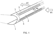
- Figure 1 shows one application for the inventions disclosed herein on the leading edge of an aircraft wing 1.
- the wing 1 comprises a leading edge 2 which is a curved profile forming the front or upstream part of the wing.
- the wing creates lift by separating airflow into two stream on the upper and lower surfaces of the wing.
- leading edge 1 Extending from the top and bottom surface of the leading edge 1 are the trailing regions 3 or areas which extend from the leading edge away from the front of the wing towards the trailing edge (not shown at the rear of the wing). Only a section of the wing is shown in figure 1 but it will be recognised that the wing extends from the fuselage of the aircraft to the wing tip.
- the arrows 4A, 4B and 4C show the airflow over the surfaces. As the aircraft is pushed through the air the air 4A approaches the wing leading edge 2 and impinges or collides with the surface. Air is directed as shown by arrow 4B around the curved surface towards the flow 4C on the upper surface of the wing. The same occurs on the lower surface of the wing.
- Air impinging on the leading edge may contain water vapour and owing to the altitude of aircraft the airframes can become extremely cold causing ice to form on the wing surfaces.
- the disclosures herein provide a variety of novel ways to de-ice or release ice from these wing surfaces (as well as other aerodynamic surfaces) using a particular laminate structure which provides an electrically operable actuator surface optionally in combination with an electrical heater.
- actuator is intended to refer to something that causes movement i.e. displacement. By causing displacement of a surface at the wing surfaces ice can be caused to crack and/or break away from the wing surface.
- de-icing apparatus 5 and 6 are located not along the front of the leading edge but on a trailing portion of the wing relative to the leading edge i.e. adjacent to the leading edge but down-stream from it in an airflow direction.
- the laminate structure of the de-icing apparatus described herein will have a shape corresponding to the particular profile of the aerodynamic component to which it is applied.
- a leading edge of a wing is shown and thus the de-icing apparatus would have a curved, somewhat semi-circular profile as illustrated in figure 1 .
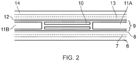
- Figure 2 shows such a cross-section through the laminate structure forming part of the deicing apparatuses described herein.
- the laminate is arranged for connection to the aircraft outer surface and comprises (working from the bottom layer shown in figure 2 ) a thermoplastic backing layer 6.
- An electrical circuit 7 is formed on the layer 6 by etching copper tracks which can receive electrical power. This circuit or track provides the electrical heated circuit described below.
- the copper tracks 7 are sandwiched between layer 6 and another thermoplastic layer 8.
- the central portion 9 of the laminate comprises an electrically operable actuator 10 which will be described with reference to figure 3 below.
- Figure 2 illustrates the optional filler portions 11A and 11B which are located on either side of the actuator 10 and which fill in the spaces between layer 8 and the next thermoplastic layer 12 located above the actuator 10. These filler fill the gaps created in the laminate by the thickness of the actuator 10 and provide a uniform thickness and outer surface to the overall laminate.
- thermoplastic layer 12 is applied to the top of the thermoplastic layer 12 in a profile (layout) that corresponds to the desired heat output profile that is desired for the heated region.
- a further upper thermoplastic layer 14 formed the upper surface of the di-icing apparatus.
- a further erosion shield may be applied to the upper surface 14 and a corresponding composite or metallic backing layer to the lower surface of layer 6. Both not shown.
- thermoplastic material Any suitable thermoplastic material may be used for the laminate layers.
- PEEK polyetheretherketone
- EAK is particularly suitable owing to its electrical insulation properties and thermal conductivity.
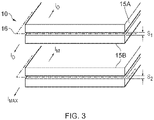
- the centrally located actuator 10 will now be described with reference to figure 3 .
- the actuator's function is to cause relative movement of one portion 15A with respect to the other half of the actuator 15B.
- The may be achieved according to Ampere's force law i.e. that attractive or repulsive forces can be generated between electrical conductors that are adjacent to each other by supplying opposing current directions.
- the embedded actuator according to the arrangement shown in figure 3 is provided with a current in a first direction in actuator half 15A and an opposing current direction in the other half of the actuator 15B.as illustrated by I 0 and I Max and the associated arrows in figure 3 .
- the two actuator halves 15A and 15B are electrically separated and isolated by an insulator 16 located between the two.
- This may for example be an additional layer of PEEK or a release layer of a suitable dielectric material such as, for example, Polyimide.
- the upper image in figure 3 shows a situation when the actuators 15A and 15B are not electrically excited i.e. there is no electrical current passing through the two halves. No forces are generated and the separation of the two halves is S 1
- the lower image in figure 3 shows a situation when the actuators 15A and 15B are provided with an electrical current I Max .
- Ampere's force law means that as a result of the opposing current directions and the associated generation of magnetic fields the two halves are pushed apart creating a separation S 2 where S 2 > S 1 .
- This functionality of the actuator 10 is embedded into the middle of the de-icing apparatus shown in figure 2 .
- the inventor have established that by pulsing a current through the actuator 10 extremely powerful impulses can be generated over very small distances. For example 10,000G over 1mm.
- This rapid impulse allows the surface of the de-icing apparatus immediately above the actuator to be rapidly displaced over this small distance meaning that the connection or adhesion between ice on the surface and the outer surface of the apparatus can be broken or disturbed.
- FIG. 4 illustrates schematically the electrical circuit forming each actuator portion. It will be recognised that each apparatus may comprise multiple such actuators extending along the length of the apparatus or arranged over discrete areas or zones.
- an electrical supply and controller 17 is provided which can provide the necessary current and switching capability.
- the two halves are electrically connected together such that current is returned in an opposing direction. It will be recognised that the opposing current flows may be achieved in other electrical ways.
- the controller may advantageously be configured to apply currents to multiple such actuators to cause ripples in the de-icing surface or even waves by applying currents are predetermined times or in particular sequences.
- One or more actuators may be used to create complex waves or forces.
- a single actuator could create a ripple in a defined locality on a surface, but a number of actuators would allow a stronger ripple (or complex wave) to be created and this could spread over a larger surface and depending on the positioning of the actuators, could allow for different degrees of force to be applied in selected localities.
- Some areas may collect more ice than others, for example because of profile and/or airflow, and these areas may have more actuators.
- a combination of single or multiple actuators may be used depending on the desired configuration in order to provide a targeted degree of ice removal depending on the location and extent of ice build-up.
- Figure 5 shows how the actuator extends in on example as a pair of parallel tracks 15A 15B in a z direction. As shown the two halves of the actuator are substantially overlapping. This, in combination with their close proximity to each other and then depth maximises the effectiveness in the de-icing application since it maximises the impulse that can be generated whilst minimising the thickness. This reduces weight and allows complex geometries to be followed.
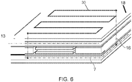
- Figure 6 illustrates the electrical path between the power supply layer 7 and the heater layer 13.
- a shown a series of electrical connections 16 are provided through the laminate allowing power to be communicated from a power supply to the de-icer (not shown but located on the inner surface of the apparatus) to the heater circuit proximate to the outer surface of the deicing apparatus.
- the layer 13 has an alternative path 30 which dissipates heat in the design profile on the upper surface 18.
- Figure 7 shows two alternative arrangements for the profile of the actuators.
- a uniform profile is shown. Such a profile will generate uniform impulses along the length of the actuator.
- Figure 7B shows an alternative arrangement in which the actuator is non-uniform and comprises regions with narrower width 19 and greater width 20. In regions of narrower width the will be greater current concentration and consequently (assuming the opposing actuator is the same) greater opposing forces.
- Such an arrangement allows for the optimisation of forces and thereby movement along the length of the apparatus.
- By adapting the two halves of the actuator the forces and displacements for a given current can be optimised and adapted to provide precisely the desired displacement of the de-icing apparatus over complex geometries.
- the heating element described above is optional and the de-icing apparatus may utilise the actuator concept at a separate location to the actuator.
- Figure 8A shows a situation where ice has built up on the leading edge of the wing.
- an electrical heater 21 is provided at the leading edge surface and may be activated once ice has built up.
- the heater can be activated in combination with the de-icing systems 22 located in the trailing regions of the wing.
- the de-icing apparatus 22 may optionally include and electrical heating layer and in combination with the leading edge heater 21 (formed using a conventional heater mat for example) may provide a hybrid anti-icing system using less electrical energy than heating the entire leading edge. Only a portion of the leading edge need require conventional heating mat technology.
- the de-icing apparatus is located immediately adjacent to the leading edge heater.
- Figure 8B shows how ice has been removed.
- Figure 9A and 9B show a further alternative approach, not falling within the scope of the claims, wherein a heater 21 is again provided at the leading edge.
- the de-icing apparatus 22 is located further towards the trailing edge of the wing.
- an alternative approach is applied to ice removal. Specifically, the ice is melted by the leading edge heater 21 and allowed to flow towards the trailing edge of the wing. Once the water leaves the heated areas at the leading edge it begins to freeze.
- the de-icing apparatus 22 is that optimally position at a position where the ice begins to freeze.
- Activation of the actuators allows the newly frozen ice to be periodically released from the surface by activating of firing the actuators within the laminate layer as described above.
- the ice is melted and allowed to reform at a region where the actuators can be positioned.
- ice can be removed from the wing surface using less electrical power.
- the electro-thermal sub-system has by far the greater power consumption, and therefore its physical extent, temperature and duration of operation should be minimised.
- the electro-mechanical sub-system has relatively low power consumption and therefore its effective operation should be maximised.
- a further potential development of this invention would be to include in the leading edge component an optical ice detection device which provides both detection of icing conditions and measurement of ice thickness. This could be used to automate IPS activation in the presence of icing conditions and/or once the required level of ice accretion has been reached for the system to be effective.
- This OID could be housed inside the surface to be protected, rather than relying on sensors from other parts of the aircraft which may not reflect the local conditions or ice accretion.
- Such a development would result in a "smart" IPS able to operate automatically and with optimal efficiency.
- the technology used could be the GKN OID sensor currently in development in other projects.
- Figures 10 and 11 show a still further arrangement for de-icing not falling within the scope of the claims.
- leading edge heater is replaced with a fluid based system in which an ice dissolving fluid is secreted through a conduit 23 and optional permeable leading edge surface 24.
- hybrid low-power IPS configuration
- the system is composed of both electro-thermal and FPD fluid sub-systems, which work together to prevent, manage and remove ice formation on aircraft surfaces so that it remains within allowable limits for aircraft handling and performance.
- This solution is the arrangement, integration and method of operation as a single hybrid solution.
- the hybrid solution reduces the operational restrictions associated with existing FPD fluid ice protection systems, whilst using less power than electro-thermal ice protection systems.
- the electro-thermal sub-system has by far the greater power consumption, and therefore its physical extent, temperature and duration of operation should be minimised.
- the FPD fluid sub-system has relatively low power consumption (only a fluid pump is required) and therefore its effective operation should be maximised. However it also requires a continuous supply of FPD fluid during its activation, which has to be stored on the aircraft and transported to the required areas.
- the hybrid system overall has:
- the heaters are downstream of the FPD fluid panel and physically separated from it.
- the general principle of operation is as follows:
- the heaters are configured to also cover the FPD fluid panel area, thus further reducing the amount of FPD fluid needed.
- the heater used in this area would need to be compatible with the perforations required for secretion of the FPD fluid.
- the FPD-fluid panel and runback heater areas should be optimised in order to achieve the desired balance of fluid delivery/storage requirements (i.e. fluid flow rate) and power consumption (impacted most greatly by heater size and temperature).
- fluid delivery/storage requirements i.e. fluid flow rate
- power consumption impacted most greatly by heater size and temperature.
- the exact trade-off for any given application will be determine by a large number of factors including required endurance, allowable ice shapes, weight, space and available power.
- the technology used for the electro-thermal heating could employ the thin film, thermoplastic heater mat technology. If the configuration described in figure 11 is adopted, a different heater technology may be required in order to make the heater compatible with the perforated skin surface and the passage of FPD fluid through it.
- a further potential development of this invention would be to include in the leading edge component an optical ice detection device which provides both detection of icing conditions and measurement of ice thickness. This could be used to automate IPS activation in the presence of icing conditions and/or once the required level of ice accretion has been reached for the system to be effective.
- This OID could be housed inside the surface to be protected, rather than relying on sensors from other parts of the aircraft which may not reflect the local conditions or ice accretion.
- Such a development would result in a "smart" IPS able to operate automatically and with optimal efficiency.
- the technology used could be the GKN OID sensor currently in development in other projects.
Landscapes
- Engineering & Computer Science (AREA)
- Aviation & Aerospace Engineering (AREA)
- Mechanical Engineering (AREA)
- Control Of Resistance Heating (AREA)
- Surface Heating Bodies (AREA)
Description
- The present invention is concerned with aerospace ice-protection systems and specifically, but not exclusively, to an ice-protection system that is capable of being used with small to medium sized aircraft as well as larger commercial aircraft.
- Aerospace surfaces such as wing leading edges or engine nacelles (or the like) are prone to ice accretion during flight as the cold outer surfaces of the component come into contact with water during flight, landing, taxi or take-off.
- Ice build-up can change the aerodynamic profile or shape of the component thus changing the functionality of the component. This can have disastrous consequences. In an engine nacelle ice may be ingested into the engine again potentially have very serious and dangerous results.
- To solve these issues a number of heating systems have been employed in different aircraft. One system involves using hot exhaust gas from the engines which can be directed to the desired surface (for example along the leading edge of a wing). This has the advantage of using the unwanted heat from the exhaust gas. In an alternative arrangement electrical heaters are applied to the aircraft surfaces prone to icing and an electrical current passed through the heaters. The advantage of this system is that it allows complex and distributed heating systems to be deployed around the aircraft. In fact this system has become the industry's preferred solution to ice accretion.
- However, a drawback of electrical heating systems is their complexity and power consumption which must be fed from the electrical generators in the engines. In larger aircraft, for example with multiple engines, the electrical generators have the capacity to power the electrical heaters. This is not the case for smaller aircraft.
- The inventors of an invention described herein have however created an alternative de-icing system which minimised electrical consumption whilst maintaining de-icing capability.
-
US 6,283,411 B1 discusses a de-icer comprising a skin heating means immediately subjacent an outer skin overlying an apex of a leading edge, and a skin deflection means immediately subjacent the outer skin chordwise aft of the apex. The skin heating means prevents the formation of ice over the apex and the skin deflection means deflects the outer skin to expulse ice formed chordwise aft of the apex. A controller controls the heating and deflection cycles to minimize power consumption of the de-icer. -
US 5,553,814 A discusses an aircraft de-icing assembly for attachment to an airfoil including a deflection shell disposed over a deflection means. The deflection shell is comprised of a primary layer comprised of a high strength fabric reinforced with a phenolic resin and a backing layer comprised of a high strength fabric reinforced with an epoxy resin. The thickness of the backing layer is varied as a function of curvature of the airfoil and spanwise length of the airfoil. -
US 4,875,644 A discusses an electroexpulsive separation apparatus suitable for deicing leading edges of aircraft which includes a pair of sheet-like arrays each containing in spaced-apart relationship a plurality of parallel ribbon-shaped electrically conductive members. The electrically conductive members are electrically interconnected such that any electrical current flowing in the conductive members flows in the same direction in adjacent electrically conductive members in the first sheet like member and also flows in adjacent electrically conductive members of the second sheet-like array in a direction opposite. The first and second sheet-like arrays are coextensive and superposed proximate to each other such that the electrically conductive members of the first and second sheet-like members are substantially parallel. The electrically conductive members are electrically insulated from one another. Large current pulses of predetermined magnitude, shape and duration are fed to the conductors from a power storage unit resulting in rapid and forceful separation of the first and second sheet-like arrays and other members associated therewith. - However, none of these documents disclose at least the following features of appended claim 1: wherein the laminate is in the form of: a first thermoplastic heat dissipation layer; a second electrically operable heating element layer; a third electrically insulating thermoplastic layer; a fourth electrically insulating thermoplastic layer; a fifth electrical power supply layer; and a sixth thermoplastic backing layer wherein an electrical actuator is located between the third and fourth thermoplastic layers, and wherein the second electrically operable heating element layer overlaps the electrical actuator.
- Aspects of the invention are set out in the accompanying claims.
- Viewed from a first aspect of an invention disclosed herein there is provided a de-icing apparatus according to
claim 1. - Thus, an apparatus is provided which combines a conventional electrical heater with an expandable or movable structure. Specifically, the expansion is in a direction perpendicular to the surface of the conventional heater surface such that the surface displaces outwards from the surface onto which it is formed or connected. Parts of the surface can thereby be configured to move away or out of the conventional surface to disturb the shape or contours of the conventional surface.
- The invention described herein thereby provides a combination or hybrid ice removal system that can simultaneously heat a surface and displace a surface and this advantageously allows ice can be both melted and mechanically or physically cracked or pushed away from the surface.
- Aircraft regulations require aircraft which encounter icing conditions to be equipped with a mechanism to prevent or remove the formation of ice on wings and control systems. As discussed above aircraft typically achieve this by bleeding hot gases from the engine or using electrical heating elements on the leading-edge structures.
- Examples of this technology include the Boeing 787, which incorporates a heater mat technology. As also described above, the application of this technology to smaller aircraft is however limited by the ability of the aircraft to generate sufficient electrical power.
- The inventors have created a thin, flexible, single-layer integrated heater and actuator manufactured from a combination of etched and/or deposited metallic tracks encapsulated within a thermoplastic/glass fibre composite laminate. This is in contrast to existing examples of ice removal systems which use discrete, separate components for actuation and heating which then have to be assembled.
- The system described herein is applicable to any surface on which ice may build up. In an aircraft skin application, for example, the integrated functional layer may be bonded between a thin metallic erosion shield skin and a structural composite or metallic skin. Such an arrangement
- The system described herein provides a number of technical advantages including:
- The actuators inside the functional layer are close to the surface, meaning that the efficient deflection of the surface can be achieved without compromising structural stiffness, and whilst still being protected from damage and environmental conditions, and whilst avoiding surface deformation/waviness.
- The actuators in the functional layer are supported by the structural skin (no additional backing structure needed - saves weight and space) .
- Frees up space inside the structure (only wire routing required) .
- Actuator performance is immune to the proximity of structural nodes (e.g. ribs) and can be located at any point along the structure.
- In this configuration there will be no access to actuators for repair or maintenance. An actuator (or heater) failure would require replacement of the functional layer, if it is designed to be de-mountable, or replacement of the leading edge skin.
- In this configuration there is potentially a failure mode through wet arc tracking at any locations where the thermoplastic functional layer is exposed to the internal environment inside the structure (e.g. near the cut-out in the structural skin for wiring access) .
- There is no "dead zone" between the heater and the actuator, improving performance as a de-icer .
- The hybrid functional layer incorporates the actuator by extending the use of manufacturing processes and materials already being developed by GKN for thermoplastic thin film heater mats (etched copper foils) .
- The functional layer (with the exception of the wiring terminations) is entirely conformal and minimises the impact of the system from a integration perspective.
- The functional layer can be supplied for assembly as a single, flexible layer in the manufacturing process for the aircraft structure in question, reducing manufacturing costs.
- There may be new failures modes introduced which are associated with the internal release layer and the cavity that is formed each time the actuator is fired. These would be mainly defined in terms of degradation of the laminate integrity through fatigue loading.
- The thermoplastic/glass functional layer laminate incorporates the following:
- Etched copper actuator conductors, arranged as a pair of parallel conductors one on top of the other with a controlled gap. When a high-current pulse is supplied in opposite directions in each conductor, the electro-magnetic forces cause them to repel and move apart with considerable force. The magnitude of deflection achieved is of the order 0.5-1.0mm.
- A release layer between the actuator conductor which maintains a minimum gap and allows the conductors to move apart without damaging the surrounding laminate. After the actuator has fired, the conductors should return to their original position under the influence of vacuum forces.
- Etched copper heating element terminations and bus bars
- Deposited metallic heating elements, close to the OML (outer mould line) of the laminate and electrically insulated from the actuator conductors.
- Advantageously a configuration described herein means that (amongst other things):
- There is no "dead zone" between the heater and the actuator, improving performance as a de-icer
- The hybrid functional layer incorporates the actuator by extending the use of manufacturing processes and materials already being developed by GKN for thermoplastic thin film heater mats (etched copper foils)
- The functional layer (with the exception of the wiring terminations) is entirely conformal and minimises the impact of the system from a integration perspective
- The functional layer can be supplied for assembly as a single, flexible layer in the manufacturing process for the aircraft structure in question, reducing manufacturing costs.
- There may be new failures modes introduced which are associated with the internal release layer and the cavity that is formed each time the actuator is fired.
- These would be mainly defined in terms of degradation of the laminate integrity through fatigue loading.
- The laminate structure is in the form of:
- a first thermoplastic heat dissipation layer;
- a second electrically operable heating element layer;
- a third electrically insulating thermoplastic layer;
- a fourth electrically insulating thermoplastic layer;
- a fifth electrical power supply layer; and
- a sixth thermoplastic backing layer
- wherein an electrical actuator is located between the third and fourth thermoplastic layers.
- Thus, a multi-layer laminate is defined including an actuator within i.e. embedded or encapsulated within the laminate.
- The actuator must be thin to minimise the weight of the system and thus, advantageously the electrical actuator may be in the form of a pair of opposing electrical conductors separated by an electrical insulator.
- Ampere's force law means that a repulsive force can be generated between two conductors by virtue of the magnetic field each conductor generates and the interaction of those fields. Thus, a very small movement can be generated in the laminate structure using this principle. Pulsing an electrical current can cause pulses in movement of the actuator and thus pulses in movement of the surface of the laminate which is caused to rise and fall as the pulse current is applied.
- The conductors may be any suitable shape depending on the application and shape of the surface to be de-iced.
- Advantageously the opposing electrical conductors may be in the form of parallel and overlapping electrically conductive tracks. By overlapping the tracks the maximum force effect can be realised.
- To allow for the movement and for the generation of the force the tracks must be electrically insulated from one another. For example, the opposing electrical conductors may be separated by an elastomeric layer, with suitable mechanical dielectric strength for the voltages in use.
- One or both of the conductors may be free to move to maximise the movement created by the Ampere law i.e. one or both of the electrical conductors may be free to move relative to the electrical insulator. Thus, the movement can be translated to the outer surface of the deicing structure since the conductor movement is not inhibited by being bonded or connected to the insulator.
- To electrically excite or energise the apparatus the electrical conductors are arranged in use to be electrically coupled to an electrical supply.
- Also, in order to achieve the Ampere law effect the electrical conductors are electrically connected together at one end and arranged to be electrically coupled to an electrical supply at the other end.
- In order to make the laminate structure continuous, the structure may be provided with thermoplastic fillers located adjacent to each of the electrical conductors between the third and fourth thermoplastic layers. These fillers 'fill' the gap in the laminate created by the thickness of the two conductors and the insulating layer between them.
- In order to provide power to the heating layer an electrical path may be provided between the second electrically operable heating element layer and the fifth electrical power supply layer.
- The heating element itself may be a serpentine track for example of conducting copper for example. Passing a current through the track create heat.
- The heating element may be applied in a variety of conventional ways or using more advanced techniques such as flame sprayed copper. The electrical conductors and the electrical power supply layer may similarly be applied in a variety of ways including, for example, copper etched layers.
- The choice of layers will be dependent on whether it is arranged to carry current to create heat, or to supply the current (without creating heat) to a location where it will be used to create heat.
- To form a solid state apparatus or de-icing layer or mat the laminate may be cured together, for example in an autoclave where a thermoplastic material softens and adheres to an adjacent layer. Thus, adjacent layers which are immediately adjacent are connected to each other - with the exception of course of the two opposing electrical conductors.
- Thus, in effect, a laminate structure is formed comprising a plurality of thermoplastic layers encapsulating a plurality of electrical conducting layers.
- As discussed above the insulator between the two conductors must be configured to allow the one or both conductors to move apart relative to one another. To achieve this the electrical insulator located between the electrical conductors may be in the form of a thermoplastic material comprising a discontinuity allowing the insulator outer surfaces to move apart relative to each other.
- For example, the discontinuity may be in the form of a slit extending in a plane within the layer and parallel with the outermost surfaces of the layer. This slit or discontinuity allows the insulator to expand such that if it is coupled to the conductors they may still move. In an alternative arrangement one or both of the conductors may be un-bonded to the outer surfaces of the insulator thereby achieving the same effect.
- It will be recognised that there are many ways the layers can be configured to allow for relative movement of the two conductors whilst maintaining their electrical isolation. For example in another arrangement the electrical insulator could be in the form of two independent sub-layers immediately adjacent to each other.
- A variety of material may be used for the layers within the laminate. For example, a polyetheretherketone (PEEK) material may be used for one or each of the thermoplastic and insulating layers.
- The conductors forming the actuator may be any suitable shape. Advantageously the conductors may be overlapping elongate tracks having a constant width and cross-section. Thus a uniform force and movement may be created.
- The tracks may be configures to follow the contour of the aerodynamic shape which is to be de-iced and may be continuous or curved, zig-zag or any desired shape.
- By changing the surface area and or cross-sectional thickness of the conductors different current densities can be created thereby allowing different displacements or movement to be achieved along the conductor and de-icing apparatus. For example, the electrical conductors may be overlapping elongate tracks with varying widths defining regions of greater and less surface areas. Non-uniform displacements can then be created.
- Additionally, areas of greater displacement i.e. greater force may advantageously be aligned with structural components of the aerospace component thus ensuring the forces do not damage any delicate or fragile parts of the structure. In a wing, the regions of greater force could for example be arranged to align with the ribs of a wing for example.
- The outer surface of the apparatus may also be provided with a metallic erosion shield skin. A structural composite or metallic skin may also be applied on a second opposing side of the apparatus. Thus, a premade de-icing system can be manufactured and delivered for installation.
- It will be recognised that the de-icing apparatus is particularly applicable to leading edges or nacelles of aerodynamic components which will be curved or have rounded contours. The layers can thus be formed in a shape corresponding to the desired application profile.
- Viewed from another aspect of an invention described herein there is provided a de-icing system for an aircraft comprising the de-icing apparatus of the first aspect and one or more electrical control and supply devices arranged to electrically excite the electrical heating element and the electrical actuator. A complete system may thereby be provided.
- The conductors may be excited in a variety of different manners to achieve different displacements, different displacement profiles and/or different resonances or waves along the apparatus. Also, depending on the application a component such as a wing may comprise more than one de-icing apparatus which may advantageously be simultaneously or independently controlled. Independent control allows the electrical power requirements of the de-icing system to be managed; a particularly important aspect for smaller aircraft.
- Viewed from a still further aspect, there is provided a method of manufacturing the de-icing apparatus for an aircraft of the first aspect comprising the steps of:
- (A) forming a laminate structure comprising at least:
- a first thermoplastic heat dissipation layer;
- a second electrically operable heating element layer;
- a third electrically insulating thermoplastic layer;
- a fourth electrically insulating thermoplastic layer;
- a fifth electrical power supply layer; and
- a sixth thermoplastic backing layer
- wherein an electrical actuator is located between the third and fourth thermoplastic layers; and
- (B) curing the structure to bond one or more of the layers together to form a continuous structure.
- Thus, a method of manufacturing a de-icing apparatus and system is thereby provided in which a laminate structure is laid-up and then cured to create a continuous structure. Another arrangement of de-icing an aerospace component such as a wing involves secreting a de-icing fluid onto the surface which has frozen. In effect a liquid is released onto the surface which causes the ice to break down and can then flow away from the critical zones or areas of the aerospace component. Such liquids are known as freezing point depression liquids or FPDs. One such example is an ethylene glycol-based fluid.
- Advantageously, in a further aspect, the de-icing apparatus of the first aspect may be used in combination with such a fluid ice protection system. In the same way that the conventional heating mat described above may be used in combination with the actuator and heater described herein it may be used in precisely the same way with a fluid system i.e. located down-stream of the leading edge area where the fluid is deployed.
- Using the de-icing apparatus described herein presents a number of advantages for fluid systems (which are often used for emergencies since large volumes of liquid cannot be carried on board the aircraft).
- For example, locating a de-icing apparatus described herein down-stream but adjacent to a leading edge using a fluid secretion systems allows the fluid to flow for a longer period along the wing without re-freezing, it also allows for smaller quantities of fluid to be carried and/or lower concentrations of fluid to be used having environment benefits.
- The fluid itself may be secreted for example from a conduit at or near to the leading edge.
- For example, a region of the apparatus aligning with the leading edge may comprise a perforated surface for communication of fluid from the conduit through the leading edge.
- To further enhance the arrangement the perforated surface may additionally include an electrical heater arranged in use to heat the leading edge surface.
- It will be recognised that the present disclosures may be applied to a variety of aerospace surfaces including, but not limited to aircraft wings, tail, stabilisers, engine nacelles, helicopter rotor blades and so forth.
- One or more embodiments of the invention will now be described, by way of example only, and with reference to the following figures in which:
-
Figure 1 shows a schematic of leading edge of an aircraft wing; -
Figure 2 shows cross-section through a actuator/heating apparatus as described herein; -
Figure 3 illustrates the separation and operation of the actuator; -
Figure 4 illustrates an electrical circuit for the actuator; -
Figure 5 shows a configuration of the actuator within the apparatus laminate structure; -
Figure 6 shows the electrical connections from the power delivery layer to the heating circuit and an example of the heating circuit path; -
Figure 7 shows two alternative profiles of actuator tracks; -
Figures 8 and 9 show a further hybrid de-icing system , not falling within the scope of the claims, optionally incorporating an actuator; and -
Figure 10 and 11 show a still further fluid de-icing system, not falling within the scope of the claims, again optionally incorporating an actuator. - Any reference to prior art documents in this specification is not to be considered an admission that such prior art is widely known or forms part of the common general knowledge in the field. As used in this specification, the words "comprises", "comprising", and similar words, are not to be interpreted in an exclusive or exhaustive sense. In other words, they are intended to mean "including, but not limited to". The invention is further described with reference to the following examples. It will be appreciated that the invention as claimed is not intended to be limited in any way by these examples. It will also be recognised that the invention covers not only individual embodiments but also combination of the embodiments described herein.
- The various embodiments described herein are presented only to assist in understanding and teaching the claimed features. These embodiments are provided as a representative sample of embodiments only, and are not exhaustive and/or exclusive. It is to be understood that advantages, embodiments, examples, functions, features, structures, and/or other aspects described herein are not to be considered limitations on the scope of the invention as defined by the claims, and that other embodiments may be utilised and modifications may be made without departing from the scope of the claimed invention.
-
Figure 1 shows one application for the inventions disclosed herein on the leading edge of anaircraft wing 1. - The
wing 1 comprises aleading edge 2 which is a curved profile forming the front or upstream part of the wing. The wing creates lift by separating airflow into two stream on the upper and lower surfaces of the wing. - Extending from the top and bottom surface of the
leading edge 1 are the trailingregions 3 or areas which extend from the leading edge away from the front of the wing towards the trailing edge (not shown at the rear of the wing). Only a section of the wing is shown infigure 1 but it will be recognised that the wing extends from the fuselage of the aircraft to the wing tip. - The
arrows air 4A approaches thewing leading edge 2 and impinges or collides with the surface. Air is directed as shown by arrow 4B around the curved surface towards theflow 4C on the upper surface of the wing. The same occurs on the lower surface of the wing. - Air impinging on the leading edge may contain water vapour and owing to the altitude of aircraft the airframes can become extremely cold causing ice to form on the wing surfaces.
- The disclosures herein provide a variety of novel ways to de-ice or release ice from these wing surfaces (as well as other aerodynamic surfaces) using a particular laminate structure which provides an electrically operable actuator surface optionally in combination with an electrical heater.
- The term actuator is intended to refer to something that causes movement i.e. displacement. By causing displacement of a surface at the wing surfaces ice can be caused to crack and/or break away from the wing surface.
- Only small movements are required for this to be achieved as will be described. What is required is sufficient movement of the surface to break the adhesion between the ice and the outer surface of the wing (or aerodynamic component). The high velocity airflow then carries the ice away from the surface.
- Returning to
figure 1 the possible position of the de-icing system is shown by de-icing apparatus 5 and 6. As shown they are located not along the front of the leading edge but on a trailing portion of the wing relative to the leading edge i.e. adjacent to the leading edge but down-stream from it in an airflow direction. - It will be recognised that the laminate structure of the de-icing apparatus described herein will have a shape corresponding to the particular profile of the aerodynamic component to which it is applied. In
figure 1 a leading edge of a wing is shown and thus the de-icing apparatus would have a curved, somewhat semi-circular profile as illustrated infigure 1 . - The structure of a laminate forming a de-icing apparatus described herein will now be described in which a slice through the cross-section of the laminate is illustrated.
-
Figure 2 shows such a cross-section through the laminate structure forming part of the deicing apparatuses described herein. - The laminate is arranged for connection to the aircraft outer surface and comprises (working from the bottom layer shown in
figure 2 ) a thermoplastic backing layer 6. Anelectrical circuit 7 is formed on the layer 6 by etching copper tracks which can receive electrical power. This circuit or track provides the electrical heated circuit described below. - The copper tracks 7 are sandwiched between layer 6 and another
thermoplastic layer 8. - The
central portion 9 of the laminate comprises an electricallyoperable actuator 10 which will be described with reference tofigure 3 below.Figure 2 illustrates theoptional filler portions actuator 10 and which fill in the spaces betweenlayer 8 and thenext thermoplastic layer 12 located above theactuator 10. These filler fill the gaps created in the laminate by the thickness of theactuator 10 and provide a uniform thickness and outer surface to the overall laminate. - Next a flame sprayed or otherwise
copper heating circuit 13 is applied to the top of thethermoplastic layer 12 in a profile (layout) that corresponds to the desired heat output profile that is desired for the heated region. Finally a furtherupper thermoplastic layer 14 formed the upper surface of the di-icing apparatus. - Optionally a further erosion shield may be applied to the
upper surface 14 and a corresponding composite or metallic backing layer to the lower surface of layer 6. Both not shown. - Any suitable thermoplastic material may be used for the laminate layers. However, polyetheretherketone (PEEK) is particularly suitable owing to its electrical insulation properties and thermal conductivity.
- The centrally located
actuator 10 will now be described with reference tofigure 3 . The actuator's function is to cause relative movement of oneportion 15A with respect to the other half of theactuator 15B. The may be achieved according to Ampere's force law i.e. that attractive or repulsive forces can be generated between electrical conductors that are adjacent to each other by supplying opposing current directions. - The embedded actuator according to the arrangement shown in
figure 3 is provided with a current in a first direction inactuator half 15A and an opposing current direction in the other half of the actuator 15B.as illustrated by I0 and IMax and the associated arrows infigure 3 . - Importantly the two
actuator halves insulator 16 located between the two. This may for example be an additional layer of PEEK or a release layer of a suitable dielectric material such as, for example, Polyimide. - The upper image in
figure 3 shows a situation when theactuators - The lower image in
figure 3 shows a situation when theactuators - This functionality of the
actuator 10 is embedded into the middle of the de-icing apparatus shown infigure 2 . - The inventor have established that by pulsing a current through the
actuator 10 extremely powerful impulses can be generated over very small distances. For example 10,000G over 1mm. - This rapid impulse allows the surface of the de-icing apparatus immediately above the actuator to be rapidly displaced over this small distance meaning that the connection or adhesion between ice on the surface and the outer surface of the apparatus can be broken or disturbed.
-
Figure 4 illustrates schematically the electrical circuit forming each actuator portion. It will be recognised that each apparatus may comprise multiple such actuators extending along the length of the apparatus or arranged over discrete areas or zones. - As shown in
figure 4 at a first end an electrical supply andcontroller 17 is provided which can provide the necessary current and switching capability. At the opposing end the two halves are electrically connected together such that current is returned in an opposing direction. It will be recognised that the opposing current flows may be achieved in other electrical ways. - The controller may advantageously be configured to apply currents to multiple such actuators to cause ripples in the de-icing surface or even waves by applying currents are predetermined times or in particular sequences.
- One or more actuators may be used to create complex waves or forces. For example, a single actuator could create a ripple in a defined locality on a surface, but a number of actuators would allow a stronger ripple (or complex wave) to be created and this could spread over a larger surface and depending on the positioning of the actuators, could allow for different degrees of force to be applied in selected localities. Some areas may collect more ice than others, for example because of profile and/or airflow, and these areas may have more actuators. A combination of single or multiple actuators may be used depending on the desired configuration in order to provide a targeted degree of ice removal depending on the location and extent of ice build-up.
-
Figure 5 shows how the actuator extends in on example as a pair ofparallel tracks 15A -
Figure 6 illustrates the electrical path between thepower supply layer 7 and theheater layer 13. A shown a series ofelectrical connections 16 are provided through the laminate allowing power to be communicated from a power supply to the de-icer (not shown but located on the inner surface of the apparatus) to the heater circuit proximate to the outer surface of the deicing apparatus. As illustrated thelayer 13 has analternative path 30 which dissipates heat in the design profile on theupper surface 18. -
Figure 7 shows two alternative arrangements for the profile of the actuators. In figure 7A a uniform profile is shown. Such a profile will generate uniform impulses along the length of the actuator. - Figure 7B shows an alternative arrangement in which the actuator is non-uniform and comprises regions with
narrower width 19 andgreater width 20. In regions of narrower width the will be greater current concentration and consequently (assuming the opposing actuator is the same) greater opposing forces. Such an arrangement allows for the optimisation of forces and thereby movement along the length of the apparatus. By adapting the two halves of the actuator the forces and displacements for a given current can be optimised and adapted to provide precisely the desired displacement of the de-icing apparatus over complex geometries. - The heating element described above is optional and the de-icing apparatus may utilise the actuator concept at a separate location to the actuator.
- Referring to
figures 8A and 8B an alternative de-icing apparatus, not falling within the scope of the claims, is shown in which the -
Figure 8A shows a situation where ice has built up on the leading edge of the wing. Here anelectrical heater 21 is provided at the leading edge surface and may be activated once ice has built up. The heater can be activated in combination with thede-icing systems 22 located in the trailing regions of the wing. Thede-icing apparatus 22 may optionally include and electrical heating layer and in combination with the leading edge heater 21 (formed using a conventional heater mat for example) may provide a hybrid anti-icing system using less electrical energy than heating the entire leading edge. Only a portion of the leading edge need require conventional heating mat technology. Here the de-icing apparatus is located immediately adjacent to the leading edge heater.Figure 8B shows how ice has been removed. -
Figure 9A and 9B show a further alternative approach, not falling within the scope of the claims, wherein aheater 21 is again provided at the leading edge. However, in this arrangement thede-icing apparatus 22 is located further towards the trailing edge of the wing. Here, an alternative approach is applied to ice removal. Specifically, the ice is melted by the leadingedge heater 21 and allowed to flow towards the trailing edge of the wing. Once the water leaves the heated areas at the leading edge it begins to freeze. Thede-icing apparatus 22 is that optimally position at a position where the ice begins to freeze. Activation of the actuators (and optional heating layer) allows the newly frozen ice to be periodically released from the surface by activating of firing the actuators within the laminate layer as described above. In this hybrid arrangement the ice is melted and allowed to reform at a region where the actuators can be positioned. - Again, ice can be removed from the wing surface using less electrical power.
- The two arrangements shown in
figures 9A and 9B allow a larger range of the wing to be de-iced for the same electrical consumption. The leading edge itself is de-iced using pure electrical heating power and the trailing regions are then de-iced using an actuator technique optionally in combination with an integrated electrical heating layer. - In this IDF, a "hybrid" low-power IPS configuration is proposed whereby the system is composed of both electro-thermal and electro-mechanical sub-systems, which work together to prevent, manage and remove ice formation on aircraft surfaces so that it remains within allowable limits for aircraft handling and performance. This solution is a combination of existing technologies, with the new idea being the arrangement, integration and method of operation as a single hybrid solution.
- Of these two sub-systems, the electro-thermal sub-system has by far the greater power consumption, and therefore its physical extent, temperature and duration of operation should be minimised.
- The electro-mechanical sub-system has relatively low power consumption and therefore its effective operation should be maximised.
- The hybrid system shown in
figures 8 and 9 exhibits a number of technical advantages including but not limited to: - Improved performance and reduced weight compared to IPS based solely on electro-mechanical IPS
- Unlimited endurance in icing conditions
- Reduced maintenance requirements/costs compared to existing FPD systems
- Significantly lower power requirement compared to fully electro-thermal solutions.
- These factors are particularly advantageous for smaller airframes whilst widening their ability to operate efficiently in icing conditions, as well as removing existing limitations on operation and endurance in those conditions.
- Operation of the two arrangements shown in
figures 8 and 9 can be summarised as follows: - 1) Hybrid De-Ice System
Figure 8 - a. The hybrid de-ice system is applicable where the airframe application can tolerate a certain amount of inter-cycle ice accretion during exposure to icing conditions.
- b. A certain amount of ice accretion is allowed to build up over the whole protected surface (see drawing i). This amount of ice has a certain minimum thickness for the system to be effective, and a maximum thickness defined by airframe allowable ice limits. Ice thickness may be known using a direct means of ice detection, or based upon knowledge of the environmental conditions.
- c. The heater is then activated for a duration which is just enough to either melt, or weaken the interface layer of ice immediately attached to the surface (i.e. to weaken the ice adhesion to the surface, but not to shed the ice)
- d. Electro-mechanical actuators are then fired to shed the ice from the surface (see drawing ii). This may result in a completely clean surface, or there may be some residual ice remaining, depending on the precise design parameters and ambient conditions.
- e. This process (b-d) is repeated cyclically while the IPS remains activated.
- 2) Hybrid Running-Wet De-Ice System
Figure 9 - a. The hybrid running-wet system is applicable where a portion of the surface is required to be maintained free of ice ("clean") during system activation, while a downstream portion of the surface can tolerate a certain amount of inter-cycle ice accretion.
- b. The area to be maintained free of ice is heated using an electro-thermal heater sufficiently so that its surface temperature is above 0°C, thus preventing impinging water droplets from freezing on the surface. This heating is maintained throughout the de-ice cycle.
- c. The liquid water which runs back beyond the rearward extent of the heated area then freezes as the surface temperature drops below 0°C. This is known as "runback ice". This ice accretion occurs over the area affected by the electro-mechanical actuator.
- d. The runback ice is allowed to build up to a thickness which is greater than a minimum value (defined by the thickness required for the expulsive action to be effective) and below a maximum value (defined by tolerances for aircraft handling). Ice thickness may be known using a direct means of ice detection, or based upon knowledge of environmental conditions.
- e. The electro-mechanical actuators are then fired to shed the runback ice from the surface. There may be residual ice remaining on this part of the surface after the actuation event.
- f. Steps d-e are repeated cyclically while the IPS is activated. The heater remains active throughout.
- As discussed above this method and arrangement may be conveniently used in combination with the electro-magnetic force actuators described herein.
- A further potential development of this invention would be to include in the leading edge component an optical ice detection device which provides both detection of icing conditions and measurement of ice thickness. This could be used to automate IPS activation in the presence of icing conditions and/or once the required level of ice accretion has been reached for the system to be effective. This OID could be housed inside the surface to be protected, rather than relying on sensors from other parts of the aircraft which may not reflect the local conditions or ice accretion. Such a development would result in a "smart" IPS able to operate automatically and with optimal efficiency. The technology used could be the GKN OID sensor currently in development in other projects.
-
Figures 10 and 11 show a still further arrangement for de-icing not falling within the scope of the claims. - In these arrangements the leading edge heater is replaced with a fluid based system in which an ice dissolving fluid is secreted through a
conduit 23 and optional permeableleading edge surface 24. - Here, a "hybrid" low-power IPS configuration is proposed whereby the system is composed of both electro-thermal and FPD fluid sub-systems, which work together to prevent, manage and remove ice formation on aircraft surfaces so that it remains within allowable limits for aircraft handling and performance. This solution is the arrangement, integration and method of operation as a single hybrid solution. The hybrid solution reduces the operational restrictions associated with existing FPD fluid ice protection systems, whilst using less power than electro-thermal ice protection systems.
- Of these two sub-systems, the electro-thermal sub-system has by far the greater power consumption, and therefore its physical extent, temperature and duration of operation should be minimised.
- The FPD fluid sub-system has relatively low power consumption (only a fluid pump is required) and therefore its effective operation should be maximised. However it also requires a continuous supply of FPD fluid during its activation, which has to be stored on the aircraft and transported to the required areas.
- The hybrid system overall has:
- Improved endurance in icing conditions (or weight) compared to existing FPD fluid systems (through reduced fluid usage)
- Reduced power consumption compared to existing electro-thermal solutions, although greater than the power consumption of existing FPD fluid systems (due to the addition of electro-thermal heaters)
- Improved performance compared to electro-mechanical de-ice systems, without the efficiency losses of bleed-air systems.
- In one arrangement (
figure 10 ), the heaters are downstream of the FPD fluid panel and physically separated from it. The general principle of operation is as follows: - 1. FPD fluid is secreted through a perforated leading edge parting strip; mixing with the impinging liquid water.
- 2. The water/FPD fluid mixture (with its reduced freezing point compared to liquid water alone) then runs back under the influence of the airflow over an electric heater which is integrated beneath the surface of the aircraft skin. Direct water impingement may still be occurring at this point (further diluting the water/FPD mixture, if the direct impingement area extends beyond the parting strip).
- 3. The electric heater is designed to prevent the runback water/FPD-fluid mixture from freezing downstream of the FPD fluid panel, by maintaining sufficient surface temperature (the value of which depends on the ratio of water and FPD fluid in the mixture)
- 4. The water/FPD-fluid mixture continues to run back beyond the downstream extent of the heater, where either it detaches from the surface or the risk of ice formation is deemed acceptable.
- In a different arrangement (
Figure 11 ), the heaters are configured to also cover the FPD fluid panel area, thus further reducing the amount of FPD fluid needed. In this configuration the heater used in this area would need to be compatible with the perforations required for secretion of the FPD fluid. - In either configuration, the FPD-fluid panel and runback heater areas should be optimised in order to achieve the desired balance of fluid delivery/storage requirements (i.e. fluid flow rate) and power consumption (impacted most greatly by heater size and temperature). The exact trade-off for any given application will be determine by a large number of factors including required endurance, allowable ice shapes, weight, space and available power.
- In either configuration, a means of dynamically adjusting the fluid flow rate and heater temperature to the changing ambient conditions would result in optimal performance throughout the flight envelope. It would also allow adjustment of the system bias between FPD fluid consumption and electrical power consumption during flight to optimise efficiency and performance. Or, additional heating power could be recruited from non-essential systems in an emergency if the on-board FPD fluid supply was not sufficient. Hence, a form of pseudo- redundancy is achieved in the aircraft ice protection system.
- The technology used for the electro-thermal heating could employ the thin film, thermoplastic heater mat technology. If the configuration described in
figure 11 is adopted, a different heater technology may be required in order to make the heater compatible with the perforated skin surface and the passage of FPD fluid through it. - A further potential development of this invention would be to include in the leading edge component an optical ice detection device which provides both detection of icing conditions and measurement of ice thickness. This could be used to automate IPS activation in the presence of icing conditions and/or once the required level of ice accretion has been reached for the system to be effective. This OID could be housed inside the surface to be protected, rather than relying on sensors from other parts of the aircraft which may not reflect the local conditions or ice accretion. Such a development would result in a "smart" IPS able to operate automatically and with optimal efficiency. The technology used could be the GKN OID sensor currently in development in other projects.
Claims (15)
- A de-icing apparatus for an aircraft, said apparatus comprising an electrically operable heater (13), an electrical actuator (10) and a laminate structure encapsulating the electrically operable heater and the electrical actuator, wherein the laminate structure comprises a plurality of layers and wherein at least two layers are configured to be selectively movable relative to each other to increase the separation of the two layers, wherein the laminate structure comprises from an upper surface to a bottom layer:a first thermoplastic heat dissipation layer (14) forming the upper surface of the deicing apparatus;a second electrically operable heating element layer comprising the electrically operable heater (13);a third electrically insulating thermoplastic layer (12);a fourth electrically insulating thermoplastic layer (8);a fifth electrical power supply layer (7); anda sixth thermoplastic backing layer (6) forming the bottom layer arranged for connection to an outer surface of the aircraft;wherein the electrical actuator (10) is located between the third and fourth thermoplastic layers.
- An apparatus as claimed in claim 1, wherein the electrical actuator is in the form of a pair of opposing electrical conductors (15A, 15B) separated by an electrical insulator (16), optionally wherein the opposing electrical conductors are in the form of parallel and overlapping electrically conductive tracks, optionally wherein:the opposing electrical conductors are separated by an elastomeric layer;one or both of the electrical conductors is/are free to move relative to the electrical insulator;the electrical conductors are arranged in use to be electrically coupled to an electrical supply;the electrical conductors are electrically connected together at one end and arranged to be electrically coupled to an electrical supply at the other end;thermoplastic fillers are located adjacent to each of the electrical conductors between the third and fourth thermoplastic layers;an electrical path is provided between the second electrically operable heating element layer and the fifth electrical power supply layer;the second electrically operable heating element layer is a flame sprayed copper layer and the electrical conductors and the electrical power supply layer are copper etched layers;the layers are cured together so that adjacent layers are immediately adjacent and connected to each other with the exception of the two opposing electrical conductors; and/orthe laminate structure is formed of a plurality of thermoplastic layers encapsulating a plurality of electrical conducting layers.
- An apparatus as claimed in claim 2, wherein the electrical insulator located between the electrical conductors is in the form of a thermoplastic material comprising a discontinuity allowing the insulator outer surfaces to move apart relative to each other, optionally:wherein the discontinuity is in the form of a slit extending in a plane within the layer and parallel with the outermost surfaces of the layer; orwherein the electrical insulator is in the form of two independent sub-layers immediately adjacent to each other.
- An apparatus as claimed in any preceding claim wherein one or more layers is/are formed from a polyetheretherketone (PEEK) material.
- An apparatus as claimed in any of claims 2 or 3, or as claimed in claim 4 when dependent on claim 2 or 3, wherein the electrical conductors are overlapping elongate tracks having a constant width and cross-section.
- An apparatus as claimed in any of claims 2 or 3, wherein the electrical conductors are overlapping elongate tracks with varying widths defining regions of greater surface area.
- An apparatus as claimed in any preceding claim further comprising a metallic erosion shield skin on the upper surface and a structural composite or metallic skin on the opposing bottom layer.
- An apparatus as claimed in any preceding claim wherein the apparatus has a curved profile.
- A de-icing system for an aircraft comprising a de-icing apparatus as claimed in any preceding claim and one or more electrical control and supply devices arranged to electrically excite the electrical heating element and the electrical actuator.
- A de-icing system as claimed in claim 9, wherein the system comprises a plurality of de-icing apparatuses as claimed in any of claims 1 to 8 which may be simultaneously or independently electrically excited.
- A method of de-icing an aerospace component using the de-icing system as claimed in claim 10, comprising the step of electrically exciting the plurality of de-icing apparatuses independently, simultaneously or in a predetermined sequence.
- A method as claimed in claim 11, wherein the apparatus is electrically excited to cause a ripple or wave to pass along an aerospace component caused by the electrical actuators.
- A method of manufacturing a de-icing apparatus for an aircraft as claimed in any of claims 1-8 comprising the step of(A) forming a laminate structure comprising at least:a first thermoplastic heat dissipation layer;a second electrically operable heating element layer;a third electrically insulating thermoplastic layer;a fourth electrically insulating thermoplastic layer;a fifth electrical power supply layer; anda sixth thermoplastic backing layerwherein an electrical actuator is located between the third and fourth thermoplastic layers; and(B) curing the structure to bond one or more of the layers together to form a continuous structure.
- A fluid secreting ice-protection system comprising a fluid delivery conduit for alignment with a leading edge surface of an aerospace component, the system comprising one or more de-icing apparatus(es) as claimed in any of claims 1 to 8, optionally wherein:the one or more de-icing apparatuses are arranged at a trailing region of the aerospace component surface with respect to the leading edge; and/ora de-icing apparatus is arranged on an upper and lower surface of the trailing region adjacent to the leading edge surface; and/ora region of the apparatus aligning with the leading edge comprises a perforated surface for communication of fluid from the conduit through the leadingedge, wherein optionallythe perforated surface includes an electrical heater arranged in use to heat the leading edge surface.
- An aircraft wing comprising a de-icing apparatus or system as claimed in any of claims 1 to 10.
Applications Claiming Priority (2)
| Application Number | Priority Date | Filing Date | Title |
|---|---|---|---|
| GB1805284.5A GB2574184B (en) | 2018-03-29 | 2018-03-29 | Ice removal system |
| PCT/GB2019/050936 WO2019186206A1 (en) | 2018-03-29 | 2019-03-29 | Ice removal system |
Publications (3)
| Publication Number | Publication Date |
|---|---|
| EP3774543A1 EP3774543A1 (en) | 2021-02-17 |
| EP3774543B1 true EP3774543B1 (en) | 2022-12-21 |
| EP3774543B8 EP3774543B8 (en) | 2023-01-25 |
Family
ID=62142337
Family Applications (1)
| Application Number | Title | Priority Date | Filing Date |
|---|---|---|---|
| EP19716237.3A Active EP3774543B8 (en) | 2018-03-29 | 2019-03-29 | Ice removal system |
Country Status (6)
| Country | Link |
|---|---|
| US (1) | US12030648B2 (en) |
| EP (1) | EP3774543B8 (en) |
| CN (1) | CN112055684B (en) |
| CA (1) | CA3095372C (en) |
| GB (1) | GB2574184B (en) |
| WO (1) | WO2019186206A1 (en) |
Families Citing this family (14)
| Publication number | Priority date | Publication date | Assignee | Title |
|---|---|---|---|---|
| CA3054177A1 (en) * | 2018-10-22 | 2020-04-22 | Goodrich Corporation | Heater design for carbon allotrope ice protection systems |
| US11873098B2 (en) | 2018-10-22 | 2024-01-16 | Goodrich Corporation | Heater design for carbon allotrope ice protection systems |
| GB2584996B (en) * | 2019-06-18 | 2023-08-02 | Gkn Aerospace Services Ltd | Adaptive structure |
| US12539976B2 (en) * | 2022-07-15 | 2026-02-03 | The Boeing Company | Nacelle inlet assembly with acoustic panel |
| US12227297B2 (en) | 2022-07-15 | 2025-02-18 | The Boeing Company | Aircraft fluid ice protection system |
| CN115230970B (en) * | 2022-09-07 | 2024-11-22 | 中国人民解放军空军工程大学 | Device and method for deicing wing based on plasma synthetic jet |
| GB2625313A (en) * | 2022-12-13 | 2024-06-19 | Cav Ice Prot Limited | Ice protection apparatus and system |
| US12351323B2 (en) * | 2023-02-02 | 2025-07-08 | Rtx Corporation | Hybrid electric engine and nacelle system |
| CN116374177B (en) * | 2023-04-07 | 2024-11-05 | 西安航空学院 | Airplane deicing system based on SMA intelligent material |
| US20250002162A1 (en) * | 2023-06-28 | 2025-01-02 | Airbus Operations Sas | Method for de-icing an aerodynamic wall using at least two different de-icing systems, aircraft equipped with a de-icing device making it possible to implement said method |
| CN116696692A (en) * | 2023-07-25 | 2023-09-05 | 南方电网科学研究院有限责任公司 | Vibrating piece structure for vibration deicing |
| CN117002738A (en) * | 2023-08-03 | 2023-11-07 | 南京工业大学 | A system and method for preventing and de-icing ice from returning to the surface of an aircraft wing |
| DE102024115037B3 (en) * | 2024-05-29 | 2025-10-16 | Deutsches Zentrum für Luft- und Raumfahrt e.V. | Method for detecting aircraft icing and device and aircraft therefor |
| KR102773913B1 (en) * | 2024-08-01 | 2025-02-26 | 국방과학연구소 | Impulse actuator and method for operating the same |
Family Cites Families (38)
| Publication number | Priority date | Publication date | Assignee | Title |
|---|---|---|---|---|
| GB2130158A (en) | 1982-11-15 | 1984-05-31 | Fiber Materials | Deicing aircraft surfaces |
| US4690353A (en) * | 1985-05-31 | 1987-09-01 | The United States Of America As Represented By The Administrator Of The National Aeronautics And Space Administration | Electro-expulsive separation system |
| US4894569A (en) * | 1988-06-13 | 1990-01-16 | Dataproducts New England, Inc. | Electro-expulsive separation apparatus |
| US4875644A (en) * | 1988-10-14 | 1989-10-24 | The B. F. Goodrich Company | Electro-repulsive separation system for deicing |
| US5098037A (en) * | 1989-11-06 | 1992-03-24 | The B. F. Goodrich Company | Structural airfoil having integral expulsive system |
| US5152480A (en) * | 1989-11-15 | 1992-10-06 | The B. F. Goodrich Company | Planar coil construction |
| US5142767A (en) * | 1989-11-15 | 1992-09-01 | Bf Goodrich Company | Method of manufacturing a planar coil construction |
| US5129598A (en) * | 1989-12-22 | 1992-07-14 | B. F. Goodrich Co. | Attachable electro-impulse de-icer |
| US5326051A (en) * | 1992-06-30 | 1994-07-05 | The B. F. Goodrich Company | Electro-expulsive deicing system having circuit board expulsive members |
| US5346160A (en) * | 1992-06-30 | 1994-09-13 | The B. F. Goodrich Company | Electro-expulsive deicing system having fail safe conductive bridge means |
| US5314145A (en) * | 1992-12-30 | 1994-05-24 | The B.F. Goodrich Company | Compressible nose dynamic de-icer |
| US5356096A (en) * | 1992-12-30 | 1994-10-18 | The B. F. Goodrich Company | Skin for a deicer |
| US5427332A (en) * | 1993-11-10 | 1995-06-27 | The B. F. Goodrich Company | Modular ice protection assembly |
| US5558304A (en) * | 1994-03-14 | 1996-09-24 | The B. F. Goodrich Company | Deicer assembly utilizing shaped memory metals |
| US5553815A (en) * | 1994-04-07 | 1996-09-10 | The B. F. Goodrich Company | De-icer adapted for installment on the inner surface of a structural member |
| US5686003A (en) * | 1994-06-06 | 1997-11-11 | Innovative Dynamics, Inc. | Shape memory alloy de-icing technology |
| US5743494A (en) * | 1995-03-07 | 1998-04-28 | The Bfgoodrich Company | Polyurethane deicer |
| US5782435A (en) * | 1995-05-24 | 1998-07-21 | Cox & Company, Inc. | Electro-magnetic expulsion de-icing system |
| US5657952A (en) * | 1995-07-31 | 1997-08-19 | Dynamic Controls Hs, Inc. | Electro-expulsive de-icing apparatus and method of use |
| US5921502A (en) | 1996-06-19 | 1999-07-13 | Cox & Company, Inc. | Hybrid ice-protection system for use on roughness-sensitive airfoils |
| CA2227526A1 (en) * | 1997-01-21 | 1998-07-21 | Michael J. Giamati | Hybrid deicer with element sequence control |
| EP0872417A1 (en) * | 1997-04-16 | 1998-10-21 | The B.F. Goodrich Company | Hybrid deicer |
| US6237874B1 (en) * | 1997-09-22 | 2001-05-29 | Northcoast Technologies | Zoned aircraft de-icing system and method |
| US6283411B1 (en) * | 1998-01-21 | 2001-09-04 | The B.F. Goodrich Company | Hybrid deicer with element sequence control |
| US7883609B2 (en) * | 1998-06-15 | 2011-02-08 | The Trustees Of Dartmouth College | Ice modification removal and prevention |
| FR2888081B1 (en) * | 2005-06-30 | 2007-10-05 | Aerazur Soc Par Actions Simpli | LAMINATE CONTAINING IN ITS BREAST A FABRIC CONDUCTING ELECTRICITY, ELECTROTHERMIC DEGIVER HAVING THIS LAMINATE AND PART OF AN AERODYNE COMPRISING THIS DEGIVER. |
| US7291815B2 (en) * | 2006-02-24 | 2007-11-06 | Goodrich Corporation | Composite ice protection heater and method of producing same |
| GB2453769B (en) * | 2007-10-18 | 2012-09-05 | Gkn Aerospace Services Ltd | An aircraft leading edge thermoplastic heating mat |
| GB2453934B (en) * | 2007-10-18 | 2012-09-05 | Gkn Aerospace Services Ltd | Aircraft leading edge component with thermoplastic heater |
| WO2010049063A2 (en) * | 2008-10-14 | 2010-05-06 | Airbus Operations Gmbh | Heating system having at least one electrothermal heating layer, a structural component having such a heating layer, a heating method and a method for producing a semi-finished component or a component having a heating device |
| US9004407B2 (en) * | 2008-12-24 | 2015-04-14 | Middle River Aircraft Systems | Anti-icing system and method for preventing ice accumulation |
| US20100206990A1 (en) * | 2009-02-13 | 2010-08-19 | The Trustees Of Dartmouth College | System And Method For Icemaker And Aircraft Wing With Combined Electromechanical And Electrothermal Pulse Deicing |
| US9108735B2 (en) * | 2009-05-13 | 2015-08-18 | Tmc Aerospace, Inc. | Electro-expulsive de-icing system for aircraft and other applications |
| EP2523854B1 (en) * | 2010-01-14 | 2015-12-16 | Saab AB | Multifunctional de-icing/anti-icing system |
| US20130228653A1 (en) | 2011-11-17 | 2013-09-05 | Spirit Aerosystems, Inc. | Electrothermal and electro expulsive hybrid ice protection system for engine inlet |
| DE102013020496A1 (en) * | 2013-12-11 | 2015-06-11 | Airbus Defence and Space GmbH | Actuator mounting method and manufacturing method for an ice protection device and mounting device |
| GB2561228B (en) * | 2017-04-06 | 2019-07-31 | Gkn Aerospace Services Ltd | Heater element and method of manufacture thereof |
| US11623753B2 (en) * | 2018-12-16 | 2023-04-11 | Goodrich Corporation | Selectively meltable adhesives for bonding of deicers |
-
2018
- 2018-03-29 GB GB1805284.5A patent/GB2574184B/en not_active Expired - Fee Related
-
2019
- 2019-03-29 US US17/041,663 patent/US12030648B2/en active Active
- 2019-03-29 EP EP19716237.3A patent/EP3774543B8/en active Active
- 2019-03-29 CN CN201980023966.8A patent/CN112055684B/en active Active
- 2019-03-29 CA CA3095372A patent/CA3095372C/en active Active
- 2019-03-29 WO PCT/GB2019/050936 patent/WO2019186206A1/en not_active Ceased
Also Published As
| Publication number | Publication date |
|---|---|
| GB2574184B (en) | 2020-12-02 |
| EP3774543B8 (en) | 2023-01-25 |
| CA3095372C (en) | 2024-01-16 |
| WO2019186206A1 (en) | 2019-10-03 |
| GB201805284D0 (en) | 2018-05-16 |
| US12030648B2 (en) | 2024-07-09 |
| CN112055684A (en) | 2020-12-08 |
| US20210129998A1 (en) | 2021-05-06 |
| CA3095372A1 (en) | 2019-10-03 |
| EP3774543A1 (en) | 2021-02-17 |
| CN112055684B (en) | 2024-09-13 |
| GB2574184A (en) | 2019-12-04 |
Similar Documents
| Publication | Publication Date | Title |
|---|---|---|
| EP3774543B1 (en) | Ice removal system | |
| EP3738882B1 (en) | Aerodynamics improvement device for an aircraft and aircraft equipped with such device | |
| US4690353A (en) | Electro-expulsive separation system | |
| EP3450320B1 (en) | Tailored rotor-blade ice-protection system | |
| CA2746418C (en) | Anti-icing system and method for preventing ice accumulation | |
| US9771158B2 (en) | Ice protection of aerodynamic surfaces | |
| US7078658B2 (en) | Heater mat made of electrically-conductive fibers | |
| US6227492B1 (en) | Redundant ice management system for aircraft | |
| EP0855340A2 (en) | Hybrid deicer with element sequence control | |
| US6207940B1 (en) | Microwave de-icing system for aircrafts | |
| EP2528816B1 (en) | Heater mat comprising dielectric component with electrical connection | |
| US5904322A (en) | Hybrid deicer | |
| US7124983B2 (en) | Hybrid electrical ice protection system and method including an energy saving mode | |
| EP3546364A1 (en) | De-icing apparatus | |
| US11198513B1 (en) | Anti-icing/de-icing system and method | |
| US20260042541A1 (en) | Systems and Methods for an Ice Runback Control Zone in an Electrothermal Ice Protection System | |
| EP0872417A1 (en) | Hybrid deicer | |
| KR102827382B1 (en) | Aircraft anti-icing or de-icing system and method making the same | |
| EP1873060B1 (en) | Hybrid electrical ice protection system and method including an energy saving mode | |
| CN118043260A (en) | Combined deicing device | |
| WO2026017680A1 (en) | Structure comprising a heater layer and an erosion shield layer | |
| CN119218426A (en) | Method for deicing the aerodynamic wall of an aircraft | |
| CN119117277A (en) | Surface convection heat transfer enhanced plasma anti-icing device and method | |
| GB2544585A (en) | Heating system for electrothermal temperature control, and method for the production of said heating system |
Legal Events
| Date | Code | Title | Description |
|---|---|---|---|
| STAA | Information on the status of an ep patent application or granted ep patent |
Free format text: STATUS: UNKNOWN |
|
| STAA | Information on the status of an ep patent application or granted ep patent |
Free format text: STATUS: THE INTERNATIONAL PUBLICATION HAS BEEN MADE |
|
| PUAI | Public reference made under article 153(3) epc to a published international application that has entered the european phase |
Free format text: ORIGINAL CODE: 0009012 |
|
| STAA | Information on the status of an ep patent application or granted ep patent |
Free format text: STATUS: REQUEST FOR EXAMINATION WAS MADE |
|
| 17P | Request for examination filed |
Effective date: 20201029 |
|
| AK | Designated contracting states |
Kind code of ref document: A1 Designated state(s): AL AT BE BG CH CY CZ DE DK EE ES FI FR GB GR HR HU IE IS IT LI LT LU LV MC MK MT NL NO PL PT RO RS SE SI SK SM TR |
|
| AX | Request for extension of the european patent |
Extension state: BA ME |
|
| DAV | Request for validation of the european patent (deleted) | ||
| DAX | Request for extension of the european patent (deleted) | ||
| GRAP | Despatch of communication of intention to grant a patent |
Free format text: ORIGINAL CODE: EPIDOSNIGR1 |
|
| STAA | Information on the status of an ep patent application or granted ep patent |
Free format text: STATUS: GRANT OF PATENT IS INTENDED |
|
| INTG | Intention to grant announced |
Effective date: 20220712 |
|
| GRAS | Grant fee paid |
Free format text: ORIGINAL CODE: EPIDOSNIGR3 |
|
| GRAA | (expected) grant |
Free format text: ORIGINAL CODE: 0009210 |
|
| STAA | Information on the status of an ep patent application or granted ep patent |
Free format text: STATUS: THE PATENT HAS BEEN GRANTED |
|
| AK | Designated contracting states |
Kind code of ref document: B1 Designated state(s): AL AT BE BG CH CY CZ DE DK EE ES FI FR GB GR HR HU IE IS IT LI LT LU LV MC MK MT NL NO PL PT RO RS SE SI SK SM TR |
|
| REG | Reference to a national code |
Ref country code: GB Ref legal event code: FG4D |
|
| REG | Reference to a national code |
Ref country code: CH Ref legal event code: PK Free format text: BERICHTIGUNG B8 Ref country code: CH Ref legal event code: EP |
|
| REG | Reference to a national code |
Ref country code: DE Ref legal event code: R081 Ref document number: 602019023390 Country of ref document: DE Owner name: GKN AEROSPACE SERVICES LIMITED, SHIRLEY, GB Free format text: FORMER OWNER: GKN AEROSPACE SERVICES LIMITED, SHIRLEY, SOLIHULL, GB |
|
| REG | Reference to a national code |
Ref country code: DE Ref legal event code: R096 Ref document number: 602019023390 Country of ref document: DE |
|
| REG | Reference to a national code |
Ref country code: AT Ref legal event code: REF Ref document number: 1538931 Country of ref document: AT Kind code of ref document: T Effective date: 20230115 |
|
| RAP4 | Party data changed (patent owner data changed or rights of a patent transferred) |
Owner name: GKN AEROSPACE SERVICES LIMITED |
|
| REG | Reference to a national code |
Ref country code: IE Ref legal event code: FG4D |
|
| REG | Reference to a national code |
Ref country code: LT Ref legal event code: MG9D |
|
| REG | Reference to a national code |
Ref country code: NL Ref legal event code: MP Effective date: 20221221 |
|
| PG25 | Lapsed in a contracting state [announced via postgrant information from national office to epo] |
Ref country code: SE Free format text: LAPSE BECAUSE OF FAILURE TO SUBMIT A TRANSLATION OF THE DESCRIPTION OR TO PAY THE FEE WITHIN THE PRESCRIBED TIME-LIMIT Effective date: 20221221 Ref country code: NO Free format text: LAPSE BECAUSE OF FAILURE TO SUBMIT A TRANSLATION OF THE DESCRIPTION OR TO PAY THE FEE WITHIN THE PRESCRIBED TIME-LIMIT Effective date: 20230321 Ref country code: LT Free format text: LAPSE BECAUSE OF FAILURE TO SUBMIT A TRANSLATION OF THE DESCRIPTION OR TO PAY THE FEE WITHIN THE PRESCRIBED TIME-LIMIT Effective date: 20221221 Ref country code: FI Free format text: LAPSE BECAUSE OF FAILURE TO SUBMIT A TRANSLATION OF THE DESCRIPTION OR TO PAY THE FEE WITHIN THE PRESCRIBED TIME-LIMIT Effective date: 20221221 |
|
| REG | Reference to a national code |
Ref country code: AT Ref legal event code: MK05 Ref document number: 1538931 Country of ref document: AT Kind code of ref document: T Effective date: 20221221 |
|
| PG25 | Lapsed in a contracting state [announced via postgrant information from national office to epo] |
Ref country code: RS Free format text: LAPSE BECAUSE OF FAILURE TO SUBMIT A TRANSLATION OF THE DESCRIPTION OR TO PAY THE FEE WITHIN THE PRESCRIBED TIME-LIMIT Effective date: 20221221 Ref country code: LV Free format text: LAPSE BECAUSE OF FAILURE TO SUBMIT A TRANSLATION OF THE DESCRIPTION OR TO PAY THE FEE WITHIN THE PRESCRIBED TIME-LIMIT Effective date: 20221221 Ref country code: HR Free format text: LAPSE BECAUSE OF FAILURE TO SUBMIT A TRANSLATION OF THE DESCRIPTION OR TO PAY THE FEE WITHIN THE PRESCRIBED TIME-LIMIT Effective date: 20221221 Ref country code: GR Free format text: LAPSE BECAUSE OF FAILURE TO SUBMIT A TRANSLATION OF THE DESCRIPTION OR TO PAY THE FEE WITHIN THE PRESCRIBED TIME-LIMIT Effective date: 20230322 |
|
| PG25 | Lapsed in a contracting state [announced via postgrant information from national office to epo] |
Ref country code: NL Free format text: LAPSE BECAUSE OF FAILURE TO SUBMIT A TRANSLATION OF THE DESCRIPTION OR TO PAY THE FEE WITHIN THE PRESCRIBED TIME-LIMIT Effective date: 20221221 |
|
| P01 | Opt-out of the competence of the unified patent court (upc) registered |
Effective date: 20230526 |
|
| PG25 | Lapsed in a contracting state [announced via postgrant information from national office to epo] |
Ref country code: SM Free format text: LAPSE BECAUSE OF FAILURE TO SUBMIT A TRANSLATION OF THE DESCRIPTION OR TO PAY THE FEE WITHIN THE PRESCRIBED TIME-LIMIT Effective date: 20221221 Ref country code: RO Free format text: LAPSE BECAUSE OF FAILURE TO SUBMIT A TRANSLATION OF THE DESCRIPTION OR TO PAY THE FEE WITHIN THE PRESCRIBED TIME-LIMIT Effective date: 20221221 Ref country code: PT Free format text: LAPSE BECAUSE OF FAILURE TO SUBMIT A TRANSLATION OF THE DESCRIPTION OR TO PAY THE FEE WITHIN THE PRESCRIBED TIME-LIMIT Effective date: 20230421 Ref country code: ES Free format text: LAPSE BECAUSE OF FAILURE TO SUBMIT A TRANSLATION OF THE DESCRIPTION OR TO PAY THE FEE WITHIN THE PRESCRIBED TIME-LIMIT Effective date: 20221221 Ref country code: EE Free format text: LAPSE BECAUSE OF FAILURE TO SUBMIT A TRANSLATION OF THE DESCRIPTION OR TO PAY THE FEE WITHIN THE PRESCRIBED TIME-LIMIT Effective date: 20221221 Ref country code: CZ Free format text: LAPSE BECAUSE OF FAILURE TO SUBMIT A TRANSLATION OF THE DESCRIPTION OR TO PAY THE FEE WITHIN THE PRESCRIBED TIME-LIMIT Effective date: 20221221 Ref country code: AT Free format text: LAPSE BECAUSE OF FAILURE TO SUBMIT A TRANSLATION OF THE DESCRIPTION OR TO PAY THE FEE WITHIN THE PRESCRIBED TIME-LIMIT Effective date: 20221221 |
|
| PG25 | Lapsed in a contracting state [announced via postgrant information from national office to epo] |
Ref country code: SK Free format text: LAPSE BECAUSE OF FAILURE TO SUBMIT A TRANSLATION OF THE DESCRIPTION OR TO PAY THE FEE WITHIN THE PRESCRIBED TIME-LIMIT Effective date: 20221221 Ref country code: PL Free format text: LAPSE BECAUSE OF FAILURE TO SUBMIT A TRANSLATION OF THE DESCRIPTION OR TO PAY THE FEE WITHIN THE PRESCRIBED TIME-LIMIT Effective date: 20221221 Ref country code: IS Free format text: LAPSE BECAUSE OF FAILURE TO SUBMIT A TRANSLATION OF THE DESCRIPTION OR TO PAY THE FEE WITHIN THE PRESCRIBED TIME-LIMIT Effective date: 20230421 Ref country code: AL Free format text: LAPSE BECAUSE OF FAILURE TO SUBMIT A TRANSLATION OF THE DESCRIPTION OR TO PAY THE FEE WITHIN THE PRESCRIBED TIME-LIMIT Effective date: 20221221 |
|
| REG | Reference to a national code |
Ref country code: DE Ref legal event code: R097 Ref document number: 602019023390 Country of ref document: DE |
|
| PLBE | No opposition filed within time limit |
Free format text: ORIGINAL CODE: 0009261 |
|
| STAA | Information on the status of an ep patent application or granted ep patent |
Free format text: STATUS: NO OPPOSITION FILED WITHIN TIME LIMIT |
|
| PG25 | Lapsed in a contracting state [announced via postgrant information from national office to epo] |
Ref country code: MC Free format text: LAPSE BECAUSE OF FAILURE TO SUBMIT A TRANSLATION OF THE DESCRIPTION OR TO PAY THE FEE WITHIN THE PRESCRIBED TIME-LIMIT Effective date: 20221221 Ref country code: DK Free format text: LAPSE BECAUSE OF FAILURE TO SUBMIT A TRANSLATION OF THE DESCRIPTION OR TO PAY THE FEE WITHIN THE PRESCRIBED TIME-LIMIT Effective date: 20221221 |
|
| REG | Reference to a national code |
Ref country code: CH Ref legal event code: PL |
|
| 26N | No opposition filed |
Effective date: 20230922 |
|
| REG | Reference to a national code |
Ref country code: BE Ref legal event code: MM Effective date: 20230331 |
|
| PG25 | Lapsed in a contracting state [announced via postgrant information from national office to epo] |
Ref country code: LU Free format text: LAPSE BECAUSE OF NON-PAYMENT OF DUE FEES Effective date: 20230329 |
|
| REG | Reference to a national code |
Ref country code: IE Ref legal event code: MM4A |
|
| PG25 | Lapsed in a contracting state [announced via postgrant information from national office to epo] |
Ref country code: SI Free format text: LAPSE BECAUSE OF FAILURE TO SUBMIT A TRANSLATION OF THE DESCRIPTION OR TO PAY THE FEE WITHIN THE PRESCRIBED TIME-LIMIT Effective date: 20221221 Ref country code: LI Free format text: LAPSE BECAUSE OF NON-PAYMENT OF DUE FEES Effective date: 20230331 Ref country code: IE Free format text: LAPSE BECAUSE OF NON-PAYMENT OF DUE FEES Effective date: 20230329 Ref country code: CH Free format text: LAPSE BECAUSE OF NON-PAYMENT OF DUE FEES Effective date: 20230331 |
|
| PG25 | Lapsed in a contracting state [announced via postgrant information from national office to epo] |
Ref country code: BE Free format text: LAPSE BECAUSE OF NON-PAYMENT OF DUE FEES Effective date: 20230331 |
|
| PG25 | Lapsed in a contracting state [announced via postgrant information from national office to epo] |
Ref country code: IT Free format text: LAPSE BECAUSE OF FAILURE TO SUBMIT A TRANSLATION OF THE DESCRIPTION OR TO PAY THE FEE WITHIN THE PRESCRIBED TIME-LIMIT Effective date: 20221221 |
|
| PG25 | Lapsed in a contracting state [announced via postgrant information from national office to epo] |
Ref country code: BG Free format text: LAPSE BECAUSE OF FAILURE TO SUBMIT A TRANSLATION OF THE DESCRIPTION OR TO PAY THE FEE WITHIN THE PRESCRIBED TIME-LIMIT Effective date: 20221221 |
|
| PG25 | Lapsed in a contracting state [announced via postgrant information from national office to epo] |
Ref country code: BG Free format text: LAPSE BECAUSE OF FAILURE TO SUBMIT A TRANSLATION OF THE DESCRIPTION OR TO PAY THE FEE WITHIN THE PRESCRIBED TIME-LIMIT Effective date: 20221221 |
|
| PGFP | Annual fee paid to national office [announced via postgrant information from national office to epo] |
Ref country code: DE Payment date: 20241231 Year of fee payment: 7 |
|
| PGFP | Annual fee paid to national office [announced via postgrant information from national office to epo] |
Ref country code: GB Payment date: 20250102 Year of fee payment: 7 |
|
| PG25 | Lapsed in a contracting state [announced via postgrant information from national office to epo] |
Ref country code: CY Free format text: LAPSE BECAUSE OF FAILURE TO SUBMIT A TRANSLATION OF THE DESCRIPTION OR TO PAY THE FEE WITHIN THE PRESCRIBED TIME-LIMIT; INVALID AB INITIO Effective date: 20190329 |
|
| PG25 | Lapsed in a contracting state [announced via postgrant information from national office to epo] |
Ref country code: HU Free format text: LAPSE BECAUSE OF FAILURE TO SUBMIT A TRANSLATION OF THE DESCRIPTION OR TO PAY THE FEE WITHIN THE PRESCRIBED TIME-LIMIT; INVALID AB INITIO Effective date: 20190329 |
|
| PG25 | Lapsed in a contracting state [announced via postgrant information from national office to epo] |
Ref country code: TR Free format text: LAPSE BECAUSE OF FAILURE TO SUBMIT A TRANSLATION OF THE DESCRIPTION OR TO PAY THE FEE WITHIN THE PRESCRIBED TIME-LIMIT Effective date: 20221221 |
|
| PGFP | Annual fee paid to national office [announced via postgrant information from national office to epo] |
Ref country code: FR Payment date: 20251231 Year of fee payment: 8 |