CN109567653B - Device and method for cleaning and caring for skin - Google Patents
Device and method for cleaning and caring for skin Download PDFInfo
- Publication number
- CN109567653B CN109567653B CN201811221949.9A CN201811221949A CN109567653B CN 109567653 B CN109567653 B CN 109567653B CN 201811221949 A CN201811221949 A CN 201811221949A CN 109567653 B CN109567653 B CN 109567653B
- Authority
- CN
- China
- Prior art keywords
- cleaning
- cleaning head
- skin
- gear
- features
- Prior art date
- Legal status (The legal status is an assumption and is not a legal conclusion. Google has not performed a legal analysis and makes no representation as to the accuracy of the status listed.)
- Active
Links
Images


Classifications
-
- A—HUMAN NECESSITIES
- A47—FURNITURE; DOMESTIC ARTICLES OR APPLIANCES; COFFEE MILLS; SPICE MILLS; SUCTION CLEANERS IN GENERAL
- A47K—SANITARY EQUIPMENT NOT OTHERWISE PROVIDED FOR; TOILET ACCESSORIES
- A47K7/00—Body washing or cleaning implements
- A47K7/04—Mechanical washing or cleaning devices, hand or mechanically, i.e. power operated
-
- A—HUMAN NECESSITIES
- A46—BRUSHWARE
- A46B—BRUSHES
- A46B13/00—Brushes with driven brush bodies or carriers
- A46B13/008—Disc-shaped brush bodies
-
- A—HUMAN NECESSITIES
- A46—BRUSHWARE
- A46B—BRUSHES
- A46B13/00—Brushes with driven brush bodies or carriers
- A46B13/02—Brushes with driven brush bodies or carriers power-driven carriers
-
- A—HUMAN NECESSITIES
- A46—BRUSHWARE
- A46B—BRUSHES
- A46B13/00—Brushes with driven brush bodies or carriers
- A46B13/02—Brushes with driven brush bodies or carriers power-driven carriers
- A46B13/023—Brushes with driven brush bodies or carriers power-driven carriers with means for inducing vibration to the bristles
-
- A—HUMAN NECESSITIES
- A46—BRUSHWARE
- A46D—MANUFACTURE OF BRUSHES
- A46D1/00—Bristles; Selection of materials for bristles
- A46D1/02—Bristles details
- A46D1/0238—Bristles with non-round cross-section
-
- A—HUMAN NECESSITIES
- A47—FURNITURE; DOMESTIC ARTICLES OR APPLIANCES; COFFEE MILLS; SPICE MILLS; SUCTION CLEANERS IN GENERAL
- A47K—SANITARY EQUIPMENT NOT OTHERWISE PROVIDED FOR; TOILET ACCESSORIES
- A47K7/00—Body washing or cleaning implements
- A47K7/04—Mechanical washing or cleaning devices, hand or mechanically, i.e. power operated
- A47K7/043—Mechanical washing or cleaning devices, hand or mechanically, i.e. power operated hand operated
-
- A—HUMAN NECESSITIES
- A61—MEDICAL OR VETERINARY SCIENCE; HYGIENE
- A61H—PHYSICAL THERAPY APPARATUS, e.g. DEVICES FOR LOCATING OR STIMULATING REFLEX POINTS IN THE BODY; ARTIFICIAL RESPIRATION; MASSAGE; BATHING DEVICES FOR SPECIAL THERAPEUTIC OR HYGIENIC PURPOSES OR SPECIFIC PARTS OF THE BODY
- A61H7/00—Devices for suction-kneading massage; Devices for massaging the skin by rubbing or brushing not otherwise provided for
- A61H7/002—Devices for suction-kneading massage; Devices for massaging the skin by rubbing or brushing not otherwise provided for by rubbing or brushing
- A61H7/003—Hand-held or hand-driven devices
-
- A—HUMAN NECESSITIES
- A46—BRUSHWARE
- A46B—BRUSHES
- A46B2200/00—Brushes characterized by their functions, uses or applications
- A46B2200/10—For human or animal care
- A46B2200/1006—Brushes for cleaning the hand or the human body
-
- A—HUMAN NECESSITIES
- A46—BRUSHWARE
- A46B—BRUSHES
- A46B2200/00—Brushes characterized by their functions, uses or applications
- A46B2200/10—For human or animal care
- A46B2200/102—Brush specifically designed for massaging the skin or scalp
-
- A—HUMAN NECESSITIES
- A46—BRUSHWARE
- A46B—BRUSHES
- A46B5/00—Brush bodies; Handles integral with brushware
- A46B5/0095—Removable or interchangeable brush heads
-
- A—HUMAN NECESSITIES
- A61—MEDICAL OR VETERINARY SCIENCE; HYGIENE
- A61H—PHYSICAL THERAPY APPARATUS, e.g. DEVICES FOR LOCATING OR STIMULATING REFLEX POINTS IN THE BODY; ARTIFICIAL RESPIRATION; MASSAGE; BATHING DEVICES FOR SPECIAL THERAPEUTIC OR HYGIENIC PURPOSES OR SPECIFIC PARTS OF THE BODY
- A61H2201/00—Characteristics of apparatus not provided for in the preceding codes
- A61H2201/12—Driving means
- A61H2201/1207—Driving means with electric or magnetic drive
- A61H2201/1215—Rotary drive
- A61H2201/1223—Frequency controlled AC motor
-
- A—HUMAN NECESSITIES
- A61—MEDICAL OR VETERINARY SCIENCE; HYGIENE
- A61H—PHYSICAL THERAPY APPARATUS, e.g. DEVICES FOR LOCATING OR STIMULATING REFLEX POINTS IN THE BODY; ARTIFICIAL RESPIRATION; MASSAGE; BATHING DEVICES FOR SPECIAL THERAPEUTIC OR HYGIENIC PURPOSES OR SPECIFIC PARTS OF THE BODY
- A61H2201/00—Characteristics of apparatus not provided for in the preceding codes
- A61H2201/16—Physical interface with patient
- A61H2201/1657—Movement of interface, i.e. force application means
- A61H2201/1676—Pivoting
- A61H2201/1678—Means for angularly oscillating massage elements
-
- A—HUMAN NECESSITIES
- A61—MEDICAL OR VETERINARY SCIENCE; HYGIENE
- A61H—PHYSICAL THERAPY APPARATUS, e.g. DEVICES FOR LOCATING OR STIMULATING REFLEX POINTS IN THE BODY; ARTIFICIAL RESPIRATION; MASSAGE; BATHING DEVICES FOR SPECIAL THERAPEUTIC OR HYGIENIC PURPOSES OR SPECIFIC PARTS OF THE BODY
- A61H2205/00—Devices for specific parts of the body
- A61H2205/02—Head
- A61H2205/022—Face
Abstract
The present invention relates to devices and methods for cleansing and treating the skin. A cleaning device for mammalian skin includes a cleaning head having a plurality of elastomeric cleaning features extending away from a first surface and having an aspect ratio of about 1:5 to 10: 1. The cleaning head is attached to a handle which is adapted to apply an oscillating motion to one or more cleaning head sections, providing a total displacement of about 2 mm to 8 mm per oscillation at a frequency of about 5Hz to 30 Hz.
Description
The application is a divisional application of a patent application with application number 201580055721.5 filed on 13/4/2017.
Cross Reference to Related Applications
This application claims priority to U.S. provisional patent application No. 62/036,785, filed on august 13, 2014, and U.S. official patent application No. 14/825,316, filed on august 13, 2015, each of which is incorporated herein by reference in its entirety and in general.
Technical Field
The present invention relates to a device for cleaning and caring for skin, in particular floor skin, and to a method of using a device for cleaning and caring for skin.
Background
The skin is the largest organ of the human body and has several important functions, including forming a physical barrier to the environment, protecting against microorganisms, allowing and limiting the inward and outward passage of water and electrolytes, ultraviolet radiation and toxic agents. There are three structural layers within the skin: epidermal, dermal and subcutaneous barriers. Keratinocytes are the predominant cell type found in the epidermal layer. Fibroblasts are the predominant cell type in the dermis layer. The dermal layer is composed of a supportive extracellular matrix and contains collagen bundles extending parallel to the skin surface. Fibroblasts in the dermis function to produce collagen, elastin, and structural proteoglycans. Collagen fibers make up 70% of the dermis layer, giving it strength and toughness, while elastin provides normal elasticity and flexibility. Proteoglycans provide viscosity and moisture retention (hydration). Transforming growth factor beta (TGF- β) is associated with the modulation of extracellular matrix production in human dermal connective tissue. This factor is also important in the process of wound healing. The skin also floods nerves and blood vessels, and also contains small amounts of immune cells (e.g., mast cells, tissue macrophages, etc.).
Aging of human skin is associated with discoloration, wrinkling and sagging effects. These developments associated with aging are notably visible in human skin which becomes dry, wrinkled, flaccid and irregularly pigmented over time. Generally, aged skin is characterized by a flat, increased atrophy at the dermal-epidermal interface and a loss of elasticity of the dermal connective tissue. Loss of firmness and elasticity is often associated with reduction/loss and disordering of major extracellular components including collagen I (associated with the major cause of wrinkle formation), elastin and large and small proteoglycans and glycosaminoglycans. Aged skin also possesses reduced TGF- β, which results in reduced collagen production and impaired wound healing. Histological analysis of aging in human skin shows a reduction in tissue thickness, disordering of collagen and accumulation of non-functional elastin.
Hand-held skin cleansing devices are used for cosmetic purposes to effectively cleanse facial skin. In some cases, the device claims additional benefits such as exfoliation, smoothing/resurfacing (resurface), or deep cleansing. Such devices have one or more separate electrically powered brushes or non-woven pads that oscillate, vibrate, or a combination thereof, to provide mechanical action of the brush(s) or pad(s) against the skin. Typically, a cleaning agent is applied to the brush or pad. The cleaning effectiveness of these devices depends on the type of bristles or pad, the pressure applied, and the type of cleaning agent.
One example among many is Sonic Dermabrasion Facial Brush ST255 (sonic Facial Brush ST 255) sold by PRETIKA Corp (PRETIKA @) Keoht (Lagrangian, California) Laguna Hill (Lagrangian). The brush includes a handle and a rotating circular bristle head. Another example is the Pore Sonic cleaner, marketed by Pobling, seoul, korea, which includes a vibrating rectangular brush. Yet another example is seen in U.S. patent application publication 2012/0233798 entitled brushhold FOR ELECTRIC SKIN BRUSH application (BRUSH head FOR an electric skin BRUSH APPLIANCE) which is published on september 20, 2012. Another example are CLARISONIC sold by CLARISONIC of Washington Redmond (Redmond, Washington) of MIA 1 MIA 2 and MIA 3. Yet another example is PRO X Facial Brush (PRO X face Brush) sold by Procter & Gamble of Cincinnati (Cincinnati, Ohio). Many examples similar to these are easily found on department stores, pharmacies and the web.
Such a rotating and/or vibrating head provides a cleaning action which is superior to using hands to clean one's face. However, the brush and pad only reach the surface of the uppermost layer of skin cells. The brush tip does not effectively reach the interstitial spaces between the cells or other delicate skin features into which dirt or dead cells may become entrapped, and thus does not effectively clean such spaces. In addition, brushes tend to accumulate a combination of cleaning agents, dirt, bacteria and dead skin cells at the base of the bristles, which are difficult or impossible to remove. Finally, brushes used for facial cleansing tend to pull up without removing facial skin cells. Thus, the brush can actually have a skin-roughening effect.
Disclosure of Invention
Disclosed herein is a cleaning device comprising a handle; an electric motor disposed within the handle and attached to the actuator, the motor and actuator adapted to apply an oscillating motion at a frequency of about 5Hz to 30 Hz; and a generally planar cleaning head having a first major surface and a second major surface and divided into two or more cleaning head sections, the first major surface comprising a plurality of elastomeric cleaning features extending away from the first surface and having an aspect ratio of about 1:5 to 10:1, wherein an actuator is attached to the second major surface of the cleaning head to apply an oscillating motion to one or more cleaning head sections to provide a total displacement of about 0.5 mm to 12 mm per oscillation.
In some embodiments, the oscillations are circular oscillations and the at least one cleaning head section is circular or annular. In some embodiments, at least two cleaning head sections are adapted to counter-oscillate relative to each other. In some embodiments, the cleaning head first surface includes more than one cleaning feature shape, relative cleaning feature orientation, or both. In some embodiments, the elastomer is characterized by a fully reversible strain of about 5% -700%, a shore a hardness of about 10 to 50, and a coefficient of friction of about 0.25 to 0.75. In some embodiments, the cleaning features comprise a prismatic or truncated prismatic shape having a base footprint with a longest dimension of about 0.1 mm to 10 mm and a height of about 0.5 mm to 5 mm. In some embodiments, the elastomer includes one or more permanent or fugitive additives. In some such embodiments, the one or more permanent or fugitive additives comprise an antimicrobial composition, a sanding composition, a cleaning or care composition, or a combination thereof. In some embodiments, the total displacement is about 0.5 mm to 8 mm.
Also disclosed herein is a skin cleansing system comprising a device with a handle; an electric motor disposed within the handle and attached to the actuator, the motor and actuator adapted to apply an oscillating motion at a frequency of about 5Hz to 30 Hz; a generally planar cleaning head having a first major surface and a second major surface and being divided into two or more cleaning head sections, the first major surface comprising a plurality of elastomeric cleaning features extending away from the first surface and having an aspect ratio of about 1:5 to 10:1, wherein an actuator is attached to the second major surface of the cleaning head to apply an oscillating motion to one or more cleaning head sections, the oscillating motion comprising a total relative displacement of about 0.5 mm to 12 mm per oscillation; and a cleansing agent selected from the group consisting of a liquid, dispersion, emulsion, gel, slurry, or solution that reduces the adhesive-sliding action of the cleansing features that are in frictional contact with the skin surface during the oscillating motion of the cleansing head.
Additional advantages and novel features of the device will be set forth in part in the description which follows and in part will become apparent to those skilled in the art upon examination of the following.
Drawings
Fig. 1A-1I depict several representative schematic views of a cleaning device and motion-generating sub-assembly as described herein.
Fig. 2 illustrates a number of exemplary cleaning feature shapes useful in connection with cleaning devices.
Fig. 3A-3F illustrate exemplary cleaning head segment displacements.
Fig. 4A and 4B illustrate additional details of the cleaning head segment displacement of fig. 3A.
Fig. 5A and 5B illustrate additional details of the cleaning head segment displacement of fig. 3D.
Figure 6 illustrates in a schematic block diagram one embodiment of a controller as used in a cleaning device.
FIG. 7 is a flowchart representation of one embodiment of a method of using a cleaning device.
Fig. 8 shows the theoretical physical elements (elements) of stick-slip motion (static friction and dynamic friction).
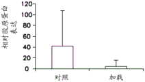
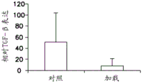
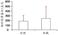
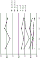
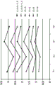
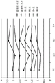
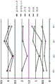
FIGS. 9A and 9B are graphs showing the effect of the static compression loading scheme on (8A) collagen 1 and (8B) TGF- β.
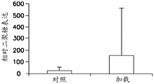
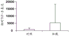
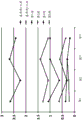
FIGS. 10A-10D are graphs showing the results for (9A) collagen 1, (9B) glycan, (9C) decorin and (9D) TGF-βA graph of the effect of the dynamic compression loading scheme of (1).
11A-11C are illustrations of patterns of indicia to measure displacement of a silicone film by stretching when the embodiments are applied to a film used as a skin model and the displacement of the film when the embodiments are applied.
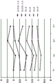
Fig. 12 illustrates a graph showing an evaluation for lack of skin smoothness.
Fig. 13 illustrates a chart showing an evaluation of lack of facial skin softness.
Fig. 14 illustrates a graph showing an evaluation of the appearance of pores on facial skin.
Fig. 15 illustrates a graph showing an evaluation for poor facial skin texture.
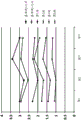
Fig. 16 illustrates a graph showing an evaluation of lack of facial skin clarity.
Fig. 17 illustrates a graph showing an evaluation for lack of facial skin radiance.
Fig. 18 illustrates a chart showing an evaluation of overall facial skin appearance.
Fig. 19 illustrates a graph showing an evaluation of lack of facial skin cleansing ability.
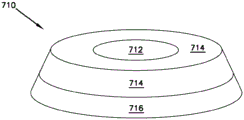
Figure 20 illustrates a cleaning head having a three-dimensional, frusto-conical shape.
Fig. 21A and 21B illustrate components of an embodiment for applying a force with a pin 802 generally perpendicular to the skin in order to displace tissue.
Fig. 22A and 22B illustrate top and side views, respectively, of an embodiment of an articulating feature shape.
Fig. 23A and 23B illustrate top and side views, respectively, of an embodiment of a split alpha blade feature shape.
Fig. 24A and 24B illustrate top and side views, respectively, of embodiments of inverted mushroom features and non-inverted mushroom features.
Detailed Description
Although the present disclosure provides reference to preferred embodiments, workers skilled in the art will recognize that changes may be made in form and detail without departing from the spirit and scope of the invention. Various embodiments will be described in detail with reference to the drawings, wherein like reference numerals represent like parts and assemblies throughout the several views. Reference to various embodiments does not limit the scope of the claims attached hereto. Additionally, any examples set forth in this specification are not intended to be limiting and merely set forth some of the many possible embodiments for the appended claims.
Definition of
As used herein, the term "cleaning head" means an article having a first major surface and a second major surface, wherein the first major surface has a plurality of cleaning features disposed thereon, and the second surface is adapted to be attached to at least an actuator of a cleaning device. In some embodiments, the cleaning head comprises two or more discrete cleaning head sections, each section comprising a plurality of cleaning features. In some such embodiments, one or more cleaning head sections are attached to the handle; provided that at least one cleaning head section is attached to be moved by the actuator. In some embodiments, the cleaning head first major surface is substantially planar. In other embodiments, the cleaning head has a curvilinear or arcuate shape, including a hemispherical shape in some embodiments. In some embodiments, the cleaning head is generally symmetrical; in other embodiments, the cleaning head includes one or more asymmetric portions or asymmetric profiles. In some embodiments, the cleaning head comprises a plurality of arcuate shapes.
As used herein, the term "cleaning feature" means a protrusion that is attached to and extends away from the first major surface of the cleaning head in a direction that is generally perpendicular to the first major surface of the cleaning head. There are between 2 and 100 cleaning features per square centimeter of the first major surface. The cleaning features have an aspect ratio (width: height) of 1:5 to 10:1, where the width or x-distance is the longest dimension of the base (the portion of the cleaning feature that intersects the first major surface of the cleaning head) and the height or y-distance is the distance between the base and the peak (the portion of the cleaning feature that is furthest from the first major surface). The cleaning feature is an elastomeric cleaning feature, i.e., it is formed of an elastomeric composition and is capable of elastic deformation to some extent. The shape of the cleaning features is not particularly limited. In some embodiments, more than one cleaning feature shape, relative cleaning feature orientation, or both are located on a single cleaning head. In some embodiments, more than one cleaning feature shape, relative orientation, or both are located on a single cleaning head section.
As used herein, the term "total displacement" means the maximum linear distance traveled by the motion of a first cleaning head segment relative to a second, adjacent cleaning head segment, as measured at two adjacent points, such as at two points on opposite sides of its adjacent edge. In a sinusoidal oscillating motion, the displacement traveled at the peak of the amplitude is measured relative to the stationary adjacent cleaning head section to obtain the total displacement. Wherein the adjacent stationary cleaning head section also oscillates and the total displacement is a result of the resultant motion of the sections.
As used herein, the term "handle" or "handle portion" means the portion of the cleaning device that fits an average human grip in a manner that enables a user to actuate the cleaning head of the device toward the user's face and maneuver the device to slide the cleaning head across the facial surface. The handle also includes a motor and associated wiring, supports, and power inputs to cause power to be applied to the motor via DC or AC/DC. In some embodiments, the handle includes a switch for turning on or off power to the motor or the device control module. In some embodiments, the handle includes additional controls.
As used herein, the term "elastomer" or "elastomeric composition" means a thermoplastic or thermoset polymeric composition having a fully reversible strain of about 5% -700%, a shore a hardness of about 10 to 50, and a coefficient of friction against human facial skin of about 0.2 to 0.8 (e.g., about 0.25 to 0.75). In some embodiments, the elastomeric component includes one or more fillers, cross-links (crosslinks), or both. Examples of suitable polymers for use in the elastomeric composition include silicone rubber (polydiorganosiloxanes), rubbery polyurethanes, styrene-butadiene rubber (SBR), butyl rubber (butyl rubber), natural or synthetic polyisoprene, nitrile rubber (butadiene-acrylonitrile rubber), rubbery polypropylene, EPDM (ethylene propylene diene copolymer), EPM (ethylene propylene copolymer) and others and blends and copolymers thereof.
As used herein, the term "electric motor" means a device powered by electricity so as to generate motion (whether rotary, reciprocating, orbital, or otherwise) that can be directly or indirectly coupled to a cleaning head or cleaning head segment to cause the cleaning head or cleaning head segment to move as described herein.
As used herein, the term "about" used in describing embodiments of the present disclosure modifying, for example, amounts, concentrations, volumes, process temperatures, process times, throughput, flow rates, pressures, and the like of components in the ingredients and ranges thereof, refers to changes in numerical quantities that can occur, for example, through typical measurement and processing procedures used to make compounds, ingredients, concentrations, or use formulations; through inadvertent errors in these procedures; by differences in the purity of the manufacturing, source or starting materials or components used to perform the method, and similar approximation considerations. The term "about" also encompasses different amounts due to aging of a formulation or mixture having a particular initial concentration, and different amounts due to mixing or processing of a formulation or mixture having a particular initial concentration. Where modified by the term "about," the appended claims include equivalents to these amounts.
As used herein, the word "substantially" used in describing the type or amount of a component, property, measurable amount, method, location, value or range in an embodiment of the present disclosure refers to a change in the component, property, amount, method, location, value or range thereof that does not affect the overall stated component, property, amount, method, location, value or range thereof in a manner that would negate the intended effect of the component, property, amount, method, location, value or range. By way of non-limiting example only, the desired properties include elasticity, modulus (modulius), hardness, and shape; the expected position includes a position of the first cleaning feature relative to the second cleaning feature. Where modified by the term "substantially", the appended claims include equivalents to these types and amounts of material.
Cleaning device
Disclosed herein is a cleaning device for cleaning the skin of a mammal, such as a human, comprising at least one handle; an electric motor disposed within the handle and attached to the actuator, the motor and actuator adapted to apply an oscillating motion at a frequency of about 5Hz to 30 Hz; and a cleaning head having a first major surface and a second major surface, the first major surface comprising a plurality of elastomeric cleaning features extending away from the first surface and having an aspect ratio (width: height) of about 1:5 to 10:1, wherein the cleaning head is divided into two or more cleaning head sections, and wherein an actuator is attached to the second major surface of the cleaning head to apply an oscillating motion to one or more cleaning head sections to cause a total displacement of about 0.5 mm to 8 mm per oscillation.
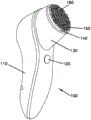
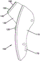
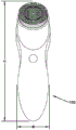
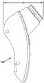
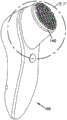
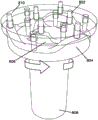
Fig. 1A, 1B are representative views of one exemplary embodiment of a cleaning device. A cleaning device 100 is shown in FIG. 1A, wherein the device 100 includes a handle portion 110, an on/off switch 120, and a mounting portion 130 that positions and secures a cleaning head 140. The cleaning head 140 first major surface 150 includes cleaning features 160. In various embodiments, the handle portion 110 includes a motor (not shown) that actuates selected movement of the cleaning head 140 or a section thereof. A second major surface (not shown) of the cleaning head 140 is attached to an actuator (not shown) in a manner that facilitates actuation of the oscillating motion. Fig. 1B shows a recharging port 170 configured to receive a charger cable (not shown) to provide power to a rechargeable battery device inside the handle portion 110, for example, from a 120V wall plug. The battery arrangement provides electrical power to a motor and control module that actuates movement of the cleaning head 140 or one or more sections thereof.
Fig. 1C and 1D show representative dimensions of the cleaning device. In the illustrated embodiment, the height H of the device is between about 140 mm to 220 mm or about 170 mm to 180 mm. The width W of the device is about 30 mm to 70 mm, or about 40 mm to 60 mm. The depth D of the device is about 50 mm to 120 mm, or about 70 mm to 100 mm.
Various other configurations of embodiments of the cleaning device 100 are contemplated. Some of these embodiments are described in more detail below.
The cleaning head of the cleaning device is an article having a first major surface with a plurality of cleaning features disposed thereon and a second major surface. At least some portions of the cleaning features are formed from an elastomeric composition. In some embodiments, the cleaning head, including all cleaning features, is formed from an elastomeric composition. In other embodiments, the cleaning head is a composite construction having an elastomeric component as a portion thereof, wherein the portion includes at least a surface of the first major surface of the cleaning head and at least a portion of the cleaning feature. The elastomeric composition is a thermoplastic or thermoset polymer composition having a fully reversible strain of at least about 5% -1000%, a shore a hardness of about 10 to 50, and a coefficient of friction (μ, composition-affected properties) against human facial skin (in the absence of beard or similar large amounts of facial hair) of about 0.20 to 1.20. In embodiments, the reversible strain is at least 100% or 200%, and up to 1000%, such as about 700% or about 500%. In an embodiment, the shore a hardness is about 20 to 40. In embodiments, the coefficient of friction against human facial skin is about 0.20 to 1.20 or about 0.20 to 1.00, or about 0.20 to 0.90, or about 0.20 to 0.80, or about 0.25 to 0.75, or about 0.30 to 1.00, or about 0.40 to 0.90, or about 0.40 to 0.80, or about 0.50 to 1.00, or about 0.50 to 0.90, or about 0.30 to 0.80.
Examples of suitable polymers for use in the elastomeric composition include cross-linked silicone rubber (polydiorganosiloxane, specifically polydimethylsiloxane), rubbery polyurethane, styrene-butadiene rubber (SBR), butyl rubber (butyl rubber), natural or synthetic polyisoprene, nitrile rubber (butadiene-acrylonitrile rubber), rubbery polypropylene, EPDM (ethylene propylene diene copolymer), EPM (ethylene propylene copolymer), and others and blends and copolymers thereof. In some embodiments, the elastomeric component is a crosslinked network. In some embodiments, the elastomeric component includes one or more fillers, plasticizers, or both. In some embodiments, the elastomeric component further includes one or more colorants, heat stabilizers, UV stabilizers, antimicrobial agents, and the like.
One example of a suitable elastomer composition is a silica-filled silicone elastomer, such as Dow Corning Co., Midland, Mich. (Dow Corning Co., Midland, Mich.); momentive Performance Materials Inc. of Columbus, OH (Michigan high New Materials group of Columbus, Ohio); those sold by Wacker Chemie AG (Wacker Chemie Co., Ltd.) of Munich, Germany and Shin-Etsu Chemical Co. Ltd. (Shin-Etsu Chemical Co., Ltd.) of Tokyo, Japan. Suitable silicone elastomer compositions include SUPERSIL sold by Mouldlife of Suffolk, KK, two part filled silicone elastomers, and SYLGARD-184, 10:1 two part mixtures sold by DOW CORNING Corporation of Midland, Mischigan. Other suitable elastomeric polymers useful in forming the elastomeric component include rubbery or thermoplastic polyurethanes sold by Bayer materials science AG (Bayer materials science, Inc.) of Leverkusen, Germany, Huntsman International LLC of Woodlans (Wood, Tex.), and others.
In some embodiments, the elastomeric composition includes one or more additives. The additive is embedded within the cleaning head or cleaning head surface to provide additional beneficial results to the user during use of the cleaning device. In some embodiments, the additive is permanent, i.e., it does not deplete from the surface of the cleaning head during use. In other embodiments, the additive is a fugitive additive; i.e. it is depleted during use. Examples of additives include abrasive particles embedded at least within the cleaning feature for skin exfoliation or microdermabrasion, or to adjust the level of static friction or stick-slip of the cleaning feature relative to the skin surface. Such additives are suitably permanent or fugitive, as determined by the manufacturer. Examples of suitable fugitive additives include inorganic and organic molecules beneficial to the skin, which allow the user to care for the skin during cleansing. Examples of such molecules include magnesium, calcium, vitamins such as vitamin D, plant-derived skin active ingredients, antioxidants, and the like. Another example of a fugitive additive is a skin cleansing composition that is embedded within or surrounds the cleansing feature or the cleansing head or a portion thereof.
In some embodiments, a portion or all of the one or more cleaning heads are consumable items that are expected to be frequently replaced, i.e., disposable cleaning heads. For example, in embodiments in which one or more fugitive additives are provided as part of one or more cleaning heads, a suitable time to replace one or more cleaning heads is when the fugitive additives are depleted. In some such embodiments, there are one or more indicators on the cleaning head to indicate when the fugitive additive is exhausted and a new cleaning head is needed. One illustrative example of a suitable indicator is a colored layer disposed below the fugitive additive layer such that the depletion of the fugitive additive is indicated by exposure of the colored layer to the user's sight. Other such indicators are readily envisioned by those skilled in the art. In some embodiments, after a specified period of time, the manufacturer provides instructions to the user to replace the cleaning head in order to ensure that the user uses a cleaning head with a sufficient amount of one or more fugitive additives. In some embodiments, one or more on-board electronic indicators are used to inform the user that it is time to change the cleaning head.
Another example of a useful additive is an antimicrobial composition. Depending on the nature of the additive, useful antimicrobial ingredients are either permanent or fugitive. For example, silver or silver (Ag) components. In some embodiments, the silver composition is a particle. One type of useful silver compositions is BIOMASTER TD100 available from ADDMASTER Ltd. of Stafford (Steford cottoni), UK. When present, the silver component is dispersed in the elastomeric composition employed in forming the first major surface of the cleaning head at about 0.001 wt% to 5 wt% based on the weight of the elastomeric composition or at about 0.01 wt% to 1 wt%, or about 0.05 wt% to 0.5 wt% based on the weight of the elastomeric composition.
In some embodiments, the cleaning features are integral with the cleaning head or cleaning head section, i.e., the cleaning head or cleaning head section having a plurality of cleaning features is a single article formed by molding, 3D printing, or the like. In other embodiments, the cleaning head or cleaning head section is a composite construction having at least one surface layer comprising an elastomeric composition, the surface layer being disposed on at least the first major surface and comprising the cleaning features. In some such embodiments, the cleaning head includes a rigid layer proximate the first major surface. The rigid layer is composed of one or more non-elastomeric thermoplastic materials, thermoset materials, metals, and combinations thereof, such as poly (ethylene terephthalate), acrylonitrile butadiene styrene, polycarbonate, nylon, aluminum, steel, glass, combinations thereof, and the like. In some such embodiments, the rigid layer forms the second major surface.
The shape of the cleaning features is selected from one or more of a variety of shapes as will be described in detail below. In some embodiments, more than one cleaning feature shape, relative cleaning feature orientation, or both are located on a single cleaning head or cleaning head segment.
The cleaning features are protrusions attached to and extending away from the first major surface of the cleaning head in a direction generally perpendicular to the first major surface. In some embodiments, the cleaning feature is integral with the first surface of the cleaning head or cleaning head section; i.e., the cleaning head or cleaning head segment including the cleaning features disposed thereon, is a single molded or formed article or portion thereof. In various embodiments, the cleaning features have an aspect ratio (width: height) of about 1:5 to 10:1, where the width or x-distance is the longest dimension of the base (the portion of the cleaning feature that intersects the first major surface of the cleaning head) and the height or y-distance is the distance between the base and the peak (the portion of the cleaning feature that extends furthest from the first major surface). In some embodiments, the cleaning feature aspect ratio is about 1:5 to 5:1, or about 1:4 to 4:1, or about 1:3 to 3:1, or about 1:3 to 2:1, or about 1:3 to 1: 1. In some embodiments, the aspect ratio of each cleaning feature is variable across a single cleaning head or section thereof.
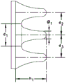
In some embodiments, there are about 2 to 100 cleaning features per square centimeter, or about 3 to 70 cleaning features per square centimeter, or about 5 to 50 cleaning features per square centimeter over at least an area of the cleaning head. In some embodiments, the space between the cleaning features or the "land area" of the first major surface of the cleaning head or cleaning head section is about 1% to 50% of the total first major surface area of the cleaning head, or about 5% to 30% of the first major surface area of the cleaning head. In some such embodiments, the cleaning features are spaced apart so as to be distributed substantially equidistantly on the first major surface in one or more directions. In some embodiments, the cleaning features are spaced apart at a uniform spacing on the first major surface. In some embodiments, the cleaning features are irregularly spaced apart on the first major surface. In some embodiments, the footprint of the substrate of the cleaning feature is about 0.1 mm to 10 mm along the longest dimension, or about 0.5 mm to 8 mm, or about 1 mm to 6 mm, or about 2 mm to 5 mm along the longest direction. In some embodiments, the peaks or heights of the cleaning features extend from about 0.5 mm to 5 mm from the base, or from about 1 mm to 4 mm, or from about 1 mm to 3 mm from the base. To impart to the skin a different stretch-slip action described below than that imparted by bristles used on some skin care devices, the cleaning features have a substantially continuous contact surface with the skin of about at least 1 square millimeter or greater, for example about 1 to 5 square millimeters. This area, which is significantly larger than the skin contact area of a conventional single bristle, is useful for applying stretch-slip forces to the skin as described below.
The shape of the cleaning features is not particularly limited, except that in many configurations, the peak footprint area is the same or less than the substrate footprint area of the individual cleaning features. Benefits of this arrangement include ease of manufacture and a more secure anchoring of the cleaning features on the first surface of the cleaning head or a section thereof during use of the device. Cleaning feature shapes useful in the device include cones, truncated cones, cones (the substrate having a triangular shape), truncated cones, cylinders, hemispheres, prisms (triangular prisms with a rectangular or square base), truncated prisms, cubes, pentahedrons (the substrate having a rectangular shape), truncated pentahedrons, and variations and modifications thereof. In some embodiments, the substrate of the cleaning feature has an "x" shape, a "v" shape, a "y" shape, a "u" shape, a star shape, a crescent shape, a ring shape, or some other shape, and the peak occupancy region reflects that shape; in some such embodiments, the peak footprint is slightly smaller than the base footprint. In some embodiments, the base footprint has one distinguishable shape and the peak footprint has a different distinguishable shape. For example, in some such embodiments, the base of the cleaning features are hexagonal and the peaks are hemispherical.
The irregular shapes and variations in shape set forth above include elongated prismatic features having notches in one or more locations at the peaks; mushroom-shaped (a generally cylindrical base portion having a solid or hollow hemispherical or frustoconical peak portion with its larger dimension facing the first major surface of the cleaning head or portion thereof), inverted mushroom-shaped (a generally cylindrical base portion having a solid or hollow hemispherical or frustoconical peak portion with its smaller dimension facing the first major surface of the cleaning head or portion thereof), tapered features that curve as the features progress from the base portion to the peak portion, in some cases forming a hook-like profile; and other variations as contemplated by those skilled in the art.
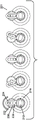
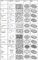
Some examples of cleaning features and their distribution over the first surface of the cleaning head are shown in figure 2. Shape design 1 ("α blade") is a prismatic shape with a rectangular base footprint and a blade-like peak footprint, where the distribution of the α blade features on the cleaning head or cleaning head section is provided by a first set of three cleaning features in a single, even parallel orientation, then the second set of three cleaning features is at a 90 ° orientation from the first set of three cleaning features. Shape design 2 ("latch") is a curved cone shape with a circular base footprint and a smaller circular peak footprint, where its distribution over the cleaning head or cleaning head section is provided by a first row of features in which the cone shape curves in a first direction and a second row of features in which the cone shape curves in a second direction that is approximately 180 ° from the first direction. Shape design 3 ("crowned wave latch") is a different curved conical shape with a rectangular peak footprint, wherein its distribution over the cleaning head or cleaning head section is similar to that of shape design 2. Shape design 4 ("blade tip latch") is similar to shape design 2 except that the peak footprint has a rectangular shape. The distribution of the shape 4 over the cleaning head or cleaning head sections is similar to the distribution of the shape 2. Shape 5 ("α latch concentric row inlay (chase)") is the same shape as shape 2, but the direction of the curved portion of the tapered shape is somewhat randomized; in addition, the overall spatial arrangement of features on the cleaning head or cleaning head section is concentric and not in straight rows.
With continued reference to fig. 2, shape 6 ("blade tip latch nest") is the same as shape 4, but the direction of the curved portion of the tapered shape is somewhat randomized over the cleaning head or cleaning head section; in addition, the overall spatial arrangement of features on the cleaning head or cleaning head section is concentric and not in straight rows. Shape 7 ("concentric blades") is the same shape as shape 1, with a set of 3 alignment features arranged in a concentric pattern. Shape 8 ("inverted mushroom") is a frustoconical feature mounted on a cylindrical portion or stem. The features are arranged in a hexagonal close packed (hexagonal packed) arrangement on the cleaning head or cleaning head portion. Notably, the frustoconical portion of shape 8 is sufficiently flexible so that it can be inverted. Shape 9 ("link") is a crescent shape with a lobed peak footprint. The features are arranged in a staggered manner on the cleaning head or cleaning head portion; the staggered features are arranged in rows on the cleaning head or cleaning head portion. Shape 10 ("non-inverted mushroom") is the same as shape 8, but lacks flexibility so as to not invert to create the mushroom shape. Shape 11 ("split α blade") is the same as shape 1 except that the prism has a peak footprint with notches. The configuration of shape 11 on the cleaning head or cleaning head portion is configured in the same manner as shape 1.
In some embodiments, the cleaning head is divided into two or more discrete cleaning head sections, each section comprising a plurality of cleaning features. The cleaning head section is formed by a discrete partition of the cleaning head at least at the first major surface thereof, the partition extending towards the second major surface. In some embodiments, the cleaning head is divided through its entire thickness, i.e., from its first major surface to its second major surface. The cleaning head section allows movement of the one or more sections by one or more motors activating one or more actuators via connection of the second primary cleaning head surface with the handle portion of the cleaning device. The skin stretching motion is imparted by the interaction of the cleaning features with the skin during movement of the one or more cleaning head sections while maintaining contact with the skin.
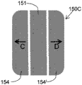
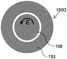
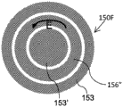
A representative embodiment of a cleaning head design designed to provide skin stretching motion is shown in fig. 3A-3F. Those skilled in the art will envision many other shapes and configurations that achieve similar displacement motion of one or more cleaning head sections. In fig. 3A-3F, the first major surface configurations 150A-150F are variations of the cleaning head first major surface 150 of fig. 1. The arrangement of figures 3A-3F is shown without the cleaning features to illustrate details of the cleaning head section arrangement and selected movement thereof relative to each other. In each embodiment, a first half of the oscillating movement is shown by an arrow, wherein a second half of the oscillating movement (not shown) is in a direction opposite to the direction indicated by the arrow. All movements shown by the arrows are simultaneous in each of the individual embodiments shown in fig. 3A-3F. Fig. 3A illustrates a first embodiment 150A including stationary sections 151 positioned on either side of a first linear motion section 152 moving in a first linear direction a. Fig. 3B illustrates a second embodiment 150B including first linear motion segments 152 moving in a first linear direction a alternating with proximate second linear motion segments 152' moving in a second linear direction B. This relative motion of two proximate segments is referred to as "counter-oscillation" in some embodiments. Fig. 3C illustrates a third embodiment 150C that includes a first lateral motion section 154 and a second lateral motion section 154 'on either side of the stationary section 151, and wherein the first lateral motion section 154 moves in a linear direction C and the second lateral motion section 154' moves in a linear direction D. Fig. 3D illustrates a fourth embodiment 150D, which includes a circular moving section 156 that moves in a counterclockwise direction E and is positioned within the annular stationary section 153. Fig. 3E illustrates a fifth embodiment 150E that includes a circular motion segment 156 that moves in a counterclockwise direction E and is positioned within an annular motion segment 156 that moves in a clockwise direction F. This counter-rotation of two closely circular or annular segments is referred to in some embodiments as "counter-oscillation". Fig. 3F illustrates a sixth embodiment 150F, which includes an annular stationary section 153, a circular stationary section 153 ', and an annular moving section 156 "moving in a counterclockwise direction E, the annular moving section 156" being disposed between the annular stationary section 153 and the circular stationary section 153'.
Those skilled in the art will appreciate that reverse-oscillatory type motion, such as in embodiments 150B and 150E of fig. 3B and 3E, respectively, results in two different types of motion boundaries. As used herein, the term motion boundary means the outer edge of a moving cleaning head or cleaning head segment as shown in fig. 3A-3F. There is a moving boundary at the edge of each moving cleaning head section. Referring to 150B, at the edge of 152 near the edge of 152', the counter-oscillation sets the relative motion boundary 157, while the motion boundary 158 is a simple motion boundary. Similarly, the counter-oscillation of the reference embodiments 150E, 156 'provides a relative motion boundary 157', while the oscillation of 156 'sets a simple motion boundary 158'.
As described above, each of the embodiments 150A-150F in fig. 3A-3F shows a first half of the oscillating motion, with a second half of the oscillating motion in a direction opposite to the direction indicated by the arrow. When the cleaning device is turned on, the oscillating movement is repeated as a series of cycles, which continue until the device is turned off. The oscillating motion is a skin-stretching motion when the cleaning features disposed on the cleaning head 150 are held against the skin. The skin-stretching movement is particularly beneficial within certain defined parameters. Fig. 4A-5B provide additional details of this motion, particularly with respect to the embodiment 150A of fig. 3A and the embodiment 150D of fig. 3D, respectively, to illustrate these parameters. Referring to example 150A, at the start of oscillation, points x and y are separated by about 0.5 mm to 8 mm. Midway through one oscillation 150A', the first linear motion section 152 has moved in the first linear direction a, with points x and y aligned; thus, the section 152 has moved 0.5 mm to 8 mm relative to the stationary section 151. The first linear motion section 152 now moves in the opposite direction until the cleaning head returns to its original configuration 150A, completing an oscillation.
It will be appreciated that in some configurations the first linear motion section 152 is moved in a manner that causes it to oscillate equally on both sides from the position indicated by 150A, i.e. half of the total displacement distance is indicated by 150A 'and 150A-150A' represents a quarter of a cycle rather than half, and in embodiment 150A, points x and y are separated by approximately 1 mm to 4 mm. It will also be appreciated that for two adjacent moving cleaning head sections, such as the representations 150B of fig. 3B and 150E of fig. 3E respectively, the total displacement distance must take into account the movement of the two moving sections. In some such embodiments, each moving cleaning head section moves half of the total displacement distance in each cycle.
Similar to examples 150A-150A ', examples 150D-150D' show that at the beginning of oscillation, points x and y are displaced along line z by 0.5 mm to 8 mm apart. Midway through one oscillation 150D', the circular motion segment 156 has moved in the counterclockwise direction E, with points x and y aligned; thus, the movement of the circular section 156 has displaced the point y by 0.5 mm to 8 mm. The circular motion segment 156 now moves in a clockwise direction until it returns to its original configuration 150D, thereby completing an oscillation.
Some other embodiments oscillation of the cleaning head configuration (e.g., the other configurations shown in fig. 3A-3F) are similar to those of fig. 4A-5B. The total displacement per cycle of each moving cleaning head section relative to the adjacent moving cleaning head section(s) or relative to the adjacent stationary cleaning head section is about 0.5 mm to 8 mm. In some embodiments, the displacement per cycle is about 1 mm to 8 mm, or about 2 mm to 7 mm, or about 2 mm to 6 mm, or about 2 mm to 3 mm, or about 3 mm to 5 mm, or about 3 mm to 4 mm. Additionally, the cycle frequency (time per cycle) is about 5Hz to 30Hz, or about 10 Hz to 30Hz, or about 15Hz to 30Hz, or about 20 Hz to 30Hz, or about 25 Hz to 30Hz, or about 5Hz to 25 Hz, or about 5Hz to 20 Hz, or about 5Hz to 15Hz, or about 10 Hz to 30Hz, or about 10 Hz to 25 Hz, or about 10 Hz to 20 Hz.
It will be understood that the various configurations of the cleaning head, particularly with respect to the number and configuration of cleaning head sections, are not particularly limited and are selected by the designer. Thus, in some embodiments in which a circular central cleaning head section is surrounded by a counter-oscillating ring, 1 to 3 annular cleaning head sections, or 2 to 5, or even 5 to 100 annular cleaning head sections are arranged on the cleaning head in concentric circles, with the counter-oscillating action being provided by an alternating oscillating motion of the concentric annular cleaning head sections. In one example, a single annular cleaning head section includes a single row of cleaning features arranged radially about the annular section. The segments can counter-oscillate, or the oscillating segments can alternate with the stationary segments, or a combination thereof. Similarly, the linear oscillating cleaning head section is not specifically limited by the total number of counter-oscillating or alternating stationary/oscillating sections.
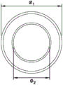
In some embodiments, the cleaning head is divided into two cleaning head sections, including an inner circular section and an outer annular section, wherein one of the sections is adapted to be substantially stationary during operation of the cleaning device while the other section moves in an orbital motion. The orbital motion follows a circular or elliptical path without any circular (rotational or torsional) displacement. In such an embodiment, the movement gap formed between the inner circular section and the outer annular section provides a displacement of about 0.5 mm to 8 mm. In some embodiments, the outer annular section is stationary and the inner circular section moves in an orbital manner at a frequency of 5Hz to 30Hz to provide a displacement between the inner and outer sections of 0.5 mm to 8 mm. In other embodiments, the inner circular section is stationary and the outer annular section moves in an orbital manner at a frequency of 5Hz to 30Hz to provide a displacement between the inner and outer sections of 0.5 mm to 8 mm, and a displacement at the outer periphery of the outer annular section.
In some embodiments, the first major surface of the cleaning head is not divided into cleaning head sections. Instead, in such embodiments, the movement of the cleaning features relative to each other is achieved by moving the elastomeric surface from below. In such embodiments, the cleaning head has a single, continuous elastomeric top layer that supports the cleaning features. The cleaning head first surface is manipulated or stretched from below. In some such embodiments, more complex motion patterns are implemented, such as planetary motion or orbital motion.
Movement of the cleaning head segment is facilitated by a coupled motor actuating movement through attachment of the cleaning head segment to the actuator. It will be appreciated that in some embodiments, the cleaning head is attached to the handle while one or more cleaning head segments are attached to one or more actuators. In some embodiments, one or more cleaning head segments are attached to one or more actuators to provide an oscillating motion, while one or more additional cleaning head segments are attached to the handle to provide one or more stationary cleaning head segments. In other embodiments, one or more actuators provide counter-oscillating motion of two or more cleaning head sections.
Notably, the cleaning apparatus is freely usable by a user without engaging the motor to move the cleaning head or cleaning head section(s). Thus, the user can simply move the cleaning device in a cleaning motion against the skin and achieve a cleaning effect. Additionally, in some embodiments, the cleaning device includes one or more settings allowing the user to take larger or smaller displacements per cycle, larger cycle frequencies such as 30Hz to 100 Hz, or a combination of such variable displacements and frequencies to accomplish specific tasks such as deep cleaning or exfoliation.
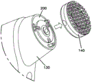
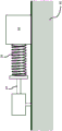
With respect to the interaction of the cleaning head with the actuator, an exemplary embodiment will now be discussed in detail to provide an understanding of one possible mechanism for the oscillating motion. Referring to fig. 1E, the cleaning head 140 and its attachment to the cleaning device 100 is shown in somewhat more detail. FIG. 1F illustrates an enlarged view of the cleaning device of FIG. 1E. In particular, fig. 1F illustrates the cleaning head 140 as removable from the cleaning device 100, thereby showing features of the actuator mechanism 200.
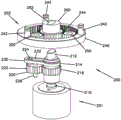
Fig. 1G is a partially exploded view of the actuator mechanism 200, including features disposed within the handle 110 of the cleaning device 100. The actuator mechanism 200 comprises a primary drive 201 and a secondary drive 202. The primary drive 201 includes a motor drive shaft 210, a gear mechanism 220, and a pivot arm 230. The motor drive shaft 210 includes an engagement member 212, a collar 214, and a collar gear 216. The collar gear 216 is attached to the motor drive shaft 210 and thus moves along with the motor drive shaft 210. The collar 214 and the engagement member 212 are attached to each other, but not to the motor drive shaft 210, and thus the collar 214 and the engagement member 212 are able to move in a rotational manner independently of the motor drive shaft 210 and the collar gear 216. The gear mechanism 220 includes a gear 222, an offset pin 224 (extending upward from the gear 222 in fig. 1G), and a center pin 226 (extending downward from the gear 222 in fig. 1G). The gear 222 is engaged with the collar gear 216 and is held stationary in space by the center pin 226 (i.e., the center pin 226 is engaged with a stationary member, not shown). The pivot arm 230 is attached to the collar 214 and supported by the collar 214 and includes a slot 232 that slidably engages the offset pin 224. The secondary drive 202 includes an outer ring gear 240, planet gears 250, and a sun gear 260. The outer ring gear 240 includes engagement pins 242. The sun gear 260 includes an engagement slot 262 adapted to receive the engagement member 212. The sun gear 260, planet gears 250, and outer ring gear 240 combine to form a planetary gear system.
When the engagement member 212 is operatively engaged with the engagement slot 262, the primary drive 201 and the secondary drive 202 are operable to provide counter-oscillatory motion by moving the collar gear 216 through rotational motion of the motor rotary shaft 210. This movement is illustrated in fig. 1H and 1I. Fig. 1H is a top down view of the primary drive 201. One complete cycle of movement of the primary drive 201 driven by the motor-shaft-ring gear 216 is shown from left to right in figure 1H. Movement of the shaft 210 moves the collar gear 216 in a clockwise direction. Movement of gear 222 in the counterclockwise direction occurs through engagement of collar gear 216 with gear 222. Rotation of gear 222 causes movement of biasing pin 224 within slot 232, thereby causing movement of pivot arm 230 first in a counterclockwise direction, then clockwise, then counterclockwise, as shown by the series configuration from left to right in fig. 1H. In some embodiments, the arcuate motion of the pivot arm 230 as shown in FIG. 1H may extend through an arc from about 20 to 50, or from about 25 to 45, or from about 30 to 40, over a single complete cycle. As described by the pivot arms 230, the engagement members 212 move simultaneously and over the same arc. Fig. 1I is a top down view of the movement of the secondary drive 202 when the engagement member 212 of the primary drive 201 is engaged within the engagement slot 262. One complete cycle of movement of the primary drive means 202 driven by an actuator engaged with the primary drive means 201 is shown from left to right in figure 1I. Dashed lines are provided to add perspective views regarding the relative movement of the sun gear 260 and the pin 242 attached to the outer ring gear 240. Movement of the sun gear 260 engaged with the planet gears 250 acts to move the outer ring gear 240 in a direction opposite to the movement of the sun gear 260, as shown by the movement of the pin 242. As shown in FIG. 1I, the motion of the outer ring gear 240 over a single complete cycle traverses an angle from about 5 to about 30, or from about 7 to about 25, or from about 10 to about 20.
Thus, the design of a cleaning head that is fitted to work in conjunction with the actuator mechanism 200 of FIG. 1G includes: an annular outer cleaning head section adapted and designed to engage with the pin 242 of the secondary drive 202, and an inner circular cleaning head section adapted and designed to engage with the hub of the engagement slot 262. As shown in fig. 1G, the collar gear 216 on the primary drive 201 is connected to a DC motor. The action of the motor rotating shaft 210 and the collar gear 216 movement in either the clockwise or counterclockwise direction causes the described movement and is shown in fig. 1H and 1I. Movement of the hub of the moving engagement slot 262 when engaged with the moving engagement member 212 of the primary drive 201 moves the circular inner cleaning head section in a first direction (counterclockwise as shown in fig. 1H) and then counterclockwise; simultaneously, movement of the pin 242 moves the annular outer cleaning head section in a second direction (clockwise as viewed in fig. 1I). In this way, a radial counter-oscillating movement is achieved. Other embodiments not specifically limited by the description of the exemplary embodiments provided herein will occur to those skilled in the art and do not depart from the spirit and scope of the appended claims.
The handle portion of the device houses a motor, which is powered either directly from an AC/DC power source or from a battery. The handle also includes associated wiring, supports, and power inputs to facilitate application of power to the motor via DC or AC/DC. If powered directly, a power cord (cord) is provided that allows the user to plug the cleaning device into a standard wall outlet (e.g., 120V, 60Hz in North America) and convert the power to DC. If the cleaning device is powered by batteries, a recharging power cord is removably attached to the device, and the recharging power cord is plugged into a standard wall outlet in order to recharge the depleted batteries. In some embodiments, where the device is battery powered and rechargeable, a sensor visible to the user is coupled to a display, wherein the user is alerted as to the condition of the remaining battery power. In some embodiments, the handle includes a switch that is available to a user to turn power to the motor on or off.
In some embodiments, the cleaning device also houses a timer that beeps, vibrates, or otherwise notifies the user that a particular increment of time has elapsed. For example, a timer algorithm that causes a beep signal to sound every 15 seconds, or every 30 seconds, or some other interval when the cleaning device is turned "on" may be useful to alert the user that he or she should begin cleaning different areas of skin. It is useful to employ a timer interval in conjunction with an automatic "off" switch housed internally that turns off the device after a certain number of timed intervals. For example, in some embodiments for facial cleaning, a timer routine is implemented that oscillates once every 15 seconds, and after four 15 second intervals (during which the timer oscillates three times), the device automatically shuts down. In some embodiments, the user can select (via a control device located on the handle) a skin cleansing program in which the timer and automatic shut down are programmed for facial cleansing, mild facial cleansing, foot cleansing, and the like.
In some embodiments, the cleaning device is waterproof and can withstand immersion in water of up to 0.25 meters, up to 1 meter, up to 2 meters, or more, for example, without water entering a handle or other portion of the device housing the electrical components. In other embodiments, the cleaning device is water resistant, i.e., capable of washing or splashing the device without water entering the handle or other portion of the device housing the electrical components, but incapable of submerging the device without water entering the handle or other portion of the device housing the electrical components.
The handle portion fits in an average human grip in a manner that enables a user to comfortably place the first major surface of the cleaning head in contact with the user's face with some applied pressure, and to manipulate the device to slide the cleaning head across the face surface. Although the embodiment shown in fig. 1A and 1B is not limiting as to the type of handle design that is usefully employed with the cleaning apparatus, it is instructive. The material used to make the handle chassis (i.e., the portion of the handle visible to the user) is not particularly limited. Generally, metal or plastic compounds or combinations thereof are used to form the chassis and the design or functional details present thereon. A common material employed to form the handle portion is acrylonitrile-butadiene-styrene (ABS) copolymer. In the handle portion of the device, antimicrobial agents, colorants, surface finishes, textures, and the like are suitably included.
In some embodiments, the cleaning head, or a portion thereof comprising the first major surface, is removably attached to the cleaning apparatus. In an embodiment, removing the cleaning head is useful for washing or replacing the cleaning head or a part thereof. Various attachment mechanisms are useful for removably attaching the cleaning head, or a portion thereof, to the cleaning device. Examples of useful attachment mechanisms include hook and loop mating attachment surfaces, snaps, latches, screws, and any other such mechanism known to those skilled in the art. In some embodiments, the cleaning head second major surface is disengaged from the actuator to enable (affect) removal of the entire cleaning head. In other embodiments, the removable portion of the cleaning head is an elastomeric member comprising at least a portion of the first major surface, and in some such embodiments, attachment means such as those described above are employed to removably attach the elastomeric member to the cleaning head. In other such embodiments, the elastomeric member is adapted to be stretched to cover and surround at least a portion of the non-removable portion of the cleaning head such that the combination of elastic recovery and stiction of the stretched elastomeric member maintains the position of the elastomeric member on the cleaning head.
In some embodiments of the cleaning device in which a portion of the cleaning head is removable, the cleaning device is advantageous in that the user is not only able to remove the cleaning head or a portion thereof to clean or replace it, but the user is also able to exchange the cleaning features on the first major surface thereof. Thus, in an embodiment, the cleaning device is part of a kit comprising two or more replacement cleaning heads or cleaning head sections in which the cleaning features are different. Such embodiments are described in more detail below.
In some embodiments, the cleaning feature design has the advantage of easy washing of the cleaning head between uses. The high aspect ratio of the cleaning features (no less than 1:5 width: height when compared to bristles, which typically have an aspect ratio of 1:10 or less) imparts cleanability to the cleaning head, wherein residues remaining from cleaning (residual cleanser, dirt, bacteria and dead skin cells) are easily washed away from the surface of the cleaning head. The cleaning head section is therefore more hygienic in the case of repeated use than the cleaning brush. Further, in embodiments where the elastomeric component includes, for example, an antimicrobial compound or particles, the growth of bacteria or other microorganisms on the surface of the cleaning head is slowed or entirely prevented. Thus, the cleaning head of the present invention has superior cleanliness and/or cleanability when compared to brush-based devices.
Control system
The cleaning device has a control system 500 (see fig. 6) that allows the user to turn the device on and off, and in some embodiments, make selections of operating parameters. As can be seen in fig. 6, in one embodiment, the controller 500 has an on-off control 502. Which may have an optional oscillation frequency control 504 and/or oscillation amplitude control 506. The control means may be individual buttons or areas on a touch pad or touch screen (not shown).
The controller circuit 510 has logic circuits or may be a programmed microprocessor, in either case configured to receive various input signals and provide output signals to control components or an optional display. Power for the controller circuit 510 comes from the battery 540, which may be rechargeable, and may have an associated charge level indicator 532. The controller circuit 510 has an input interface that senses a condition of the controllers 502, 504, 506 for use as an input to the control logic. The control logic includes a timer that can be used as a cycle timer for usage cycles or to time other intervals used in the control. In one embodiment, the controller circuit 510 times a long interval that defines a complete usage cycle, such as 2 minutes, 3 minutes, or 5 minutes or any suitable interval of usage. It also times a segment of this full usage cycle at the end of which a brief change in oscillation frequency, beep, or other indication may instruct the user to continue moving to a new treatment zone on the multi-zone skin area to be treated. For example, when treating the face, the facial skin may be subdivided by the device into 2, 3, 4 or more zones to be treated at different times as part of the recommended complete use cycle. Controller circuit 510 may also optionally include a display driver 514 that controls text, images, or other visual signals presented to the user on optional display 530. Alternatively, instead of a visual signal, only an audible signal may be used to provide a signal to the user. In this case, the display 530 is a buzzer or small transducer for generating one or more sounds under the control of the controller circuit 510. In some embodiments, the controller circuit 510 may be configured to generate artificial human speech (e.g., to give voice direction) using a speech synthesizer, pre-recorded content, or other device.
The controller circuit 510 also has a motor interface 520 through which the controller circuit 510 delivers a selected amount of power and/or actuation signals and potentially a mode-changeable power and/or actuation signal to the electric motor 522. In this way, the action of the electric motor can be controlled. The electric motor 522 is operably connected to an actuator 540 that delivers motion to the cleaning surface shown in fig. 3A-4B. The controller 500 and its controller circuitry 510 allow a user to control the operation of the device during use of the device, as described next. Basic control allows the device to be turned on or off. For example, with other control features, the user can control the movement of the cleaning surface in relation to the amplitude of the movement within the ranges discussed above, as well as the control frequency of the oscillations of the cleaning surface within the ranges discussed above, in conjunction with the pressure applied by the user at the cleaning surface shown in fig. 3A-4B, to meet the user's perception of comfort and effectiveness. These two parameters can be controlled independently. There may be differences between users regarding the levels of these parameters that are considered comfortable and/or effective. The device allows the user to control these selections by adjustments, optionally with display 530, where display 530 displays the current parameter adjustment status and provides guidance for making adjustments, such as displaying a graphic of a bar graph with the current level and the range of available adjustments. The display 530 may also display timers for a complete care cycle or for discrete segments.
In some embodiments, as described above, the cleaning device also houses a timer that notifies the user that a particular increment of time has elapsed. For example, a timer that beeps every 30 seconds is useful to alert the user that he or she should begin cleaning different areas of the skin. It is useful to employ a timer interval in conjunction with an internally housed automatic "off" switch that turns off the device after a certain number of timed intervals. A flow chart illustrating one such timing algorithm is shown in fig. 7. The timer algorithm is started by the user activating the cleaning device 610, setting the usage parameters 620, applying the cleaning composition 630 to the device or the user's skin (or the skin of the person whose skin is to be cleaned by the user) and starting the cleaning of the first zone (n = 1) 640. After a predetermined interval, the timer algorithm sends a signal to a mechanism (speaker that causes a musical tone or beep, vibrating element that sends a vibration through the handle, switch that temporarily shuts down the cleaning device, etc.) that alerts the user that the zone cleaning is complete. The user is then alerted to move to the next area of skin for cleaning. After a predetermined number of such time intervals n, sending a signal to the device to shut down; this is accomplished after each zone is completed via a series of interrogations 660. After each signal, n is increased by 1 after each interval until n reaches the target value and the device is shut down.
External member
In embodiments of the cleaning device in which a portion of the cleaning head is removable, it is advantageous that the user not only is able to remove the cleaning head or a portion thereof to clean or replace it, but the user is also able to exchange the cleaning features on the first major surface thereof. Thus, in an embodiment, the cleaning device is part of a kit comprising two or more replacement cleaning heads or cleaning head portions in which the cleaning characteristics are different.
In some embodiments, the kit comprises at least one cleaning device and two or more cleaning heads or cleaning head portions. In some embodiments, the two or more cleaning heads or cleaning head portions are substantially identical; in other embodiments, two or more cleaning heads or cleaning head portions have different cleaning features or different arrangements of cleaning head features disposed thereon. In some embodiments, the kit comprises two or more cleaning heads or cleaning head portions that are substantially identical, and additionally comprises one or more additional cleaning heads or cleaning head portions having different cleaning features or different arrangements of cleaning head features arranged thereon.
In some embodiments, the kit further comprises a power cord for removable attachment to the cleaning device handle and a plug adapted to be received by the power source. In some embodiments, the kit further comprises a docking station (docking station) adapted to secure the cleaning device when not in use. In some embodiments, the docking station includes an adaptor that connects to the cleaning device handle, connecting the device to a power cord having a plug adapted to be received by a power source. In some embodiments, the docking station includes a cleaning mechanism to clean the cleaning head first surface when the cleaning device is secured to the docking station. In some embodiments, the kit further comprises one or more skin cleansing compositions packaged for use with the cleansing device. In some embodiments, the kit further comprises a travel bag adapted to contain the cleaning device to protect the cleaning device during travel, such as in a suitcase or bag.
Alternative kits are also contemplated; such a kit is associated with, but does not include, a cleaning device. The retrofit kit includes a retrofit part or component for a user already in possession of the cleaning device. One such kit includes substantially identical one or more cleaning heads or cleaning head portions. Another such kit includes two or more cleaning heads or cleaning head portions having different cleaning features or different arrangements of cleaning head features disposed thereon. Another such kit includes one or more cleaning heads or cleaning head portions and one or more packages containing a skin cleansing composition; the ingredients are the same or different. Some kits include two or more of the above replacement parts or compositions.
In some embodiments, the kit further comprises one or more sets of instructions to instruct the user how to use the cleaning device, specialized packaging, labels, decorative designs, coupons, and the like.
It will be appreciated that the different cleaning heads or cleaning head portions, whether or not included in the kit, are designed to achieve a variable effect when used by a user; further, in some embodiments, specific cleaning agents may be recommended for use in conjunction with specific cleaning feature designs or arrangements. Thus, different effects ranging from mild massaging to powerful exfoliating are achieved by exchanging the cleansing features and skin cleansing ingredients.
Use of the device
The cleaning device is used for cleaning the skin of the mammal; in particular human skin. In some embodiments, the device is used as a facial skin cleaner for humans. In some embodiments, the device is used to care for the facial skin of a human. The device is intended for use in conjunction with a skin cleansing or treatment composition, such as a detergent-type or non-detergent-type facial skin cleansing composition, or a non-detergent-type treatment composition, such as a moisturizing composition, such as a lotion, gel, cream, or combination thereof. To use the device, the user coats at least a portion of the first major surface of the cleaning head with a skin cleansing or treatment composition (or alternatively applies the composition to an area of skin), brings the device into contact with his or her own face, and activates the device to initiate a skin-stretching motion. The skin-stretching motion of the cleansing features imparts certain surprising and unexpected advantages when used in conjunction with cleansing ingredients.
The skin-stretching motion stretches the skin surface and also the skin cells, allowing for a greater degree of cleaning and/or care without causing pain or discomfort to the user than can be achieved using conventional brush-type skin cleaning equipment. The skin-stretching motion also provides scraping or rolling (squeegee) like a cleaning action. These two observed motions are the combined result of the cleaning characteristics, along with the skin cleanser interacting with the skin surface in an adhesive-slip mechanism when the cleaning device is "turned on" and held against the skin. "stick-slip" can be described as surfaces alternating between sticking to and sliding over each other, and the frictional forces correspondingly change. Typically, the static coefficient of friction (trial number) between two surfaces is greater than the dynamic coefficient of friction. When the applied force is large enough to overcome the static friction, then the decrease in friction from static to dynamic can cause a sudden jump in the speed of motion.
Fig. 8 is a schematic view showing theoretical physical elements of stick-slip behavior. The drive system 10 is connected to the spring 20 and the load 30 rests on a horizontal surface 40. The static friction between the load 30 and the surface 40 is determined by mass (gravity). When the drive system 10 is activated, the spring 20 is loaded and the urging force of the spring 20 against the load 30 is thus increased until the coefficient of static friction between the load 30 and the surface 40 is overcome. At this point, the load 30 begins to slide horizontally across the surface 40 and the coefficient of friction decreases from its static value to its dynamic value. At the moment of the start of the sliding, the spring 20 accelerates the load 30. During movement of the load 30, the force exerted by the spring 20 decreases until the force is insufficient to overcome the dynamic friction of the load 30 on the surface 40. From this moment, the load 30 decelerates and eventually stops. However, the drive system 10 continues to load the spring 20 and when the spring is reloaded, the stick-slip cycle begins again. In systems where the load will oscillate, it is contracted, which can cause stick-slip cycles during the reset motion.
Following the schematic representation of fig. 8, 10 denotes an actuator on the cleaning device which is urged in a first direction by a motor, 20 denotes the elasticity (modulus of elasticity) of the cleaning feature, 30 denotes the cleaning feature which is held against a surface denoted by skin 40, wherein the force urging the cleaning device towards the skin is determined by the user and not by gravity. In this way, static and dynamic friction of the cleaning features against the skin is triggered in a slip-stick mechanism. The static-dynamic friction balance is achieved by the use of selected cleaning agents and/or water, the coefficient of friction of the cleaning features against the skin, and the force with which the user presses the cleaning device against the skin. During the oscillating movement of the cleaning head, the cleaning agent reduces the adhesive portion of the stick-slip action of the cleaning features that are in frictional contact with the skin surface. Thus, depending on the force applied by the user, the stretch caused by the adhesive portion of the stick-slip action of the cleaning feature may be more easily modulated and reduced relative to the nominal total displacement distance in the oscillation cycle.
The adhesive portion of the adhesive-sliding action causes stretching of the skin cells due to the movement of the cleaning feature caused by the cleaning head actuator until the static friction is overcome. Activation of the sliding portion of the stick-slip action then causes the cleaning feature to slip across the skin cell surface. When a skin cleansing composition is added to the first major surface of the cleaning head, the lubricating effect of the liquid interface between the cleansing features and the skin reduces traction during the "glide" portion of the motion, or in some cases also reduces stiction, causing less "stick" and more "glide" during use. Similarly, the pressure exerted by the user of the cleaning feature against the skin during use affects the balance of "stick" and "slip".
In certain embodiments, a method of cleaning and/or treating human skin includes applying a cleaning and/or treatment composition to the skin and/or a cleaning head of a device, contacting the cleaning head with the skin, and activating the device. The user can move the cleaning head of the device across the skin to reach the desired treatment area. In an embodiment, contacting comprises applying a force, such as a force averaging about 1N to 10N, or about 1N to 8N, or about 2N to 6N, or about 2N to 4N, or about 2N to 10N, or about 4N to 10N, or about 2N to 8N, or about 2N to 6N, or about 3N to 5N, or about 4N. In certain embodiments, the applied force may vary based on the desired treatment area (e.g., a relatively light force may be applied to more sensitive facial skin around the user's eyes while a relatively high force may be applied to less sensitive facial skin near the user's cheeks), the coefficient of friction between the cleaning head and the desired treatment area (e.g., as varied by the applied cleaning and/or treatment composition), and other factors.
In certain embodiments, the stick-slip action of the cleaning features during contact and the displacement of the cleaning head further in combination with the applied cleaning and/or conditioning ingredients provides a skin displacement that is about 5% to 100% of the displacement of the cleaning head, or about 5% to 90%, or about 10% to 90%, or about 20% to 90%, or about 25% to 90%, or about 30% to 90%, or about 40% to 90%, or about 50% to 90%, or about 5% to 80%, or about 5% to 70%, or about 5% to 60%, or about 5% to 50%, or about 10% to 70%, or about 20% to 60% of the skin displacement, as determined by measurement of the displacement of the synthetic silicone skin model as described herein in example 2. Thus, for example, if the cleaning head displacement is 5 mm, the skin displacement measured at least at one location is about 0.25 mm to 4.5 mm. Those skilled in the art will appreciate that the variability of skin displacement measured during use of a cleaning head having a known displacement during operation of the cleaning head is caused by the selection of the cleaning and/or conditioning ingredients employed, the shore a hardness and coefficient of friction of the cleaning features, and the force applied during use by the user. The aforementioned variables affect the stick-slip action and thus the actual skin displacement.
Without wishing to be bound by theory, it appears that the "sticky" phase of the cleaning action provides benefits in manipulating the skin by stretching, which cannot be achieved effectively with bristles because its greater aspect ratio and flexibility relative to applicant's cleaning features is not as effective in stretching the skin surface and layers beneath the surface in the manner found to be beneficial. Bristles also appear less suitable for applying scraping forces across an area of skin in a sliding motion. As noted above, bristles tend to pull skin cells but not remove them; therefore, the brush can have an effect of roughening the skin. In sharp contrast, the cleaning action of current cleaning features is effective to remove surface cells via a stick-slip motion, resulting in a skin smoothing effect that is observable by the user. The peak footprint of the elastomeric cleansing features, along with the displacement and frequency of its oscillating action, produces a wiping effect on the skin surface. This action removes loose skin cells, but does not "dig" deep into the stratum corneum to pull and remove other stratum corneum cells. Stated differently, the cleaning features of the cleaning device remove those that are flaccid and rough without increasing the roughness of the skin surface.
Without wishing to be bound by theory, we believe that a particular degree, frequency, or period of controlled stretching of human skin, or a combination of two or more thereof, results in a stretching of the minicell extracellular matrix, which in turn causes a stretching of the attached dermal fibroblasts. We believe that this stretching causes favorable gene expression changes in fibroblasts, directing them to repair or augment the extracellular matrix (ECM) of the skin and improve skin health and appearance. The extracellular matrix is composed of collagen fibers, elastin fibers, and water-retaining molecules (e.g., other proteins and glycosaminoglycans such as chondroitin, glycans, hyaluronic acid, etc.) held within the network of fibers. Restoration of ECM results in an improvement in appearance and a decrease in apparent age of the subject.
Without limitation, various types of skin cleansing compositions are useful in conjunction with the cleansing device. In general, any liquid, dispersion, emulsion, gel, slurry or solution conventionally used for cleansing skin can be used in conjunction with the cleansing device. The preferred method of use is to apply a cleanser to the first major surface of the cleaning head, then bring the first major surface into contact with the skin, and "turn on" the device. However, the user can also apply the cleaning composition to the skin, then bring the cleaning device into contact with the skin, and "turn on" the device. In some embodiments, the detergent cartridge is integrally disposed within the cleaning head and is arranged to dispense a skin cleansing or other ingredient to the skin during use. Other ingredients include, for example, oils or other slip agents to reduce static friction, astringents to treat skin conditions such as acne, medicinal ingredients, and the like. In some embodiments, the cartridge can be refilled by a user. In other embodiments, the cartridge itself is replaced by the user after emptying. In some such embodiments, the cleaning device comprises a sensor adapted to provide a signal to alert a user when the cartridge is empty.
During use, the cleaning device is moved by the user around the surface of the skin. The skin-stretching motion of the cleaning feature acts on the skin and the cleaning composition present on the cleaning feature is present at the interface between the skin and the cleaning feature. The skin-stretching motion is thus coupled with the availability of cleaning elements that can be deposited by the action of the cleaning features into the skin crevices and striae during the "stick" phase of the cleaning action, and then further urged across the skin surface during the "slip" phase of the cleaning action.
Examples of skin cleansing compositions usefully employed in connection with the cleansing device include Deep cleansing (Deep Clean) sold by Neutrogena Corp. (dew corporation) of los angeles, california or Ultra Gentle moisturizing (Ultra crop); cerave facial cleanser sold by Valerant Pharmaceuticals North America LLC of Laval (Laval), Quebeck, Canada; clarisonic cleanser (Clarisonic cleanser) sold by Pacific Bioscience Laboratories Inc., of Redmond, Washington; an avivoro cleanser (Aveeno cleaners) sold by Johnson & Johnson (Johnson, qian) of New Brunswick, New jersey; pure cleanser (pure Cleaner) sold by Philophy Inc. (Nature Philosophy) of Phoenix City, Arizona; facial cleanser sold by Estee Lauder Cos, New York, Arsela; FREE & CLEAR facial cleanser sold by Pharmaceutical Specialties, Inc. (medicinal Specialties, Inc.) of Rochester, Minnesota; or a cleanser such as a bar of soap or liquid soap mixed with water. In embodiments, the cleanser is a non-detergent, non-foaming cleanser. In some embodiments, the skin cleansing ingredient is characterized by the absence of a lauryl sulfate, such as sodium lauryl sulfate or ammonium lauryl sulfate salt. In some embodiments, the skin cleansing ingredient is characterized by the absence of an ionic surfactant. In some embodiments, the skin cleansing ingredient is characterized by a semi-liquid state, i.e., viscous, that is similar to honey and does not undergo substantial shear thinning. In some embodiments, the skin cleansing composition is pumpable and is delivered in a pump bottle. In some embodiments, the skin cleansing composition is characterized by a smooth, silky feel without a tactile impression that is generally like sand or chalk. In some embodiments, the skin cleansing ingredient comprises one or more moisturizers, glycerin, or oils.
Examples of useful components included in the skin cleansing composition include those that do not substantially negate or retard the stick-slip action of the cleansing device during use. In some embodiments, the skin cleansing ingredient comprises water, glycerin, palmityl alcohol, polyglyceryl-10 laurate, ethylhexylglycerin, Cetearyl Glucoside (Cetearyl Glucoside), caprylyl glycol, carbomer, sodium hydroxide, phenoxyethanol. In some embodiments, the skin cleansing composition comprises 0.001% to 4% salicylic acid, or about 0.5% to 3% salicylic acid, or about 1% to 2% salicylic acid by weight. In some embodiments, the skin cleansing ingredient comprises water, sodium cocoyl isethionate, glycerin, sodium C14-16 olefin sulfonate, glyceryl polyether-2 cocoate, glyceryl stearate, sodium methylcocoyltaurate, acrylate copolymers, PEG-18 glyceryl oleate/cocoate, purslane extract, Camellia oleifera leaf extract, witch hazel (witch hazel) water, lotus extract, panthenol, butylene glycol, tetrahexyldecanol ascorbate, allantoin, tocopheryl acetate, hydroxyphenylpropionamide benzoic acid, hydrolyzed jojoba ester, hydroxyethyl cellulose, 10-hydroxydecanoic acid, lactic acid, xanthan gum, sodium hydroxide, iodopropynyl butylcarbamate, methylisothiazolinone, perfume, alcohol, disodium EDTA-copper and 1, 2-pentanediol. In some embodiments, the skin cleansing ingredient comprises water (aqua), sodium lauroamphoacetate, sodium trideceth sulfate, Meadowfoam seed oil (Meadowfoam), coco glucoside, coconut alcohol (coconut), PEG-120 methyl glucose dioleate, rosewood (rosewood) oil (rosewood), geranium maculatum (geranium) oil, guaiacum extract (guaiac), citronella martini (rosewood) oil, rose damask extract, sandalwood (pterocarpus santalinus) bark oil, sandalwood oil (sandalwood), sage oil (sage), cinnamon leaf oil, Chamomile (Roman Chamomile) flower oil, carrot (carrot) seed oil, pepper seed extract (pepper powder), polysorbate 20, glycerin, carbomer, triethanolamine, methylparaben, propylparaben, sodium paraben, and glycerin, Citric acid, imidazolidinyl urea, and yellow 5 (CI 19140 lemon yellow).
Benefits of the stick-slip mechanism include a more thorough cleaning action than can be achieved by conventional brush-type skin cleaning devices. The adhesive portion of the cleaning head action stretches the cells, exposing a greater surface area for cleaning without causing discomfort to the user; the subsequent rolling action removes loose dirt from the skin surface more effectively than conventional brush-type cleaning devices. An additional benefit is exfoliation, since stretching followed by a rolling action on the skin serves to effectively remove dead cells. An additional benefit is skin smoothness, which is provided during the sliding portion of the cleaning head action and is optimized by the design of the cleaning features to slide across the cell surface with a rolling action. One desired effect of the cleaning agent applied under the cleaning head is that it acts to emulsify the dead cells and dirt, where the cleaning head is able to loosen them by its manipulation of the skin at the skin surface and its adhesive/sliding action. The detergent is removed after use of the device and then loose dead cells and dirt are removed.
Without being limited by theory, it appears that an additional benefit provided by the use of the cleaning device is increased production of fibrillar proteins (collagen) within the lower dermal layer. It has been found that stretching the skin surface at 5-25 Hz about 0.5 mm to 8 mm produces a stretching of about 20-100 microns of individual fibroblasts in the lower dermis layer. That is, the stretch distance decreases with skin depth, but appears to cause some stretching of individual cells,this may act as a mechanical stimulus to the cell. There is evidence that: this type of stretching produces a response by the fibroblasts to increase protein production. See, e.g., Lee, S.L. et al,') "Physically-Induced Cytoskeleton Remodeling of Cells in Three-Dimensional Culture(cytoskeletal remodeling of physically-induced cells in three-dimensional culture) ", PLOS One7 (12), e45512 (december 2012).
Further, we have found that the movement, frequency, amplitude and duration of skin cleansing using the skin cleansing means results in changes in the water binding molecules (specifically the di-glycans) of the skin. This is an unexpected and rapid change, as a result of only two 2 minute cleaning cycles separated by an interval of 8 hours. In the past, little attention has been paid to water-binding molecules of the skin. However, our in vitro data suggest that the water binding capacity of the skin is rapidly improved using the cleaning device of the present invention. This is likely to provide a more rapid change in appearance, while at the same time increasing collagen expression and improved tissue at the appropriate time.
Experiment of
Example 1
Using a 3 AATCC dermal fibroblast cell line obtained from a white female aged 48-56 years cultured on an inert 3D polymer scaffold coated with collagen gel to mimic the dermal environment, the inventors initiated tests for tissue response to static and cyclic extension by RT-qPCR analysis to examine RNA genes Col-1, decorin, TGF- β and glycans. The TGF-. beta.pathway is a major regulator of extracellular matrix production in human dermal connective tissue. Impairment of TGF- β results in reduced collagen production and impaired wound healing in aged human skin. Col-1 produces a component of type I collagen, which is combined with other collagen components to produce type I procollagen. Decorin is associated with a collagen fibril stack, wherein an insufficient matrix of decorin affects skin chondroitin/dermatan sulfate levels and keratinocyte function. The phenotypic effects of glycan insufficiency are linked to abnormal fibrillar collagen synthesis, insufficient synthesis by decorin, and mimicking the Ehlers-Danlos-like changes in bone and other connective tissues (Ehlers-Danlos-like change).
The cell line was maintained in a 1 mL aliquot in liquid nitrogen until required. For preparation, it was removed from liquid nitrogen, thawed in a 37 ℃ water bath, and placed into a T75 flask supplemented with 7.5% fetal bovine serum (FBS, obtained from Thermo Fisher Scientific, Waltham, massachusetts) millikegae medium (Dulbecco's modified Eagle media, DMEM, obtained from sigma aldrich, st. This media component provides a doubling time of 26 hours. Cells were grown at 37 ℃ in a humid atmosphere with 5% CO2 until 90% confluence and a cell concentration of 105 per ml was achieved. The cells were used without passing through the passage 5. At this point, cells were detached from the flask using trypsin/EDTA for 4 minutes, centrifuged at 500G for 8 minutes, and recombined in DMEM supplemented with 7.5% FBS in preparation for seeding of the scaffold.
Custom-produced stents were produced according to Tomihata, k., m. Suzuki, t. Oka, and y. Ikada,A new resorbable monofilament suture, Polym.the technique of Degrad. Stab. 1998, 59(51): 13-18 consists of an aliphatic polyester copolymer synthesized by ring-opening copolymerization of iota-and epsilon-lactide at a ratio of 75/25. The scaffold size was 1 cm in diameter with a thickness of 0.5 cm to fit the size of the BOSE 5200 bio-kinetic chamber (obtained from BOSE ESG of Eden Prairie, minnesota). The stent coating procedure used was Rentsch B, et al,Embroidered and surface modified polycaprolactone-co-lactide scaffolds as bone substitute: in vitro characterizationann Biomed Eng 2009a, 37: 2118-2128 (Ronchi B et al, decorated and surface-modified polycaprolactone-co-lactide scaffold for bone replacement: delineation in vitro. biomedical engineering record 2009a, 37: 2118-2128). As an overview, porcine skin collagen I (obtained from MBP GmbH of neutadttglewe, (noeitat-glelaivir) germany) was suspended in 0.01M acetic acid.To immobilize collagen I on the scaffold, the suspension was diluted 1:2 in phosphate buffered solution (PBS-60 mM Pi, 270 mM NaOH, pH 7.4). After incubation for 4 hours at 37 ℃, the scaffolds were dried and crosslinked before addition of 0.1M N- (3-dimethylaminopropyl) -N-carbodiimides hydrochloride and 0.05M N-hydroxysuccinimide (obtained from Sigma-Aldrich Company of St. Louis, st. This was done in 0.1M phosphate buffer at pH5.5/40% ethanol. After 6 hours at room temperature, the scaffolds were again dried and then washed in four cycles of 15 minutes in 0.1M phosphate buffer pH 9 and 30 minutes in 4M NaCl with ultrapure water. Sterilization was performed with gamma-rays at > 25 kGray (obtained from Synergy Health Radeberg GmbH (New Dow Ladeberg GmbH) of Radeberg (Ladeberg) Germany).
The BOSE electric 5200 (obtained from BOSE ESG of idenpurry, mn) series of biodynamics four-chamber test systems were configured to maintain cell-seeded scaffolds in physiologically relevant environments while applying forces under stable flow conditions. The cell seeding scaffold is placed in the center of a non-porous compact disc within the biodynamic chamber. The chamber and closed loop pump system were filled with 500ml of growth medium at 37 ℃ at a constant flow rate of 100 ml/min. The bio-kinetic system and plumbing fixtures were housed in an environmental chamber (available from Caron Products and Services, In. (carol Products and Services company) at 37 ℃, RH%25, pH 7.4, Marietta, ohio). The control sample was held in place by 4 sample compression disks and where only hydrostatic loading and no mechanical loading was applied.
The coated scaffold was placed into a six well plate and 250 μ l of cell suspension was placed on the scaffold. The scaffolds were then incubated at 37 ℃ for 1 hour to promote cell adhesion. DMEM supplemented with 7.5% FBS was then dispensed into the wells containing the cell-seeded scaffolds and cultured in a humidified atmosphere with 5% CO2 at 37 ℃. The medium was changed every 24 hours within 3 days. After 3 days, the scaffolds were aseptically removed from the six-well plates and loaded into the bio-kinetic chambers for mechanical loading.
Static loading. For baseline comparison, static compression was applied at 500kPa (slope 50 kPA/sec) for 1 minute. This static test method was defined in order to establish an experimental plan (experimental protocol) for mechanical testing and to estimate the effect of static compression. The compressive load was then reduced to a preload condition of 10% (50 kPa) of maximum (slope 50 kPa/sec) for 14 minutes before reapplication for another 1 minute. During the course of this study, a total of four mechanically loaded scaffolds and four control samples were examined. After the end of the experimental plan, the scaffolds were removed from the chamber and immediately placed in a refrigerator at-80 ℃ for 24 hours before undergoing fractionation and analysis by RT-qPCR (iCycler, obtained from Bio-Rad Laboratories, Inc.
Dynamic loading. To test the effect of dynamic loading on the response of selected molecules in skin simulations, dynamic loading was performed at a rate of 15Hz between 500kPa and 50kPa for 2 minutes. The compressive load was reduced to a preload condition of 10% maximum (50 kPA) for 8 hours before being reapplied at 15Hz for an additional 2 minutes. During the course of this study, a total of nine mechanically loaded scaffolds and nine control samples were examined. At the end of the experimental plan, the scaffolds were removed from the chamber and immediately placed in a refrigerator at-80 ℃ for 24 hours before undergoing fractionation and analysis by RT-qPCR (Bio-rad iCycler).
RNA extraction and quantitative real-time polymerase chain reaction (RT-qPCR). Total RNA was extracted using the TRIspin method as instructed by the manufacturer, and reverse transcription was performed using the Omniscript kit (obtained from Qiagen Inc, Valencia, ca). Aliquots of the resulting cDNA were amplified in a Bio-rad iCycler using a set of human-specific primers for the molecule in question. The resulting values were normalized to housekeeper (housekeeper) 18S.
Statistical analysis. Microsoft EXCEL (Microsoft Corporation (micro Mount) from Redmond, Washington) was usedSoft company) were collected and the mean data, standard deviation, and error bars were calculated. The paired Stirling t test (student t test) was performed using Microsoft EXCEL @.>A value of 0.05 was considered significant.
Results. The generated data suggest that the application of a dynamic mechanical loading regime produces beneficial positive regulation in the production of beneficial molecules associated with skin and wound healing. More details on these results are provided below.
Effect of static compression on human dermal fibroblasts. As expected, the static compressive loading regimen produced negative regulation on the expression of collagen I and TGF- β (fig. 9A and 9B) in the statically loaded samples (n = 4) when compared to the control (unloaded) samples. This result provides strong baseline evidence that the system responds as predicted to static stimuli. Therefore, it is considered reasonable to continue dynamically loading the stimulation with the skin simulation system.
Effect of dynamic compaction on human dermal fibroblasts. The response of the skin mimic to the dynamic compression loading regimen was varied with respect to the expression of the glycans, collagen I, decorin and TGF- β (fig. 10A-10D). Significant up-regulation of decorin expression was observed when compared to untreated control samples (n = 9). When compared to control (unloaded) samples, the expression of the glycans, collagen 1 and TGF- β appeared to show positive regulation in dynamically loaded samples.
Without being limited by theory, it appears that, in addition to the apparently useful effect of spreading from individual fibroblasts in the lower dermal layer, the spreading motion of the cleaning surface during the "stick" portion of the oscillation cycle is also capable of manipulating the skin surface so as to open up intercellular spaces between cells or dirt or other delicate skin features into which dead cells may become entrapped. Further, this movement can open the pores, and then allow relaxation of the pores. This may result in a certain kind of pumping action which will assist in removing material that is stuck in or created in the pores. This opening of the skin features and pores also allows for the ingress of cleansing agents.
Example 2
Synthetic skin samples were prepared according to the following protocol. First, the following components were mixed: 30% by weight of a mixture of 75 to 85% by weight of polydiorganometasiloxane, 20 to 25% by weight of amorphous silica and 0.1% by weight of a platinum-siloxane complex; 30% by weight of a mixture of 65 to 70% by weight of polydiorganometasiloxane, 20 to 25% by weight of amorphous silica and 10% by weight of other components; 8.6 wt% silicone fluid (non-reactive silicone oil); and 31.4 wt% of polydiorgano siloxane, which changes the hardness and feel of the final cured material. The blended components were cast (cast) as 2 mm thick films and allowed to cure by allowing the films to stand undisturbed for approximately 8 hours at ambient laboratory temperatures. The same components were then blended in the same ratios, but 20wt% white dye was added to the components based on the total component weight. A white dye layer is cast on one of the major sides of the cured film and allowed to cure.
After both curing steps are completed, the template sheet shown in fig. 11A is placed on top of the cured silicone film. The dots drawn in fig. 11A were set to 500 μm holes and the cured silicone film was marked with template holes. The distances marked in fig. 11A represent millimeters. The marks describe a series of concentric circles that are used to measure the displacement of the silicone membrane caused by the counter-rotational stretching motion. Fig. 11B shows concentric circles, which are labeled inner 1 (corresponding to a radius of 4.2 mm from the center point in fig. 11A), inner 2 (corresponding to a radius of 8.3 mm from the center), outer (corresponding to a radius of 16.5 mm from the center), and outer (corresponding to a radius of 23.5 mm from the center).
A counter-oscillating cleaning head configuration having general device features similar to those shown in fig. 1 and 150E similar to fig. 3E was employed to illustrate the resultant displacement of the skin surface by the cleaning device. The dimensions and other aspects of the counter-oscillating cleaning head of the device are shown in table 1. The test fixture was designed to hold the synthetic skin sample and the cleaning device, further using an applied force of 4N to provide contact of the cleaning feature of the cleaning device with the synthetic skin surface.
Table 1 characteristics of the cleaning device employed in example 2.
| Feature(s) | Description or value | |
| Outer diameter of cleaning head, 156 of 150E in FIG. 3E | 25.3 mm | |
| Inner diameter of cleaning head, 156 'of 150E in FIG. 3E' | 26.3 mm | |
| Outer diameter of cleaning head, 156 'of 150E in FIG. 3E' | 41.4 mm | |
| Maximum displacement at relative motion boundary 157' of 150E of FIG. 3E (displacement between start and end points as a measure of linear distance) | 5.4 mm | |
| Material for forming cleaning features | PDMS | |
| Shore A hardness of Material used to form cleaning features | 25 | |
| General shape of cleaning | Design | 9 of FIG. 2 |
| Frequency of reverse-oscillation | 15 Hz |
The marked silicone film was used to measure displacement during its operative contact with the skin cleansing device of table 1. First, 0.35 mL of cleaning fluid (Purity male Simple available from natural philosophy of phoenix, arizona) was applied to the surface of the cleaning feature. The device and silicone membrane were then mounted in the test fixture such that the center point (marked on the silicone membrane as shown in fig. 11A) contacted the center of the cleaning head on the white side of the silicone membrane. The test fixture provided a uniform contact force of 4N between the silicone film and the cleaning feature. A high speed camera (approximately 500Hz, 200 frames/second) is positioned close to the contact area so that the side of the silicone film opposite the white (contact) side is observed by the camera; the indicia placed on the film using the template of FIG. 11A are all visible in the camera view.
The cleaning device and camera are turned on. During the reverse-rotation of the cleaning head, each mark on the silicone film is tracked and the distance of each mark position to its average position is calculated. For each marker, the maximum displacement from the average is calculated and multiplied by 2 to estimate the range. The image analysis algorithm was written in Python and using OpenCV. The analysis tracks the measurement points in each frame of the video and calculates the displacement of the markers on the silicone film. Fig. 11C shows the displacement measured by the camera in millimeters. As can be seen from fig. 11C, a displacement of about 5.4 mm results in a silicone displacement of about 1 mm at some measurement points, which corresponds to a range of about 2 mm.
Example 3
Human subjects were used for 8 weeks of cleaning trials. The cleaning device of example 2 was used in the study except that the type of cleaning features as shown in table 2 were varied and the rate of reverse-oscillation was 15 Hz. The amplitude of the counter-oscillation is 5 mm. The cleaning device also includes an on-board data collection and logging system to record usage parameters such as time of use and force applied to the cleaning head during use. The cleaner of example 2 was used in the study. Table 2 summarizes the schedule and parameters of the cleaning tests and lists the cleaning characteristics employed in the tests.
Table 2. plan summary of example 3.


The results of the study according to the mean rank of the combined clinical grading assessments and the subject assessment score are graphically depicted in fig. 12-19. Continuous improvement in the 8 week trial was observed in all rank regions. Fig. 12 shows an evaluation for lack of skin smoothness. Fig. 13 shows an evaluation of lack of facial skin softness. Fig. 14 shows an evaluation of the appearance of pores on facial skin. Fig. 15 shows an evaluation for poor facial skin texture. Fig. 16 shows an evaluation of lack of facial skin clarity. Fig. 17 shows an evaluation for lack of facial skin radiance. Fig. 18 shows an evaluation of the overall facial skin appearance. Fig. 19 shows an evaluation of lack of facial skin cleansing ability.
Additional embodiments
In an embodiment, the device comprises a cleaning head comprising one or more components of an actuator system (e.g., the secondary drive 202 of the actuator mechanism 200). The cleaning head also includes a plurality of motion segments configured to create a generally non-linear (e.g., circular) counter-oscillating type of motion to provide a cyclic strain on the skin to a specific tension and then allow the skin to relax. Non-linear counter-oscillatory type motion may advantageously provide improved comfort and motion consistent with natural hand positioning during use. The moving section comprises an inner circular section with a diameter of about 25.4 mm, surrounded by an outer ring section with an inner diameter of about 26.4 mm and an outer diameter of about 41 mm. The motion segment also includes one or more cleaning features having an elastomeric composition with a shore a hardness of about 25. The cleaning features have an inverted mushroom design (fig. 2, design 8), a link design (fig. 2, design 9), a split alpha blade design (fig. 2, design 11), or a combination thereof.
The device is configured such that, when in use, the inner circular section has a rotation amplitude of 36 ± 2% (an arc of approximately 7.8 mm) and the outer circular section has a rotation amplitude of 16 ± 2 ℃. The cycle frequency (time per cycle) of each moving cleaning head segment relative to the adjacent moving cleaning head segment(s), or relative to the adjacent stationary cleaning head segment, is about 15 Hz. The device is also configured to cause skin displacement having an amplitude of about 0mm to 12 mm, or about 2 mm to 8 mm, or about 4 mm to 6 mm, or about 5 mm. The device may be configured to cause skin displacement such that the displacement does not exceed a maximum that will stretch the dermal cells to a point where the cells are predicted to produce harmful levels of inflammatory factors (agents). The grip and slip may be sufficient to move the skin to a point where the skin resists further stretching beyond the ability of the surface to grip.
The device is configured to provide a substantially constant amount of skin displacement over a wide range of skin resistance against stretching. In particular, the device is configured to operate at a constant speed of 15Hz over a wide range of resistance to movement. If the user applies a relatively high amount of pressure, the skin and underlying fat and muscle may oppose to a greater extent, but the motor still maintains the same frequency, applying a greater current/torque to compensate for the greater resistance.
Skin cleaning head section. In certain embodiments, a skin cleansing system may include first and second skin cleansing head sections having first and second elastomeric cleansing features, respectively, and a relative motion boundary defined by and disposed between the first and second skin cleansing head sections. Both the first and second skin cleaning head sections may be configured to translate relative to the other in a reciprocating motion in a plane common to the first and second skin cleaning head sections. The first and second cleaning features may haveHave the same characteristic pattern. The first skin cleaning head section may be circular and the second skin cleaning head section is annular and disposed about the first skin cleaning head section. The reciprocating motion may have a component in a direction perpendicular to a plane common to the first and second skin cleaning head sections.
Multi-style configuration. Certain embodiments may include different kinds of cleaning features on different cleaning head sections and/or within the same cleaning head section. For example, within a single cleaning head section, a first design (e.g., an inverted mushroom design) may be interspersed with or within a second design (e.g., a non-inverted mushroom design). As another example, there may be a first cleaning feature (e.g., an inverted mushroom design) on a first cleaning head section (e.g., the inner circle of the cleaning head) and a second cleaning feature (e.g., a split alpha blade design) on a second cleaning head section (e.g., the outer ring of the cleaning head).
Non-planar cleaning head section. Although the embodiment of the cleaning head has been shown as being generally planar (see, e.g., fig. 1B), the head need not be, or need not be, merely planar. The cleaning head may comprise a generally three-dimensional shape. For example, fig. 20 illustrates a cleaning head 710 having a three-dimensional, frustoconical shape. The cleaning head comprises three cleaning head sections: section 712, section 714, and section 716. The placement of the cleaning head sections 712, 714, and 716 on different portions of the head may facilitate cleaning of hard to reach areas of the face, such as the corners near the nose, the lower eyelids, the mouth, and other areas. Sections 712, 714, and 716 may counter-oscillate relative to each other. Although this embodiment of the cleaning head is shown as having a frustoconical shape, other shapes are possible, including but not limited to: cylindrical, pyramidal, prismatic, spherical, cubic, other shapes, or combinations thereof.
Multiple cleaning head segment configuration. In certain embodiments, there may be a plurality of cleaning head sections. For example, there may be two, three, four, five, six or more cleaning head sections. The section may oscillate or otherwise be relatively movable with respect to one of the other sectionsA plurality of movements. The segments may, but need not, be arranged concentrically, staggered, localized, overlapping, linear, non-linear, otherwise, or a combination thereof. For example, there may be interlocking head sections (e.g., like an olympic ring).
Sliding pin embodiment. In certain embodiments, beneficial displacement (e.g., stretching and/or compression) of the skin may be achieved by applying a force generally perpendicular to the surface of the skin in excess of the hand pressure applied by the user of the device, for example, by using a device with the features illustrated in fig. 21A and 21B. In particular, these figures illustrate the components of an embodiment for applying a force with the pin 802 generally perpendicular to the skin in order to displace tissue. The pin 802 may be a blunt, non-penetrating pin that rides on a rotating cam 804 driven by a motor 808 and is configured to slide through an opening in a plate 810. The rotating cam 804 includes a ramp 806, which is a section of the rotating cam 804 having an increased height. For example, as shown in fig. 21A and 21B, ramp 806 has a curved sloped portion, a relatively flat plateau, and then a curved descending portion. Other configurations of the ramp 806 are also possible, and may include undulating, bumpy, flat, or other configurations.
To use the device, the user brings the plate 810 of the device into contact with his or her own face and activates the device to initiate the skin-stretching motion. As the rotating cam 804 rotates, the ramps 806 cause some of the pins 802 to rise or fall, with some of the pins 802 extending through the plate 810 to stretch or otherwise displace the user's skin. The sliding pin configuration of the device may enable the device to provide improved skin displacement to areas that are typically covered with hair, such as the top of a user's head or the skin of a beard user's face.
Connectivity and training. In some embodiments, the device may include functionality for connecting to a separate device in order to implement the added functionality. For example, the device may be configured to form a wired or wireless connection (e.g., via bluetooth, Wi-Fi, or other wireless communication) with a mobile phone, tablet, computer, or other separate deviceA technique). The connectivity may enable various features such as tracking use of the device, tracking pressure applied by the user to the cleaning head during use of the device, alerting the user to use the device, controlling the function of the device, and other functions. As a specific example, a user may use bluetooth and log into an application on a phone to pair a device with his or her mobile phone. The application may receive data from the device and train the user about the optimal use of the care device. For example, the application may receive data from the device that the user is applying the device to his or her face with too tight or too light a pressure (e.g., the current pull of the motor of the device) and provide an alert to the user. The application may also provide a chart or video showing the user's proper use of the device. The application may also tell the user when and where to apply the device next.
Variable adjustment. Certain embodiments of the device may provide features for adjusting a characteristic of the device, such as the amount of skin displacement or the frequency of the displacement motion provided by the device. Certain embodiments may provide adjustment to the amount of skin displacement by providing an adjuster that controls the distance traveled by the displaceable section of the head. For example, the device may comprise (as a prime mover for the displaceable section of the head) a stepper motor having electronically and incrementally controlled rotational displacement. The motor may be configured to cause the displaceable section of the cleaning head to travel a first adjustable distance, then reverse and return to travel the first adjustable distance. For example, the motor may be configured to rotate a first distance before reversing. The first distance may be modified by a user (e.g., via a switch or control knob) to control the amount of skin displacement provided by the device. In particular embodiments, the distance may be anywhere in the range of about 0.5 mm to 8 mm. This then allows for adjustment of the amount of skin stretching displacement based on the stick-slip action described above. The device may also provide features to enable the user to determine the type of skin that he has, how strong his skin is against displacement, what frequency provides the best results, etc. to configure the device accordingly.
In certain embodiments, the frequency and/or displacement may be varied as part of the cleaning mode. For example, there may be periods of increased or decreased frequency and/or displacement (e.g., 10 seconds, 20 seconds, or other time periods). In certain embodiments, the frequency and displacement may have an opposite relationship such that as the frequency increases, the displacement decreases, or vice versa. The cleaning modes may correspond to different parts of the user's body. For example, a first frequency and/or displacement setting may be used in a first region of the body (e.g., the forehead of the user) and a second frequency and/or displacement setting may be used in a second region of the body (e.g., the region under the eyes of the user). The area of the body may be selected based on the characteristics of the skin, such as thickness or thinness.
Pore displacement. Without being bound by a particular theory, the stick-slip motion may cause deformation of the pores and facilitate their cleaning. For example, the device may distract (straddle) the pore with features that move in opposite directions and open or otherwise deform the pore opening and/or the area proximate the pore. The deformation of the pores can cause movement of the cleanser into and out of the pores to facilitate cleansing thereof.
Relationship between handle and head section. The head section of the device may define a first axis along the direction in which the head section generally extends. Similarly, the handle section may define a second axis along the direction in which the handle section generally extends. The relationship between the first axis and the second axis may vary based on design considerations, including ergonomics, mechanism placement, aesthetics, and other factors. In certain embodiments, the angles between the axes may be 0 (with the head and handle generally aligned with each other), 30, 45, 90 (with the head and handle generally perpendicular to each other), and/or other relationships. In certain embodiments, the handle and head section may be separable to facilitate replacement of the head (e.g., to provide different or improved functionality), cleaning, maintenance of the device, or other functions.
Example of shape 9 (conjoined feature). Fig. 22A and 22B show top and side views, respectively, of a link of shape 9 (link), according to some embodiments. The chain links may have various sizesSmall inner radiusr 1 Including but not limited to about 0.5 mm to 3 mm, or about 0.5 mm to 2.5 mm, or about 1 mm to 2 mm, or about 1.4 mm to 2 mm, or about 1.5 mm to 1.7 mm, or about 1.55 mm to 1.65 mm, or about 1.6 mm. The links may have a radius substantially perpendicular to the radiusr 1 Diameter ofΦ 1. In embodiments in which the links are approximately semi-circular, the diameterΦ 1May be approximately 2 x radiusr 1 . In embodiments in which the links are semi-ellipsoidal, the diameterΦ 1May have a radius ofr 1 Including, but not limited to, about 0.25 x to 1.75 x, or about 0.5 x 0 to 1.75 x, or about 0.5 x to 1.5 x, or about 0.75 x to 1.25 x, or about 1 x radiusr 1 . Depending on the angle of the segment, one or more links may overlap or otherwise intersect. The links may have a width of various sizesw 1 Including, but not limited to, about 0.2 mm to 1.4 mm, or about 0.2 mm to 1.2 mm, or about 0.4 mm to 1 mm, or about 0.6 mm to 0.9 mm, or about 0.7 mm to 0.85 mm, or about 0.75 mm to 0.85 mm, or about 0.8 mm.
The links may have an outer diameterΦ 2Which is the approximate diameterΦ 1Plus twice the widthw 1 . The links may have various sizes of height from the base of the link to the base of the rounded portion of the linkh 1 Including but not limited to about 0.25 mm to 3 mm, or about 0.25 mm to 2.5 mm, or about 0.75 mm to 3 mm, or about 0.75 mm to 2.5 mm, or about 1.25 mm to 2 mm, or about 1.4 mm to 1.6 mm, or about 1.5 mm, or about 1.48 mm. The rounded portions of the links may have radii of various sizesr 2 Including, but not limited to, about 0mm (without rounding) to 0.4 mm, or about 0mm to 0.3 mm, or about 0.03 mm to 0.2 mm, or about 0.06 mm to 0.15 mm, or about 0.09 mm to 0.12 mm, or about 0.1 mm. Although the links are shown as half of a circle (e.g., approximately 180 ° segments), in certain embodiments, the links may be segments having different angles, including but not limited to approximately 0 ° to 360 °, or approximately 0 ° to 270 °, or approximately 90 ° to 210 °, or approximately 120 ° to 210 °, or approximately 180 °.
Example of shape 11 (Split alpha feature). Fig. 23A and 23B illustrate top and side views, respectively, of an embodiment of shape 11 (split alpha blade), according to some embodiments. The first pair of opposing sides of an embodiment may have lengths of various sizesl 1 Including, but not limited to, about 2.5 mm to 6.5 mm, or about 2.5 mm to 6 mm, or about 3 mm to 5.5 mm, or about 3.5 mm to 5 mm, or about 4 mm to 4.75 mm, or about 4.25 mm to 4.75 mm, or about 4.5 mm. The second pair of opposing sides of an embodiment may have an associated lengthl 1 Relevant lengths of various sizes, including, but not limited to, about 0.25X to about 2X, or about 0.25X 0 to 1.75X 1, or about 0.5X 2 to 1.75X, or about 0.5X to 1.5X, or about 0.75X to 1.25X, or about 1X lengthl 1 . The notches of embodiments may have widths of various sizesw 1 Including, but not limited to, about 0.1 mm to 0.7 mm, or about 0.1 mm to 0.6 mm, or about 0.2 mm to 0.5 mm, or about 0.3 mm to 0.45 mm, or about 0.35 mm to 0.45 mm, or about 0.4 mm.
Distance between centers of valleys of an embodimentd 1 May be of various sizes, including but not limited to about 0.5 mm to 3.5 mm, or about 0.5 mm to 3 mm, or about 1 mm to 2.5 mm, or about 1.25 mm to 2 mm, or about 1.25 mm to 1.75 mm, or about 1.5 mm. First and second peaks of the examplesThe distance betweend 2 May be of various sizes, including, but not limited to, about 0.5 mm to 3.5 mm, or about 0.5 mm to 3 mm, or about 1 mm to 2.5 mm, or about 1.25 mm to 2 mm, or about 1.25 mm to 1.75 mm, or about 1.5 mm. Distance between second and third peaks of the examplesd 3 May be of various sizes, including, but not limited to, about 0.5 mm to 3.5 mm, or about 0.5 mm to 3 mm, or about 1 mm to 2.5 mm, or about 1.25 mm to 2 mm, or about 1.25 mm to 1.75 mm, or about 1.5 mm. One or more of the peaks may have a rounded tip with various sized diametersΦ 1Including, but not limited to, about 0.1 mm to 1.5 mm, or about 0.1 mm to 1.25 mm, or about 0.2 mm to 1 mm, or about 0.3 mm to 0.75 mm, or about 0.4 mm to 0.6 mm, or about 0.5 mm. The peaks may have various sizes of heights from the baseh 1 Including, but not limited to, about 0.5 mm to 5 mm, or about 0.5 mm to 4 mm, or about 0.75 mm to 3 mm, or about 1 mm to 2.5 mm, or about 1.5 mm to 2.25 mm, or about 1.75 mm to 2.25 mm, or about 2 mm.
Size of shapes 8 and 10 (inverted and non-inverted mushrooms). Fig. 24A and 24B illustrate top and side views, respectively, of embodiments of shapes 8 and 10 (inverted mushroom feature and non-inverted mushroom feature). Embodiments may have various sized outer diametersΦ 1Including, but not limited to, about 1 mm to 6 mm, or about 1 mm to 5 mm, or about 2 mm to 4 mm, or about 2.5 mm to 3.55 mm, or about 2.75 mm to 3.25 mm, or about 3.05 mm to 3.25 mm, or about 3.15 mm. Embodiments may have various sized inner diametersΦ 2Including, but not limited to, about 0.9 mm to 4 mm, or about 0.9 mm to 3 mm, or about 1.1 mm to 3 mm, or about 1.1 mm to 2.7 mm, or about 1.4 mm to 2.4 mm, or about 1.8 mm to 2 mm, or about 1.9 mm.
Embodiments may have substrate diameters of various sizesΦ 3Including but not limited to about 0.75 mm to 2.75 mm, or about 0.75 mm to 2.5 mm, or about 1 mm to 2.25 mm, or about 1.25 mm to 2 mm, or about 1.5 mm to 1.8 mm, or about 1.7 mm to 1.8 mm, or about 1.75 mm. Embodiments may have heights of various sizesh 1 Including, but not limited to, about 1 mm to 5 mm, or about 1 mm to 4 mm, or about 1.6 mm to 3.6 mm, or about 2.1 mm to 3.1 mm, or about 2.4 mm to 2.8 mm, or about 2.6 mm. The top of an embodiment may have a recess with various sized depthsd 1 Including, but not limited to, about 0mm (without depressions) to about 1.4 mm, or about 0.2 mm to 1.4 mm, or about 0.4 mm to 1.2 mm, or about 0.6 mm to 1 mm, or about 0.7 mm to 0.9 mm, or about 0.8 mm. Embodiments may have various sizes of distances from the top of the mushroom to the diameter transitiond 2 Including, but not limited to, about 0.1 mm to 1.3 mm, or about 1.3 mm to 1.3 mm, or about 0.3 mm to 1.1 mm, or about 0.5 mm to 0.9 mm, or about 0.6 mm to 0.8 mm, or about 0.7 mm. Embodiments may have various amounts of the angle between the diameter transition portion and the outer surface of the embodimentθ 1 Including, but not limited to, about 0 ° to 180 °, or about 0 ° to 135 °, or about 10 ° to 110 °, or about 20 ° to 85 °, or about 30 ° to 60 °, or about 35 ° to 55 °, or about 40 °.
Additional or alternative uses. Although already in the mainCertain embodiments are described in the context of cleaning, but the disclosed embodiments need not, or need not, be used for this purpose only. In certain embodiments, embodiments may be used for skin care (e.g., anti-aging care, anti-acne care, pore shrinkage care, callus care, or other care), applying products to skin (e.g., sun block, skin cream, anti-aging cream, or other products), or other applications.
The device may be packaged as a kit comprising interchangeable cleaning head sections of different designs. The user may select a desired design to correspond to a desired level of stretching intensity or effectiveness for the user's personal skin type. Interchangeability may be achieved by enabling the cleaning features, one or more cleaning head segments and/or the cleaning head to be interchanged.
The invention illustratively disclosed herein suitably can be practiced in the absence of any element which is not specifically disclosed herein. While the invention is susceptible to various modifications and alternative forms, specific features thereof have been shown by way of example and have been described in detail. It should be understood, however, that the intention is not to limit the invention to the particular embodiments described. Rather, the intention is to cover modifications, equivalents, and alternatives falling within the spirit and scope of the invention. In various embodiments, the invention suitably includes, consists essentially of, or consists of the elements described herein and claimed in the claims.
Additionally, each embodiment of the present invention, as described herein, is intended to be used either alone or in combination with any other embodiment described herein, as well as modifications, equivalents, and alternatives thereof, which fall within the spirit and scope of the invention. The various embodiments described above are provided by way of illustration only and should not be construed to limit the appended claims. It will be appreciated that various modifications and changes may be made without following the example embodiments and applications illustrated and described herein, and without departing from the true spirit and scope of the claims.
Claims (15)
1. A cleaning device, comprising:
a handle;
a motor disposed within the handle and including a drive shaft rotatable about a drive shaft axis;
a cleaning head actuated by the motor, the cleaning head having a first inner portion and a second outer portion;
a first gear coupled to the drive shaft such that it rotates with the drive shaft;
an engagement member centered on the drive shaft axis and operatively coupled to the first gear such that rotation of the first gear causes arcuate oscillation of the engagement member about the drive shaft axis;
a planetary gear assembly operatively driven by the engagement member and comprising:
a sun gear operatively coupled to a first inner portion of the cleaning head to cause the first inner portion to move in an arc in a first direction in response to arcuate oscillation of the engagement member; and
a ring gear operatively coupled to the sun gear via a plurality of planet gears of the planetary gear assembly and operatively coupled to a second outer portion of the cleaning head to cause the second outer portion of the cleaning head to move along an arc in a second direction opposite the first direction when the first inner portion moves along an arc in the first direction and counter-oscillates relative to the second outer portion.
2. The cleaning apparatus defined in claim 1, further comprising a collar disposed between the engagement member and the first gear, the engagement member operatively attached to the collar such that the engagement member moves with the collar.
3. The cleaning device of claim 2, further comprising a pivot arm extending radially from the collar and operatively engaged with the first gear to cause arcuate oscillation of the collar in response to rotation of the first gear.
4. The cleaning apparatus of claim 3, wherein:
the pivot arm includes a slot;
a pin is received in the slot; and is
The pin reciprocally travels along a length of the slot in response to rotation of the first gear to cause arcuate oscillation of the collar.
5. The cleaning device of claim 4, further comprising a second gear meshed with the first gear such that the second gear rotates in response to rotation of the first gear, and wherein the pin is coupled to the second gear such that an axis of the pin is parallel to but offset from an axis of rotation of the second gear.
6. The cleaning apparatus defined in any one of claims 1-5, wherein the ring gear is coupled to the sun gear with three planet gears of the planetary gear assembly.
7. The cleaning apparatus defined in any one of claims 1-5, wherein the first interior portion of the cleaning head is an interior circular portion of the cleaning head and the second exterior portion of the cleaning head is an exterior annular portion of the cleaning head.
8. The cleaning apparatus defined in any one of claims 1-5, wherein the frequency of the arcuate oscillations is in the range of from about 5Hz to about 30 Hz.
9. The cleaning device of any one of claims 1-5, wherein the motor, the first gear, the engagement member, and the planetary gear assembly comprise an actuator, and wherein the cleaning head is removably, operably coupled to the actuator, and has a first major surface comprising a plurality of elastomeric cleaning features, wherein the elastomeric cleaning features extend away from the first major surface and have an aspect ratio of about 1:5 to 10: 1.
10. The cleaning device of any one of claims 1-5, wherein the cleaning feature comprises a cleaning feature substrate having an "x" shape, a "v" shape, a "y" shape, a "u" shape, a star shape, a crescent shape, or a ring shape, and having a peak footprint that reflects the substrate shape.
11. The cleaning apparatus defined in claim 1, wherein the motor, the first gear, the engagement member and the planetary gear assembly comprise an actuator operably coupleable to a cleaning head and configured to apply an oscillating motion thereto that provides a total displacement of about 0.5 mm to 8 mm between the first inner circular portion of the cleaning head relative to the second outer annular portion of the cleaning head each oscillation in a reverse oscillation, including a stick phase and a slip phase of a cleaning action.
12. A kit for skin care, comprising:
the cleaning apparatus as recited in any of claims 1-5, wherein the motor, the first gear, the engagement member, and the planetary gear assembly comprise an actuator; and is
The cleaning head is a first cleaning head and the kit further comprises a second cleaning head, each cleaning head being removably, operably coupled to the actuator.
13. The kit of claim 12, wherein the first and second cleaning heads have different cleaning head characteristics or different arrangements of cleaning head characteristics in order to achieve different cleaning effects.
14. The kit of claim 12 or 13, wherein at least a portion of the plurality of cleaning features have a diameter of at least 1 mm2To apply a stretch-slip force to the contacted skin.
15. A kit according to claim 12 or 13, wherein one cleaning head is adapted for a gentle massaging effect on the skin and the other cleaning head is adapted for a more powerful exfoliating effect on the skin.
Applications Claiming Priority (3)
| Application Number | Priority Date | Filing Date | Title |
|---|---|---|---|
| US201462036785P | 2014-08-13 | 2014-08-13 | |
| US62/036785 | 2014-08-13 | ||
| CN201580055721.5A CN106998970A (en) | 2014-08-13 | 2015-08-13 | For cleaning the apparatus and method with nursing skin |
Related Parent Applications (1)
| Application Number | Title | Priority Date | Filing Date |
|---|---|---|---|
| CN201580055721.5A Division CN106998970A (en) | 2014-08-13 | 2015-08-13 | For cleaning the apparatus and method with nursing skin |
Publications (2)
| Publication Number | Publication Date |
|---|---|
| CN109567653A CN109567653A (en) | 2019-04-05 |
| CN109567653B true CN109567653B (en) | 2021-09-07 |
Family
ID=55301180
Family Applications (2)
| Application Number | Title | Priority Date | Filing Date |
|---|---|---|---|
| CN201580055721.5A Pending CN106998970A (en) | 2014-08-13 | 2015-08-13 | For cleaning the apparatus and method with nursing skin |
| CN201811221949.9A Active CN109567653B (en) | 2014-08-13 | 2015-08-13 | Device and method for cleaning and caring for skin |
Family Applications Before (1)
| Application Number | Title | Priority Date | Filing Date |
|---|---|---|---|
| CN201580055721.5A Pending CN106998970A (en) | 2014-08-13 | 2015-08-13 | For cleaning the apparatus and method with nursing skin |
Country Status (9)
| Country | Link |
|---|---|
| US (3) | US10080428B2 (en) |
| EP (1) | EP3179883B1 (en) |
| JP (3) | JP6928550B2 (en) |
| KR (2) | KR101951130B1 (en) |
| CN (2) | CN106998970A (en) |
| HK (1) | HK1259438A1 (en) |
| HU (1) | HUE047914T2 (en) |
| SG (1) | SG11201700989XA (en) |
| WO (1) | WO2016025702A1 (en) |
Families Citing this family (77)
| Publication number | Priority date | Publication date | Assignee | Title |
|---|---|---|---|---|
| US20150065928A1 (en) * | 2013-08-30 | 2015-03-05 | ISOS Solutions, LLC | Apparatus for Reducing the Appearance and Effects of Scars |
| US11432990B2 (en) | 2013-08-30 | 2022-09-06 | ISOS Solutions, LLC | Textured apparatus with therapeutic material incorporated therein and methods of manufacturing same |
| US10088374B2 (en) * | 2013-09-05 | 2018-10-02 | Geoffrey K Rowe | Reversible force measuring device |
| US10772473B2 (en) | 2014-08-13 | 2020-09-15 | Nse Products, Inc. | Device and method for cleansing and treating skin |
| SG11201700989XA (en) | 2014-08-13 | 2017-03-30 | Nse Products Inc | Device and method for cleansing and treating skin |
| USD764173S1 (en) * | 2014-09-10 | 2016-08-23 | Thomas Nichols | Handheld motorized facial brush having pivoting, floating head with charging stand |
| USD829445S1 (en) * | 2015-08-13 | 2018-10-02 | Nse Products, Inc. | Treatment brush head |
| US20170240141A1 (en) * | 2016-02-19 | 2017-08-24 | Benjamin A. Fortner | Vehicle interior window cleaning apparatus |
| WO2017158618A1 (en) * | 2016-03-18 | 2017-09-21 | Uma Innovative Manufacturing Company | A portable device for massage |
| CN107224232B (en) * | 2016-03-25 | 2020-03-27 | 泰金宝电通股份有限公司 | Structure of face washing machine |
| US10856635B2 (en) * | 2016-05-17 | 2020-12-08 | Nico M. Chee-Ping | Handheld motorized hair styling device |
| US10022025B2 (en) | 2016-05-20 | 2018-07-17 | Chirp Products, LLC | Dual motor cleansing brush |
| WO2017207327A1 (en) * | 2016-05-31 | 2017-12-07 | Koninklijke Philips N.V. | Exfoliating head with rolling elements |
| EP3262976B1 (en) * | 2016-06-30 | 2020-06-17 | M+C Schiffer GmbH | Brush |
| CN107616902A (en) * | 2016-07-13 | 2018-01-23 | 王冰 | A kind of massage head for cosmetic purposes |
| JP1566671S (en) * | 2016-07-27 | 2017-01-10 | ||
| JP1588374S (en) | 2016-08-25 | 2017-10-16 | ||
| USD843732S1 (en) * | 2016-08-26 | 2019-03-26 | Braun Gmbh | Attachment for cosmetic skin treatment apparatus |
| USD868377S1 (en) * | 2016-09-28 | 2019-11-26 | Braun Gmbh | Electric dry shaver brush |
| US11311098B2 (en) * | 2016-10-31 | 2022-04-26 | L'Oreál | Hair coloring appliance |
| KR200489176Y1 (en) * | 2016-11-07 | 2019-05-13 | 주식회사 엘지생활건강 | A cleasing device |
| JP1585858S (en) | 2016-11-10 | 2020-09-07 | ||
| EP3537927B1 (en) * | 2016-11-11 | 2022-08-03 | Koninklijke Philips N.V. | Skin treatment device with different skin treatment surfaces |
| CN112842597A (en) | 2016-11-21 | 2021-05-28 | 高露洁-棕榄公司 | Oral care implement |
| CN108078641B (en) | 2016-11-21 | 2021-05-28 | 高露洁-棕榄公司 | Oral care implement |
| USD846285S1 (en) | 2016-11-21 | 2019-04-23 | Colgate-Palmolive Company | Oral care implement |
| USD805783S1 (en) * | 2016-12-08 | 2017-12-26 | Evriholder Products, Llc | Soap dispensing brush |
| USD840547S1 (en) * | 2017-02-06 | 2019-02-12 | Fourth State Medicine Ltd | Skin treatment device |
| USD819221S1 (en) * | 2017-03-03 | 2018-05-29 | Shenzhen Peninsula Medical Co., Ltd. | Skin treatment apparatus |
| WO2018216928A1 (en) * | 2017-05-24 | 2018-11-29 | 주식회사 엘지생활건강 | Cleansing apparatus |
| JP2020521528A (en) | 2017-05-25 | 2020-07-27 | エヌエスイー プロダクツ インコーポレイテッド | TENS attachment for equipment to clean and treat skin |
| WO2018231936A1 (en) * | 2017-06-13 | 2018-12-20 | Rowe Geoffrey K | Reversible force measuring device |
| WO2019014573A1 (en) * | 2017-07-13 | 2019-01-17 | Chirp Products LLC | Cleansing brush head |
| USD845630S1 (en) * | 2017-10-19 | 2019-04-16 | Filip Sedic | Skin cleanser |
| USD845631S1 (en) * | 2017-11-16 | 2019-04-16 | Filip Sedic | Skincare device |
| USD863574S1 (en) * | 2017-12-01 | 2019-10-15 | Guangdong Roman Technology Co., Ltd. | Skin care device |
| US10404203B2 (en) | 2017-12-18 | 2019-09-03 | Myco Industries, Inc. | Adapter kit for a battery powered rotary tool, a rotary tool, and a rotary swab |
| USD838112S1 (en) * | 2018-01-22 | 2019-01-15 | Shenzhen Meifeifan Trading Co., Ltd | Cleaning instrument |
| CN108523743A (en) * | 2018-02-28 | 2018-09-14 | 李常德 | A kind of hair skin cleaning device |
| CN111712167B (en) * | 2018-05-03 | 2022-07-22 | 株式会社Lg生活健康 | Face cleaning device |
| CN108392122A (en) * | 2018-05-16 | 2018-08-14 | 佛山纽菲思电子科技有限公司 | A kind of novel makeup removing Dishwasher |
| USD869674S1 (en) * | 2018-07-03 | 2019-12-10 | Ningbo Baiji I&E Co., Ltd | Massage nail |
| CN109157147A (en) * | 2018-09-26 | 2019-01-08 | 无锡品家科技有限公司 | A kind of face cleaning instrument pedestal with waterproof and breathable function |
| USD874671S1 (en) * | 2018-11-27 | 2020-02-04 | Shay Segev | Skin care device |
| USD874672S1 (en) * | 2018-11-27 | 2020-02-04 | Shay Segev | Skin care device |
| US11490723B2 (en) * | 2018-11-30 | 2022-11-08 | L'oreal | End effector with embedded power source |
| USD901705S1 (en) * | 2018-12-29 | 2020-11-10 | Comper Chuangxiang (Beijing) Technology Co., Ltd. | Beauty instrument |
| CN109832983B (en) * | 2019-01-16 | 2022-02-15 | 陈刚 | Microporous skin care device |
| USD894415S1 (en) * | 2019-01-29 | 2020-08-25 | Pollogen Ltd. | Skin tissue treatment apparatus |
| CN113710315B (en) * | 2019-02-22 | 2023-08-25 | Lg电子株式会社 | skin care device |
| US10646028B1 (en) | 2019-03-12 | 2020-05-12 | Nathan Quang Huynh | Brush assemblies |
| US10952924B2 (en) * | 2019-03-13 | 2021-03-23 | Indiga Group, Inc. | Lip augmentation assembly and method of selectively plumping segments of the lips |
| JP1648572S (en) * | 2019-05-23 | 2019-12-23 | ||
| USD927010S1 (en) * | 2019-07-03 | 2021-08-03 | Shenzhen Sihande Technology Co., Ltd. | Massager |
| US20210048978A1 (en) * | 2019-08-14 | 2021-02-18 | L'oreal | Voice-cue based motorized skin treatment system |
| US10966514B2 (en) * | 2019-08-15 | 2021-04-06 | L'Oreál SA | Cleansing brushhead for a facial skin cleansing appliance |
| USD912840S1 (en) * | 2019-09-03 | 2021-03-09 | Xiamen Comfier Technology Co., Ltd. | Massage stick |
| GB2589545B (en) * | 2019-09-13 | 2023-08-16 | Crystal Clear International Ltd | Device |
| USD969327S1 (en) * | 2019-09-25 | 2022-11-08 | Lumenis Be Ltd. | Adapter for use with skin tissue treatment apparatus |
| CN110916341A (en) * | 2019-12-17 | 2020-03-27 | 安徽冠东科技有限公司 | Face cleaning instrument |
| WO2021176286A1 (en) * | 2020-03-06 | 2021-09-10 | Church & Dwight Co., Inc. | Personal care device and related system |
| USD933840S1 (en) | 2020-04-21 | 2021-10-19 | Nse Products, Inc. | Microcurrent skin treatment device |
| FR3113374B1 (en) * | 2020-08-14 | 2023-01-20 | Seb Sa | Massage device with optimized automatic mode |
| USD910866S1 (en) * | 2020-10-19 | 2021-02-16 | Jiao Chen | Massage appliance |
| US20220133583A1 (en) | 2020-11-02 | 2022-05-05 | Nse Products, Inc. | Skin treatment device |
| EP3995121A1 (en) * | 2020-11-10 | 2022-05-11 | Excelsior Medical Group | Portable rejuvenating skin care apparatus |
| CN112472470B (en) * | 2020-12-22 | 2021-08-31 | 四川省妇幼保健院 | Nursing and cleaning device for bedridden patient |
| USD949420S1 (en) * | 2020-12-22 | 2022-04-19 | Ningbo Yinzhou Harbour Imp & Exp Co., Ltd. | Massage spike appliance |
| TWI758080B (en) * | 2021-01-22 | 2022-03-11 | 崔雲霄 | brush bottle |
| CN112826426A (en) * | 2021-02-09 | 2021-05-25 | 山西白求恩医院(山西医学科学院) | Laparoscopic lens cleaning device in operating condition |
| USD946834S1 (en) * | 2021-03-19 | 2022-03-22 | Chuan Wu | Pet licking pad |
| CN113813056B (en) * | 2021-10-11 | 2023-06-02 | 山东大学齐鲁医院(青岛) | Local cleaning device for skin inspection |
| US20230124830A1 (en) | 2021-10-15 | 2023-04-20 | Nse Products, Inc. | Current control system for skin treatment device |
| DE102022100293A1 (en) * | 2022-01-07 | 2023-07-13 | Wahidullah Rahimi | DEVICES FOR COSMETIC MASSAGE TREATMENT OF THE SKIN |
| WO2023199115A1 (en) * | 2022-04-13 | 2023-10-19 | Btl Healthcare Technologies A.S. | Device and method for skin treatment |
| KR102601967B1 (en) * | 2023-06-14 | 2023-11-15 | 주식회사 리와인드랩 | Cleanser |
| USD1018993S1 (en) * | 2023-08-04 | 2024-03-19 | Yuan Yuan | Silicone body scrubber |
Family Cites Families (172)
| Publication number | Priority date | Publication date | Assignee | Title |
|---|---|---|---|---|
| US1913462A (en) * | 1932-03-11 | 1933-06-13 | Timar Edward | Massage device |
| US2480023A (en) | 1948-05-28 | 1949-08-23 | Knickerbocker Rubber Company | Massage brush |
| US2764773A (en) | 1953-02-04 | 1956-10-02 | Glanvill Roy | Lavatory and like brushes |
| US2682675A (en) * | 1953-02-13 | 1954-07-06 | Prucha Frank | Hydraulically driven rotary cleaning brush |
| DE1757913A1 (en) | 1968-06-27 | 1971-06-16 | Nykaenen Tarmo Aatos | Cleaning device, especially for the human body |
| GB1208149A (en) * | 1968-06-28 | 1970-10-07 | Tarmo Nykanen | Cleaning device |
| IT997339B (en) | 1973-10-31 | 1975-12-30 | Simoncini Giancarlo | DEVICE FOR MASSAGE AND FRICTION OF SKIN WITH CONTROLLED DISTRIBUTION OF LOTIONS OR OTHER SUITABLE LIQUID SUBSTANCES |
| US3906940A (en) | 1974-08-26 | 1975-09-23 | Sohji Kawada | Facial treatment device |
| US4033356A (en) | 1975-08-20 | 1977-07-05 | Hakuju Institute For Health Science Co., Ltd. | Apparatus for therapeutical treatment and stimulation of muscles by low-frequency oscillating electric current |
| US4027348A (en) | 1976-01-12 | 1977-06-07 | Sperry Rand Corporation | Skin treatment appliance |
| AU525442B2 (en) | 1978-04-24 | 1982-11-04 | L'oreal | Applicator for massaging the cutaneous covering |
| JPS5562292U (en) * | 1978-10-24 | 1980-04-28 | ||
| US4463485A (en) | 1979-04-19 | 1984-08-07 | L'oreal | Device for deep massage of the skin |
| USD262672S (en) * | 1979-05-09 | 1982-01-19 | American Safety Razor Company | Facial brush |
| US4343265A (en) | 1980-10-20 | 1982-08-10 | Elmer Belschner | Brush for grooming animals |
| US4526163A (en) * | 1982-09-30 | 1985-07-02 | Merle Fedders | Massager |
| USD285131S (en) | 1985-06-17 | 1986-08-12 | Wilkeson Charles N | Combined applicator and grooming brush for animals |
| JPH049916Y2 (en) * | 1987-05-29 | 1992-03-11 | ||
| USD321434S (en) * | 1989-12-14 | 1991-11-12 | White Horse Trading Co., Inc. | Brush for animals |
| USD344137S (en) | 1989-12-14 | 1994-02-08 | Yoo Tae W | Acupressure stimulator |
| JP3034547B2 (en) * | 1990-02-16 | 2000-04-17 | 松下電工株式会社 | Beauty equipment |
| USD333730S (en) | 1990-06-27 | 1993-03-09 | Libertyville Saddle Shop, Inc. | Curry comb |
| USD333922S (en) * | 1990-11-27 | 1993-03-16 | White Horse Trading Co., Inc. | Brush for grooming animals |
| US5176130A (en) | 1991-10-10 | 1993-01-05 | Interport International, Inc. | Infrared massage device |
| USD342319S (en) * | 1991-11-19 | 1993-12-14 | Tzu-Keng Cheng | Massager |
| JP3069418B2 (en) * | 1991-11-26 | 2000-07-24 | 松下電工株式会社 | electric toothbrush |
| US5228165A (en) * | 1991-12-16 | 1993-07-20 | Westberry Sharon D | Wall mount bath brush and method |
| USD357322S (en) | 1993-03-22 | 1995-04-11 | Matthews George J | Scalp massager |
| USD351947S (en) | 1993-06-10 | 1994-11-01 | Fitzgerald Gregory B | Back washing brush |
| USD370124S (en) * | 1994-03-03 | 1996-05-28 | Naji Chamieh | Fountain cleaning brush |
| USD369447S (en) * | 1994-03-18 | 1996-04-30 | Minnesota Mining And Manufacturing Company | Rotary brush |
| USD368343S (en) | 1994-06-13 | 1996-03-26 | Gebhard Albert W | Multi-purpose hand-held rotary drive cleaning tool |
| DE4438732A1 (en) | 1994-10-29 | 1996-05-02 | Braun Ag | Brush part for an electric toothbrush |
| US6267736B1 (en) | 1997-08-19 | 2001-07-31 | Wahl Clipper Corporation | Articulated multi-directional hand-held massage apparatus |
| US6076222A (en) * | 1998-02-17 | 2000-06-20 | Jolly; William A. | Athletic shoe cleaner |
| US20020156402A1 (en) | 1998-06-16 | 2002-10-24 | Philippe-Guy E. Woog | Sonic therapeutic machine for the body |
| JP2000041886A (en) * | 1998-07-28 | 2000-02-15 | Shiyunki Kono | Cleaning apparatus |
| US6192270B1 (en) | 1998-08-14 | 2001-02-20 | Genetronics, Inc. | Apparatus and method for the delivery of drugs and genes into tissue |
| USD409337S (en) * | 1998-08-27 | 1999-05-04 | Johnson Jr Ulysses | Back washer |
| IL144728A0 (en) | 1999-02-10 | 2002-06-30 | Gmp Drug Delivery Inc | Iontophoresis, electroporation and combination patches for local drug delivery |
| JP2001293050A (en) * | 2000-04-17 | 2001-10-23 | Besu Kogyo Kk | Beautifying device |
| US6801808B2 (en) | 2000-06-01 | 2004-10-05 | Justin J. Lee | Tissue tensioning electrotherapy device |
| DE60114017T2 (en) * | 2000-07-13 | 2006-06-22 | Koninklijke Philips Electronics N.V. | DEVICE FOR MASSAGE AND CLEANING OF A BODY AREA, ESPECIALLY OF THE FACE |
| US6588964B1 (en) | 2000-10-10 | 2003-07-08 | The Procter & Gamble Company | Fluid applicator |
| DE20103026U1 (en) | 2001-02-21 | 2001-08-16 | Schnauber Jolanta | Electric massage brush |
| USD460554S1 (en) | 2001-06-16 | 2002-07-16 | Shinwoo Union Co., Ltd. | Hardened skin care instrument |
| ES2311065T3 (en) * | 2001-09-14 | 2009-02-01 | Braun Gmbh | TOOTHBRUSH. |
| USD462483S1 (en) * | 2001-11-02 | 2002-09-03 | Judy A Campbell | Combined soap dispenser and bath brush |
| DE10206257C1 (en) | 2002-02-15 | 2003-06-26 | Beiersdorf Ag | Massage system for applying preparation with e.g. analgesic or heating effect to the skin, comprising active preparation reservoir, massaging device and contact surface adjusting system |
| US20030163882A1 (en) * | 2002-03-04 | 2003-09-04 | The Procter & Gamble Company | Electric toothbrushes |
| US20050066457A1 (en) * | 2003-09-26 | 2005-03-31 | Mckay William D. | Grooming/cleaning apparatus |
| USD479336S1 (en) | 2002-07-17 | 2003-09-02 | Kerrie L. La Bianco | Applicator for a motorized appliance |
| JP4306230B2 (en) | 2002-11-13 | 2009-07-29 | パナソニック電工株式会社 | electric toothbrush |
| JP2004249061A (en) * | 2002-12-25 | 2004-09-09 | Lucky Corp:Kk | Cleansing pad |
| US7320691B2 (en) * | 2003-01-15 | 2008-01-22 | Pacific Bioscience Laboratories, Inc. | Apparatus and method for acoustic/mechanical treatment of early stage acne |
| USD485990S1 (en) | 2003-03-17 | 2004-02-03 | Allyson Wallace | Body washing brush |
| US7282036B2 (en) | 2003-10-24 | 2007-10-16 | Masatoshi Masuda | Cosmetic device having vibrator |
| JP3102133U (en) * | 2003-12-08 | 2004-07-02 | 紀子 服部 | Electric body brush |
| US20050142093A1 (en) | 2003-12-24 | 2005-06-30 | Gregory Skover | Treatment of skin with an apparatus and a benefit agent |
| US20050144744A1 (en) * | 2004-01-02 | 2005-07-07 | Pn, Llc | Cleaning apparatus with reciprocating or rotating brush head |
| US7614107B2 (en) | 2004-01-02 | 2009-11-10 | Sonicscrubbers, Llc | Cleaning apparatus with reciprocating brush head |
| US7194316B2 (en) * | 2004-05-07 | 2007-03-20 | Elysee Beauty Products, Ltd. | Hair comb, circuitry, and method for laser and galvanic scalp treatment |
| US20130144196A9 (en) | 2004-05-22 | 2013-06-06 | Ball Burnishing Machine Tools Ltd. | Friction Tool For Use In A Cosmetic Method |
| US20050278877A1 (en) * | 2004-06-22 | 2005-12-22 | Akridge Robert E | Brush configuration for a powered skin cleansing brush appliance |
| US7386906B2 (en) * | 2004-06-22 | 2008-06-17 | Pacific Bioscience Laboratories, Inc. | Oscillating brushhead attachment system for a personal care appliance |
| US20060010630A1 (en) | 2004-07-16 | 2006-01-19 | Tse Sun M | Facial disc |
| USD523962S1 (en) | 2004-07-26 | 2006-06-27 | Chu-Chau Huang | Massage brush |
| JP2006061486A (en) * | 2004-08-27 | 2006-03-09 | Fukai Kogyo Kk | Electric toothbrush |
| US7384405B2 (en) | 2004-09-10 | 2008-06-10 | Rhoades Dean L | Oxygenating cosmetic instrument having various numbers of heads |
| RU2350298C2 (en) * | 2004-09-27 | 2009-03-27 | Дзе проктер энд гембл Компани | Elastomer-containing electric toothbrush |
| USD514328S1 (en) | 2004-11-22 | 2006-02-07 | Chu-Chau Huang | Head cleaning massage brush |
| WO2006069169A2 (en) | 2004-12-21 | 2006-06-29 | Berman Ellen R | Method and apparatus for training facial muscles to reduce wrinkles |
| KR100586812B1 (en) | 2005-02-22 | 2006-06-09 | 전용복 | Apparatus for caring skin |
| USD589257S1 (en) | 2005-05-05 | 2009-03-31 | Black & Decker Inc. | Hand-held scrubber attachment |
| FR2886542B1 (en) * | 2005-06-03 | 2008-06-13 | Oreal | MASSAGE AND OR DISTRIBUTION ASSEMBLY |
| US8088085B2 (en) | 2005-06-03 | 2012-01-03 | L'oreal | Massaging and/or dispensing device |
| US20070276449A1 (en) | 2005-06-15 | 2007-11-29 | Med-Lectric Corporation | Interactive transcutaneous electrical nerve stimulation device |
| USD538940S1 (en) | 2005-06-17 | 2007-03-20 | Baldacchini Marcello Rinaldo | Skin treatment apparatus |
| USD548339S1 (en) * | 2005-08-09 | 2007-08-07 | Recuperatio Limited | Skin treatment device |
| US7789092B2 (en) | 2005-12-21 | 2010-09-07 | Pacific Bioscience Laboratories, Inc. | Method for enhancing the shaving process for humans using an oscillating skin brush |
| US7749178B2 (en) | 2006-02-01 | 2010-07-06 | Jimmyjane, Inc. | Inductively chargeable massager |
| JP4699271B2 (en) * | 2006-04-26 | 2011-06-08 | 憲二 實原 | Brush rotation drive device |
| USD545970S1 (en) | 2006-05-02 | 2007-07-03 | Johnson & Johnson Consumer Companies, Inc. | Skin treatment article |
| USD545971S1 (en) * | 2006-05-02 | 2007-07-03 | Johnson & Johnson Consumer Companies, Inc. | Skin treatment article |
| US20070282400A1 (en) | 2006-06-02 | 2007-12-06 | Kendall Jay Gorham | Combination medical therapy device that integrates: electrical stimulation, light therapy, heat, pressure, and vibration |
| JP4942409B2 (en) | 2006-07-07 | 2012-05-30 | 優一郎 新崎 | Brush hair |
| EP1905382A1 (en) * | 2006-09-29 | 2008-04-02 | Trisa Holding AG | Electric toothbrush and transmission for an electric toothbrush |
| US20080119913A1 (en) | 2006-10-26 | 2008-05-22 | Lumiport, Llc | Light therapy personal care device |
| US7786626B2 (en) * | 2006-11-03 | 2010-08-31 | Pacific Bioscience Laboratories, Inc. | Oscillating motor for a personal care appliance |
| FR2908981B1 (en) | 2006-11-23 | 2009-11-20 | Oreal | HEAD FOR MASSAGE AND / OR DISTRIBUTION OF A PRODUCT AND DEVICE PROVIDED WITH SUCH A HEAD |
| USD555407S1 (en) * | 2007-04-25 | 2007-11-20 | Yu-Fei Lan | Bath mat |
| US20090007357A1 (en) * | 2007-05-07 | 2009-01-08 | The Gillette Company | Oral Hygiene Implements |
| US7788757B2 (en) * | 2007-05-31 | 2010-09-07 | Chia-Ho Lei | Fun shower brush |
| USD567387S1 (en) * | 2007-06-05 | 2008-04-22 | Nanma Manufacturing Co. Ltd. | Vibrator device |
| BRPI0822338A2 (en) | 2008-05-06 | 2015-06-16 | Colgate Palmolive Co | Dispensing and reaction implement and brush |
| US20090318853A1 (en) | 2008-06-18 | 2009-12-24 | Jenu Biosciences, Inc. | Ultrasound based cosmetic therapy method and apparatus |
| US8945104B2 (en) | 2008-08-22 | 2015-02-03 | Envy Medical, Inc. | Microdermabrasion system with combination skin therapies |
| US8745807B2 (en) | 2008-09-17 | 2014-06-10 | Donald Varner | Scrubbing apparatus and method |
| FR2936412B1 (en) | 2008-09-26 | 2010-10-22 | Oreal | MASSAGE DEVICE, PARTICULARLY SCALP |
| US20100217357A1 (en) | 2008-10-31 | 2010-08-26 | Da Silva Luiz B | Methods and Apparatus for Personal Care |
| CN101530834B (en) * | 2009-02-27 | 2011-07-27 | 李巍 | Multifunctional shower head and scouring bath device for producing ozone water |
| FR2944205B1 (en) | 2009-04-09 | 2012-08-03 | Oreal | MASSAGE AND DISTRIBUTION ASSEMBLY OF A COSMETIC PRODUCT |
| GB0910930D0 (en) | 2009-06-24 | 2009-08-05 | Innovative Treat Solutions Ltd | Improved massage apparatus and method of use |
| US8271090B1 (en) | 2009-07-02 | 2012-09-18 | Customkynetics, Inc. | Apparatus and methods for providing electrical stimulation |
| US8523791B2 (en) | 2009-08-11 | 2013-09-03 | Laboratoire Naturel Paris, Llc | Multi-modal drug delivery system |
| US8511927B2 (en) * | 2009-08-21 | 2013-08-20 | Bruce Houman | Fluid-powered rotating bath accessory |
| ES2617760T3 (en) * | 2009-11-13 | 2017-06-19 | Johnson & Johnson Consumer Inc. | Galvanic device for skin treatment |
| USD661811S1 (en) | 2009-12-14 | 2012-06-12 | Nse Products, Inc. | Head for a galvanic skin treatment device |
| US20110184499A1 (en) | 2010-01-27 | 2011-07-28 | Robert Radi | Skin treatment device and system |
| USD636933S1 (en) | 2010-03-09 | 2011-04-26 | The Procter & Gamble Company | Skin treatment or cleansing device |
| US8620421B2 (en) | 2010-04-13 | 2013-12-31 | Toly Korea, Inc. | Massage apparatus having ion injecting function |
| US9272141B2 (en) * | 2010-07-01 | 2016-03-01 | Thomas Nichols | Handheld facial massage and microcurrent therapy device |
| US10252051B2 (en) | 2010-07-01 | 2019-04-09 | Thomas Nichols | Handheld facial massage and light therapy device |
| US9492645B2 (en) | 2010-10-12 | 2016-11-15 | La Pierres, Inc. | Skin treatment device with an integrated specimen dispenser |
| US8679039B2 (en) | 2010-10-12 | 2014-03-25 | La Pierres, Inc. | Ultrasonic device with integrated specimen dispenser |
| USD682497S1 (en) | 2010-12-21 | 2013-05-14 | Entegris, Inc. | Substrate cleaning brush |
| USD646795S1 (en) | 2011-01-13 | 2011-10-11 | Evriholder Products, LLC. | Handheld massager |
| FR2970866B1 (en) * | 2011-01-31 | 2014-05-16 | Oreal | FACIAL MASSAGE TOE |
| US8484788B2 (en) * | 2011-03-14 | 2013-07-16 | L'oreal Sa | Brushhead for electric skin brush appliance |
| USD740033S1 (en) | 2011-04-20 | 2015-10-06 | Gruber, Llc | Dental cleaning head |
| USD726418S1 (en) | 2011-04-20 | 2015-04-14 | Gruber, Llc | Dental cleaning device |
| US8731657B1 (en) | 2011-07-05 | 2014-05-20 | TAMA Research Corp. | Multi-mode microcurrent stimulus system with safety circuitry and related methods |
| EP2550949B1 (en) | 2011-07-23 | 2015-02-25 | Braun GmbH | Gentle skin treatment device |
| ES2780175T3 (en) * | 2011-07-23 | 2020-08-24 | Braun Gmbh | Skin treatment device |
| JP6082864B2 (en) * | 2011-08-09 | 2017-02-22 | シネロン メディカル リミテッド | Beauty skin care equipment |
| US8954155B2 (en) | 2011-09-19 | 2015-02-10 | Biotalk Technologies Inc | Apparatus and method for rejuvenating skin |
| US9474685B2 (en) | 2011-09-28 | 2016-10-25 | Sure-Shot Medical Device Inc. | Apparatus for localized dermatological treatment |
| JP5270747B2 (en) * | 2011-11-21 | 2013-08-21 | 株式会社 資生堂 | Electric makeup brush |
| USD720933S1 (en) * | 2011-12-12 | 2015-01-13 | Luft Industrie Inc. | Face washing brush |
| USD768391S1 (en) | 2012-01-31 | 2016-10-11 | Braun Gmbh | Brush attachment for a beauty care device |
| WO2013132364A1 (en) | 2012-03-09 | 2013-09-12 | Telefield Limited | Skin cleansing apparatus and attachments |
| KR200470946Y1 (en) | 2012-03-19 | 2014-01-21 | (주)아모레퍼시픽 | Skin care appliance |
| USD671281S1 (en) * | 2012-03-26 | 2012-11-20 | Stacey Lee Singer | Grooming apparatus |
| BR112015002427A2 (en) * | 2012-08-06 | 2017-07-04 | Koninklijke Philips Nv | skin treatment apparatus for skin surface treatment and skin surface treatment method |
| CN202776972U (en) * | 2012-08-13 | 2013-03-13 | 宁波吉登电子科技有限公司 | Face cleaning device |
| USD803572S1 (en) | 2015-11-03 | 2017-11-28 | Thomas Nichols | Combination handheld motorized facial brush and charging stand |
| USD699903S1 (en) | 2012-09-28 | 2014-02-18 | Stacey Lee Singer | Comb apparatus |
| USD749325S1 (en) | 2012-11-08 | 2016-02-16 | Invention Works B.V. | Sonic scrubber |
| FR2998168B1 (en) | 2012-11-22 | 2023-04-28 | Seb Sa | MASSAGE DEVICE EQUIPPED WITH INTERCHANGEABLE MASSAGE HEADS |
| US9032576B2 (en) | 2012-12-19 | 2015-05-19 | Newton Medical, Llc | Apparatus with elliptical movement for microdermabrasion and topical delivery of treatments |
| WO2014118596A1 (en) | 2013-02-01 | 2014-08-07 | Telefield Limited | Facial care apparatus and attachments |
| USD715553S1 (en) * | 2013-04-12 | 2014-10-21 | L'oreal Usa Creative, Inc. | Exfoliating brush head assembly |
| USD711656S1 (en) | 2013-04-12 | 2014-08-26 | L'oreal Usa Creative, Inc. | Exfoliating brush head |
| USD753399S1 (en) * | 2013-07-23 | 2016-04-12 | Elc Management Llc | Skin cleansing applicator base |
| USD778064S1 (en) | 2013-07-23 | 2017-02-07 | Elc Management Llc | Skin cleansing device |
| USD734949S1 (en) | 2013-08-14 | 2015-07-28 | Rexford Labs, Inc. | Rounded brush |
| FR3012034B1 (en) * | 2013-10-17 | 2018-09-28 | Seb S.A. | MASSAGE APPARATUS WITH AT LEAST ONE EXCENTRED ROTATION MASSAGE HEAD |
| USD753400S1 (en) | 2013-11-20 | 2016-04-12 | Conair Corporation | Combined facial brush with digital display and base |
| US9301657B2 (en) * | 2013-12-30 | 2016-04-05 | L'oreal | Skin care device with integrated cleanser |
| US20150265825A1 (en) | 2014-03-21 | 2015-09-24 | L'oreal | Combined sonic and iontophoretic skin care device |
| US9596928B2 (en) | 2014-04-29 | 2017-03-21 | Elc Management Llc | Powered skin care device |
| WO2015169606A1 (en) | 2014-05-06 | 2015-11-12 | Koninklijke Philips N.V. | Bodycare device |
| CN103919505B (en) * | 2014-05-06 | 2017-02-15 | 周鄂林 | Facial cleaner |
| US9307827B2 (en) | 2014-06-13 | 2016-04-12 | L'oreal | Replacement indicating workpiece |
| SG11201700989XA (en) | 2014-08-13 | 2017-03-30 | Nse Products Inc | Device and method for cleansing and treating skin |
| US10772473B2 (en) | 2014-08-13 | 2020-09-15 | Nse Products, Inc. | Device and method for cleansing and treating skin |
| JP6376396B2 (en) * | 2014-12-25 | 2018-08-22 | パナソニックIpマネジメント株式会社 | Beauty device, its body, and its head |
| US9474358B2 (en) | 2014-12-30 | 2016-10-25 | L'oreal | Brushhead for use with a non-newtonian cosmetic composition |
| US20160206087A1 (en) | 2015-01-15 | 2016-07-21 | L'oreal | Handheld personal care appliance |
| JP1548453S (en) | 2015-06-03 | 2016-04-25 | ||
| USD782197S1 (en) | 2015-08-13 | 2017-03-28 | Nse Products, Inc. | Treatment brush head |
| CN108366664B (en) | 2015-08-13 | 2021-03-19 | Nse 产品公司 | Device and method for cleaning and caring for skin |
| USD778066S1 (en) | 2015-08-13 | 2017-02-07 | Nse Products, Inc. | Treatment brush head |
| USD829445S1 (en) | 2015-08-13 | 2018-10-02 | Nse Products, Inc. | Treatment brush head |
| AU2016321308A1 (en) | 2015-09-11 | 2018-04-19 | Simon E. SMITH | Flexible rotary brush hub |
| US9681782B2 (en) | 2015-10-21 | 2017-06-20 | Pamela R. McCauley | Extendable battery operated scrubber brush with interchangeable rotating brush heads |
| USD797461S1 (en) | 2015-12-30 | 2017-09-19 | Spectrum Brands, Inc. | Body brush |
| US20170189670A1 (en) | 2015-12-30 | 2017-07-06 | L'oreal | Iontophoresis electrodes |
| USD795593S1 (en) | 2016-01-11 | 2017-08-29 | Chu-Chau Huang | Face washing brush |
| USD796212S1 (en) | 2016-04-06 | 2017-09-05 | Myskincaregirl, Llc | Skin brush |
| US20180055720A1 (en) | 2016-08-26 | 2018-03-01 | Lev N. Sitkovetskiy | Electrodynamic methood of massage and massage device |
| JP2020521528A (en) | 2017-05-25 | 2020-07-27 | エヌエスイー プロダクツ インコーポレイテッド | TENS attachment for equipment to clean and treat skin |
-
2015
- 2015-08-13 SG SG11201700989XA patent/SG11201700989XA/en unknown
- 2015-08-13 CN CN201580055721.5A patent/CN106998970A/en active Pending
- 2015-08-13 EP EP15757370.0A patent/EP3179883B1/en active Active
- 2015-08-13 KR KR1020177006444A patent/KR101951130B1/en active IP Right Grant
- 2015-08-13 CN CN201811221949.9A patent/CN109567653B/en active Active
- 2015-08-13 US US14/825,316 patent/US10080428B2/en active Active
- 2015-08-13 JP JP2017507730A patent/JP6928550B2/en active Active
- 2015-08-13 US US29/536,105 patent/USD778065S1/en active Active
- 2015-08-13 WO PCT/US2015/045040 patent/WO2016025702A1/en active Application Filing
-
2016
- 2016-08-12 KR KR1020187006781A patent/KR102335706B1/en active IP Right Grant
- 2016-08-12 HU HUE16756891A patent/HUE047914T2/en unknown
- 2016-08-12 JP JP2018506933A patent/JP6775575B2/en active Active
-
2018
- 2018-09-24 US US16/140,399 patent/US10765199B2/en active Active
-
2019
- 2019-02-01 HK HK19101842.7A patent/HK1259438A1/en unknown
-
2020
- 2020-02-28 JP JP2020033581A patent/JP2020116394A/en active Pending
Also Published As
| Publication number | Publication date |
|---|---|
| HUE047914T2 (en) | 2020-05-28 |
| JP2020116394A (en) | 2020-08-06 |
| HK1259438A1 (en) | 2019-11-29 |
| CN109567653A (en) | 2019-04-05 |
| USD778065S1 (en) | 2017-02-07 |
| JP6928550B2 (en) | 2021-09-01 |
| US20190021480A1 (en) | 2019-01-24 |
| KR20170045243A (en) | 2017-04-26 |
| US10080428B2 (en) | 2018-09-25 |
| SG11201700989XA (en) | 2017-03-30 |
| CN106998970A (en) | 2017-08-01 |
| KR20180039681A (en) | 2018-04-18 |
| EP3179883B1 (en) | 2021-10-06 |
| JP2017524481A (en) | 2017-08-31 |
| WO2016025702A1 (en) | 2016-02-18 |
| JP2018533990A (en) | 2018-11-22 |
| US10765199B2 (en) | 2020-09-08 |
| EP3179883A1 (en) | 2017-06-21 |
| JP6775575B2 (en) | 2020-10-28 |
| US20160045081A1 (en) | 2016-02-18 |
| KR102335706B1 (en) | 2021-12-03 |
| KR101951130B1 (en) | 2019-02-21 |
Similar Documents
| Publication | Publication Date | Title |
|---|---|---|
| CN109567653B (en) | Device and method for cleaning and caring for skin | |
| US10772473B2 (en) | Device and method for cleansing and treating skin | |
| CN108366664B (en) | Device and method for cleaning and caring for skin | |
| JP2017524481A5 (en) | ||
| KR101127399B1 (en) | Treatment of skin using a benefit agent and an apparatus | |
| US7320691B2 (en) | Apparatus and method for acoustic/mechanical treatment of early stage acne | |
| US20090198159A1 (en) | Friction Tool For Use In A Cosmetic Method | |
| EP2586390B1 (en) | Device for mechanical treatment of early stage acne | |
| WO2006020698A1 (en) | Oral care implement | |
| GB2438376A (en) | A friction tool for massaging the skin and a method of its use | |
| TW202031237A (en) | Compositions and methods for application over skin | |
| AU2011224060A1 (en) | Oral care implement |
Legal Events
| Date | Code | Title | Description |
|---|---|---|---|
| PB01 | Publication | ||
| PB01 | Publication | ||
| SE01 | Entry into force of request for substantive examination | ||
| SE01 | Entry into force of request for substantive examination | ||
| REG | Reference to a national code |
Ref country code: HK Ref legal event code: DE Ref document number: 40006991 Country of ref document: HK |
|
| GR01 | Patent grant | ||
| GR01 | Patent grant |