CN109561923B - Method and apparatus for image-guided retronasal nerve ablation - Google Patents
Method and apparatus for image-guided retronasal nerve ablation Download PDFInfo
- Publication number
- CN109561923B CN109561923B CN201780022765.7A CN201780022765A CN109561923B CN 109561923 B CN109561923 B CN 109561923B CN 201780022765 A CN201780022765 A CN 201780022765A CN 109561923 B CN109561923 B CN 109561923B
- Authority
- CN
- China
- Prior art keywords
- imaging assembly
- imaging
- cannula
- coupled
- hollow elongate
- Prior art date
- Legal status (The legal status is an assumption and is not a legal conclusion. Google has not performed a legal analysis and makes no representation as to the accuracy of the status listed.)
- Active
Links
Images


Classifications
-
- A—HUMAN NECESSITIES
- A61—MEDICAL OR VETERINARY SCIENCE; HYGIENE
- A61B—DIAGNOSIS; SURGERY; IDENTIFICATION
- A61B1/00—Instruments for performing medical examinations of the interior of cavities or tubes of the body by visual or photographical inspection, e.g. endoscopes; Illuminating arrangements therefor
- A61B1/00064—Constructional details of the endoscope body
- A61B1/00071—Insertion part of the endoscope body
- A61B1/0008—Insertion part of the endoscope body characterised by distal tip features
- A61B1/00087—Tools
-
- A—HUMAN NECESSITIES
- A61—MEDICAL OR VETERINARY SCIENCE; HYGIENE
- A61B—DIAGNOSIS; SURGERY; IDENTIFICATION
- A61B1/00—Instruments for performing medical examinations of the interior of cavities or tubes of the body by visual or photographical inspection, e.g. endoscopes; Illuminating arrangements therefor
- A61B1/00002—Operational features of endoscopes
- A61B1/00043—Operational features of endoscopes provided with output arrangements
- A61B1/00045—Display arrangement
- A61B1/00052—Display arrangement positioned at proximal end of the endoscope body
-
- A—HUMAN NECESSITIES
- A61—MEDICAL OR VETERINARY SCIENCE; HYGIENE
- A61B—DIAGNOSIS; SURGERY; IDENTIFICATION
- A61B1/00—Instruments for performing medical examinations of the interior of cavities or tubes of the body by visual or photographical inspection, e.g. endoscopes; Illuminating arrangements therefor
- A61B1/00064—Constructional details of the endoscope body
- A61B1/00066—Proximal part of endoscope body, e.g. handles
-
- A—HUMAN NECESSITIES
- A61—MEDICAL OR VETERINARY SCIENCE; HYGIENE
- A61B—DIAGNOSIS; SURGERY; IDENTIFICATION
- A61B1/00—Instruments for performing medical examinations of the interior of cavities or tubes of the body by visual or photographical inspection, e.g. endoscopes; Illuminating arrangements therefor
- A61B1/00064—Constructional details of the endoscope body
- A61B1/00071—Insertion part of the endoscope body
- A61B1/0008—Insertion part of the endoscope body characterised by distal tip features
- A61B1/00082—Balloons
-
- A—HUMAN NECESSITIES
- A61—MEDICAL OR VETERINARY SCIENCE; HYGIENE
- A61B—DIAGNOSIS; SURGERY; IDENTIFICATION
- A61B1/00—Instruments for performing medical examinations of the interior of cavities or tubes of the body by visual or photographical inspection, e.g. endoscopes; Illuminating arrangements therefor
- A61B1/00064—Constructional details of the endoscope body
- A61B1/00071—Insertion part of the endoscope body
- A61B1/0008—Insertion part of the endoscope body characterised by distal tip features
- A61B1/00091—Nozzles
-
- A—HUMAN NECESSITIES
- A61—MEDICAL OR VETERINARY SCIENCE; HYGIENE
- A61B—DIAGNOSIS; SURGERY; IDENTIFICATION
- A61B1/00—Instruments for performing medical examinations of the interior of cavities or tubes of the body by visual or photographical inspection, e.g. endoscopes; Illuminating arrangements therefor
- A61B1/00064—Constructional details of the endoscope body
- A61B1/00071—Insertion part of the endoscope body
- A61B1/0008—Insertion part of the endoscope body characterised by distal tip features
- A61B1/00094—Suction openings
-
- A—HUMAN NECESSITIES
- A61—MEDICAL OR VETERINARY SCIENCE; HYGIENE
- A61B—DIAGNOSIS; SURGERY; IDENTIFICATION
- A61B1/00—Instruments for performing medical examinations of the interior of cavities or tubes of the body by visual or photographical inspection, e.g. endoscopes; Illuminating arrangements therefor
- A61B1/00064—Constructional details of the endoscope body
- A61B1/00071—Insertion part of the endoscope body
- A61B1/0008—Insertion part of the endoscope body characterised by distal tip features
- A61B1/00096—Optical elements
-
- A—HUMAN NECESSITIES
- A61—MEDICAL OR VETERINARY SCIENCE; HYGIENE
- A61B—DIAGNOSIS; SURGERY; IDENTIFICATION
- A61B1/00—Instruments for performing medical examinations of the interior of cavities or tubes of the body by visual or photographical inspection, e.g. endoscopes; Illuminating arrangements therefor
- A61B1/00064—Constructional details of the endoscope body
- A61B1/00071—Insertion part of the endoscope body
- A61B1/0008—Insertion part of the endoscope body characterised by distal tip features
- A61B1/00098—Deflecting means for inserted tools
-
- A—HUMAN NECESSITIES
- A61—MEDICAL OR VETERINARY SCIENCE; HYGIENE
- A61B—DIAGNOSIS; SURGERY; IDENTIFICATION
- A61B1/00—Instruments for performing medical examinations of the interior of cavities or tubes of the body by visual or photographical inspection, e.g. endoscopes; Illuminating arrangements therefor
- A61B1/00064—Constructional details of the endoscope body
- A61B1/00105—Constructional details of the endoscope body characterised by modular construction
-
- A—HUMAN NECESSITIES
- A61—MEDICAL OR VETERINARY SCIENCE; HYGIENE
- A61B—DIAGNOSIS; SURGERY; IDENTIFICATION
- A61B1/00—Instruments for performing medical examinations of the interior of cavities or tubes of the body by visual or photographical inspection, e.g. endoscopes; Illuminating arrangements therefor
- A61B1/00131—Accessories for endoscopes
- A61B1/0014—Fastening element for attaching accessories to the outside of an endoscope, e.g. clips, clamps or bands
-
- A—HUMAN NECESSITIES
- A61—MEDICAL OR VETERINARY SCIENCE; HYGIENE
- A61B—DIAGNOSIS; SURGERY; IDENTIFICATION
- A61B1/00—Instruments for performing medical examinations of the interior of cavities or tubes of the body by visual or photographical inspection, e.g. endoscopes; Illuminating arrangements therefor
- A61B1/00163—Optical arrangements
- A61B1/00174—Optical arrangements characterised by the viewing angles
- A61B1/00181—Optical arrangements characterised by the viewing angles for multiple fixed viewing angles
-
- A—HUMAN NECESSITIES
- A61—MEDICAL OR VETERINARY SCIENCE; HYGIENE
- A61B—DIAGNOSIS; SURGERY; IDENTIFICATION
- A61B1/00—Instruments for performing medical examinations of the interior of cavities or tubes of the body by visual or photographical inspection, e.g. endoscopes; Illuminating arrangements therefor
- A61B1/005—Flexible endoscopes
- A61B1/0051—Flexible endoscopes with controlled bending of insertion part
-
- A—HUMAN NECESSITIES
- A61—MEDICAL OR VETERINARY SCIENCE; HYGIENE
- A61B—DIAGNOSIS; SURGERY; IDENTIFICATION
- A61B1/00—Instruments for performing medical examinations of the interior of cavities or tubes of the body by visual or photographical inspection, e.g. endoscopes; Illuminating arrangements therefor
- A61B1/005—Flexible endoscopes
- A61B1/009—Flexible endoscopes with bending or curvature detection of the insertion part
-
- A—HUMAN NECESSITIES
- A61—MEDICAL OR VETERINARY SCIENCE; HYGIENE
- A61B—DIAGNOSIS; SURGERY; IDENTIFICATION
- A61B1/00—Instruments for performing medical examinations of the interior of cavities or tubes of the body by visual or photographical inspection, e.g. endoscopes; Illuminating arrangements therefor
- A61B1/012—Instruments for performing medical examinations of the interior of cavities or tubes of the body by visual or photographical inspection, e.g. endoscopes; Illuminating arrangements therefor characterised by internal passages or accessories therefor
- A61B1/015—Control of fluid supply or evacuation
-
- A—HUMAN NECESSITIES
- A61—MEDICAL OR VETERINARY SCIENCE; HYGIENE
- A61B—DIAGNOSIS; SURGERY; IDENTIFICATION
- A61B1/00—Instruments for performing medical examinations of the interior of cavities or tubes of the body by visual or photographical inspection, e.g. endoscopes; Illuminating arrangements therefor
- A61B1/04—Instruments for performing medical examinations of the interior of cavities or tubes of the body by visual or photographical inspection, e.g. endoscopes; Illuminating arrangements therefor combined with photographic or television appliances
- A61B1/05—Instruments for performing medical examinations of the interior of cavities or tubes of the body by visual or photographical inspection, e.g. endoscopes; Illuminating arrangements therefor combined with photographic or television appliances characterised by the image sensor, e.g. camera, being in the distal end portion
-
- A—HUMAN NECESSITIES
- A61—MEDICAL OR VETERINARY SCIENCE; HYGIENE
- A61B—DIAGNOSIS; SURGERY; IDENTIFICATION
- A61B1/00—Instruments for performing medical examinations of the interior of cavities or tubes of the body by visual or photographical inspection, e.g. endoscopes; Illuminating arrangements therefor
- A61B1/06—Instruments for performing medical examinations of the interior of cavities or tubes of the body by visual or photographical inspection, e.g. endoscopes; Illuminating arrangements therefor with illuminating arrangements
- A61B1/0625—Instruments for performing medical examinations of the interior of cavities or tubes of the body by visual or photographical inspection, e.g. endoscopes; Illuminating arrangements therefor with illuminating arrangements for multiple fixed illumination angles
-
- A—HUMAN NECESSITIES
- A61—MEDICAL OR VETERINARY SCIENCE; HYGIENE
- A61B—DIAGNOSIS; SURGERY; IDENTIFICATION
- A61B1/00—Instruments for performing medical examinations of the interior of cavities or tubes of the body by visual or photographical inspection, e.g. endoscopes; Illuminating arrangements therefor
- A61B1/06—Instruments for performing medical examinations of the interior of cavities or tubes of the body by visual or photographical inspection, e.g. endoscopes; Illuminating arrangements therefor with illuminating arrangements
- A61B1/0661—Endoscope light sources
- A61B1/0676—Endoscope light sources at distal tip of an endoscope
-
- A—HUMAN NECESSITIES
- A61—MEDICAL OR VETERINARY SCIENCE; HYGIENE
- A61B—DIAGNOSIS; SURGERY; IDENTIFICATION
- A61B1/00—Instruments for performing medical examinations of the interior of cavities or tubes of the body by visual or photographical inspection, e.g. endoscopes; Illuminating arrangements therefor
- A61B1/233—Instruments for performing medical examinations of the interior of cavities or tubes of the body by visual or photographical inspection, e.g. endoscopes; Illuminating arrangements therefor for the nose, i.e. nasoscopes, e.g. testing of patency of Eustachian tubes
-
- A—HUMAN NECESSITIES
- A61—MEDICAL OR VETERINARY SCIENCE; HYGIENE
- A61B—DIAGNOSIS; SURGERY; IDENTIFICATION
- A61B18/00—Surgical instruments, devices or methods for transferring non-mechanical forms of energy to or from the body
- A61B18/02—Surgical instruments, devices or methods for transferring non-mechanical forms of energy to or from the body by cooling, e.g. cryogenic techniques
-
- A—HUMAN NECESSITIES
- A61—MEDICAL OR VETERINARY SCIENCE; HYGIENE
- A61B—DIAGNOSIS; SURGERY; IDENTIFICATION
- A61B18/00—Surgical instruments, devices or methods for transferring non-mechanical forms of energy to or from the body
- A61B18/04—Surgical instruments, devices or methods for transferring non-mechanical forms of energy to or from the body by heating
- A61B18/06—Surgical instruments, devices or methods for transferring non-mechanical forms of energy to or from the body by heating caused by chemical reaction, e.g. moxaburners
-
- A—HUMAN NECESSITIES
- A61—MEDICAL OR VETERINARY SCIENCE; HYGIENE
- A61B—DIAGNOSIS; SURGERY; IDENTIFICATION
- A61B18/00—Surgical instruments, devices or methods for transferring non-mechanical forms of energy to or from the body
- A61B18/04—Surgical instruments, devices or methods for transferring non-mechanical forms of energy to or from the body by heating
- A61B18/12—Surgical instruments, devices or methods for transferring non-mechanical forms of energy to or from the body by heating by passing a current through the tissue to be heated, e.g. high-frequency current
- A61B18/14—Probes or electrodes therefor
- A61B18/1492—Probes or electrodes therefor having a flexible, catheter-like structure, e.g. for heart ablation
-
- A—HUMAN NECESSITIES
- A61—MEDICAL OR VETERINARY SCIENCE; HYGIENE
- A61B—DIAGNOSIS; SURGERY; IDENTIFICATION
- A61B18/00—Surgical instruments, devices or methods for transferring non-mechanical forms of energy to or from the body
- A61B18/18—Surgical instruments, devices or methods for transferring non-mechanical forms of energy to or from the body by applying electromagnetic radiation, e.g. microwaves
- A61B18/20—Surgical instruments, devices or methods for transferring non-mechanical forms of energy to or from the body by applying electromagnetic radiation, e.g. microwaves using laser
- A61B18/22—Surgical instruments, devices or methods for transferring non-mechanical forms of energy to or from the body by applying electromagnetic radiation, e.g. microwaves using laser the beam being directed along or through a flexible conduit, e.g. an optical fibre; Couplings or hand-pieces therefor
- A61B18/24—Surgical instruments, devices or methods for transferring non-mechanical forms of energy to or from the body by applying electromagnetic radiation, e.g. microwaves using laser the beam being directed along or through a flexible conduit, e.g. an optical fibre; Couplings or hand-pieces therefor with a catheter
-
- A—HUMAN NECESSITIES
- A61—MEDICAL OR VETERINARY SCIENCE; HYGIENE
- A61B—DIAGNOSIS; SURGERY; IDENTIFICATION
- A61B90/00—Instruments, implements or accessories specially adapted for surgery or diagnosis and not covered by any of the groups A61B1/00 - A61B50/00, e.g. for luxation treatment or for protecting wound edges
- A61B90/36—Image-producing devices or illumination devices not otherwise provided for
- A61B90/361—Image-producing devices, e.g. surgical cameras
-
- A—HUMAN NECESSITIES
- A61—MEDICAL OR VETERINARY SCIENCE; HYGIENE
- A61B—DIAGNOSIS; SURGERY; IDENTIFICATION
- A61B18/00—Surgical instruments, devices or methods for transferring non-mechanical forms of energy to or from the body
- A61B2018/00053—Mechanical features of the instrument of device
- A61B2018/00214—Expandable means emitting energy, e.g. by elements carried thereon
- A61B2018/0022—Balloons
-
- A—HUMAN NECESSITIES
- A61—MEDICAL OR VETERINARY SCIENCE; HYGIENE
- A61B—DIAGNOSIS; SURGERY; IDENTIFICATION
- A61B18/00—Surgical instruments, devices or methods for transferring non-mechanical forms of energy to or from the body
- A61B2018/00315—Surgical instruments, devices or methods for transferring non-mechanical forms of energy to or from the body for treatment of particular body parts
- A61B2018/00321—Head or parts thereof
- A61B2018/00327—Ear, nose or throat
-
- A—HUMAN NECESSITIES
- A61—MEDICAL OR VETERINARY SCIENCE; HYGIENE
- A61B—DIAGNOSIS; SURGERY; IDENTIFICATION
- A61B18/00—Surgical instruments, devices or methods for transferring non-mechanical forms of energy to or from the body
- A61B2018/00315—Surgical instruments, devices or methods for transferring non-mechanical forms of energy to or from the body for treatment of particular body parts
- A61B2018/00434—Neural system
-
- A—HUMAN NECESSITIES
- A61—MEDICAL OR VETERINARY SCIENCE; HYGIENE
- A61B—DIAGNOSIS; SURGERY; IDENTIFICATION
- A61B18/00—Surgical instruments, devices or methods for transferring non-mechanical forms of energy to or from the body
- A61B2018/00571—Surgical instruments, devices or methods for transferring non-mechanical forms of energy to or from the body for achieving a particular surgical effect
- A61B2018/00577—Ablation
-
- A—HUMAN NECESSITIES
- A61—MEDICAL OR VETERINARY SCIENCE; HYGIENE
- A61B—DIAGNOSIS; SURGERY; IDENTIFICATION
- A61B18/00—Surgical instruments, devices or methods for transferring non-mechanical forms of energy to or from the body
- A61B2018/00636—Sensing and controlling the application of energy
- A61B2018/00696—Controlled or regulated parameters
- A61B2018/00714—Temperature
-
- A—HUMAN NECESSITIES
- A61—MEDICAL OR VETERINARY SCIENCE; HYGIENE
- A61B—DIAGNOSIS; SURGERY; IDENTIFICATION
- A61B18/00—Surgical instruments, devices or methods for transferring non-mechanical forms of energy to or from the body
- A61B2018/00982—Surgical instruments, devices or methods for transferring non-mechanical forms of energy to or from the body combined with or comprising means for visual or photographic inspections inside the body, e.g. endoscopes
-
- A—HUMAN NECESSITIES
- A61—MEDICAL OR VETERINARY SCIENCE; HYGIENE
- A61B—DIAGNOSIS; SURGERY; IDENTIFICATION
- A61B18/00—Surgical instruments, devices or methods for transferring non-mechanical forms of energy to or from the body
- A61B2018/00994—Surgical instruments, devices or methods for transferring non-mechanical forms of energy to or from the body combining two or more different kinds of non-mechanical energy or combining one or more non-mechanical energies with ultrasound
-
- A—HUMAN NECESSITIES
- A61—MEDICAL OR VETERINARY SCIENCE; HYGIENE
- A61B—DIAGNOSIS; SURGERY; IDENTIFICATION
- A61B18/00—Surgical instruments, devices or methods for transferring non-mechanical forms of energy to or from the body
- A61B18/02—Surgical instruments, devices or methods for transferring non-mechanical forms of energy to or from the body by cooling, e.g. cryogenic techniques
- A61B2018/0212—Surgical instruments, devices or methods for transferring non-mechanical forms of energy to or from the body by cooling, e.g. cryogenic techniques using an instrument inserted into a body lumen, e.g. catheter
-
- A—HUMAN NECESSITIES
- A61—MEDICAL OR VETERINARY SCIENCE; HYGIENE
- A61B—DIAGNOSIS; SURGERY; IDENTIFICATION
- A61B18/00—Surgical instruments, devices or methods for transferring non-mechanical forms of energy to or from the body
- A61B18/18—Surgical instruments, devices or methods for transferring non-mechanical forms of energy to or from the body by applying electromagnetic radiation, e.g. microwaves
- A61B18/1815—Surgical instruments, devices or methods for transferring non-mechanical forms of energy to or from the body by applying electromagnetic radiation, e.g. microwaves using microwaves
- A61B2018/1861—Surgical instruments, devices or methods for transferring non-mechanical forms of energy to or from the body by applying electromagnetic radiation, e.g. microwaves using microwaves with an instrument inserted into a body lumen or cavity, e.g. a catheter
-
- A—HUMAN NECESSITIES
- A61—MEDICAL OR VETERINARY SCIENCE; HYGIENE
- A61B—DIAGNOSIS; SURGERY; IDENTIFICATION
- A61B34/00—Computer-aided surgery; Manipulators or robots specially adapted for use in surgery
- A61B34/20—Surgical navigation systems; Devices for tracking or guiding surgical instruments, e.g. for frameless stereotaxis
- A61B2034/2046—Tracking techniques
- A61B2034/2055—Optical tracking systems
- A61B2034/2057—Details of tracking cameras
-
- A—HUMAN NECESSITIES
- A61—MEDICAL OR VETERINARY SCIENCE; HYGIENE
- A61B—DIAGNOSIS; SURGERY; IDENTIFICATION
- A61B90/00—Instruments, implements or accessories specially adapted for surgery or diagnosis and not covered by any of the groups A61B1/00 - A61B50/00, e.g. for luxation treatment or for protecting wound edges
- A61B90/30—Devices for illuminating a surgical field, the devices having an interrelation with other surgical devices or with a surgical procedure
- A61B2090/309—Devices for illuminating a surgical field, the devices having an interrelation with other surgical devices or with a surgical procedure using white LEDs
-
- A—HUMAN NECESSITIES
- A61—MEDICAL OR VETERINARY SCIENCE; HYGIENE
- A61B—DIAGNOSIS; SURGERY; IDENTIFICATION
- A61B90/00—Instruments, implements or accessories specially adapted for surgery or diagnosis and not covered by any of the groups A61B1/00 - A61B50/00, e.g. for luxation treatment or for protecting wound edges
- A61B90/36—Image-producing devices or illumination devices not otherwise provided for
- A61B90/361—Image-producing devices, e.g. surgical cameras
- A61B2090/3614—Image-producing devices, e.g. surgical cameras using optical fibre
-
- A—HUMAN NECESSITIES
- A61—MEDICAL OR VETERINARY SCIENCE; HYGIENE
- A61B—DIAGNOSIS; SURGERY; IDENTIFICATION
- A61B2218/00—Details of surgical instruments, devices or methods for transferring non-mechanical forms of energy to or from the body
- A61B2218/001—Details of surgical instruments, devices or methods for transferring non-mechanical forms of energy to or from the body having means for irrigation and/or aspiration of substances to and/or from the surgical site
- A61B2218/002—Irrigation
-
- A—HUMAN NECESSITIES
- A61—MEDICAL OR VETERINARY SCIENCE; HYGIENE
- A61B—DIAGNOSIS; SURGERY; IDENTIFICATION
- A61B2218/00—Details of surgical instruments, devices or methods for transferring non-mechanical forms of energy to or from the body
- A61B2218/001—Details of surgical instruments, devices or methods for transferring non-mechanical forms of energy to or from the body having means for irrigation and/or aspiration of substances to and/or from the surgical site
- A61B2218/007—Aspiration
Abstract
Devices and methods for treating rhinitis are provided. An integrated therapy and imaging device is provided for single-handed handheld use. The device may have a hollow elongate cannula, a treatment element coupled to a distal portion of the cannula, an imaging assembly coupled to the cannula to provide visualization of the treatment element, and an articulation region operably coupled to the imaging assembly to articulate the imaging assembly. The imaging assembly may be articulated for translation vertically, laterally, axially, and/or rotationally.
Description
Technical Field
This application claims the benefit of U.S. provisional application No. 62/294,142 filed on 11/2/2016, which is hereby incorporated by reference in its entirety.
The present invention relates to cryosurgical probes and methods of use thereof. More particularly, the present invention relates to a cryosurgical probe configured to be advanced into the nasal cavity for treating conditions such as rhinitis.
Background
The main symptoms of allergic or non-allergic chronic rhinitis are sneezing, runny nose and nocturnal cough due to swelling of the mucous membranes, hyperreactivity of the sensory nerves and an increased number and enhanced reaction of secretory cells in the inferior turbinate. In particular, chronic severe nasal congestion due to remodeling of submucosal tissue of the inferior nasal concha caused by dilation of the venous sinuses or fibrosis may interfere with quality of life (QOL).
One strategy is surgical treatment of chronic rhinitis; which is the tissue that physically eliminates the inferior turbinate. Removal or ablation of mucosal tissue, including the surface epithelial layer, has the disadvantage of post-operative complications such as scabbing and increased infection rates. Cauterization of the superficial epithelium of the inferior turbinate using electrocautery, cryosurgery or laser produces only a short term benefit to nasal breathing. Submucosal diathermy or cryosurgery also showed only short-term effects. Turbectomy is believed to have the greatest effect on nasal obstruction and a slight improvement in some rhinitis patients, but is accompanied by serious side effects such as bleeding, crusting and nasal dryness.
gold-Wood, who suggested cutting parasympathetic fibres in the winged canal in order to reduce the parasympathetic tone of the nasal mucosa, introduced a different approach for treating hypersecretion in 1961. Various methods for wing tubes were subsequently developed and widely adopted in the 70's of the 20 th century. However, this original technology was abandoned in the early 80's of the 20 th century because of its irreversible complications, such as dry eyes.
The winged canal carries parasympathetic and sympathetic fibers, the winged canal nerve, to the sphenopalatine ganglion. These autonomic nerve fibers, which are relayed in the sphenopalatine ganglion, then pass through the sphenopalatine foramen, which is the posterior nasal nerve, to the nasal mucosa. The resection of the posterior nasal nerve has the effect of parasympathetic and sympathetic denervation in the nasal mucosa, similar to winged canal denervation. In addition, it is expected that this method in which the afferent innervation of the nasal mucosa by the body is also interrupted may reduce hypersensitivity and axonal reflex of the nasal mucosa. The posterior nasal nerve, which follows the sphenopalatine artery and vein, appears within the sphenopalatine foramen and can be easily identified. Furthermore, the selective interruption of the posterior nasal nerves has no complications like winged canal denervation, since the secretory supply of the lacrimal gland (secretomer supply) and the somatosensory supply to the palate (gland) are intact and no excessive penetration of the winged canal occurs.
Posterior nasal denervation, originally developed by Kikawada in 1998 and subsequently modified by Kawamura and Kubo, is a new alternative approach in which the nerve bundles are selectively cut or cauterized from the sphenopalatine foramen. Autonomic and sensory nerve fibers that pass through the occiput are anatomically branched into the lower turbinate and distributed around the mucosal layer. Thus, selective denervation at this location enables the physician to avoid theoretically surgical complications, such as inhibition of tear secretion.
In some cases, it may be beneficial to deliver energy in order to treat tissue. For example, it may be beneficial to treat rhinitis by delivering energy to the nasal cavity in order to ablate the posterior nasal nerves. However, it can be difficult to deliver energy to the correct location without direct or indirect visualization. Current methods of delivering energy to tissue in the body require the use of an energy delivery device and a separate device (such as a flexible or rigid endoscope) for direct or indirect visualization. Such visualization devices are expensive, cumbersome, and difficult to operate simultaneously with the energy delivery device. For example, using an energy delivery device with a rigid endoscope may require a healthcare provider to use both hands, or may require a second person to perform the procedure, which may make the procedure more time consuming and costly. Furthermore, rigid or flexible endoscopes and existing visualization devices alone may not allow a healthcare provider to access deep enough within the target anatomy. Accordingly, there is a need for improved methods and apparatus.
Disclosure of Invention
There are three nerve bundle branches, the upper turbinate, the middle turbinate and the lower turbinate. The posterior superior nasal branch of the maxillary nerve (v2) innervates the middle and upper turbinates. Branches of the greater palatal nerve innervate the inferior turbinate. Ablation of these nerves results in a reduction or disruption of the parasympathetic signal that causes rhinorrhea in patients with allergic or vasomotor rhinitis. It is an object of the present invention to devise a device and method for ablating one or more of these three branches to reduce or eliminate rhinitis.
The following is a description of an embodiment that achieves the goal of ablating the Posterior Nasal Nerve (PNN). Any of the foregoing ablation devices may be used to ablate a single nerve branch or multiple nerve branches.
It is therefore an object of the present invention to provide a method and apparatus configured for treating rhinitis by using optical image-guided ablation of the function of one or more posterior nasal nerves.
One aspect of the invention is a surgical probe configured for ablating posterior nasal nerve function, comprising a hollow elongate structure having a distal end and a proximal end, an ablation element disposed adjacent the distal end, and means for connecting the ablation element to a source of an ablative agent at the proximal end. The probe further includes a camera disposed proximate the ablation element and connected to an image display, wherein the distal region of the probe includes a user interface section, and wherein the ablation element may comprise one of the following ablation element types: cryoablation, radio frequency ablation, ultrasound ablation, laser ablation, microwave ablation, or chemical ablation.
Another aspect of the invention is a surgical probe configured for ablating posterior nasal nerve function, comprising a hollow elongate structure having a distal end and a proximal end, an ablation element disposed adjacent the distal end, and means for connecting the ablation element to a source of an ablative agent at the proximal end. The probe further includes a camera disposed proximate the ablation element and connected to an image display, wherein the distal region of the probe includes a user articular segment, and wherein the camera is associated with the user articular segment.
Another aspect of the invention is a surgical probe configured for ablating posterior nasal nerve function, comprising a hollow elongate structure having a distal end and a proximal end, an ablation element disposed adjacent the distal end, and means for connecting the ablation element to a source of an ablative agent at the proximal end. The probe further includes a camera disposed proximate the ablation element and connected to an image display, wherein the distal region of the probe includes a user articular segment, and wherein the camera is associated with the articular segment and is extendable and retractable by a user.
Another aspect of the invention is a surgical probe configured for ablating posterior nasal nerve function, comprising a hollow elongate structure having a distal end and a proximal end, an ablation element disposed adjacent the distal end, and means for connecting the ablation element to a source of an ablative agent at the proximal end. The probe further includes a camera disposed proximate the ablation element and connected to an image display, wherein the distal region of the probe includes a user articular segment, wherein the camera is associated with the articular segment and is configured for distal imaging.
Another aspect of the invention is a surgical probe configured for ablating posterior nasal nerve function, comprising a hollow elongate structure having a distal end and a proximal end, an ablation element disposed adjacent the distal end, and means for connecting the ablation element to a source of an ablative agent at the proximal end. The probe further includes a camera disposed proximate the ablation element and connected to an image display, wherein the distal region of the probe includes a user articular segment, wherein the camera is associated with the articular segment and is configured for distal imaging when in a retracted position and is configured for proximal imaging when in an extended position.
Another aspect of the invention is a surgical probe configured for ablating posterior nasal nerve function, comprising a hollow elongate structure having a distal end and a proximal end, an ablation element disposed adjacent the distal end, and means for connecting the ablation element to a source of an ablative agent at the proximal end. The probe further includes a camera assembly disposed proximate the ablation element and connected to an image display, wherein the distal region of the probe includes a user articular segment, and wherein the camera assembly is associated with the articular segment and includes a camera configured for distal imaging and a second camera configured for proximal imaging.
Additional embodiments of the present invention include a handpiece associated with the proximal end of the elongated structure. The handpiece can include an internal supply of an ablative agent (such as a cryogen), which is used in conjunction with a cryoablation element disposed near the distal end of the elongate structure. The handpiece may also include means for controllably delivering an ablative agent to the ablation element by a user-actuated switch or valve or some other ablative agent delivery control means. The handpiece may include means for articulation of the distal end, or means for extending or retracting a camera associated with the distal end of the elongated structure. The handpiece may also be configured to press the ablation element against a lateral nasal wall proximate the posterior nasal nerve. The pressing means may comprise applying a torsional or lateral force to the proximal end of the elongate structure. The handpiece can include an indication to the user of the amount of pressing force applied to the lateral nasal wall. The handpiece may be configured with electrical connection means for connecting the camera(s) to an imaging display. Alternatively, the source of ablative agent may be external to the handpiece, wherein the handpiece includes means for connecting to the external source of ablative agent.
Further embodiments of the present invention provide the user with means for accomplishing additional surgical steps associated with the surgical treatment of rhinitis. The additional surgical step may include accessing a sinus, dilating a nasal cavity or sinus, or another surgical step. The means for performing the additional surgical step may include a working channel between the proximal end and the distal end of the elongated structure, wherein the working channel is configured for introducing a surgical instrument into the nasal cavity or sinus.
The device may be configured for delivering an anesthetic to tissue near the target posterior nasal nerve prior to ablation. The delivery device may include injecting an anesthetic into the tissue proximate the target posterior nasal nerve through a laterally deployable needle connected to a syringe. Anesthetic agents may also be delivered locally from the surface of the ablation element, where the surface of the ablation element may include an absorbent structure, such as a fibrous structure, a hydrophilic coating, or some other means for delivering a local anesthetic agent. The anesthetic may include lidocaine.
Another aspect of the invention is a method for treating rhinitis by image-guided ablation of the posterior nasal nerves. The method includes the step of inserting a distal end of a posterior nasal neurosurgical probe into a nasal cavity of a patient, the posterior nasal neurosurgical probe including a hollow elongate structure having a distal end and a proximal end, an ablation element disposed proximate the distal end, means for connecting the ablation element to a source of an ablative agent at the proximal end, and a camera disposed proximate the ablation element and connected to an image display, wherein the distal region of the probe includes a user articular segment, and wherein the camera is associated with the articular segment and is configured for distal or proximal imaging. The method further includes identifying an ablation target region of a lateral nasal wall with the camera, articulating the distal end of the surgical probe in a lateral direction, pressing the ablation element on the target region of the lateral nasal wall with an image from the camera, and applying the ablation agent to the lateral nasal wall for ablation of posterior nasal nerve function.
In another aspect, a single-handed, hand-held, integrated therapy and imaging device is provided. The device includes a hollow elongate cannula having a proximal portion and a distal portion, a treatment element coupled to the distal portion of the cannula, an imaging assembly coupled to the cannula and configured to provide visualization of the treatment element, and an articulation region operably coupled to the imaging assembly and configured to articulate the imaging assembly relative to an axis of insertion of the cannula into a nasal cavity.
In many embodiments of the device, the articulation region may be configured to articulate the imaging device to translate vertically, axially, laterally, and/or rotationally to facilitate visualization of the treatment element. In some embodiments, the articulation region may be configured to translate the imaging assembly vertically, axially, laterally, and/or rotationally by user manipulation. The articulation region may be configured to vertically translate the imaging assembly so as to adjust a height of the imaging assembly relative to the insertion axis of the cannula. For example, the articulation region may be configured to adjust the height of the imaging assembly relative to the insertion axis in a range of about 1mm to about 10 mm. The articulation region may be configured to axially translate the imaging assembly to adjust an axial position of the imaging assembly along the insertion axis of the cannula. For example, the articulation region may be configured to adjust the axial position in a range of about 5mm to about 60 mm. The articulation region may be configured to laterally translate the imaging assembly so as to adjust an angular position of the imaging assembly relative to a central axis of the imaging assembly. For example, the articulation region may be configured to adjust the angular position of the imaging assembly relative to the central axis of the imaging assembly in a range of about 0 degrees to about 30 degrees. As another example, the articulation region may be configured to adjust the angular position of the imaging assembly relative to the central axis of the imaging assembly in a range of about 0 degrees to about 20 degrees while maintaining the height of the imaging assembly relative to the cannula. The articulation region may be configured to rotationally translate the imaging assembly about the insertion axis of the cannula. For example, the articulation region may be configured to translate the imaging assembly rotationally in a range of about 0 degrees to about 360 degrees about the insertion axis of the cannula, about 0 degrees to about 180 degrees about the insertion axis of the cannula, and/or 45 degrees in both directions from the insertion axis of the cannula.
In many embodiments of the apparatus, the imaging assembly may include a detector and a light element. The detector and optical element may be coupled to the outer surface of the cannula by a coupler attachment. The detector and optical element may be partially located within the lumen of the cannula. In some embodiments, the detector and the light element are arranged coaxially. In some embodiments, the detector and the optical element are off-axis with respect to each other.
The arrangement of the imaging assembly relative to the treatment element can facilitate visualization and limit invasiveness of use of the device. In some embodiments of the device, the imaging assembly is coupled to the cannula such that the articulation region is configured to articulate the imaging assembly simultaneously with the treatment element. In some embodiments, the device may include a locking mechanism configured to maintain a fixed position of the imaging assembly relative to the treatment element when the imaging assembly is articulated to a desired viewing angle or position for the treatment element. In many embodiments, it may be desirable to arrange the imaging assembly so as to minimize engagement with nasal tissue. Thus, the imaging assembly may be disposed proximal to the treatment element so as to minimize engagement with nasal tissue. As another example, the imaging assemblies may be vertically stacked relative to the cannula to minimize engagement with the nasal tissue.
In many embodiments of the device, the imaging assembly may be operably coupled to a display for visualization of the treatment element on the display. For example, the device may include an image display disposed at a proximal end of the device and operatively coupled to the imaging assembly for visualization of the treatment element on the display. In some embodiments, the device may include a display adapter disposed at a proximal end of the device and operatively coupled to the imaging assembly. The device may also include a display removably coupled to the display adapter for visualization of the treatment element on the display. The display adapter may comprise a magnetic adapter for removably coupling the display to the proximal end of the device.
In many embodiments, the device may be used to provide ablation therapy. The treatment element may include at least one of a cryoablation element, a radio frequency ablation element, an ultrasound ablation element, a laser ablation element, a microwave ablation element, and/or a chemical ablation element. For example, the treatment element may be a cryoablation element that is expandable from a collapsed configuration to an expanded configuration. It may be desirable to keep the treatment element from interfering with the imaging assembly. Accordingly, the apparatus may further comprise a temperature control element coupled to the imaging assembly. The temperature control element may be configured to maintain the imaging assembly within an operating temperature range during activation of the therapy element.
It may be desirable for the device to be held and controlled by the user. In some embodiments, the device may include a handle coupled to the proximal portion. The handle may include a joint actuator configured to actuate the joint region.
It may be desirable to locate the imaging assembly on an imaging cannula that is separate from the working cannula of the device. To allow articulation, the imaging assembly may be disposed on a flexible distal portion of an imaging cannula that includes a rigid proximal portion coupled to a handle of the device. In some embodiments, the rigid proximal portion is removably coupled to the handle of the device by a handle attachment base configured for axial translation along a nose of the handle and rotational translation about a central axis of the nose of the handle. In some embodiments, the flexible distal portion is shapeable to obtain a desired perspective or position of the imaging assembly relative to the treatment element.
It may be desirable for the device to allow for the delivery and/or removal of material from the nasal cavity during treatment. Accordingly, the device may comprise at least one port configured to direct fluid or other medicament into and/or aspirate fluid or other medicament from the nasal cavity. For example, the at least one port may be disposed on the distal portion of the cannula and fluidly coupled to the lumen of the cannula. As another example, the at least one port may be disposed on the imaging assembly.
In another aspect, a one-handed handheld integrated cryotherapeutic and imaging device is provided. The apparatus may include: a hollow elongate cannula having a proximal portion and a distal portion; a cryoablation element coupled to the distal portion of the cannula, the cryoablation element expandable from a collapsed configuration to an expanded configuration; an imaging assembly coupled to the cannula and configured to provide visualization of the cryoablation element; and a joint region operably coupled to the imaging assembly and configured to articulate the imaging assembly relative to an axis of the cannulation nasal cavity.
In another aspect, a method for treating rhinitis in a tissue region within a nasal cavity is provided. The method includes inserting a distal end of an integrated therapy and imaging probe into a nasal cavity of a patient, the probe including a hollow elongate cannula having a proximal end and a distal end, a therapy element coupled to the distal end of the cannula, and an imaging assembly coupled to the cannula for providing visualization of the therapy element. The method further comprises the following steps: articulating the imaging assembly relative to an axis of insertion of the cannula into the nasal cavity until a desired viewing angle or position of the treatment element is obtained; and applying ablation therapy to the tissue region of the lateral nasal wall with the treatment element to treat rhinitis.
In many embodiments of the method, the imaging assembly may be articulated in various directions to achieve a desired viewing angle or position. Articulating the imaging assembly may include one of: translating the imaging assembly vertically so as to adjust a height of the imaging assembly relative to an insertion axis of the cannula, axially so as to adjust an axial position of the imaging assembly along the insertion axis of the cannula, laterally so as to adjust an angular position of the imaging assembly relative to a central axis of the imaging assembly, or rotating the imaging assembly about the insertion axis of the cannula. In some embodiments, articulating the imaging assembly includes translating the imaging assembly such that the imaging assembly is positioned distal to the treatment element. In some embodiments, the method further comprises locking the position of the imaging assembly relative to the treatment element when the imaging assembly is articulated to a desired viewing angle or position for the treatment element.
In many embodiments, the method may further include identifying a lateral nasal wall tissue region using the imaging component. Identifying the lateral nasal wall tissue region with the imaging assembly may include visualizing the tissue region on a display operatively coupled to the imaging assembly. For example, the display may be removably coupled to the proximal end of the probe.
In many embodiments of the method, the treatment element may also be articulating. For example, the method can further include articulating the treatment element of the probe to position the treatment element adjacent the lateral nasal wall tissue region. This may allow for improved therapeutic efficacy.
It may be desirable to treat rhinitis by ablating the posterior nasal nerves. Thus, in many embodiments of the method, applying ablation therapy to the tissue region of the lateral nasal wall can include ablating at least one posterior nasal nerve within the tissue region of the lateral nasal wall with the therapy element.
In many embodiments, applying ablation therapy may include delivering energy to the tissue region. For example, applying ablation therapy may include delivering cryo-energy, radiofrequency energy, ultrasound energy, light energy, microwave energy, or chemical energy to ablate the at least one posterior nasal nerve. In some embodiments, the method can include expanding the treatment element from a contracted configuration to an expanded configuration in contact with the lateral nasal wall tissue region. For example, expanding may include introducing a cryogenic fluid into the treatment element such that the treatment element expands from a collapsed configuration to an expanded configuration against the tissue region, wherein introducing the cryogenic fluid includes vaporizing the cryogenic fluid within the treatment element, thereby cryoablating the at least one posterior nasal nerve.
In order to protect the imaging assembly from the ablation energy, it may be desirable to control the temperature of the imaging assembly. For example, the imaging assembly may be maintained within an operating temperature range during ablation of the at least one posterior nasal nerve.
It may be desirable to deliver and/or remove material from the nasal cavity during treatment. Thus, in some embodiments, the probe includes at least one port disposed at the distal end of the probe. As an example, the port may be disposed at the distal end of the cannula and fluidly coupled to a lumen within the cannula. As another example, the port may be disposed on the imaging assembly. In some embodiments, the method further comprises at least one of: providing fluid or other medicament into the nasal cavity using the at least one port, and/or suctioning fluid or other medicament from the nasal cavity using the at least one port.
It may be desirable to locate the imaging assembly on an imaging cannula that is separate from the working cannula of the device. To allow articulation, the imaging assembly may be disposed on a flexible distal portion of an imaging cannula that includes a rigid proximal portion coupled to a handle of the device. In some embodiments, the rigid proximal portion is removably coupled to a handle of the device by a handle attachment base, and the method further comprises at least one of: axially translating the handle attachment base along the nose of the handle to axially translate the imaging assembly; and/or rotationally translating the handle attachment base about a central axis of the nose of the handle so as to rotationally translate the imaging assembly about the insertion axis of the cannula. In some embodiments, articulating the imaging assembly includes shaping a flexible distal portion of an imaging lumen using a template prior to inserting the distal end of the integrated therapy and imaging probe into the nasal cavity of the patient.
The foregoing brief summary provides a simplified summary of some embodiments of the invention in order to provide a basic understanding of the invention. This summary is not an extensive overview of the invention. It is not intended to identify key/critical elements of the invention or to delineate the scope of the invention. Its sole purpose is to present some embodiments of the invention in a simplified form as a prelude to the more detailed description that is presented later.
For a fuller understanding of the nature and advantages of the present invention, reference should be made to the following detailed description and accompanying drawings.
Drawings
Fig. 1 is a schematic illustration of a surgical ablation probe configured for ablating the function of the posterior nasal nerves.
Fig. 2A is a side view schematic diagram of a surgical probe configured for ablating posterior nasal nerve function with the articular segment in an axial configuration and the camera retracted. Fig. 2B is a side view schematic diagram of a surgical probe configured for ablating posterior nasal nerve function with the articular segment in an axial configuration and the camera extended.
Fig. 3A is a side view schematic diagram of a surgical probe configured for ablating posterior nasal nerve function with the articular segment in an axial configuration and the camera retracted. Fig. 3B is a side view schematic diagram of a surgical probe configured for ablating posterior nasal nerve function with the articular segment in a lateral configuration and the camera retracted. Fig. 3C is a side view schematic diagram of a surgical probe configured for ablating posterior nasal nerve function with the articular segment in a lateral configuration and the camera extended.
Fig. 4 is a side schematic view of a surgical probe configured for ablating posterior nasal nerve function, showing a sinus dilation balloon mounted on a camera shaft proximal to the camera.
Fig. 5A is a schematic view of a distal end of a surgical probe configured for ablating posterior nasal nerve function with the articular segment in an axial configuration and the camera retracted. Fig. 5B is a schematic view of the distal end of the surgical probe configured for ablating posterior nasal nerve function with the articular segment in an axial configuration and the camera extended.
Fig. 6A is a schematic view of a distal end of a surgical probe configured for ablating posterior nasal nerve function with the articular segment configured laterally at approximately 45 degrees and the camera retracted. Fig. 6B is a schematic view of the distal end of a surgical probe configured for ablating posterior nasal nerve function with the articular segment configured laterally at approximately 45 degrees and the camera extended. Fig. 6C is a schematic view of the distal end of the surgical probe configured for ablating posterior nasal nerve function with the articular segment laterally configured at approximately 90 degrees and the camera retracted. Fig. 6D is a schematic view of the distal end of the surgical probe configured for ablating posterior nasal nerve function with the articular segment configured laterally at approximately 90 degrees and the camera extended. Fig. 6E is a schematic view of the distal end of the surgical probe configured for ablating posterior nasal nerve function with the articular segment configured laterally at approximately 120 degrees and the camera retracted. Fig. 6F is a schematic view of the distal end of the surgical probe configured for ablating posterior nasal nerve function with the articular segment configured laterally at approximately 120 degrees and the camera extended.
Fig. 7A is a schematic view of a distal end of an alternative embodiment of a surgical probe configured for ablating posterior nasal nerve function with the articular segment in an axial configuration and the posterior camera retracted. Fig. 7B is a schematic view of the distal end of an alternative embodiment of a surgical probe configured for ablating posterior nasal nerve function with the articular segment in an axial configuration and the posterior camera in its initial stage of extension. Fig. 7C is a schematic view of the distal end of an alternative embodiment of a surgical probe configured for ablating posterior nasal nerve function with the articular segment in an axial configuration and the posterior camera in its fully extended stage. Fig. 7D is a schematic view of the distal end of an alternative embodiment of a surgical probe configured for ablating posterior nasal nerve function with the articular segment in an approximately 120 degree lateral configuration and the rear view camera in its fully extended stage, which is a normal ablation configuration.
Fig. 8 is a schematic view of a distal end of an alternative embodiment of a surgical probe configured for ablating posterior nasal nerve function with the articular segment in an axial configuration and the camera assembly including a distal viewing camera and a proximal viewing camera in their extended positions.
Fig. 9 is a schematic view of the distal end of an alternative embodiment of a surgical probe configured for ablating posterior nasal nerve function with the articular segment in a lateral configuration of approximately 120 degrees, the camera in its extended position and the surgical probe having a laterally deployed needle for injecting anesthetic into the posterior nerve ablation target area of the lateral nasal wall.
Fig. 10 is a schematic view of the distal end of an alternative embodiment of a surgical probe configured for ablating posterior nasal nerve function with the articular segment in a 90 degree lateral configuration and having a camera mounted on the distal end of the ablation element and a sinus dilation balloon catheter extending beyond the distal end of the working channel.
Fig. 11A-11D show views of a treatment element at the distal end of a surgical probe according to an embodiment of the present invention.
Fig. 12A is a perspective view of an integrated therapy and imaging device with a display according to an embodiment of the present invention.
Fig. 12B-12E are perspective views of alternative embodiments of the distal end of the integrated treatment and imaging device of fig. 12A, in accordance with embodiments of the present invention.
Fig. 13A and 13B show simplified schematic diagrams of alternative arrangements of imaging sensors and light elements according to embodiments of the invention.
Fig. 14A-14E show views of the distal end of an integrated therapeutic and imaging device according to an embodiment of the invention.
Figure 15 illustrates a perspective view of an articulating imaging attachment according to an embodiment of the invention.
Figures 16A and 16B illustrate views of a device with an integrated articulating imaging accessory in an unarticulated position according to embodiments of the present invention.
Figures 17A and 17B illustrate views of a device with an articulating imaging accessory in a raised position according to embodiments of the present invention.
Figures 18A and 18B illustrate views of a device with an articulating imaging accessory in a raised and downwardly tilted position according to embodiments of the present invention.
FIG. 19 illustrates a perspective view of an imaging accessory having a malleable distal portion, in accordance with an embodiment of the present invention.
20A and 20B illustrate views of a template for shaping a malleable distal portion of the imaging accessory of FIG. 19, in accordance with an embodiment of the present invention.
FIG. 21A illustrates a perspective view of a device with an integrated imaging accessory according to an embodiment of the present invention.
21B and 21C illustrate perspective views of a device having an imaging accessory in various rotational positions relative to FIG. 21A, in accordance with embodiments of the present invention.
Detailed Description
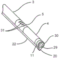
Fig. 1 is a schematic illustration of a surgical ablation probe 1 configured for ablating the function of the posterior nasal nerves. As shown in the figures, the surgical ablation probe 1 and its alternative embodiment is a cryoablation probe. However, alternative ablation and treatment modalities, including radiofrequency, laser, microwave, ultrasound, and chemical ablation, are still within the scope of the present invention. The surgical ablation probe 1 includes a handle assembly 2, a probe shaft 3, and a camera assembly 6. The handle assembly 2 includes a handle housing 19, a cryogen cartridge container 18, a cryogen cartridge 9, a cryogen control trigger 10, a distal segment actuator rod 8 with a finger grip 17, and a camera tube 12. The probe shaft 3 includes a proximal end 15, a distal end 16, a cryoablation element 4, a distal joint section 5, a proximal section 21, and a camera channel 22. The camera assembly 6 includes a camera head 20, a camera axis 11, a camera hub 13, a camera cable 14, and shows a camera field of view 7 in a distal direction. The probe shaft 3 has a diameter of between about 3mm and 5mm and a length of between about 40mm and 100 mm. A cryoablation element 4 is disposed near the distal end 16 of the probe shaft 3 and is associated with the articular segment 5. The distal articular segment 5 is between about 8mm and 20mm in length and includes a distal end 16. The camera head 20 may include a micro CMOS camera and a light source, and is mounted on the distal end of the camera shaft 11. As shown, the camera field of view 7 is in the distal direction. Cameras with integrated light sources are manufactured by Awaiba, which is described in detail on Awaiba. The camera shaft 11 comprises a hollow flexible tube, which may be metal, or a suitable plastic, such as polyimide. The camera shaft 11 houses the camera and light sources within the camera housing 20, which are connected to the wires of the imaging console (not shown) through the camera hub 13 and camera cable 14. The camera assembly 6 and alternative embodiments will be described in further detail below. The probe shaft 3 also includes a camera lumen 22, the camera lumen 22 abutting the camera tube 12. The cryogen cartridge 9 comprises a supply of cryogen, which may be in liquid or gaseous form. The cryogen cartridge is in fluid communication with the cryoablation element 4 through a cryogen control valve associated with the cryogen trigger 10. When the user depresses the cryogen trigger 10, cryogen flows to the cryoablation element 4. When the user releases the cryogen trigger 10, cryogen flow is terminated. Spent cryogen from the cryoablation element is discharged into the room through the interior of the probe shaft 3 and through ports, not shown, in the handle assembly 2.
Fig. 2A is a side view schematic of the surgical probe 1 with the distal joint section 5 in an axial configuration and the camera head 20 retracted. Fig. 2B is a side view schematic of the surgical probe 1 with the distal joint segment 5 in an axial configuration and the camera head 20 extended. The camera assembly 6 includes a camera head 20, a camera shaft 11, a camera hub 13, a camera cable 14, and an electrical connector, not shown, configured for electrical connection to an imaging display, also not shown. The camera shaft 11 is in slidable relationship with the camera tube 12 and the camera lumen 22 of the probe shaft 3. As shown, the camera head 20 is extended by sliding the camera shaft 11 in a distal direction, and retraction of the camera head 20 is achieved by sliding the camera shaft 11 in a proximal direction.
Fig. 3A is a side view schematic illustration of the surgical probe 1 configured for ablating posterior nasal nerve function with the articular segment 5 and cryoablation element 4 in an axial configuration and the camera assembly 6 retracted to its proximal-most position. Fig. 3B is a side view schematic of the surgical probe 1 with the articular segment 5 and the cryoablation element in a lateral configuration and the camera assembly 4 retracted to its proximal-most position. Fig. 3C is a side view schematic of surgical probe 1 with the articular segment 5 in a lateral configuration and the camera assembly 4 extended to its distal-most position. A distal segment actuator rod 8 controls the position of the distal joint segment 5 and the cryoablation element 4. When the distal segment actuator rod 8 is in its forward position as shown in fig. 3A, the distal joint segment 5 and the cryoablation element 4 are in an axial configuration as shown. When the distal segment actuator rod 8 is pulled in a proximal direction, the distal segment 5 and cryoablation element are deflected to a lateral or non-axial position, as shown in fig. 3B and 3C. Although illustratively referred to herein as an actuator rod 8, it should be understood that other mechanisms may be employed to form the distal joint segment as shown herein, including the use of eccentrically anchored pull wires. The combination of the distal articular segment 5 and the associated camera assembly 6 provides the user with a means to endoscopically examine the nasal cavity in both distal axial and distal lateral directions, and the extension of the camera assembly 6 as shown allows the user to endoscopically examine the sinus from the nasal cavity. The probe shaft 3 may be configured to be torsionally rigid so as to provide rotational steering in addition to lateral steering as described. This allows the camera head 20 to aim at a spherical arc and also provides the user with a means to press the cryoablation element against the lateral nasal wall with a twisting force.
Fig. 4 is a side schematic view of a surgical probe configured for ablating posterior nasal nerve function, showing a sinus dilation balloon 26 mounted on a camera shaft 24 near a camera head 20 of a camera/balloon assembly 23. In the embodiment depicted herein, the posterior nasal nerve ablation probe 1 is substantially identical in form and function to that previously described. In the embodiment shown in this figure, sinus dilation functionality is added by adding a dilation balloon to the distal camera shaft. Sinus dilation refers to the dilation of the mouth of the nasal cavity to facilitate sinus drainage. In this embodiment, the camera/balloon assembly 23 includes: a camera head 20 that maintains the form and function as previously described; a camera shaft 24 including a balloon inflation lumen, not shown; and not shown wires connected to the CMOS camera. The camera hub 25 includes a female luer connector in fluid communication with the balloon inflation lumen, the cable 14, and an electrical connector, not shown. The dilatation balloon 26 is substantially similar to the dilatation balloon used in angioplasty. Those skilled in the art of surgical dilation balloon design and manufacture are familiar with the devices for incorporating dilation balloons as shown in the figures; therefore, it is not necessary to describe the dilatation balloon further. As shown, the camera head 20 is extended and the balloon 26 is inflated. During insertion of the probe into the nasal cavity, the camera head 20 and camera shaft 24 are retracted, and the balloon 26 is deflated and located within the camera shaft lumen 28. To inflate the balloon 26, a syringe is connected to the female luer connector 27 and used to inflate the balloon 27. When fully inflated, balloon 27 may be between about 3mm to 10mm in diameter and may have a functional length of between about 10mm and 20 mm. The camera is used to locate the ostium and the camera head 20 is inserted into the ostium and the balloon 26 is placed in a straddling position within the ostium and the balloon 26 is then inflated to expand the ostium. The balloon 26 is then deflated and the camera head 20 is removed from the sinus.
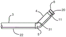
Fig. 5A is a schematic view of the distal end of a surgical probe configured for ablation of posterior nasal nerve function with the distal joint section 5 and cryoablation element 4 in an axial configuration and the camera assembly 6 retracted. Fig. 5B is a schematic view of the distal end of the surgical probe 1 with the distal joint section 5 and cryoablation element 4 in an axial configuration and the camera assembly 6 extended. A camera objective 29 and a camera light source 30 are depicted. Also depicted is a relief slit 31 in the wall of the distal joint segment 5, which is oriented on the lateral deflection side. The relief slits 31 facilitate lateral deflection at relatively short radii by removing shaft material on the inside bend radius. The camera shaft lumen 22 may include a coil reinforcement (not shown) near the distal joint section 5 to prevent kinking.
Fig. 6A is a schematic illustration of the distal end of the surgical probe 1 configured for ablation of posterior nasal nerve function with the distal joint section 5 and cryoablation element 4 laterally configured at approximately 45 degrees and the camera assembly 6 retracted. Fig. 6B is a schematic view of the distal joint section 5 and cryoablation element 4 in an approximately 45 degree lateral configuration with the camera assembly 6 extended. Fig. 6C is a schematic view of the distal end of the surgical probe 1 with the distal joint section 5 and cryoablation element 4 laterally deployed at approximately 90 degrees and the camera assembly 6 retracted. Fig. 6D is a schematic view of the distal end of the surgical probe 1 with the distal joint section 5 and cryoablation element 4 laterally disposed at approximately 90 degrees and the camera assembly 6 extended. Fig. 6E is a schematic view of the distal end of the surgical probe 1 with the distal joint section 5 and cryoablation element 4 laterally deployed at approximately 120 degrees and the camera assembly 6 retracted. Fig. 6F is a schematic view of the distal end of the surgical probe 1 with the distal joint section 5 and cryoablation element 4 laterally disposed at approximately 120 degrees and the camera assembly 6 extended. Fig. 6A-6F illustrate the range of motion of the distal joint section 5, the cryoablation element 4, and the camera assembly 6.
Fig. 7A is a schematic view of the distal end of an alternative embodiment of a surgical probe configured for ablating posterior nasal nerve function with the distal articular segment 5 in an axial configuration and the posterior camera 33 retracted. Fig. 7B is a schematic view of the distal end of an alternative embodiment with the distal joint segment 5 in an axial configuration and the rear view camera assembly 33 in its initial extended stage. Fig. 7C is a schematic view of the distal end of an alternative embodiment with the distal joint segment 5 in the axial configuration and the rear view camera assembly 33 in its fully extended position. Fig. 7D is a schematic illustration of the distal end of an alternative embodiment with the distal joint segment 5 in an approximately 120 degree lateral configuration and the rear view camera assembly 33 in its fully extended position, which is the normal ablation configuration. The rear-view camera assembly 33 provides the user with a means for confirming proper placement of the cryoablation element 4 for the lateral nasal wall proximate the targeted posterior nasal nerve. The rear view camera assembly 33 includes the camera head 20 as previously described, the curved camera axis 32, and the camera hub 13 and camera cable 14 that are not shown but have been previously described. The curved camera axis 32 has a pre-formed curve as shown. Superelastic metal alloys in the form of hypotubes (such as ) To produce a curved camera axis. Those skilled in the art of superelastic metallurgy are familiar with the apparatus used to generate the preformed curve as shown; and therefore need not be further described.
Fig. 8 is a schematic view of the distal end of an alternative embodiment of a surgical probe configured for ablating posterior nasal nerve function, with the distal joint section 5 in an axial configuration and the dual camera assembly 34 including a distal viewing camera and a proximal viewing camera in their extended positions (as illustrated by the camera field of view 7). The dual camera assembly 34 includes a dual camera head 35, a camera shaft 11, a camera hub 13, and a camera cable 14 not shown but described previously. The camera head 35 includes the forward-looking CMOS camera and light source, and a second rear-looking CMOS camera and light source as previously described.
Fig. 9 is a schematic view of the distal end of an alternative embodiment of a surgical probe configured for ablation of posterior nasal nerve function, including a cryoablation element 39 configured with a lateral injection needle 37, a lateral fenestration 36, and a local anesthetic delivery surface 38. As depicted, the distal joint segment 5 is in an approximately 120 degree lateral configuration, the dual camera assembly 34 camera is in its fully extended position and the lateral injection needle 37 is deployed for injecting anesthetic into the posterior nasal nerve ablation target area of the lateral nasal wall. The local anesthetic delivery surface 38 is configured for applying a local anesthetic to the lateral nasal wall proximate the targeted posterior nasal nerve to anesthetize the area prior to injection of the anesthetic through the lateral needle 37. The lateral needle 37 is a hypotube, which may be made of a super-elastic metal, such as The lateral needle 37 is in fluid communication with a proximal syringe (not shown) and is configured with a proximal needle deployment mechanism (not shown). Those skilled in the art of surgical needle probes are familiar with the devices for forming deployable needles as described above; and therefore need no further explanation. The local
 anesthetic delivery surface 38 may include an anesthetic carrying device, such as a hydrophilic coating, or a foam or fibrous absorbable material, that can absorb the local anesthetic and deliver the anesthetic to the nasal wall surface by contact. The local anesthetic delivery surface 38 can include an abrasive material configured to abrade the nasal wall to enhance the effectiveness of the local anesthetic. The abrasive material may include crystalline lidocaine or similar anesthetic material.
Fig. 10 is a schematic view of the distal end of an alternative embodiment of a surgical probe configured for ablating posterior nasal nerve function, including a distal camera 44 and working channel 41 mounted at the distal end of cryoablation element 4, configured to introduce surgical instruments into the nasal cavity under image guidance. As shown, the balloon catheter 40 is inserted into the working channel 41 with the distal ends of the balloon 42 and catheter shaft 43 extending beyond the distal end of the working channel 41. The proximal end of the catheter shaft is depicted as entering the working channel 41 through the working channel tube 47. The far side camera 44 is connected to an image display, not shown, by a cable 45 and an electrical connector 46. As shown, the distal joint segment 5 is in a 90 degree lateral configuration. The range of motion of the distal joint segment 5 is substantially the same as previously described and is between about 0 degrees and 120 degrees. Working channel 41 may be configured for use with catheters and probes of between about 3Fr and 6 Fr.
As noted above, many treatment modalities are within the scope of the present invention. Additional treatment modalities, including cryoablation elements, are described in U.S. patent application publication No. 2015/0164571, entitled "Apparatus and Methods for Treating Rhinitis," which is incorporated herein by reference in its entirety. Fig. 11A-11D illustrate views of one such alternative embodiment of a cryoablation element in accordance with embodiments of the present invention. In particular, the side view of fig. 11A shows structure or member 83 formed as an annular elongated structure having arcuate edges for presenting an atraumatic surface. Rather than being formed as a spring-like structure, the structure 83 may be formed from a relatively rigid wire or member, the structure 83 maintaining its configuration when pressed against a tissue surface. The structure 83 may form a continuous structure defining an opening therethrough, such as a ring or elongated ring-like member, through which the opening passes. The structure 83 may be completely contained within the expandable structure 81, and the expandable structure 81 may be formed to have a predetermined shape that is expandable or non-expandable when inflated by a cryogen. Further, expandable structure 81 may be formed to completely surround structure 83 without being supported by or attached to structure 83 itself. Such a structure 83 may provide a configuration that presents a low profile as the device is advanced through the nasal cavity and between the turbinate tissues. However, due to the relatively flat shape and rigidity and integrity of the structure 83, the structure 83 may be used to manipulate, move or otherwise separate the tissues of the nasal cavity without having to rely on the expandable structure 81. In addition, the low profile enables the structure 83 to be ideally positioned within a narrow range, such as the fornix (cul-de-sac) near the posterior nasal nerve (as shown by fornix 13 shown in FIG. 1 of previously incorporated U.S. patent application publication No. 2015/0164571). When the expandable structure 81 is in its contracted state, it may form a flattened shape, and when expanded, the expandable structure 81 may expand to maintain a configuration that is not supported by or attached to the structure 83. Because structure 83 may be formed from a member that is solid along its length, cryogen may be introduced directly into expandable structure 8I through a distal opening defined in probe shaft 145.
Alternatively, the structure 83 may be formed from a hollow tubular member that is itself formed into a continuous or annular shape. In such embodiments, the cryogen may optionally be introduced through the hollow tubular member and dispersed inside the expandable structure 81 through one or more openings that may be defined along the tubular member. In yet another alternative, the structure 83 may be formed in a flat shape rather than a ring shape. In this configuration, the structure may be solid or hollow such that the cryogen may be introduced through the structure and into the interior of the expandable structure 81 via one or more openings defined along the structure.
The structure 83 may extend and remain attached to the probe shaft 145, but the remainder of the structure 83 extending within the expandable structure 81 may remain unattached or unconnected to any portion of the expandable structure 81. Thus, once expandable structure 81 is inflated with a cryogen, structure 83 can be adjusted in position or moved by manipulating probe shaft 145 relative to the interior of expandable structure 81 to enable targeted positioning and cooling of the tissue region upon contact with the outer surface of expandable structure 81. For example, structure 83 may be pressed laterally on specific areas of underlying tissue to stretch or thin the contacted tissue areas to facilitate the freezing process. When the structure 83 is adjusted in position relative to the expandable structure 81, the expandable structure 81 can remain in a resting position against the contacted tissue area, allowing limited repositioning of the structure 83 within its interior.
Alternatively, in other variations, the structure 83 may be attached along an interior portion of the expandable structure 81 at a particular portion of the structure 83 or along the entire structure 83. For example, the structure 83 may be attached, adhered, or otherwise coupled to the expandable structure 81 in its entirety, while in other variations a distal portion of the structure 83 may be attached, adhered, or otherwise coupled to a distal portion of the expandable structure 81, while in still other variations portions of the structure 83 may be attached, adhered, or otherwise coupled to the expandable structure 81 along its sides. Any of these variations may optionally be used depending on the desired interaction and treatment between the structure 83, expandable structure 81 and the underlying tissue region to be treated.
In yet another alternative variation, a lumen 84 for introducing coolant into the interior of the expandable structure 81 may extend through the distal end of the probe shaft such that coolant is released internally at a more distal location. As shown, cryogen lumen 84 may be supported along structure 83, for example, via a rod or member 85 extending across structure 83. This particular variation may allow a cryogen to be introduced into the distal portion of the interior of the expandable member 81. This variation or a variation in releasing cryogen from the opening of the probe shaft may be utilized as desired.
Fig. 11B shows a side view of the embodiment of fig. 11A, illustrating how the structure 83 can be formed from a relatively flat configuration relative to the expanded expandable structure 81. Due to the structural integrity of structure 83 and its relatively flat profile, structure 83 may provide targeted treatment of tissue as it is contacted by the device. Fig. 11C shows a side view when the expanded expandable structure 81 is pressed in a longitudinal direction by its distal tip against the underlying tissue surface S. The relative strength of the structure 83 provides the ability to press the device against the tissue surface so that the remainder of the expandable structure 81 can retain its expanded configuration to potentially isolate other surrounding tissue regions. Fig. 11D also shows the device when the structure 83 is pressing the tissue surface S laterally along its sides so that the structure 83 lies flat. The contacted tissue region may be treated while the rest of the surrounding tissue is potentially isolated by the expanded structure 81.
While the treatment end effector (effector) is designed for application along the tissue region defined by the fornices, the same end effector may be used in other regions of the nasal cavity. For example, once ablation is performed along the fornix, the end effector may be moved to an adjacent tissue region, such as the region immediately adjacent the fornix, and ablation treatment may be effected again. Additionally and/or alternatively, the end effector may also be used to further treat additional tissue regions, for example, the posterior of the superior turbinate, the middle turbinate, and/or the inferior turbinate (any one, two, or all three of the regions). In either case, once the fornix has been ablated, the end effector may remain in place until the tissue region has been partially or fully thawed before the end effector is moved to the adjacent tissue region for further treatment.
Once treatment is complete, or during treatment, the tissue region may be evaluated using any number of mechanisms. For example, the tissue region may be visually assessed during and/or after ablation using an imager.
As described herein, the device may be used with temperature sensors, such as thermistors, thermocouples, and the like, which may be mounted along the shaft, within or along the expandable structure 81, along the structure 83, and the like, not only for monitoring the temperature of the cryogen, but also the temperature of the tissue region and the temperature during treatment.
Additionally and/or alternatively, the expandable structure 81 may be vibrated while the structure 83 is held against the interior and tissue regions of the expandable structure 81 using any number of vibration actuators, which may be suitably mounted at any location along the device. The vibration may be applied directly to the tissue area or, for example, through a gel layer that facilitates vibratory contact with the tissue.
Additionally and/or alternatively, other biocompatible agents may be used in combination with the freezing process. For example, in one variation, an anesthetic may be applied to the tissue region to be treated prior to or during the freezing process. This and other alternative features described may utilize not only the variations shown and described in fig. 11A and 11B, but any other embodiment described in U.S. patent application publication No. 2015/0164571, previously incorporated and described herein.
Fig. 12A is a perspective view of an integrated therapy and imaging device 1200 with a display 1208, and fig. 12B is a perspective view of the distal end of the integrated therapy and imaging device of fig. 12A, in accordance with an embodiment of the present invention. The device 1200 may operate similarly to the probe 1 described above, except that it may include a display 1208 for viewing during insertion of the distal end of the device 1200 into the nasal cavity of a patient.
Referring to fig. 12A, it can be seen that the handle 1202 includes an actuator 1220 that can cause a cryogen contained in a cryogen vessel (not shown) housed in the handle 1202 to flow through the cannula 1216 to the cryoablation element 1218. As can be seen in fig. 12B, the cryoablation element 1218 can be an expandable structure having an internal structure 1222, which can be similar to the expandable structure 81 and structure 83 described above with reference to fig. 11A-11D. A sleeve 1216 extends from an opening in housing 1210 of apparatus 1200.
For use in the nasal cavity, it may be preferred that the imaging assembly 1214 have a field of view of at least 75 degrees and a line of sight of at least 5 mm. Further, it may be preferred that the imaging assembly 1214 have an effective diameter of less than 2.5 mm.
Fig. 12C shows an embodiment of the apparatus 1200 with a malleable imaging cannula 1212C. The sleeve 1212C may be constructed of a ductile material such as aluminum, copper, annealed steel, or some polymer. The sleeve 1212C may be shaped in situ to facilitate a desired field of view of the ablation element 1218. The initial shape is shown as 1275A and the exemplary final shape is shown as 1275B. Once the cannula 1212C has assumed the desired shape, a flexible or elastomeric imaging member may be inserted into the cannula 1212C and then pushed forward until it exits the distal end of the cannula and is naturally in the proper position as defined by the cannula 1212C a priori (apriori). Fig. 12D shows the imaging assembly 1204D inserted through the malleable imaging cannula 1212C after the cannula 1212C has been formed into the shape 1275B described above. The imaging assembly 1204D may be constructed of an elastic material, such as a coil or nitinol, or an elastomer, such as silicone or polyurethane. The elastic nature of this variation of the assembly 1404D allows it to be easily inserted into the cannula 1212C described with reference to fig. 12C and pushed out of the distal end of the malleable cannula 1212C.
FIG. 12E illustrates another embodiment of a device 1200 having a shape memory image component 1204E. Shape memory image component 1204E is made of a material having shape memory, such as spring steel, nitinol, shape memory polymer, or other suitable shape memory material. The shape memory image component 1204E can have an original shape that allows for a desired viewing angle and/or position relative to the treatment element 1218. The shape memory image component 1204E may be inserted into the cannula 1212E and be sufficiently resilient to assume a linear shape when moved through the cannula 1212E and its original shape when it exits the cannula 1212E. The original shape may be any suitable shape and may have a curved, saw tooth or bent shape as desired.
Fig. 13A and 13B show simplified schematic diagrams of alternative arrangements of an imaging sensor 1302 and a light element 1304 according to embodiments of the invention. It should be understood that these arrangements of imaging sensors 1302 and 1304 may be used in imaging assembly 1214 or any other imaging assembly described herein. Fig. 13A shows a coaxial arrangement of an imaging sensor 1302A and a light element 1304A. For example, the light element 1304A can be a ring of LEDs surrounding the imaging sensor 1302A. FIG. 13B shows an off-axis arrangement, where the optical element 1304B directs light off-axis from the imaging sensor 1302B.
The device 1200 may include an articulation actuator embedded in or attached to the device handle 1202 that may articulate either or both of the imaging assembly 1214 and/or the cryoablation element 1218 in the manners described herein. For example, the actuator may be configured to articulate the cannula 1216 or the articulation region of the imaging lumen 1212 as described herein with respect to fig. 1-9 and 14A-21C.
As described above, the device 1200 may include a display 1208 operatively coupled to the imaging assembly 1214. Display 1208 may be a smart phone, tablet device, or other stand-alone display that can output video having a desired resolution. Display 1208 may be integrated with device 1200 or, alternatively, may be removably coupled from device 1200. For example, display 1208 may be removably coupled to display adapter 1206 by any suitable connection that allows for attachment and detachment as desired by a user. For example, display adapter 1206 may include one or more magnetic elements that attract complementary magnetic elements on display 1208 to hold display 1208 in place as shown, but allow a user to detach display 1208 as desired. Display adapter 1206 may also include the necessary electrical connections to connect display 1208 to imaging assembly 1204 and any components thereof. Thus, when connected to the display adapter 1206, the display 1208 can receive signals from the imaging assembly 1204 and its components to display the cryoablation element 1218 and surrounding area during use of the device 1200. Placing display 1208 on device 1200 as shown may be advantageous over using an external display at a remote location because display 1208 may more easily fall in the line of sight of a healthcare provider during use of device 1200. As such, the healthcare provider will not need to look away from the patient when using the device 1200.
Fig. 14A-14E show views of the distal end of an integrated therapeutic and imaging device 1400 according to an embodiment of the invention. As described above, the device 1400 may be used to provide therapy in the nasal cavity. For example, the device 1400 may be used to deliver energy to tissue in the nasal cavity to ablate the posterior nasal nerves to treat rhinitis. As can be seen in fig. 14A, the device 1400 may have a treatment element 1410 for delivering energy to tissue via the working cannula 1408. For example, the treatment element 1410 may be a cryoablation element as previously described.
To provide visualization of the treatment element 1410 during positioning and treatment, an imaging accessory 1401 may be provided. Imaging accessory 1401 may include an imaging cannula 1402 with an imaging assembly 1404 disposed at a distal end of imaging cannula 1402. Imaging cannula 1402 and imaging assembly 1404 may be generally similar to imaging cannula 1212 and imaging assembly 1214 described above with respect to fig. 12A-12B, except that instead of extending from within a housing in device 1400, they are coupled externally to working cannula 1408 via one or more couplers 1406. Coupler 1406 may be a C-clip that keeps imaging accessory 1401 coupled to working cannula 1408, but allows for specific movement of imaging accessory 1401 and imaging assembly 1404 relative to treatment element 1410. For example, coupler 1406 may be a friction fitting that allows relative movement between working cannula 1408 and imaging cannula 1402, but only when the relative friction is above a certain threshold. For example, the threshold relative friction may be 1/2 to 1 pound of force. This would allow imaging cannula 1402 to remain coupled to working cannula 1408 during normal operation of device 1400, but still allow relative translation with minimal required force applied by the user. The coupler 1406 may be made of polyurethane, latex, silicone, or other similar material.
Although not shown in fig. 14A, the device 1400 may have a display disposed at the proximal end of the device that is operatively coupled to the imaging assembly 1404 for visualization of the treatment element 1410. Alternatively, device 1400 may have a proximally disposed display adapter that is operatively coupled to imaging assembly 1404 via wiring or optical fibers disposed in imaging cannula 1402. The display adapter may be configured to connect to any suitable external display for providing visualization of the image detected by imaging assembly 1404.
To view the treatment element 1410 from an optimal perspective or position, the imaging attachment 1401 can include an articulation region 1403 operably coupled to the imaging assembly 1404 and configured to articulate the imaging assembly 1404. As shown in fig. 14B, imaging assembly 1404 may be configured to translate axially in the X-direction in order to adjust the distance from treatment element 1410. The axial translation in this direction may be in the range of about 5mm to about 60 mm. The imaging assembly 1404 may also be configured to translate vertically in the Y-direction in order to adjust the height of the imaging assembly 1404 relative to the working cannula 1408. The vertical translation in this direction may be in the range of about 1mm to about 10 mm. The imaging assembly 1404 may also be configured to translate laterally in order to adjust the angle α relative to a central axis 1412 of the imaging assembly. This may allow the imaging assembly to obtain a desired viewing angle for the treatment element 1410. The lateral translation may be in a range of about 0 degrees to about 30 degrees. Additionally, the imaging assembly 1404 may be configured to rotationally translate in the "R" direction about an insertion axis 1414 of the working cannula 1408. The range of rotation may be a full 360 degrees about the insertion axis 1414, 0 to 180 degrees about the insertion axis 1414, or 45 degrees about the insertion axis 1414 in either direction (from the initial position shown in fig. 14A). This may allow imaging assembly 1404 to view treatment element 1410 from different vantage points that may be required during use of device 1400. These degrees of freedom will also allow imaging assembly 1404 to be positioned at a different location during insertion than during delivery of a therapeutic agent by treatment element 1410.
Because treatment elements, such as cryoablation elements (or other ablation elements), can produce extreme temperatures, the imaging assembly can be coupled to a temperature control element 1425 (shown schematically in fig. 14A). The temperature control element 1425 may include: a temperature sensor for detecting the temperature of the imaging assembly 1404; and a heating or cooling element controllable in response to the detected temperature for maintaining the imaging assembly within an operating temperature range during activation of the therapy element 1410. For example, if the device 1400 uses a cryoablation element, a heating element such as a heating coil may be provided to maintain the imaging assembly within a suitable operating temperature. In some embodiments, the optical elements of imaging assembly 1404 may be used as heating elements to maintain the imaging assembly within a suitable operating temperature. For example, one or more LEDs used as illumination elements may also be used as heating elements to maintain imaging assembly 1404 (including the image sensor) within a suitable operating temperature.
Referring back to fig. 14A, it can be seen that the imaging assembly 1404 may be in a default position prior to any articulation. In fig. 14B, imaging assembly 1404 may be in a raised position after its vertical translation. In fig. 14C, imaging assembly 1404 may be raised vertically and tilted laterally to point treatment element 1410 from above. Also, in FIG. 14D, imaging assembly 1404 is rotationally translated from the position in FIG. 14B. Although not shown in detail in fig. 14A-14D, in some embodiments, articulation of the imaging assembly 1404 may be achieved using pull wires, slides, and/or dials terminating at the proximal end of the device, where a user may manipulate the imaging assembly 1404 with their hands. For example, pull wires coupled to imaging assembly 1404 may extend through imaging cannula 1402 and may be tightened or loosened by a user using a rod or other joint actuator in order to cause joint region 1403 to translate imaging assembly 1404 axially, vertically, laterally, and rotationally as desired. In some embodiments, the axial translation and the rotational translation may be directly caused manually by a user, while the lateral translation and the vertical translation may be actuated by a rod coupled to the guide wire.
As shown in fig. 14A-14D, the imaging assembly 1404 may be disposed proximal to the treatment element 1410 in order to minimize engagement with nasal tissue when the distal end of the device 1400 is inserted into the nasal cavity. In particular, imaging assembly 1404 may be sized to fit within the dimensions of treatment element 1410, such that treatment element 1410 effectively protects the imaging assembly from engagement with nasal tissue. Since treatment element 1410 has a predominantly vertical profile, it may be desirable to stack imaging assembly 1404 and its components vertically within that profile. Additionally, in some embodiments, it may be desirable to limit the articulation of imaging assembly 1404 so as to remain within the contours of treatment element 1410.
FIG. 14E illustrates a schematic view of one or more irrigation and/or evacuation ports 1430 provided on the imaging assembly 1404 and/or working cannula 1408, in accordance with embodiments of the invention. As can be seen in fig. 14E, a port 1430 for irrigation and/or evacuation may be embedded on the working cannula 1408 or on the body of the imaging assembly 1404. Port 1430 may be fluidly coupled to a channel within working cannula 1408 and/or imaging cannula 1402 to allow fluid to pass through, exit at the distal end of working cannula 1408, and/or be aspirated back out of the body. Although only schematically shown in fig. 14E, the irrigation port 1430 may be designed to direct fluid at the imaging assembly 1404 and the evacuation port may be positioned about 180 degrees around the imaging assembly from the irrigation port 1430 in order to capture fluid flowing to the imaging assembly 1404. The irrigation port lumen diameter can be in the range of about 0.005 inches to 0.025 inches. The evacuation port lumen diameter can be in the range of 0.005 inches to 0.025 inches and can be shaped to the outer edge of the imaging element.
14A-14E, it should be understood that multiple couplers 1406 may be used so that there are multiple attachment points between the imaging accessory 1401 and the working cannula 1408. In some embodiments, the coupler 1406 may provide attachment points on the joint region 1403, allowing the therapy element 1410 to articulate with the imaging assembly 1404 or independently of the imaging assembly 1404.
One can appreciate the benefits of integrating imaging accessories, such as imaging accessory 1401, with the features previously described. First, the integration of the imaging accessory with the treatment element may allow a user, such as a healthcare provider, to perform a treatment procedure with visualization using a single hand. This may reduce the time, cost, and labor involved in a given procedure, and may reduce the difficulty of a given procedure. Second, the integration of the imaging attachment with the treatment procedure will improve the visibility of such procedures, as it will ensure that the imaging will be able to reach sufficiently posteriorly to obtain a detailed visualization of the target region. This is in contrast to rigid or flexible endoscopes, which generally do not allow sufficient access for imaging of the associated working tool. Since the imaging accessory is coupled to the working device and can be maneuvered to and then fixed in a desired position relative to the treatment element, it will certainly reach behind enough to provide a sufficiently detailed imaging of the treatment element and the target region.
Figure 15 illustrates a perspective view of an articulating imaging attachment 1500 in accordance with an embodiment of the invention. The joint imaging accessory 1500 may include a handle attachment base 1516 that may connect the imaging accessory 1500 to a handle of a treatment device, as will be described with reference to fig. 16A-16B, 17A-17B, and 18A-18B. The joint imaging accessory 1500 may have an imaging cannula 1502 similar to the imaging cannula 1402 described above, with an imaging assembly 1504 (similar to the imaging assembly 1404 described above) disposed at the distal end. Imaging cannula 1402 may be coupled to a working cannula of a device via one or more couplers 1506 similar to coupler 1406 described above. The joint imaging accessory 1500 may also have a joint region 1503 similar to the joint region 1403.
To actuate articulation of the imaging assembly 1504, the articulating imaging accessory 1500 may have a curved rod 1518 that translates back and forth as indicated by arrow 1517. The curved rod 1518 can be coupled to a pull wire housed in the imaging cannula 1502 and coupled to the imaging assembly 1504 such that when the curved rod is initially pulled in a proximal direction, the pull wire attached to the imaging assembly 1504 tightens and causes the imaging assembly 1504 to translate vertically. When the curved rod 1518 reaches the last portion of the stroke (e.g., the last 2mm-3mm), the imaging assembly 1504 may stop translating vertically and may begin translating laterally to angle the imaging assembly 1504 relative to its central axis. The angle may be in the range of about 0 degrees to about 20 degrees from the central axis of imaging assembly 1504 without losing vertical translation, similar to the lateral translation angle a described above with respect to imaging assembly 1404. Thus, it can be seen that the curved rod 1518 can allow for vertical and lateral translation of the imaging assembly 1504. To lock the imaging assembly 1504 at a desired viewing angle or position, a locking mechanism 1520 (shown schematically in fig. 15) may be provided. Locking mechanism 1520 may be any suitable mechanism that holds curved stem 1518 in a desired position. For example, when a user translates the curved rod 1518 to a desired position, the locking mechanism 1520 can automatically or when a button or other mechanism is actuated hold the curved rod 1518 in the desired position such that the position and/or perspective of the imaging assembly 1504 is fixed relative to the treatment element of the device to which the imaging accessory 1500 is attached.
The vertical translation and the lateral translation of the imaging assembly 1504 will now be described with reference to fig. 16A-16B, 17A-17B, and 18A-18B. Figures 16A and 16B illustrate views of a device 1600 having an integrated articulating imaging accessory 1500 in an unarticulated position according to embodiments of the present invention. As can be seen in fig. 16A, when imaging assembly 1504 is not articulated, curved rod 1518 is in its distal-most position. As the curved rod 1518 is pulled proximally (or in the direction 1700 shown in fig. 17A), the imaging assembly 1504 may begin to articulate vertically.
Figures 17A and 17B illustrate a view of a device 1600 having an articulating imaging accessory 1500 in a raised position, in accordance with an embodiment of the present invention. As can be seen in fig. 17A-17B, bending rod 1518 translates proximally in direction 1700 relative to the position of bending rod 1518 in fig. 16A-16B, and this translation bends articulation region 1503, which causes vertically translating imaging component 1504 to be located at an elevation above working cannula 1608.
As described above, further translation of the curved rod 1518 in the direction 1700 may cause lateral articulation of the imaging assembly 1504 at an angle relative to the central axis of the imaging assembly 1504 without losing the previously obtained vertical translation. Figures 18A and 18B illustrate views of a device 1600 having an articulating imaging accessory 1500 in a raised and downwardly tilted position, in accordance with embodiments of the present invention. As can be seen in fig. 17A-17B, curved rod 1518 translates in direction 1700 to a proximal-most position relative to the position of curved rod 1518 in fig. 17A-17B, and this translation causes joint region 1503 to further bend, which causes imaging assembly 1504 to tilt downward toward treatment element 1610.
Fig. 19 illustrates a perspective view of an imaging accessory 1900 having a malleable distal portion 1903, in accordance with an embodiment of the invention. The imaging accessory 1900 may be similar to the imaging accessory 1500 except that instead of a lever actuated articulation region, the imaging accessory has a malleable distal portion 1903, an imaging component 1904 disposed on the distal portion 1903, and a proximal rigid portion 1905 coupled to a handle attachment base 1916. Rather than actuating articulation to adjust the position and/or viewing angle of the imaging assembly 1904 as in the embodiments described above, the malleability of the distal portion 1903 may allow the portion to be shaped (such as shape 1903A) by a user for a desired position and/or viewing angle of the imaging assembly 1904. In some embodiments, the proximal rigid portion 1905 may be made of rigid steel, brass, aluminum, copper tubing, or rigid plastic, and the malleable distal portion 1903 may be made of the same material as the rigid portion 1905, but may be fully annealed, selectively annealed, thinned, or otherwise processed so as to have sufficient malleability to be shaped by a user prior to use. Alternatively, the malleable distal portion 1903 may be made of a composite material of a polymer and a metal. The malleable distal portion 1903 may be malleable enough to be manually shaped by a user, with or without the application of additional energy, such as heat. Once formed as desired, the malleable distal portion 1903 may remain semi-flexible, but typically retains its shape during operation.
Because a particular shape with the malleable distal portion 1903 may be desired for a given procedure, a template may be used to shape the malleable distal portion 1903. The template may allow for consistency among multiple healthcare providers or other users while still allowing the user to provide a choice of the exact shape of the malleable distal portion 1903 in order to adjust the perspective and position of the imaging assembly 1904 relative to the treatment element. Fig. 20A and 20B illustrate an exemplary template 2000 for shaping an extendable distal portion 1903 of an imaging accessory 1900 in accordance with an embodiment of the present invention. The template 2000 may have one or more forming channels 2003 in which malleable distal portions 1903 may be placed for forming. The shaping channel 2003 can be designed to achieve a desired default shape of the malleable portion 1903, which can provide an optimal position and/or angle for the treatment element of the device. The user may then press the distal portion to follow the contour of the shaped channel 2003 to obtain the desired shape for the given procedure. It should be understood that different templates may be generated and used for different procedures and/or different patients. For example, a given procedure may require different shapes to achieve the optimal position or angle, and thus the malleable portion 1903 may be shaped using different stencils or different shaping channels within the same stencil (as shown in fig. 20A and 20B). A single template, such as template 2000, may have multiple shaped channels to account for anatomical variations while still providing a uniform shape between healthcare providers.
FIG. 21A shows a perspective view of a device 2100 with an imaging accessory 1900 according to an embodiment of the invention. The device 2100 may be a treatment device having a working cannula 2108 and a distally disposed treatment element 2110, similar to the devices described above. As with the imaging accessory 1500, the handle attachment base 1916 of the imaging accessory 1900 may snap onto the handle of the device 2100, and the connection between the handle attachment base 1916 and the device 2100 may allow the base 1916 to translate axially in the X-direction (shown in fig. 21A) and rotationally in the R-direction (shown in fig. 21A) around the distal nose of the handle of the device 2100. The rigidity of the portion 1905 will ensure one-to-one rotation between the handle attachment base 1916 and the imaging assembly 1904. As such, the axial translation and rotational translation may be manually accomplished by a user by axially translating and rotationally attaching the base 1916. The ranges of axial translation and rotational translation may be the same as described above with respect to imaging assembly 1404 and imaging assembly 1504. The imaging accessory may also be coupled to shroud 2108 using a coupler 1906 similar to the couplers described above. Fig. 21B and 21C show perspective views of a device 2100 with an imaging accessory 1900 in various rotational positions relative to fig. 21A, in accordance with an embodiment of the present invention. As can be seen in fig. 21A-21C, the imaging assembly 1904 remains in the same position and view as the original shape, and is only rotated in the R direction to various positions about the insertion axis of the shroud 2108.
The applications of the disclosed invention discussed above are not limited to certain treatments or areas of the body, but may include any number of other treatments and body areas. Modifications of the above-described methods and apparatus for practicing the invention, as well as variations of aspects of the invention that are apparent to those of skill in the art, are intended to be within the scope of the present disclosure. Moreover, various combinations of aspects between examples are also contemplated and are considered to be within the scope of the present disclosure.
Other variations are within the spirit of the invention. Thus, while the invention is susceptible to various modifications and alternative constructions, certain illustrated embodiments thereof are shown in the drawings and have been described above in detail. It should be understood, however, that there is no intention to limit the invention to the specific form or forms disclosed, but on the contrary, the intention is to cover all modifications, alternative constructions, and equivalents falling within the spirit and scope of the invention, as defined by the appended claims.
The use of the terms "a" and "an" and "the" and similar referents in the context of describing the invention (especially in the context of the following claims) is to be construed to cover both the singular and the plural, unless otherwise indicated herein or clearly contradicted by context. The terms "comprising," "having," "consisting of …," and "containing" are to be construed as open-ended terms (i.e., meaning "including, but not limited to,") unless otherwise noted. The term "connected" should be interpreted as partially or fully inclusive, attached, or joined together, even if certain intermediaries are present. Recitation of ranges of values herein are merely intended to serve as a shorthand method of referring individually to each separate value falling within the range, unless otherwise indicated herein, and each separate value is incorporated into the specification as if it were individually recited herein. All methods described herein can be performed in any suitable order unless otherwise indicated herein or otherwise clearly contradicted by context. The use of any and all examples, or exemplary language (e.g., "such as") provided herein, is intended merely to better illuminate embodiments of the invention and does not pose a limitation on the scope of the invention unless otherwise claimed. No language in the specification should be construed as indicating any non-limiting element essential to the practice of the invention.
Preferred embodiments of this invention are described herein, including the best mode known to the inventors for carrying out the invention. Variations of those preferred embodiments may become apparent to those of ordinary skill in the art upon reading the foregoing description. The inventors expect skilled artisans to employ such variations as appropriate, and the inventors intend for the invention to be practiced otherwise than as specifically described herein. Accordingly, this invention includes all modifications and equivalents of the subject matter recited in the claims appended hereto as permitted by applicable law. Moreover, any combination of the above-described elements in all possible variations thereof is encompassed by the invention unless otherwise indicated herein or otherwise clearly contradicted by context.
All references, including publications, patent applications, and patents, cited herein are hereby incorporated by reference to the same extent as if each reference were individually and specifically indicated to be incorporated by reference and were set forth in its entirety herein.
Claims (32)
1. A single-handed, hand-held, integrated therapy and imaging device, the device comprising:
a hollow elongate cannula having a proximal portion and a distal portion defining an axis extending therebetween;
a treatment element coupled to the distal portion of the hollow elongate cannula, the treatment element comprising a ring-like structure having a low-profile shape with profile dimensions comprising: (i) an axial dimension along an axis of the hollow elongate cannula; (ii) a vertical dimension perpendicular to the axial dimension; and (iii) a transverse dimension perpendicular to the axial dimension and a vertical dimension, the vertical dimension being greater than the transverse dimension;
an imaging assembly coupled to the cannula and configured to provide visualization of the treatment element in the nasal cavity; and
a joint region operably coupled to the imaging assembly and configured to articulate the imaging assembly in degrees of freedom relative to an insertion axis of the hollow elongate cannula into the nasal cavity; and is
Wherein the imaging assembly is disposed proximal to the treatment element and is sized to fit within the contour dimensions of the treatment element such that the treatment element protects the imaging assembly from nasal tissue during insertion of the device into the nasal cavity.
2. The apparatus of claim 1, wherein the degree of freedom is selected from the group consisting of:
a vertical translation for adjusting a height of the imaging assembly relative to an insertion axis of the hollow elongate cannula;
axial translation for adjusting an axial position of the imaging assembly along the insertion axis of the hollow elongate cannula;
a lateral translation for adjusting an angular position of the imaging assembly relative to a central axis of the imaging assembly; and
rotational translation of the imaging assembly about the insertion axis of the hollow elongate cannula.
3. The device of claim 2, wherein the articulation region is configured to adjust the height of the imaging assembly relative to the insertion axis in a range of about 1mm to about 10 mm.
4. The apparatus of claim 2, wherein the articulation region is configured to adjust the axial position in a range of about 5mm to about 60 mm.
5. The device of claim 2, wherein the articulation region is configured to adjust the angular position of the imaging assembly relative to the central axis of the imaging assembly in a range of about 0 degrees to about 30 degrees.
6. The device of claim 2, wherein the articulation region is configured to adjust the angular position of the imaging assembly relative to the central axis of the imaging assembly in a range of about 0 degrees to about 20 degrees while maintaining a height of the imaging assembly relative to the hollow elongate cannula.
7. The apparatus of claim 2, wherein the articulation region is configured to translate the imaging assembly rotationally in a range of about 0 degrees to about 360 degrees about the insertion axis of the hollow elongate cannula.
8. The device of claim 2, wherein the imaging assembly is coupled to the hollow elongate cannula such that the articulation region is configured to articulate the imaging assembly independently of the therapy element.
9. The apparatus of claim 2, wherein the imaging assembly includes a detector and a light element, and wherein the imaging assembly is coupled to an outer surface of the hollow elongate cannula via a coupler attachment.
10. The apparatus of claim 2, wherein the imaging assembly including a detector and an optical element is partially located within the lumen of the cannula.
11. The apparatus of claim 2, wherein the imaging assembly comprises a coaxially arranged detector and light element.
12. The apparatus of claim 2, wherein the imaging assembly includes a detector and a light element that are off-axis with respect to each other.
13. The device of claim 2, wherein the imaging assembly is coupled to the cannula such that the articulation region is configured to articulate the imaging assembly simultaneously with the treatment element.
14. The device of claim 2, further comprising a locking mechanism configured to maintain a fixed position of the imaging assembly relative to the treatment element when the imaging assembly is articulated to a desired viewing angle or position for the treatment element.
15. The apparatus of claim 14, wherein the imaging assembly is vertically stacked relative to the hollow elongate cannula so as to minimize engagement with the nasal tissue.
16. The device of claim 2, further comprising an image display disposed at a proximal end of the device and operably coupled to the imaging assembly for visualization of the therapeutic element on the image display.
17. The device of claim 2, further comprising a display adapter disposed at a proximal end of the device and operatively coupled to the imaging assembly.
18. The device of claim 17, further comprising a display removably coupled to the display adapter for visualization of the treatment element on the display.
19. A device as described in claim 18, wherein the display adapter comprises a magnetic adapter for removably coupling the display to the proximal end of the device.
20. The device of any one of claims 1-19, wherein the treatment element comprises at least one of a cryoablation element, a radio frequency ablation element, an ultrasound ablation element, a laser ablation element, a microwave ablation element, and a chemical ablation element.
21. The device of claim 20, further comprising a temperature control element coupled to the imaging assembly, the temperature control element configured to maintain the imaging assembly within an operating temperature range during activation of the therapy element.
22. The device of claim 2, wherein the treatment element comprises a cryoablation element expandable from a collapsed configuration to an expanded configuration; and is
Wherein the cryoablation element is configured to apply therapy to at least one posterior nasal nerve of a tissue region of a lateral nasal wall of the nasal cavity to treat rhinitis.
23. The device of claim 2, further comprising a handle coupled to the proximal portion of the hollow elongate cannula, the handle comprising a joint actuator configured to actuate the joint region.
24. The apparatus of claim 2, further comprising a handle coupled to the proximal portion of the hollow elongate cannula,
wherein the imaging assembly is disposed on a flexible distal portion of an imaging cannula that includes a rigid proximal portion coupled to a handle of the device.
25. The device of claim 24, wherein the rigid proximal portion is removably coupled to the handle of the device by a handle attachment base configured for axial translation along a nose of the handle and rotational translation about a central axis of the nose of the handle.
26. The device of claim 24, wherein the flexible distal portion is formable prior to insertion into the nasal cavity to obtain a desired perspective or position of the imaging assembly relative to the treatment element.
27. The apparatus of claim 2, wherein the treatment element comprises a predominantly vertical profile dimension, and
wherein the imaging assemblies are vertically stacked within the contoured dimension so as to minimize engagement with nasal tissue within the nasal cavity.
28. The device of claim 2, wherein the imaging assembly is configured to provide visualization of a lateral nasal wall tissue region of the nasal cavity.
29. The device of claim 2, further comprising at least one port configured to direct medicament into and/or aspirate medicament from the nasal cavity.
30. The apparatus of claim 29, wherein the at least one port is disposed on the distal portion of the hollow elongate cannula and is fluidly coupled to a lumen of the hollow elongate cannula.
31. The apparatus of claim 29, wherein the at least one port is disposed on the imaging assembly.
32. A one-handed, hand-held, integrated cryotherapeutic and imaging device for rhinitis treatment, the device comprising:
a hollow elongate cannula having a proximal portion and a distal portion defining an axis extending therebetween;
a cryoablation element coupled to the distal portion of the hollow elongate sleeve, the cryoablation element expandable from a collapsed configuration to an expanded configuration, the cryoablation element comprising a ring-like structure having a low-profile shape with profile dimensions comprising: (i) an axial dimension along an axis of the hollow elongate cannula; (ii) a vertical dimension perpendicular to the axial dimension; and (iii) a transverse dimension perpendicular to the axial dimension and a vertical dimension, the vertical dimension being greater than the transverse dimension;
an imaging assembly coupled to the cannula and configured to provide visualization of the cryoablation element; and
a joint region operably coupled to the imaging assembly and configured to articulate the imaging assembly relative to an insertion axis of the hollow elongate cannula into a nasal cavity; and is
Wherein the imaging assembly is disposed proximal to the cryoablation element and is sized to fit within the contour dimensions of the cryoablation element such that the cryoablation element protects the imaging assembly from nasal tissue during insertion of the device into the nasal cavity.
Applications Claiming Priority (3)
| Application Number | Priority Date | Filing Date | Title |
|---|---|---|---|
| US201662294142P | 2016-02-11 | 2016-02-11 | |
| US62/294,142 | 2016-02-11 | ||
| PCT/US2017/017741 WO2017139805A1 (en) | 2016-02-11 | 2017-02-13 | Method and device for image guided post-nasal nerve ablation |
Publications (2)
| Publication Number | Publication Date |
|---|---|
| CN109561923A CN109561923A (en) | 2019-04-02 |
| CN109561923B true CN109561923B (en) | 2022-03-01 |
Family
ID=59560496
Family Applications (1)
| Application Number | Title | Priority Date | Filing Date |
|---|---|---|---|
| CN201780022765.7A Active CN109561923B (en) | 2016-02-11 | 2017-02-13 | Method and apparatus for image-guided retronasal nerve ablation |
Country Status (5)
| Country | Link |
|---|---|
| US (2) | US11602260B2 (en) |
| EP (1) | EP3413822B1 (en) |
| JP (1) | JP7125349B2 (en) |
| CN (1) | CN109561923B (en) |
| WO (1) | WO2017139805A1 (en) |
Families Citing this family (30)
| Publication number | Priority date | Publication date | Assignee | Title |
|---|---|---|---|---|
| US11026746B2 (en) | 2015-05-12 | 2021-06-08 | National University Of Ireland, Galway | Devices for therapeutic nasal neuromodulation and associated methods and systems |
| CN109561923B (en) | 2016-02-11 | 2022-03-01 | 阿里内克斯股份有限公司 | Method and apparatus for image-guided retronasal nerve ablation |
| US11253312B2 (en) | 2016-10-17 | 2022-02-22 | Arrinex, Inc. | Integrated nasal nerve detector ablation-apparatus, nasal nerve locator, and methods of use |
| AU2018256964B2 (en) * | 2017-04-28 | 2023-11-30 | Arrinex, Inc. | Systems and methods for locating blood vessels in the treatment of rhinitis |
| CN108294821A (en) * | 2018-01-24 | 2018-07-20 | 深圳市凯思特医疗科技股份有限公司 | Laser imaging targeting ablation conduit |
| US11294414B2 (en) | 2018-04-05 | 2022-04-05 | Medos International Sàrl | Surgical instruments with rotation stop devices |
| WO2019241697A1 (en) * | 2018-06-14 | 2019-12-19 | Arrinex, Inc. | Drug delivery systems and methods for treating the nasal cavity |
| US11583170B2 (en) * | 2018-08-02 | 2023-02-21 | Boston Scientific Scimed, Inc. | Devices for treatment of body lumens |
| US11419671B2 (en) | 2018-12-11 | 2022-08-23 | Neurent Medical Limited | Systems and methods for therapeutic nasal neuromodulation |
| US11786296B2 (en) | 2019-02-15 | 2023-10-17 | Accularent, Inc. | Instrument for endoscopic posterior nasal nerve ablation |
| US11534235B2 (en) | 2019-04-04 | 2022-12-27 | Acclarent, Inc. | Needle instrument for posterior nasal neurectomy ablation |
| US11464567B2 (en) | 2019-06-07 | 2022-10-11 | Valam Corporation | Device and methods of laser treatment for rhinitis |
| US11317970B2 (en) | 2019-06-07 | 2022-05-03 | Valam Corporation | Device and methods of laser treatment for rhinitis |
| WO2020252312A1 (en) * | 2019-06-14 | 2020-12-17 | Arrinex, Inc. | Cryotherapy systems and methods |
| WO2021007348A1 (en) * | 2019-07-09 | 2021-01-14 | Arrinex, Inc. | Devices and methods for treating ear, nose, and throat afflictions |
| CN114727839A (en) * | 2019-11-18 | 2022-07-08 | 瑟卡科学有限公司 | Device port for epicardial ablation with inflatable balloon |
| WO2021205229A1 (en) | 2020-04-09 | 2021-10-14 | Neurent Medical Limited | Systems and methods for improving sleep with therapeutic nasal treatment |
| US11896818B2 (en) | 2020-04-09 | 2024-02-13 | Neurent Medical Limited | Systems and methods for therapeutic nasal treatment |
| US20220015787A1 (en) * | 2020-07-16 | 2022-01-20 | Endogear Llc | Grasping Device For Independent Tissue Manipulation During Gastrointestinal Endoscopic Procedures And Methods Of Use |
| US20220087739A1 (en) * | 2020-09-18 | 2022-03-24 | Acclarent, Inc. | Ent instrument with expandable ablation feature |
| EP4216851A1 (en) * | 2020-09-28 | 2023-08-02 | Arrinex, Inc. | Cryotherapy system of treatment for ear, nose, and throat disorders |
| US20220117468A1 (en) * | 2020-10-15 | 2022-04-21 | American Endoscopic Innovations, LLC | Endoscopic System With Attached Instruments |
| WO2022103958A1 (en) * | 2020-11-12 | 2022-05-19 | Cardiofocus, Inc. | Ablation catheters with multiple endoscopes and imaging chip endoscopes and system for altering an orientation of an endoscopic image |
| CN112842517A (en) * | 2021-02-22 | 2021-05-28 | 河南省中医院(河南中医药大学第二附属医院) | Minimally invasive adenoid ablation device |
| CA3224240A1 (en) * | 2021-06-29 | 2023-01-05 | Willard S. Noyes | Articulating cannula with endoscope attachment |
| US11806072B2 (en) * | 2021-11-15 | 2023-11-07 | Dorna Hakimimehr | Method and apparatus for treating peripheral olfactory dysfunction |
| WO2023119022A1 (en) * | 2021-12-21 | 2023-06-29 | Acclarent, Inc. | Ent instrument with deformable guide having translatable imaging feature |
| US20230200637A1 (en) * | 2021-12-29 | 2023-06-29 | Dorna Hakimimehr | Devices and methods for endoscopic neuroablation in the tympanic cavity |
| WO2023183293A1 (en) * | 2022-03-24 | 2023-09-28 | Xcelerate, Inc. | Surgical tool with targeting guidance |
| EP4292555A1 (en) * | 2022-06-15 | 2023-12-20 | Valam Corporation | Laser treatment for rhinology |
Family Cites Families (183)
| Publication number | Priority date | Publication date | Assignee | Title |
|---|---|---|---|---|
| US6832996B2 (en) | 1995-06-07 | 2004-12-21 | Arthrocare Corporation | Electrosurgical systems and methods for treating tissue |
| US5843021A (en) | 1994-05-09 | 1998-12-01 | Somnus Medical Technologies, Inc. | Cell necrosis apparatus |
| US5800429A (en) | 1994-06-24 | 1998-09-01 | Somnus Medical Technologies, Inc. | Noninvasive apparatus for ablating turbinates |
| US5843077A (en) * | 1994-06-24 | 1998-12-01 | Somnus Medical Technologies, Inc. | Minimally invasive apparatus for internal ablation of turbinates with surface cooling |
| FR2723305B1 (en) | 1994-08-04 | 1996-11-22 | Kamami Yves Victor | HANDPIECE FOR LASER NOSE SURGERY DEVICE |
| US5527351A (en) | 1994-09-21 | 1996-06-18 | Friedman; Mark H. | Treatment of vascular and tension headache atypical facial pain allergic rhinitis and cervical muscle hyperactivity |
| US6149620A (en) | 1995-11-22 | 2000-11-21 | Arthrocare Corporation | System and methods for electrosurgical tissue treatment in the presence of electrically conductive fluid |
| US5733280A (en) | 1995-11-15 | 1998-03-31 | Avitall; Boaz | Cryogenic epicardial mapping and ablation |
| US5899898A (en) | 1997-02-27 | 1999-05-04 | Cryocath Technologies Inc. | Cryosurgical linear ablation |
| US5902299A (en) | 1997-07-29 | 1999-05-11 | Jayaraman; Swaminathan | Cryotherapy method for reducing tissue injury after balloon angioplasty or stent implantation |
| US6045549A (en) | 1997-09-30 | 2000-04-04 | Somnus Medical Technologies, Inc. | Tissue ablation apparatus and device for use therein and method |
| WO1999020185A1 (en) | 1997-10-23 | 1999-04-29 | Arthrocare Corporation | Systems and methods for tissue resection, ablation and aspiration |
| US5971979A (en) | 1997-12-02 | 1999-10-26 | Odyssey Technologies, Inc. | Method for cryogenic inhibition of hyperplasia |
| DE69839526D1 (en) | 1997-12-15 | 2008-07-03 | Arthrocare Corp | SYSTEMS FOR ELECTRO-SURGICAL TREATMENT OF HEAD AND NECK |
| US6277064B1 (en) | 1997-12-30 | 2001-08-21 | Inbae Yoon | Surgical instrument with rotatably mounted offset endoscope |
| US6905494B2 (en) | 1998-03-31 | 2005-06-14 | Innercool Therapies, Inc. | Method and device for performing cooling- or cryo-therapies for, e.g., angioplasty with reduced restenosis or pulmonary vein cell necrosis to inhibit atrial fibrillation employing tissue protection |
| US7001378B2 (en) | 1998-03-31 | 2006-02-21 | Innercool Therapies, Inc. | Method and device for performing cooling or cryo-therapies, for, e.g., angioplasty with reduced restenosis or pulmonary vein cell necrosis to inhibit atrial fibrillation employing tissue protection |
| US7291144B2 (en) | 1998-03-31 | 2007-11-06 | Innercool Therapies, Inc. | Method and device for performing cooling- or cryo-therapies for, e.g., angioplasty with reduced restenosis or pulmonary vein cell necrosis to inhibit atrial fibrillation |
| US6602276B2 (en) | 1998-03-31 | 2003-08-05 | Innercool Therapies, Inc. | Method and device for performing cooling- or cryo-therapies for, e.g., angioplasty with reduced restenosis or pulmonary vein cell necrosis to inhibit atrial fibrillation |
| US6685732B2 (en) | 1998-03-31 | 2004-02-03 | Innercool Therapies, Inc. | Method and device for performing cooling- or cryo-therapies for, e.g., angioplasty with reduced restenosis or pulmonary vein cell necrosis to inhibit atrial fibrillation employing microporous balloon |
| US6106518A (en) | 1998-04-09 | 2000-08-22 | Cryocath Technologies, Inc. | Variable geometry tip for a cryosurgical ablation device |
| DE69939336D1 (en) | 1999-02-10 | 2008-09-25 | Swaminathan Jayaraman | BALLOON CATHETER FOR CRYOSURGERY |
| US6648879B2 (en) | 1999-02-24 | 2003-11-18 | Cryovascular Systems, Inc. | Safety cryotherapy catheter |
| US6428534B1 (en) | 1999-02-24 | 2002-08-06 | Cryovascular Systems, Inc. | Cryogenic angioplasty catheter |
| US6514245B1 (en) | 1999-03-15 | 2003-02-04 | Cryovascular Systems, Inc. | Safety cryotherapy catheter |
| US6468297B1 (en) | 1999-02-24 | 2002-10-22 | Cryovascular Systems, Inc. | Cryogenically enhanced intravascular interventions |
| US6432102B2 (en) | 1999-03-15 | 2002-08-13 | Cryovascular Systems, Inc. | Cryosurgical fluid supply |
| US6270476B1 (en) | 1999-04-23 | 2001-08-07 | Cryocath Technologies, Inc. | Catheter |
| US7935108B2 (en) | 1999-07-14 | 2011-05-03 | Cardiofocus, Inc. | Deflectable sheath catheters |
| US7527622B2 (en) | 1999-08-23 | 2009-05-05 | Cryocath Technologies Inc. | Endovascular cryotreatment catheter |
| US6575966B2 (en) | 1999-08-23 | 2003-06-10 | Cryocath Technologies Inc. | Endovascular cryotreatment catheter |
| US6283959B1 (en) | 1999-08-23 | 2001-09-04 | Cyrocath Technologies, Inc. | Endovascular cryotreatment catheter |
| US6361531B1 (en) * | 2000-01-21 | 2002-03-26 | Medtronic Xomed, Inc. | Focused ultrasound ablation devices having malleable handle shafts and methods of using the same |
| DE10004264C2 (en) | 2000-02-01 | 2002-06-13 | Storz Karl Gmbh & Co Kg | Device for the intracorporeal, minimally invasive treatment of a patient |
| JP2003524506A (en) | 2000-03-01 | 2003-08-19 | イナークール セラピーズ インコーポレイテッド | Cryotherapy and device for angioplasty with restenosis |
| US6375654B1 (en) | 2000-05-19 | 2002-04-23 | Cardiofocus, Inc. | Catheter system with working portion radially expandable upon rotation |
| US6526318B1 (en) | 2000-06-16 | 2003-02-25 | Mehdi M. Ansarinia | Stimulation method for the sphenopalatine ganglia, sphenopalatine nerve, or vidian nerve for treatment of medical conditions |
| CA2413529C (en) | 2000-06-23 | 2008-12-02 | Cryocath Technologies, Inc. | Cryotreatment device and method |
| US6537271B1 (en) | 2000-07-06 | 2003-03-25 | Cryogen, Inc. | Balloon cryogenic catheter |
| US6673066B2 (en) | 2000-11-10 | 2004-01-06 | Cardiostream, Inc. | Apparatus and method to diagnose and treat vulnerable plaque |
| US6666858B2 (en) | 2001-04-12 | 2003-12-23 | Scimed Life Systems, Inc. | Cryo balloon for atrial ablation |
| HU224941B1 (en) | 2001-08-10 | 2006-04-28 | Bgi Innovacios Kft | Phototerapy apparatus |
| US6786900B2 (en) | 2001-08-13 | 2004-09-07 | Cryovascular Systems, Inc. | Cryotherapy methods for treating vessel dissections and side branch occlusion |
| WO2004000092A2 (en) | 2001-08-13 | 2003-12-31 | Cryovascular Systems, Inc. | Cryotherapy methods for treating vessel dissections and side branch occlusion |
| WO2003028524A2 (en) | 2001-08-17 | 2003-04-10 | Innercool Therapies, Inc. | Preparation of working fluid for use in cryotherapies |
| US6736809B2 (en) | 2001-09-26 | 2004-05-18 | Cryocath Technologies Inc. | Method and device for treatment of aneurysms |
| EP1429820A4 (en) | 2001-09-27 | 2007-11-14 | Galil Medical Ltd | Cryoplasty apparatus and method |
| AU2002332031A1 (en) | 2001-10-02 | 2003-04-14 | Arthrocare Corporation | Apparatus and methods for electrosurgical removal and digestion of tissue |
| US6709431B2 (en) | 2001-12-18 | 2004-03-23 | Scimed Life Systems, Inc. | Cryo-temperature monitoring |
| EP1474203B1 (en) | 2002-02-13 | 2016-06-15 | ArthroCare Corporation | Electrosurgical apparatus for treating joint tissue |
| US7162303B2 (en) | 2002-04-08 | 2007-01-09 | Ardian, Inc. | Renal nerve stimulation method and apparatus for treatment of patients |
| US7617005B2 (en) | 2002-04-08 | 2009-11-10 | Ardian, Inc. | Methods and apparatus for thermally-induced renal neuromodulation |
| US7620451B2 (en) | 2005-12-29 | 2009-11-17 | Ardian, Inc. | Methods and apparatus for pulsed electric field neuromodulation via an intra-to-extravascular approach |
| US7853333B2 (en) | 2002-04-08 | 2010-12-14 | Ardian, Inc. | Methods and apparatus for multi-vessel renal neuromodulation |
| US8347891B2 (en) | 2002-04-08 | 2013-01-08 | Medtronic Ardian Luxembourg S.A.R.L. | Methods and apparatus for performing a non-continuous circumferential treatment of a body lumen |
| US8145317B2 (en) | 2002-04-08 | 2012-03-27 | Ardian, Inc. | Methods for renal neuromodulation |
| US20070129761A1 (en) | 2002-04-08 | 2007-06-07 | Ardian, Inc. | Methods for treating heart arrhythmia |
| US7653438B2 (en) | 2002-04-08 | 2010-01-26 | Ardian, Inc. | Methods and apparatus for renal neuromodulation |
| US6989009B2 (en) | 2002-04-19 | 2006-01-24 | Scimed Life Systems, Inc. | Cryo balloon |
| US6921385B2 (en) | 2002-08-05 | 2005-07-26 | Alcon, Inc. | Apparatus for delivery of fluid to opthalmic surgical handpiece |
| US7060062B2 (en) | 2003-06-04 | 2006-06-13 | Cryo Vascular Systems, Inc. | Controllable pressure cryogenic balloon treatment system and method |
| US7104984B2 (en) | 2003-08-22 | 2006-09-12 | Cryocor, Inc. | Reshapeable tip for a cryoprobe |
| US20050075702A1 (en) | 2003-10-01 | 2005-04-07 | Medtronic, Inc. | Device and method for inhibiting release of pro-inflammatory mediator |
| US7418292B2 (en) | 2003-10-01 | 2008-08-26 | Medtronic, Inc. | Device and method for attenuating an immune response |
| US9555223B2 (en) | 2004-03-23 | 2017-01-31 | Medtronic Cryocath Lp | Method and apparatus for inflating and deflating balloon catheters |
| US8491636B2 (en) | 2004-03-23 | 2013-07-23 | Medtronic Cryopath LP | Method and apparatus for inflating and deflating balloon catheters |
| US7727228B2 (en) | 2004-03-23 | 2010-06-01 | Medtronic Cryocath Lp | Method and apparatus for inflating and deflating balloon catheters |
| US8512229B2 (en) | 2004-04-14 | 2013-08-20 | Usgi Medical Inc. | Method and apparatus for obtaining endoluminal access |
| US8146400B2 (en) | 2004-04-21 | 2012-04-03 | Acclarent, Inc. | Endoscopic methods and devices for transnasal procedures |
| US7559925B2 (en) | 2006-09-15 | 2009-07-14 | Acclarent Inc. | Methods and devices for facilitating visualization in a surgical environment |
| US20060063973A1 (en) * | 2004-04-21 | 2006-03-23 | Acclarent, Inc. | Methods and apparatus for treating disorders of the ear, nose and throat |
| US7654997B2 (en) | 2004-04-21 | 2010-02-02 | Acclarent, Inc. | Devices, systems and methods for diagnosing and treating sinusitus and other disorders of the ears, nose and/or throat |
| US7582083B2 (en) | 2004-05-10 | 2009-09-01 | Boston Scientific Scimed, Inc. | Probe based low temperature lesion formation apparatus, systems and methods |
| US8177779B2 (en) | 2004-06-02 | 2012-05-15 | Boston Scientific Scimed, Inc. | Controllable pressure cryogenic balloon treatment system and method |
| WO2006002337A2 (en) | 2004-06-24 | 2006-01-05 | Arthrocare Corporation | Electrosurgical device having planar vertical electrode and related methods |
| EP2535079A3 (en) | 2005-01-18 | 2013-02-13 | Acclarent, Inc. | Paranasal sinus lavage device |
| US7794455B2 (en) | 2005-04-29 | 2010-09-14 | Medtronic Cryocath Lp | Wide area ablation of myocardial tissue |
| US7740627B2 (en) | 2005-04-29 | 2010-06-22 | Medtronic Cryocath Lp | Surgical method and apparatus for treating atrial fibrillation |
| US7442190B2 (en) | 2005-05-13 | 2008-10-28 | Cryocath Technologies Inc. | Contact assessment of balloon catheters |
| US7727191B2 (en) | 2005-05-13 | 2010-06-01 | Medtronic Cryocath Lp | Compliant balloon catheter |
| DE102005050344A1 (en) * | 2005-10-20 | 2007-05-03 | Siemens Ag | Cryocatheter for medical investigation and treatment equipment for e.g. diagnosis and treatment of heart infarcts, has image capture device that maps region of vessel around balloon arranged near catheter tip |
| US8676324B2 (en) | 2005-11-10 | 2014-03-18 | ElectroCore, LLC | Electrical and magnetic stimulators used to treat migraine/sinus headache, rhinitis, sinusitis, rhinosinusitis, and comorbid disorders |
| WO2007059233A2 (en) | 2005-11-15 | 2007-05-24 | Johns Hopkins University | An active cannula for bio-sensing and surgical intervention |
| US8696656B2 (en) | 2005-11-18 | 2014-04-15 | Medtronic Cryocath Lp | System and method for monitoring bioimpedance and respiration |
| US7842031B2 (en) | 2005-11-18 | 2010-11-30 | Medtronic Cryocath Lp | Bioimpedance measurement system and method |
| US9357977B2 (en) * | 2006-01-12 | 2016-06-07 | Gynesonics, Inc. | Interventional deployment and imaging system |
| US7879034B2 (en) | 2006-03-02 | 2011-02-01 | Arthrocare Corporation | Internally located return electrode electrosurgical apparatus, system and method |
| US9211393B2 (en) | 2006-06-05 | 2015-12-15 | Medtronic Cryocath Lp | Distal cooling distribution system for a medical device |
| US20070299433A1 (en) | 2006-06-27 | 2007-12-27 | C2 Therapeutics | Barrett's Esophagus Cryogenic Ablation System |
| EP2218479A3 (en) | 2006-06-28 | 2013-06-05 | Medtronic Ardian Luxembourg S.à.r.l. | Methods and systems for thermally-induced renal neuromodulation |
| US9814511B2 (en) | 2006-06-28 | 2017-11-14 | Medtronic Cryocath Lp | Variable geometry cooling chamber |
| US20080027423A1 (en) * | 2006-07-25 | 2008-01-31 | Zoom Therapeutics, Inc. | Systems for treatment of nasal tissue |
| US8617149B2 (en) | 2006-10-02 | 2013-12-31 | Boston Scientific Scimed, Inc. | Common bond, double-balloon catheter |
| WO2008051918A2 (en) | 2006-10-23 | 2008-05-02 | Allux Medical, Inc. | Methods, devices and kits for phototherapy and photodynamic therapy treatment of body cavities |
| US9089256B2 (en) * | 2008-06-27 | 2015-07-28 | Intuitive Surgical Operations, Inc. | Medical robotic system providing an auxiliary view including range of motion limitations for articulatable instruments extending out of a distal end of an entry guide |
| US20080312644A1 (en) | 2007-06-14 | 2008-12-18 | Boston Scientific Scimed, Inc. | Cryogenic balloon ablation instruments and systems |
| US8298216B2 (en) | 2007-11-14 | 2012-10-30 | Myoscience, Inc. | Pain management using cryogenic remodeling |
| US8771169B2 (en) | 2008-01-10 | 2014-07-08 | Covidien Lp | Imaging system for a surgical device |
| KR20100110790A (en) | 2008-01-11 | 2010-10-13 | 보스톤 싸이엔티픽 싸이메드 인코포레이티드 | Ablation devices and methods of use |
| US8483831B1 (en) | 2008-02-15 | 2013-07-09 | Holaira, Inc. | System and method for bronchial dilation |
| KR20110000654A (en) | 2008-03-13 | 2011-01-04 | 보스톤 싸이엔티픽 싸이메드 인코포레이티드 | Cryo-ablation refrigerant distribution catheter |
| EP2662046B1 (en) | 2008-05-09 | 2023-03-15 | Nuvaira, Inc. | Systems and assemblies for treating a bronchial tree |
| US8187261B2 (en) | 2008-05-29 | 2012-05-29 | Boston Scientific Scimed, Inc. | Regulating internal pressure of a cryotherapy balloon catheter |
| US8727967B2 (en) * | 2008-07-18 | 2014-05-20 | Boston Scientific Scimed, Inc. | Endoscope with guide |
| US8388600B1 (en) | 2008-09-04 | 2013-03-05 | Dolor Technologies | Apparatus, system, and method for treating atypical headaches |
| US8465481B2 (en) | 2008-10-20 | 2013-06-18 | Boston Scientific Scimed, Inc. | Providing cryotherapy with a balloon catheter having a non-uniform thermal profile |
| US8226601B2 (en) * | 2008-11-12 | 2012-07-24 | Sanovas, Inc. | Resector balloon system |
| US8382746B2 (en) | 2008-11-21 | 2013-02-26 | C2 Therapeutics, Inc. | Cryogenic ablation system and method |
| US8652129B2 (en) | 2008-12-31 | 2014-02-18 | Medtronic Ardian Luxembourg S.A.R.L. | Apparatus, systems, and methods for achieving intravascular, thermally-induced renal neuromodulation |
| US20100168739A1 (en) | 2008-12-31 | 2010-07-01 | Ardian, Inc. | Apparatus, systems, and methods for achieving intravascular, thermally-induced renal neuromodulation |
| US8480664B2 (en) | 2009-01-15 | 2013-07-09 | Boston Scientific Scimed, Inc. | Controlling depth of cryoablation |
| US8764740B2 (en) | 2009-03-23 | 2014-07-01 | Boston Scientific Scimed, Inc. | Systems apparatus and methods for distributing coolant within a cryo-ablation device |
| JP5667185B2 (en) | 2009-07-31 | 2015-02-12 | ボストン サイエンティフィック サイムド,インコーポレイテッドBoston Scientific Scimed,Inc. | Cryoablation catheter assembly and cryoablation system |
| US8380275B2 (en) | 2009-08-14 | 2013-02-19 | Boston Scientific Scimed, Inc. | Systems and methods for making and using medical ablation systems and having mapping catheters with improved anchoring ability |
| CN107049479B (en) | 2009-10-27 | 2020-10-16 | 努瓦拉公司 | Delivery device with coolable energy emitting assembly |
| US20110184402A1 (en) | 2009-11-02 | 2011-07-28 | Cpsi Biotech | Flexible Cryogenic Probe Tip |
| US8986293B2 (en) | 2010-01-27 | 2015-03-24 | Medtronic Cryocath Lp | Cryoballoon refrigerant dispersion control |
| US9089314B2 (en) | 2010-01-27 | 2015-07-28 | Medtronic Cryocath Lp | Partially compliant balloon device |
| US8926602B2 (en) | 2010-01-28 | 2015-01-06 | Medtronic Cryocath Lp | Triple balloon catheter |
| US9445859B2 (en) | 2010-01-29 | 2016-09-20 | Medtronic Cryocath Lp | Multifunctional ablation device |
| WO2011137189A1 (en) | 2010-04-27 | 2011-11-03 | Cornell Research Foundation | System and methods for mapping and searching objects in multidimensional space |
| US9931152B2 (en) | 2010-07-27 | 2018-04-03 | Medtronic Cryocath Lp | Dual injection tube cryocatheter and method for using same |
| US8672930B2 (en) | 2010-07-28 | 2014-03-18 | Medtronic Cryocath Lp | Endoluminal ablation cryoballoon and method |
| US8679105B2 (en) | 2010-07-28 | 2014-03-25 | Medtronic Cryocath Lp | Device and method for pulmonary vein isolation |
| EP2600784B1 (en) * | 2010-08-05 | 2021-12-29 | Medtronic Ireland Manufacturing Unlimited Company | Cryoablation apparatuses, systems, and methods for renal neuromodulation |
| WO2012027641A2 (en) | 2010-08-26 | 2012-03-01 | Cryomedix, Llc | Cryoablation balloon catheter and related method |
| US20120088968A1 (en) * | 2010-10-11 | 2012-04-12 | Epic Medical Inc. | Methods and devices for visualization and access |
| US8911434B2 (en) | 2010-10-22 | 2014-12-16 | Medtronic Cryocath Lp | Balloon catheter with deformable fluid delivery conduit |
| US9060754B2 (en) | 2010-10-26 | 2015-06-23 | Medtronic Ardian Luxembourg S.A.R.L. | Neuromodulation cryotherapeutic devices and associated systems and methods |
| US20120130458A1 (en) | 2010-10-26 | 2012-05-24 | Medtronic Ardian Luxembourg S.A.R.L. | Neuromodulation cryotherapeutic devices and associated systems and methods |
| US9011420B2 (en) | 2010-10-27 | 2015-04-21 | Medtronic Cryocath Lp | Compatible cryogenic cooling system |
| US9821159B2 (en) | 2010-11-16 | 2017-11-21 | The Board Of Trustees Of The Leland Stanford Junior University | Stimulation devices and methods |
| US8827952B2 (en) | 2010-12-06 | 2014-09-09 | Boston Scientific Scimed, Inc. | Biasing mechanism for a balloon catheter |
| US9168079B2 (en) | 2010-12-27 | 2015-10-27 | Medtronic Cryocath Lp | Method and system to prevent complete obstruction in catheter in case of a kink |
| US8747401B2 (en) | 2011-01-20 | 2014-06-10 | Arthrocare Corporation | Systems and methods for turbinate reduction |
| TW201242570A (en) | 2011-04-25 | 2012-11-01 | Medtronic Ardian Luxembourg | Apparatus and methods related to constrained deployment of cryogenic balloons for limited cryogenic ablation of vessel walls |
| SG10201607576PA (en) | 2011-06-14 | 2016-11-29 | Aerin Medical Inc | Devices for treating nasal airways |
| US8986301B2 (en) | 2012-06-13 | 2015-03-24 | Aerin Medical Inc. | Methods and devices to treat nasal airways |
| US9415194B2 (en) | 2011-06-14 | 2016-08-16 | Aerin Medical Inc. | Post nasal drip treatment |
| US20130018366A1 (en) | 2011-07-11 | 2013-01-17 | C2 Therapeutics | Focal Ablation Assembly |
| US9084592B2 (en) | 2011-07-11 | 2015-07-21 | C2 Therapeutics, Inc. | Focal ablation assembly |
| WO2013035192A1 (en) | 2011-09-09 | 2013-03-14 | 医療法人社団アドベント | Method and device for treating symptom of rhinitis surgically |
| US10201386B2 (en) | 2011-10-05 | 2019-02-12 | Nuvaira, Inc. | Apparatus for injuring nerve tissue |
| US9220556B2 (en) | 2012-01-27 | 2015-12-29 | Medtronic Cryocath Lp | Balloon design to enhance cooling uniformity |
| US20130253387A1 (en) | 2012-03-08 | 2013-09-26 | Sonitec, LLC | Vibratory energy systems and methods for occluded body cavities |
| US20130281778A1 (en) | 2012-04-19 | 2013-10-24 | Terumo Kabushiki Kaisha | Treatment instrument for medical use and method |
| US9241752B2 (en) | 2012-04-27 | 2016-01-26 | Medtronic Ardian Luxembourg S.A.R.L. | Shafts with pressure relief in cryotherapeutic catheters and associated devices, systems, and methods |
| WO2013173481A2 (en) | 2012-05-18 | 2013-11-21 | Holaira, Inc. | Compact delivery pulmonary treatment systems and methods for improving pulmonary function |
| US9398933B2 (en) | 2012-12-27 | 2016-07-26 | Holaira, Inc. | Methods for improving drug efficacy including a combination of drug administration and nerve modulation |
| US9254166B2 (en) | 2013-01-17 | 2016-02-09 | Arthrocare Corporation | Systems and methods for turbinate reduction |
| US9522030B2 (en) | 2013-01-23 | 2016-12-20 | Medtronic Cryocath Lp | Purge phase for cryoablation systems |
| US20140228875A1 (en) | 2013-02-08 | 2014-08-14 | Nidus Medical, Llc | Surgical device with integrated visualization and cauterization |
| WO2014138709A1 (en) | 2013-03-08 | 2014-09-12 | Oculeve, Inc. | Devices and methods for treating dry eye in animals |
| US9717627B2 (en) | 2013-03-12 | 2017-08-01 | Oculeve, Inc. | Implant delivery devices, systems, and methods |
| US10206735B2 (en) | 2013-03-13 | 2019-02-19 | Nuvaira, Inc. | Fluid delivery system and method for treatment |
| US20140276698A1 (en) | 2013-03-14 | 2014-09-18 | Medtronic Cryocath Lp | Method and apparatus for cryoadhesion |
| US9084590B2 (en) | 2013-03-14 | 2015-07-21 | Medtronic Cryocath Lp | Device and method for improved safety and efficacy for cryoablation |
| JP5676060B1 (en) * | 2013-03-19 | 2015-02-25 | オリンパスメディカルシステムズ株式会社 | Endoscope device |
| US10155108B2 (en) | 2013-04-19 | 2018-12-18 | Oculeve, Inc. | Nasal stimulation devices and methods |
| DE102013213247A1 (en) * | 2013-07-05 | 2015-01-08 | Olympus Winter & Ibe Gmbh | Video endoscopy system, coupling device, video endoscope and control device |
| US20150031946A1 (en) | 2013-07-24 | 2015-01-29 | Nidus Medical, Llc | Direct vision cryosurgical probe and methods of use |
| WO2015048806A2 (en) | 2013-09-30 | 2015-04-02 | Nidus Medical, Llc | Apparatus and methods for treating rhinitis |
| US10098685B2 (en) | 2013-10-30 | 2018-10-16 | Medtronic Cryocath Lp | Feedback system for cryoablation of cardiac tissue |
| CN105705108B (en) | 2013-11-01 | 2017-12-01 | C2治疗公司 | Low temperature sacculus ablation system |
| US9993279B2 (en) | 2013-12-06 | 2018-06-12 | Medtronic Cryocath Lp | Distal balloon impedance and temperature recording to monitor pulmonary vein ablation and occlusion |
| US10441338B2 (en) | 2014-01-14 | 2019-10-15 | Medtronic Cryocath Lp | Balloon catheter with fluid injection elements |
| EP2901951A1 (en) | 2014-01-30 | 2015-08-05 | Oncotherm Kft. | Shape-adapting electrode for electromagnetic energy transfer |
| US9439709B2 (en) | 2014-01-31 | 2016-09-13 | Cryofocus Medtech (Shanghai) Co., Ltd. | Cryoablation balloon catheter with guide wire lumen |
| JP6604963B2 (en) | 2014-02-25 | 2019-11-20 | オキュリーブ, インコーポレイテッド | Polymer formulations for nasolacrimal gland stimulation |
| US10492842B2 (en) | 2014-03-07 | 2019-12-03 | Medtronic Ardian Luxembourg S.A.R.L. | Monitoring and controlling internally administered cryotherapy |
| US9855089B2 (en) | 2014-03-21 | 2018-01-02 | Medtronic Cryocath Lp | Shape changing ablation balloon |
| US9925359B2 (en) | 2014-03-21 | 2018-03-27 | Medtronic Cryocath Lp | Balloon design to reduce distal length |
| WO2015153696A1 (en) | 2014-04-03 | 2015-10-08 | Aerin Medical Inc. | Post nasal drip treatment |
| US9763743B2 (en) | 2014-07-25 | 2017-09-19 | Arrinex, Inc. | Apparatus and method for treating rhinitis |
| DK3171928T3 (en) | 2014-07-25 | 2020-05-18 | Oculeve Inc | STIMULATION PATTERNS FOR TREATMENT OF DRY EYES |
| US9764150B2 (en) | 2014-10-22 | 2017-09-19 | Oculeve, Inc. | Contact lens for increasing tear production |
| EP3209371A4 (en) | 2014-10-22 | 2018-10-24 | Oculeve, Inc. | Implantable nasal stimulator systems and methods |
| US11026746B2 (en) | 2015-05-12 | 2021-06-08 | National University Of Ireland, Galway | Devices for therapeutic nasal neuromodulation and associated methods and systems |
| US9414878B1 (en) | 2015-05-15 | 2016-08-16 | C2 Therapeutics, Inc. | Cryogenic balloon ablation system |
| US10512763B2 (en) | 2015-08-25 | 2019-12-24 | Acclarent, Inc. | Dilation catheter with expandable stop element |
| WO2017047543A1 (en) | 2015-09-14 | 2017-03-23 | テルモ株式会社 | Ablation catheter |
| WO2017047545A1 (en) | 2015-09-14 | 2017-03-23 | テルモ株式会社 | Ablation catheter |
| CN109561923B (en) | 2016-02-11 | 2022-03-01 | 阿里内克斯股份有限公司 | Method and apparatus for image-guided retronasal nerve ablation |
-
2017
- 2017-02-13 CN CN201780022765.7A patent/CN109561923B/en active Active
- 2017-02-13 US US15/431,740 patent/US11602260B2/en active Active
- 2017-02-13 JP JP2018543156A patent/JP7125349B2/en active Active
- 2017-02-13 EP EP17750991.6A patent/EP3413822B1/en active Active
- 2017-02-13 WO PCT/US2017/017741 patent/WO2017139805A1/en active Application Filing
-
2023
- 2023-02-21 US US18/111,979 patent/US20230218147A1/en active Pending
Also Published As
| Publication number | Publication date |
|---|---|
| EP3413822A1 (en) | 2018-12-19 |
| US20170231474A1 (en) | 2017-08-17 |
| CN109561923A (en) | 2019-04-02 |
| EP3413822A4 (en) | 2019-09-11 |
| JP2019511266A (en) | 2019-04-25 |
| US20230218147A1 (en) | 2023-07-13 |
| US11602260B2 (en) | 2023-03-14 |
| JP7125349B2 (en) | 2022-08-24 |
| WO2017139805A1 (en) | 2017-08-17 |
| EP3413822B1 (en) | 2023-08-30 |
Similar Documents
| Publication | Publication Date | Title |
|---|---|---|
| CN109561923B (en) | Method and apparatus for image-guided retronasal nerve ablation | |
| US11116392B2 (en) | Paranasal ostium finder devices and methods | |
| JP4203216B2 (en) | Articulatable ionizable gas coagulator | |
| JP5855578B2 (en) | System for treating the sinuses | |
| WO2015048806A2 (en) | Apparatus and methods for treating rhinitis | |
| WO2008014425A2 (en) | Systems for performing minimally invasive surgical operations | |
| US20100016784A1 (en) | Positionable medical system for positioning medical components on or within a body | |
| JP7434343B2 (en) | Instrument for endoscopic posterior nasal nerve ablation | |
| CN111601568B (en) | Compensation assembly for fluid injection line of intravascular catheter system | |
| JP2020507432A (en) | Endoscope assisting device and method of using the same | |
| US11737806B2 (en) | Method for cutting and hemostasis of biological tissue using high-pressure steam-based surgical tool | |
| US20210298819A1 (en) | Surgical introducer with tissue treatment window | |
| EP3157454A1 (en) | Electrosurgical handpiece for radiofrequency surgical treatment of tubo-nasal pathologies |
Legal Events
| Date | Code | Title | Description |
|---|---|---|---|
| PB01 | Publication | ||
| PB01 | Publication | ||
| SE01 | Entry into force of request for substantive examination | ||
| SE01 | Entry into force of request for substantive examination | ||
| GR01 | Patent grant | ||
| GR01 | Patent grant |