Automatic guided vehicle suitable for commodity circulation
Technical Field
The invention relates to the technical field of automatic guided vehicles, in particular to an automatic guided vehicle suitable for logistics.
Background
AGVs are english acronyms of automated guided vehicles, and refer to unmanned automated vehicles having automated guidance equipment such as magnetic stripes, tracks, or lasers, traveling along a planned path, powered by batteries, and equipped with safety protection and various auxiliary mechanisms. Usually, a plurality of AGVs, a control computer, a navigation device, a charging device and peripheral auxiliary devices form an AGV system, and the main working principle of the AGV system is that under the monitoring and task scheduling of the control computer, the AGVs can accurately walk according to a specified path to complete a series of operation tasks after reaching a task designated position, and the control computer can determine whether to charge a charging area automatically according to the electric quantity of the AGVs.
However, the existing automatic guided vehicle suitable for logistics is prone to damage when bumping, most of goods are required to be manually placed, and the goods are prone to slip off in the moving process. Accordingly, those skilled in the art have provided an automated guided vehicle suitable for logistics to solve the problems set forth in the background art.
Disclosure of Invention
The invention aims to provide an automatic guided vehicle suitable for logistics, so as to solve the problems in the background technology.
In order to achieve the purpose, the invention provides the following technical scheme:
an automatic guided vehicle suitable for logistics comprises a vehicle frame, a vehicle head, vehicle axles, wheels, a track, a guide module, a buffer module and a clamping module, wherein the bottom of the vehicle frame is provided with at least two vehicle axles, the two ends of each vehicle axle are provided with the wheels, and the wheels are driven by a driving assembly;
the clamping module is used for automatically clamping and fixing articles on the frame;
guide modules which interact with each other are arranged on the bottom wall of the head of the front end of the frame and the track of the guide vehicle;
the guide module comprises a light receiving module, a first track light-emitting strip assembly, a second track light-emitting strip assembly, a third track light-emitting strip assembly and a direction controller, wherein,
the track is provided with a first track light-emitting strip assembly, a second track light-emitting strip assembly and a third track light-emitting strip assembly at equal intervals along the extending direction of the track, and the light receiving modules are arranged on the bottom wall of the vehicle head;
the light receiving module can respectively receive and identify the position information of the track light-emitting strip assembly I, the track light-emitting strip assembly II and the track light-emitting strip assembly III on the light receiving module;
the direction controller can calculate according to the position information irradiated on the light receiving module and can control and adjust the direction controller according to the deviation degree of the actual position information from the standard position so as to enable the light receiving module to always run within the specified deviation range on the track;
the position of the intersection on the track is also provided with an intersection information electronic tag representing the position information of the intersection, the bottom wall of the vehicle head is provided with a tag recognizer for recognizing the intersection information electronic tag, and the tag recognizer is in control connection with the direction controller so as to control the driving direction of the guided vehicle according to the recognition condition of the tag recognizer and a set route in the guided vehicle.
As a still further scheme of the invention: when the direction controller controls and adjusts the direction controller according to the deviation degree of the actual position information from the standard position, the deviation degree is the average value of the deviation degree of the first track light-emitting strip assembly, the deviation degree of the second track light-emitting strip assembly and the deviation degree of the third track light-emitting strip assembly which are received by the light receiving module, the light intensities emitted by the first track light-emitting strip assembly, the second track light-emitting strip assembly and the third track light-emitting strip assembly are sequentially reduced, and the light receiving module determines whether the received light comes from the first track light-emitting strip assembly, the second track light-emitting strip assembly or the third track light-emitting strip assembly according to the received light intensity signal.
As a still further scheme of the invention: track luminous band subassembly one, track luminous band subassembly two and track luminous band subassembly three structures are the same, all include track base, the track body and vertical luminous band, wherein, the track base is fixed to be set up on the track body, be provided with three mounting groove along orbital extending direction on the track body, the installation is provided with a set of vertical luminous band that extends along track extending direction in every mounting groove, the luminous end of vertical luminous band is luminous to vertical ascending direction, lie in on the track body the center top of vertical luminous band is provided with the bar seam that extends along track direction, the light of vertical luminous band transmission is followed vertical upwards shine in the bar seam on the light receiving module.
As a still further scheme of the invention: the light receiving module comprises a mounting disc and k light receiving probes which are arranged on the mounting disc in an adjacent mode at equal intervals along the width direction of a track, wherein k is an integer larger than k, light emitted by the vertical light emitting belts vertically and upwards irradiates the light receiving probes from the strip-shaped slits, each light receiving probe is in signal connection with the direction controller, the position information of each light receiving probe and the standard position of the light receiving probe capable of receiving the light information are stored in the direction controller, and the deviation degree is judged by the direction controller according to the position information of the light receiving probes capable of receiving the light emitted by the vertical light emitting belts.
As a still further scheme of the invention: the luminous intensity of the vertical luminous band of the first track luminous band component is at least twice that of the vertical luminous band of the second track luminous band component, and the luminous intensity of the vertical luminous band of the second track luminous band component is at least twice that of the vertical luminous band of the third track luminous band component.
As a still further scheme of the invention: the clamping assembly comprises a support plate, a first clamping device and a second clamping device, wherein the bottom of the support plate is fixedly connected with an electric lifter, a fixed column is fixedly connected to one side position, close to the electric lifter, of the bottom of the support plate, a bottom plate is welded to the bottom of the electric lifter, a headstock is fixedly connected to the side wall of the bottom plate, the bottom of the bottom plate is welded to a frame, the first clamping device is arranged on one side of the top of the support plate, the second clamping device is arranged on the other side position, opposite to the first clamping device, of the top of the support plate, a groove is formed in the support plate, and the buffer device is arranged in the groove.
As a still further scheme of the invention: the first clamping device comprises a guide seat, a driving rod, a moving block, a fixed block, a rubber mat and a driving cylinder, wherein the driving cylinder is fixed on a frame or a carrier plate by a cylinder frame, the guide seat is embedded in the side wall of the fixed block, the driving rod is slidably installed in the guide seat, the moving block is fixedly connected to one side of the driving rod, the other side of the driving rod is connected to a piston rod of the driving cylinder, and the rubber mat is bonded to the side wall of the moving block.
As a still further scheme of the invention: buffer includes movable plate, gag lever post, branch, buffer pad and spring, the bottom fixedly connected with branch of movable plate, and the upper surface embedding of movable plate installs the gag lever post, one side position department fixedly connected with spring that branch is close to in the bottom of movable plate, buffer pad is installed to the bottom below of branch.
As a still further scheme of the invention: the locomotive is of a cuboid structure, the first clamping device and the second clamping device are identical in structure, and the first clamping device and the second clamping device are matched for use.
As a still further scheme of the invention: the buffer pad is a member made of sponge material, and the thickness of the buffer pad is 1-10cm
Compared with the prior art, the invention has the beneficial effects that:
1. the automatic guide device has the advantages that the automatic guide structure is simple, the guide accuracy is higher, the guide is carried out by utilizing the deviation degree of the information received by the light, the accuracy of the guide vehicle can be ensured, meanwhile, three groups of rail luminous belt assemblies are adopted, and the light intensity is utilized for distinguishing, so that the guide efficiency and the guide accuracy can be greatly improved, and the guide error is reduced;
2. through the arrangement of the electric lifter, the automatic unloading work can be carried out on the articles carried by the carrier plate, the workload of a user is reduced, and the working efficiency of the automatic guided vehicle is enhanced;
3. through the arrangement of the first clamping device and the second clamping device, articles can be clamped and fixed in the moving process, the articles are prevented from falling carelessly, and the practicability of the automatic guided vehicle is enhanced;
4. through the arrangement of the buffer device, the vibration of the articles in the moving process can be buffered, the articles are damaged, and the stability of the automatic guided vehicle is enhanced.
Drawings
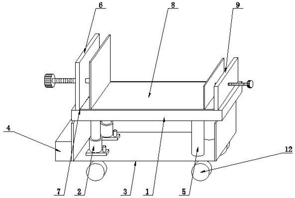
Fig. 1 is a schematic structural view of an automatic guided vehicle suitable for logistics;
FIG. 2 is a schematic view of the wheel mounting of a robotic guided vehicle adapted for logistics;
fig. 3 is a schematic structural diagram of a first clamping device and a buffer device in an automatic guided vehicle suitable for logistics;
fig. 4 is a schematic top view of a track in a automated guided vehicle for logistics;
fig. 5 is a schematic structural diagram of a guidance module in an automated guided vehicle suitable for logistics;
fig. 6 is a schematic structural view of a light receiving module in an automated guided vehicle suitable for logistics.
Detailed Description
Referring to fig. 1 to 6, in an embodiment of the present invention, an automatic guided vehicle suitable for logistics includes a frame 10, a vehicle head 4, axles 11, wheels 12, a rail, a guide module, a buffer module, and a clamping module, wherein the bottom of the frame is provided with at least two axles 11, the two ends of each axle are provided with the wheels 12, and the wheels are driven by a driving assembly, and is characterized in that the frame is provided with the buffer module, and the buffer module performs buffer shock absorption on articles on the frame;
the clamping module is used for automatically clamping and fixing articles on the frame;
guide modules which interact with each other are arranged on the bottom wall of the head 4 at the front end of the frame and the track of the guide vehicle;
the guide module comprises a light receiving module, a first track light-emitting strip assembly 13, a second track light-emitting strip assembly 15, a third track light-emitting strip assembly 14 and a direction controller, wherein,
the track is provided with a first track light-emitting strip assembly 13, a second track light-emitting strip assembly 15 and a third track light-emitting strip assembly 14 at equal intervals along the extending direction of the track, and the light receiving module is arranged on the bottom wall of the locomotive 4;
the light receiving module can respectively receive and identify the position information of the track light-emitting strip assembly I, the track light-emitting strip assembly II and the track light-emitting strip assembly III 14 irradiated on the light receiving module;
the direction controller can calculate according to the position information irradiated on the light receiving module and can control and adjust the direction controller according to the deviation degree of the actual position information from the standard position so as to enable the light receiving module to always run within the specified deviation range on the track;
the position of the intersection on the track is also provided with an intersection information electronic tag 16 representing the position information of the intersection, the bottom wall of the vehicle head is provided with a tag recognizer 18 for recognizing the intersection information electronic tag 16, and the tag recognizer 18 is in control connection with the direction controller so as to control the driving direction of the guided vehicle according to the recognition condition of the tag recognizer 18 and a set route in the guided vehicle.
In this embodiment, when the direction controller controls and adjusts the direction controller according to the deviation degree of the actual position information from the standard position, the deviation degree is an average value of the deviation degree of the first track light-emitting strip assembly, the deviation degree of the second track light-emitting strip assembly and the deviation degree of the third track light-emitting strip assembly received by the light receiving module, and the light intensities emitted by the first track light-emitting strip assembly 13, the second track light-emitting strip assembly 15 and the third track light-emitting strip assembly 14 are sequentially reduced, and the light receiving module determines whether the received light is from the first track light-emitting strip assembly, the second track light-emitting strip assembly or the third track light-emitting strip assembly according to the received light intensity signal.
As a preferred embodiment, the first track light-emitting strip assembly, the second track light-emitting strip assembly and the third track light-emitting strip assembly have the same structure, and each track light-emitting strip assembly includes a track base 21, a track body 20 and a vertical light-emitting strip 22, wherein the track base 21 is fixedly disposed on the track body 20, three mounting grooves 24 are disposed on the track body 20 along the extending direction of the track, a set of vertical light-emitting strips extending along the extending direction of the track are mounted in each mounting groove 24, a light-emitting end 25 of the vertical light-emitting strip 22 emits light in the vertically upward direction, a strip-shaped slit 26 extending along the track direction is disposed on the track body 20 above the center of the vertical light-emitting strip, and the light emitted by the vertical light-emitting strip irradiates the light-receiving module vertically upward from the strip-shaped slit 26.
The light receiving module comprises a mounting disc 19 and k light receiving probes 23 which are arranged on the mounting disc 19 and are arranged next to each other at equal intervals along the width direction of a track, wherein k is an integer larger than 12, light emitted by the vertical light emitting strip vertically and upwards irradiates the light receiving probes 23 from the strip-shaped slits, each light receiving probe 23 is in signal connection with the direction controller, position information of each light receiving probe 23 and a standard position of the light receiving probe capable of receiving the light information are stored in the direction controller, and the direction controller judges the deviation degree according to the position information of the light receiving probe capable of receiving the light emitted by the vertical light emitting strip.
In addition, in order to ensure the receiving accuracy, the luminous intensity of the vertical luminous strip of the first track luminous strip assembly 13 is at least twice as high as that of the vertical luminous strip of the second track luminous strip assembly 15, and the luminous intensity of the vertical luminous strip of the second track luminous strip assembly 15 is at least twice as high as that of the vertical luminous strip of the third track luminous strip assembly 14
In this embodiment, the clamping assembly includes a support plate 1, a first clamping device 6 and a second clamping device 9, wherein the bottom of the support plate 1 is fixedly connected with an electric lifter 2, and the bottom of the support plate 1 is close to a fixed column 5 fixed at a position of one side of the electric lifter 2, the bottom of the electric lifter 2 is welded with a bottom plate 3, the side wall of the bottom plate 3 is fixedly connected with a headstock 4, and the bottom of the bottom plate 3 is welded on a frame 10, the first clamping device 6 is arranged on one side of the top of the support plate 1, and the second clamping device 9 is arranged at a position of the other side of the top of the support plate 1 opposite to the first clamping device 6, a groove 7 is formed in the support plate 1, and a buffer device 8 is arranged in the groove 7.
In the invention, the model of the electric lifter 2 is ZTHT10001, and the arrangement of the electric lifter 2 can automatically unload the articles carried by the carrier plate 1, thereby reducing the workload of users, enhancing the working efficiency of the automatic guided vehicle, and preventing the automatic guided vehicle from being damaged when colliding by the arrangement of the vehicle head 4.
The first clamping device 6 comprises a guide seat 61, a driving rod 62, a moving block 63, a fixed block 64, a rubber pad 65 and a driving cylinder 66, the driving cylinder is fixed on the frame or the carrier plate 1 through a cylinder frame, the guide seat 61 is embedded in the side wall of the fixed block 64, the driving rod 62 is slidably installed in the guide seat 61, the moving block 63 is fixedly connected to one side of the driving rod 62, the other side of the driving rod 62 is connected to the piston rod of the driving cylinder 66, the rubber pad 65 is bonded to the side wall of the moving block 63, and through the arrangement of the first clamping device 6 and the second clamping device 9, articles can be clamped and fixed in the moving process, the articles are prevented from falling carelessly, and the practicability of the automatic guided vehicle is enhanced.
Recess 7 has been seted up to the inside of support plate 1, the inside of recess 7 is provided with buffer 8, buffer 8 includes the movable plate 81, gag lever post 82, branch 83, buffer 84 and spring 85, the bottom fixedly connected with branch 83 of movable plate 81, and the upper surface embedding of movable plate 81 installs gag lever post 82, one side position department fixedly connected with spring 85 that the bottom of movable plate 81 is close to branch 83, buffer 84 is installed to the bottom below of branch 83, buffer 84 is the component of sponge material, and buffer 84's thickness is 2-10cm, through buffer 8's setting, can cushion the vibrations that article received at the removal in-process, it receives the damage to place article, the stability of this automated guided vehicle has been strengthened.
The working principle of the invention is as follows: firstly, articles are placed in a movable plate 81 on a carrier plate 1, a driving motor 66 drives a threaded rod 62 to rotate so as to drive a movable block 63 to move, a first clamping device 6 and a second clamping device 9 are matched for use to clamp the articles, the friction force contacting with the articles is increased through a rubber pad 65, the articles can be clamped and fixed in the moving process through the arrangement of the first clamping device 6 and the second clamping device 9, the articles are prevented from falling carelessly, the practicability of the automatic guided vehicle is enhanced, when jolting occurs in the moving process, the movable plate 81 is subjected to pressure reduction due to the fact that the articles are placed on the movable plate 81 in a buffer device 8, the limiting rod 82 is used for limiting, a spring 85 is contracted, a support rod 83 at the moment is abutted downwards against a buffer gasket 84, the two are matched for use, and the shock on the articles in the moving process can be buffered through the arrangement of the buffer device 8, the placed articles are damaged, and the stability of the automatic guided vehicle is enhanced.
During automatic guidance, the light receiving module can respectively receive and identify position information of the track light-emitting strip assembly I, the track light-emitting strip assembly II and the track light-emitting strip assembly III 14, which are irradiated on the light receiving module; the direction controller can calculate according to the position information irradiated on the light receiving module and can control and adjust the direction controller according to the deviation degree of the actual position information from the standard position so as to enable the light receiving module to always run within the specified deviation range on the track; when the guidance meets the intersection for turning, an intersection information electronic tag 16 representing the position information of the intersection is arranged at the position of the intersection passing through the track, a tag recognizer 18 for recognizing the intersection information electronic tag 16 is arranged on the bottom wall of the vehicle head, and the tag recognizer 18 is in control connection with the direction controller so as to control the driving direction of the guidance vehicle according to the recognition condition of the tag recognizer 18 and the set route in the guidance vehicle.
When the automatic guided vehicle is used for unloading goods, the first clamping device 6 and the second clamping device 9 loosen the goods, the electric lifter 2 extends to lift the left side of the support plate 1, and the right side of the support plate 1 is kept still, so that the goods slide down from the support plate 1, and the goods loaded on the support plate 1 can be automatically unloaded through the arrangement of the electric lifter 2, so that the workload of a user is reduced, and the working efficiency of the automatic guided vehicle is enhanced.
The above description is only for the preferred embodiment of the present invention, but the scope of the present invention is not limited thereto, and any person skilled in the art should be considered to be within the technical scope of the present invention, and the technical solutions and the inventive concepts thereof according to the present invention are equivalent to or changed within the technical scope of the present invention.