CN109514630B - Material cutting device - Google Patents
Material cutting device Download PDFInfo
- Publication number
- CN109514630B CN109514630B CN201811414109.4A CN201811414109A CN109514630B CN 109514630 B CN109514630 B CN 109514630B CN 201811414109 A CN201811414109 A CN 201811414109A CN 109514630 B CN109514630 B CN 109514630B
- Authority
- CN
- China
- Prior art keywords
- groove
- positioning
- rotating shaft
- fixed
- blanking device
- Prior art date
- Legal status (The legal status is an assumption and is not a legal conclusion. Google has not performed a legal analysis and makes no representation as to the accuracy of the status listed.)
- Expired - Fee Related
Links
- 238000005520 cutting process Methods 0.000 title claims abstract description 70
- 239000000463 material Substances 0.000 title claims abstract description 38
- 241000157352 Uncaria Species 0.000 claims abstract description 40
- 230000007246 mechanism Effects 0.000 description 9
- 230000005540 biological transmission Effects 0.000 description 6
- 241000157373 Uncaria rhynchophylla Species 0.000 description 4
- 230000009471 action Effects 0.000 description 4
- 230000005484 gravity Effects 0.000 description 3
- 238000000034 method Methods 0.000 description 3
- 235000014787 Vitis vinifera Nutrition 0.000 description 2
- 240000006365 Vitis vinifera Species 0.000 description 2
- 230000008569 process Effects 0.000 description 2
- 241000345998 Calamus manan Species 0.000 description 1
- 230000009286 beneficial effect Effects 0.000 description 1
- 239000011111 cardboard Substances 0.000 description 1
- 238000010586 diagram Methods 0.000 description 1
- 238000004519 manufacturing process Methods 0.000 description 1
- 230000004048 modification Effects 0.000 description 1
- 238000012986 modification Methods 0.000 description 1
- 235000012950 rattan cane Nutrition 0.000 description 1
- 238000005096 rolling process Methods 0.000 description 1
- 239000004065 semiconductor Substances 0.000 description 1
- 230000032258 transport Effects 0.000 description 1
- 238000009966 trimming Methods 0.000 description 1
Images


Classifications
-
- B—PERFORMING OPERATIONS; TRANSPORTING
- B26—HAND CUTTING TOOLS; CUTTING; SEVERING
- B26D—CUTTING; DETAILS COMMON TO MACHINES FOR PERFORATING, PUNCHING, CUTTING-OUT, STAMPING-OUT OR SEVERING
- B26D1/00—Cutting through work characterised by the nature or movement of the cutting member or particular materials not otherwise provided for; Apparatus or machines therefor; Cutting members therefor
- B26D1/01—Cutting through work characterised by the nature or movement of the cutting member or particular materials not otherwise provided for; Apparatus or machines therefor; Cutting members therefor involving a cutting member which does not travel with the work
- B26D1/12—Cutting through work characterised by the nature or movement of the cutting member or particular materials not otherwise provided for; Apparatus or machines therefor; Cutting members therefor involving a cutting member which does not travel with the work having a cutting member moving about an axis
- B26D1/25—Cutting through work characterised by the nature or movement of the cutting member or particular materials not otherwise provided for; Apparatus or machines therefor; Cutting members therefor involving a cutting member which does not travel with the work having a cutting member moving about an axis with a non-circular cutting member
- B26D1/26—Cutting through work characterised by the nature or movement of the cutting member or particular materials not otherwise provided for; Apparatus or machines therefor; Cutting members therefor involving a cutting member which does not travel with the work having a cutting member moving about an axis with a non-circular cutting member moving about an axis substantially perpendicular to the line of cut
- B26D1/28—Cutting through work characterised by the nature or movement of the cutting member or particular materials not otherwise provided for; Apparatus or machines therefor; Cutting members therefor involving a cutting member which does not travel with the work having a cutting member moving about an axis with a non-circular cutting member moving about an axis substantially perpendicular to the line of cut and rotating continuously in one direction during cutting
-
- B—PERFORMING OPERATIONS; TRANSPORTING
- B26—HAND CUTTING TOOLS; CUTTING; SEVERING
- B26D—CUTTING; DETAILS COMMON TO MACHINES FOR PERFORATING, PUNCHING, CUTTING-OUT, STAMPING-OUT OR SEVERING
- B26D7/00—Details of apparatus for cutting, cutting-out, stamping-out, punching, perforating, or severing by means other than cutting
- B26D7/01—Means for holding or positioning work
-
- B—PERFORMING OPERATIONS; TRANSPORTING
- B26—HAND CUTTING TOOLS; CUTTING; SEVERING
- B26D—CUTTING; DETAILS COMMON TO MACHINES FOR PERFORATING, PUNCHING, CUTTING-OUT, STAMPING-OUT OR SEVERING
- B26D7/00—Details of apparatus for cutting, cutting-out, stamping-out, punching, perforating, or severing by means other than cutting
- B26D7/06—Arrangements for feeding or delivering work of other than sheet, web, or filamentary form
-
- B—PERFORMING OPERATIONS; TRANSPORTING
- B27—WORKING OR PRESERVING WOOD OR SIMILAR MATERIAL; NAILING OR STAPLING MACHINES IN GENERAL
- B27J—MECHANICAL WORKING OF CANE, CORK, OR SIMILAR MATERIALS
- B27J1/00—Mechanical working of cane or the like
Landscapes
- Life Sciences & Earth Sciences (AREA)
- Forests & Forestry (AREA)
- Engineering & Computer Science (AREA)
- Mechanical Engineering (AREA)
- Nonmetal Cutting Devices (AREA)
- Making Paper Articles (AREA)
Abstract
The invention provides a blanking device for blanking uncaria. The uncaria comprises a straight strip and a hook part arranged on the straight strip. The cutting device comprises a rack, a driving piece, a rotating shaft, a plurality of cutting blades, a cutter groove piece and a positioning piece. The driving part and the cutter groove part are fixed on the frame. The rotating shaft is connected with the driving piece. The plurality of cutting blades are arranged on the rotating shaft at intervals, and the cutting edges of the cutting blades are not on the same plane. The cutter groove piece is concavely provided with a positioning groove corresponding to each material cutting blade. The cutter groove piece is provided with a feeding channel communicated with each cutter groove. The cutter groove part is concavely provided with a positioning groove which is positioned between the two cutter grooves. The positioning piece is rotatably arranged on the frame. The positioning piece is concavely provided with a groove which can be selectively accommodated in the positioning groove. When the groove is contained in the positioning groove, a limiting groove is formed between the groove and the positioning groove, the straight strip can pass through the limiting groove, the hook part cannot pass through the limiting groove, and at the moment, the driving part drives the rotating shaft to rotate so as to drive the cutting blade to cut off the straight strip.
Description
[ technical field ] A method for producing a semiconductor device
The invention relates to the technical field of machinery, in particular to a material cutting device.
[ background of the invention ]
The uncaria comprises straight strips and hook parts arranged on the straight strips at intervals, the hook parts on the uncaria and the straight strips need to be cut off and separated in the using process, and the straight strips are segmented. According to the traditional method, the uncaria is manually cut by using a material cutting scissors manually so as to cut off straight strips and hook parts on the uncaria and manually segment the straight strips. For improving artifical blank inefficiency problem, adopt mechanical blank device to carry out the blank at present, this blank device includes conveyer belt and blank sword, and the conveyer belt is used for transporting the uncaria, and the blank sword is used for carrying out the blank to the uncaria. In this blank operation, need the start and stop of manual control conveyer belt, when the conveyer belt transported the uncaria to under the blank sword, the manual work stops the conveyer belt, and the blank sword carries out the blank, and the back is accomplished in the blank, opens the conveyer belt, transports the material to the assigned position. In the process, whether the uncaria is sent to the material cutting knife or not is manually confirmed, errors easily exist, if the uncaria is in a large place, the hook part is easily cut by the material cutting knife, and the errors between the materials cut out every time are large.
[ summary of the invention ]
In view of the above problems, it is necessary to provide a cutting device capable of positioning a grapevine when the grapevine is cut.
In order to achieve the purpose, the technical scheme adopted by the invention is as follows:
a kind of blank device, is used for carrying on the blank to the uncaria, this uncaria includes the straight strip and hook department set in this straight strip, this blank device includes stander, driving piece, axis of rotation, blank blade group and knife slot component, this driving piece and this knife slot component are fixed on this stander, this axis of rotation is connected with this driving piece, this blank blade group includes a plurality of blank blades, a plurality of this blank blades are installed on this axis of rotation at intervals, and the cutting edge of the blank blade is not on the identity level, the notch component is concave to form and has the locating slot corresponding to each this blank blade one by one, there is a feed channel on the knife slot component, this feed channel communicates with each this knife slot, this knife slot component is concave to have locating slot, this locating slot locates between two this knife slots, this blank device also includes the locating element rotatably mounted on this stander, concave to form a recess on this locating slot, this recess can be selectively accommodated in this locating slot, when the groove is accommodated in the positioning groove, a limiting groove is formed between the groove and the positioning groove, the straight strip can pass through the limiting groove, the hook part cannot pass through the limiting groove, and at the moment, the driving part drives the rotating shaft to rotate so as to drive each cutting blade to cut off the straight strip.
Preferably, the blanking device 100 further comprises a bearing seat 313, the bearing seat 313 is fixed on the frame 10, and the rotating shaft 314 is mounted on the bearing seat 313.
Preferably, the blanking device 100 further comprises a driving wheel 312 and a driven wheel 315, wherein the driving wheel 312 is fixed on the driving element 311, the driven wheel 315 is fixed on the rotating shaft 314, and the driven wheel 315 is meshed with the driving wheel 312.
Preferably, the material cutting device 100 further includes a driving wheel 312, a driven wheel 315 and a transmission belt 316, wherein the driving wheel 312 is fixed on the driving element 311, the driven wheel 315 is fixed on the rotating shaft 314, and the transmission belt 316 is sleeved on the driving wheel 312 and the driven wheel 315.
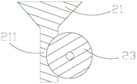
Preferably, the blanking device 100 further comprises a hopper 21 and a feeding roller 23 mounted on the frame 10, the feeding roller 23 is partially accommodated in the hopper 21, a feeding channel 211 is formed between the feeding roller 23 and the hopper 21, and the feeding channel 211 is located above the feeding channel 3371.
Preferably, the cutting device 100 further includes a first mounting member 331 and a second mounting member 335, the first mounting member 331 is fixed to the rotating shaft 314, each of the cutting blades 3331 is fixed to the first mounting member 331 at an equal interval, the second mounting member 335 is fixed to the frame 10, and the blade 337 is fixed to the second mounting member 335.
Preferably, the plurality of blanking blades 3331 are fixed to the first mounting member 331 at equal intervals.
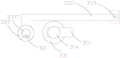
Preferably, the material cutting device 100 further includes a pushing element 351 having one end fixed to the rotating shaft 314, when the groove 3521 of the positioning element 352 is received in the positioning slot 3375, a distance between the end of the pushing element 351 away from the rotating shaft 314 and the rotating shaft 314 is greater than a vertical distance between the positioning element 352 and the rotating shaft 314, and after the material cutting is completed, the rotating shaft 314 drives the pushing element 351 to push the positioning element 352 to move so that the end of the positioning element 352 close to the groove 3521 moves toward a direction away from the positioning slot 3375.
Preferably, the blanking device 100 further comprises a latch shaft 353, the positioning member 352 is rotatably mounted on the frame 10 via the latch shaft 353, and a return spring is disposed in the latch shaft 353.
Preferably, the positioning groove 3375 is located between the first knife slot 3373 and the knife slot 3373 adjacent to the first knife slot 3373.
Due to the adoption of the technical scheme, the invention has the following beneficial effects:
the groove of the positioning piece in the cutting device can be selectively contained in the positioning groove, and when the groove of the positioning piece is contained in the positioning groove, a limit groove is formed between the groove and the positioning groove. The size of the limiting groove is not enough for the hook part to pass through and the straight strips to pass through, so that the uncaria can be automatically positioned when the groove of the positioning piece is accommodated in the positioning groove, and the straight strips of the uncaria are cut off by the material cutting blade when the uncaria is in a positioning state; the device can also reduce the loss of the cutting-free mechanism and prolong the service life of the instrument.
[ description of the drawings ]
Fig. 1 is a front view of a blanking device according to a preferred embodiment of the present invention.
Fig. 2 is a schematic front view of the cutting device shown in fig. 1 when cutting the hooked rattan.
Fig. 3 is a cross-sectional view of the feed assembly in the blanking device shown in fig. 1, taken along the axis of the hopper.
Fig. 4 is a schematic structural diagram of a driving assembly in the blanking device shown in fig. 1.
Fig. 5 is an exploded view of a blanking assembly of the blanking device shown in fig. 1.
Fig. 6 is a top view of the blanking assembly shown in fig. 5.
Fig. 7 is a schematic top view of the positioning assembly, the rotating shaft, the first mounting member and the knife channel member of the cutting device shown in fig. 1.
Fig. 8 is a schematic top view of the positioning assembly, the rotating shaft, the first mounting member and the knife channel member when the pushing member pushes the positioning member to move.
Description of the main elements
In the drawing, 100-material cutting device, 200-uncaria, 201-straight strip, 203-hook part, 10-frame, 20-feeding component, 21-hopper, 211-feeding channel, 23-feeding roller, 30-material cutting mechanism, 31-driving component, 311-driving component, 312-driving wheel, 313-bearing seat, 314-rotating shaft, 315-driven wheel, 316-conveying belt, 33-material cutting component, 331-first mounting component, 333-material cutting blade group, 3331-material cutting blade, 335-second mounting component, 337-knife groove component, 3371-feeding channel, 3373-knife groove, 3375-positioning groove, 35-positioning component, 351-driving component, 352-positioning component, 3521-groove, 353-card plate shaft, 301-a retaining groove.
[ detailed description ] embodiments
The technical solutions in the embodiments of the present invention will be clearly and completely described below with reference to the drawings in the embodiments of the present invention, and it is obvious that the described embodiments are only a part of the embodiments of the present invention, and not all of the embodiments. All other embodiments, which can be derived by a person skilled in the art from the embodiments given herein without making any creative effort, shall fall within the protection scope of the present invention.
It will be understood that when an element is referred to as being "secured to" another element, it can be directly on the other element or intervening elements may also be present. When a component is referred to as being "connected" to another component, it can be directly connected to the other component or intervening components may also be present. When a component is referred to as being "disposed on" another component, it can be directly on the other component or intervening components may also be present. The terms "vertical," "horizontal," "left," "right," and the like as used herein are for illustrative purposes only.
Unless defined otherwise, all technical and scientific terms used herein have the same meaning as commonly understood by one of ordinary skill in the art to which this invention belongs. The terminology used in the description of the invention herein is for the purpose of describing particular embodiments only and is not intended to be limiting of the invention. As used herein, the term "and/or" includes any and all combinations of one or more of the associated listed items.
Referring to fig. 1 and 2, a preferred embodiment of the present invention provides a material cutting device 100, wherein the material cutting device 100 is used for cutting an uncaria hook 200. In this embodiment, the uncaria 200 includes a straight bar 201 and a plurality of hooks 203 equidistantly disposed on the straight bar 201. When the trimming device 100 trims the uncaria hook 200, the straight line 201 and the hook 203 of the uncaria hook 200 are cut and the straight line 201 is segmented. The blanking device 100 comprises a frame 10, a feeding assembly 20 and a blanking mechanism 30. The feeding assembly 20 and the blanking mechanism 30 are both mounted on the frame 10. The feeding assembly 20 is disposed adjacent to the blanking mechanism 30. The feeding assembly 20 is used for feeding the uncaria 200 into the blanking mechanism 30. The material cutting mechanism 30 is used for cutting the uncaria 200 to cut the straight strips 201 and the hook portions 203 on the uncaria 200 and segmenting the straight strips 201.
Referring to fig. 3, the feeding assembly 20 includes a hopper 21 and a feeding roller 23. The hopper 21 is fixedly mounted on the frame 10. The feed roller 23 is rotatably mounted on the frame 10 and the feed roller 23 is partially received in the hopper 21. The gap between the feed roller 23 and the feed hopper 21 forms a feed channel 211. The feeding roller 23 can feed the uncaria 200 into the cutting mechanism 30 from the feeding channel 211 in the rolling process.
The material cutting mechanism 30 includes a driving assembly 31, a material cutting assembly 33 and a positioning assembly 35. The drive assembly 31 is mounted on the frame 10. The blanking assembly 33 is connected to the drive assembly 31. The positioning assembly 35 is disposed adjacent to the driving assembly 31 and the blanking assembly 33. Referring to fig. 4, the driving assembly 31 includes a driving member 311, a driving wheel 312, a bearing seat 313, a rotating shaft 314, a driven wheel 315, and a transmission belt 316. The driving member 311 is fixed to the frame 10, and the driving wheel 312 is mounted on the driving end of the driving member 311. The bearing housing 313 is fixed to the frame 10, and the rotating shaft 314 is rotatably mounted to the bearing housing 313. The driven pulley 315 is fixed to one end of the rotating shaft 314. The belt 316 is disposed on the driving wheel 312 and the driven wheel 315. When the driving member 311 drives the driving wheel 312 to rotate, the driving wheel 312 drives the driven wheel 315 to rotate through the transmission belt 316, thereby driving the rotating shaft 314 to rotate. In this embodiment, the driver 311 is a motor.
Referring to fig. 5 and 6, the blanking assembly 33 is disposed near an end of the rotating shaft 314 away from the driven wheel 315. The cutting assembly 33 includes a first mounting member 331, a cutting blade set 333, a second mounting member 335, and a knife channel 337. The first mounting member 331 is fixedly mounted to an end of the rotating shaft 314 remote from the driven wheel 315. The blanking blade set 333 is fixed to the first mounting member 331. In the present embodiment, the cutter blade group 333 includes 5 cutter blades 3331. Each blanking blade 3331 is fixed perpendicular to the rotating shaft 314, and the cutting edge of each blanking blade 3331 is perpendicular to the rotating direction of the rotating shaft 314. In this embodiment, the 5 blanking blades 3331 are spirally spaced on the first mounting member 331, that is, the connecting line of the ends of the blanking blades 3331 is not parallel to the rotation axis direction of the rotation shaft 314, and the cutting edge directions of the blanking blades 3331 are not on the same plane. That is, the line connecting the ends of the 5-piece dicing blade 3331 is neither parallel nor perpendicular to the axis of the rotary shaft 314. The vertical distances between the 5-piece blanking blades 3331 are the same in the direction of the rotation axis of the rotation shaft 314. When the rotating shaft 314 rotates, the rotating shaft 314 drives the 5-piece slicing blade 3331 to rotate around the rotating shaft of the rotating shaft 314. The second mounting member 335 is secured to the frame 10 and the pocket 337 is secured to the second mounting member 335. The knife slot 337 is substantially cylindrical. The hollow portion of the knife channel piece 337 in the axial direction forms a feed channel 3371, and the feed channel 3371 is located directly below the feed channel 211 so that the feed roller 23 feeds the uncaria 200 from the feed channel 211 into the feed channel 3371. A knife groove 3373 corresponding to each of the cutting blades 3331 is concavely formed on the circumferential surface of the knife groove member 337 toward the axial direction of the vertical knife groove member 337 to such a depth that the knife groove 3373 completely includes the transverse section hole of the feed channel 3371. In the present embodiment, the number of the knife grooves 3373 is 5 so as to correspond one-to-one to each of the blanking blades 3331. The circumferential surface of the knife slot group 337 is concavely provided with a positioning groove 3375 along the axial direction of the vertical knife slot member 337, and the positioning groove 3375 is positioned between the first knife slot 3373 and the knife slot 3373 adjacent to the first knife slot 3373. The positioning groove 3375 is vertically communicated with the feeding channel 3371.
Referring to fig. 7-8, the positioning assembly 35 is disposed adjacent to the rotation shaft 314 and the knife slot 337. The positioning assembly 35 includes a pusher 351, a positioning member 352, and a chuck shaft 353. One end of the pushing element 351 is fixedly mounted on the rotating shaft 314, and drives the pushing element 351 to rotate around the rotating shaft 314 along with the rotating shaft 314 when the rotating shaft 314 rotates. The positioning member 352 is substantially L-shaped, one end of the positioning member 352 is rotatably mounted on the frame 10 through a clamping plate shaft 353, and the clamping plate shaft 353 and the knife groove 337 are located at two sides of the rotating shaft 314. A return spring (not shown) is provided in the chucking shaft 353. The positioning member 352 is recessed with a groove 3521 at an end thereof away from the chuck shaft 353. In this embodiment, when the return spring is in a natural state, the vertical distance between the positioning element 352 and the rotating shaft 314 is smaller than the distance from the pushing element 351 to the rotating shaft 314 away from the rotating shaft 314, one end of the positioning element 352 close to the groove 3521 is accommodated in the positioning slot 3375, and the gap formed between the groove 3521 and the positioning slot 3375 is smaller than the size of the hook 203 and larger than the size of the straight bar 201, so that the hook 203 cannot pass through but the straight bar 201 can pass through. In this embodiment, when the return spring is in a natural state, the gap formed between the groove 3521 and the positioning groove 3375 is defined as the limiting groove 301, and the limiting groove 301 is located right below the feeding channel 211. When the rotating shaft 314 rotates, the pushing element 351 is driven to rotate, and since the vertical distance between the positioning element 352 and the rotating shaft 314 is smaller than the distance from the pushing element 351 to the rotating shaft 314 from the rotating shaft 314, the pushing element 351 can push the positioning element 352 to move towards the direction away from the positioning slot 3375 after the pushing element 351 contacts the positioning element 352, so that the return spring is elongated. After the pushing element 351 rotates over the positioning element 352, the positioning element 352 returns to the natural state under the action of the return spring.
During assembly, the hopper 21 is fixedly mounted on the frame 10, the feeding roller 23 is rotatably mounted on the frame 10, the feeding roller 23 is partially accommodated in the hopper 21, and a feeding channel 211 is formed by a gap between the feeding roller 23 and the hopper 21. The driving member 311 and the bearing holder 313 are fixed to the frame 10. The drive wheel 312 is attached to the drive end of the drive member 311, and the rotating shaft 314 is rotatably attached to the bearing housing 313. The driven pulley 315 is fixed to one end of the rotating shaft 314, and the belt 316 is fitted over the driving pulley 312 and the driven pulley 315. The first mounting member 331 is fixed to the rotating shaft 314, and the 5-piece blanking blade 3331 is fixed to the first mounting member 331, and the blanking blade edge direction of each blanking blade 3331 is perpendicular to the rotating direction of the rotating shaft 314. The second mounting member 335 is fixed to the frame 10, the knife channel member 337 is fixed to the second mounting member 335 such that the feeding channel 3371 of the knife channel member 337 is positioned directly below the feeding channel 211, and each knife channel 3373 of the knife channel member 337 corresponds to a corresponding cutting blade 3331. The pushing element 351 is fixed on the rotating shaft 314, and one end of the positioning element 352 away from the groove 3521 is rotatably mounted on the frame 10 through the clamping plate shaft 353, and one end of the positioning element 352 close to the groove 3521 can selectively extend into the positioning slot 3375 of the knife slot element 337.
When the uncaria rhynchophylla feeding device is used, one end of the uncaria rhynchophylla 200 is placed into the feeding hopper 21, and the straight strips 201 of the uncaria rhynchophylla 200 enter the feeding channel 3371 from the feeding channel 211 under the action of the feeding roller 23. The driving member 311 drives the driving wheel 312 to rotate, and the driving wheel 312 drives the driven wheel 315 to rotate through the transmission belt 316, thereby driving the rotating shaft 314 to rotate. When the rotating shaft 314 rotates, the material cutting blade set 333 and the pusher 351 rotate in the rotating shaft direction of the rotating shaft 314 as the rotating shaft 314 rotates. When the hook 203 of the hook 200 is sent to the positioning slot 3375, the return spring is in a natural state, the pushing element 351 does not push the positioning element 352, the groove 3521 is accommodated in the positioning slot 3375, and a limiting groove 301 is formed between the groove and the positioning slot 3375, at this time, the straight bar 201 can pass through the limiting groove 301, and the hook 203 cannot pass through. When the hook 203 of the uncaria hook 200 is sent to the positioning groove 3375, the uncaria hook 200 is snap-positioned because the hook 203 of the uncaria hook 200 cannot pass through the stopper groove 301. The rotation of the rotating shaft 314 rotates the cutter blade set 333, so that each cutter blade 3331 cuts the straight strip 201 of the uncaria rhynchophylla 200. Since the positioning groove 3375 is located between the first knife slot 3373 and the knife slot 3373 adjacent to the first knife slot 3373, the first cutting blade 3331 and the adjacent cutting blade 3331 are cut off the straight strips 201 on both sides of the hook 203 which are positioned by the limiting groove 301 in a snapping manner. After the blanking blade group 333 performs blanking, the cut straight bar 201 falls. Referring to fig. 8 again, after the material cutting is completed, the rotating shaft 314 continues to drive the material cutting blade 3331 and the pushing element 351 to rotate, when the rotating shaft 314 drives the pushing element 351 to rotate until the pushing element 351 contacts the positioning element 352, because the vertical distance between the positioning element 352 and the rotating shaft 314 is smaller than the distance between the pushing element 351 and the rotating shaft 314 far away from the rotating shaft 314, the pushing element 351 pushes one end of the positioning element 352 close to the groove 3521 to move towards the direction far away from the positioning slot 3375, so that the gap between the groove 3521 and the positioning slot 3375 is increased until the gap between the groove 3521 and the positioning slot 3375 is larger than the size of the hook 203, and the cut hook 203. When the rotating shaft 314 rotates the pushing member 351 past the positioning member 352, the pushing member 351 no longer pushes the positioning member 352. At this time, under the action of the return spring, the positioning element 352 returns to the natural state, the end of the positioning element 352 close to the groove 3521 is accommodated in the positioning groove 3375 again, and the limiting groove 301 is formed between the groove 3521 and the positioning groove 3375 again. The straight strips 201 of the rest uncaria 200 are sent into the feeding channel 3371 again by the feeding roller 23 until the hook part 203 is buckled and positioned by the limiting groove 301, the rotating shaft 314 drives the material cutting blade set 333 to cut the uncaria 200 again, and the cut straight strips 201 fall off. The pushing member 351 pushes the positioning member 352 to move away from the positioning groove 3375, and the cut-off hook portion 203 drops. The above-mentioned material cutting steps are repeated, so that all the uncaria 200 are completely cut by the material cutting assembly 33.
The groove 3521 of the positioning element 352 in the blanking device 100 of the present embodiment can be selectively received in the positioning slot 3375, and when the groove 3521 of the positioning element 352 is received in the positioning slot 3375, a spacing groove 301 is formed between the groove 3521 and the positioning slot 3375. The size of the limiting groove 301 is not enough for the hook part 203 of the uncaria 200 to pass through and the straight strip 201 to pass through, so that when the groove 3521 of the positioning piece 352 is accommodated in the positioning groove 3375, the uncaria 200 can be automatically positioned, and when the uncaria 200 is in a positioning state, the straight strip 201 of the uncaria 200 is cut off by the cutting blade 3331. Further, when the groove 3521 of the positioning element 352 is received in the positioning slot 3375, a distance between an end of the pushing element 351 away from the rotating shaft 314 and the rotating shaft 314 is greater than a vertical distance between the positioning element 352 and the rotating shaft 314. After the material cutting is completed, the rotating shaft 314 drives the pushing element 351 to push the positioning element 352 to move, so that one end of the positioning element 352 close to the groove 3521 moves in a direction away from the positioning slot 3375, and thus a gap between the groove 3521 and the positioning slot 3375 is enlarged, so that the cut hook 203 can fall off. In the present embodiment, the 5-piece slitting blade 3331 is provided spirally on the first mounting fixture 331, so that the impact of the slitting blade 3331 on the straight bars 201 can be reduced at the same time.
The rotating shaft 314 drives the pushing element 351 to rotate, and when the pushing element 351 does not push the positioning element 352 to move in a direction away from the rotating shaft 314, one end of the positioning element 352 close to the groove 3521 is accommodated in the positioning slot 3375, so that the limiting groove 301 is formed between the groove 3521 and the positioning slot 3375. Since the size of the limiting groove 301 is not enough for the hook part 203 to pass through and the straight bar 201 to pass through, the uncaria 200 can be automatically positioned before the pushing part 351 pushes the positioning part 352 to move towards the direction far away from the rotating shaft 314, so that the blanking blade 3331 cuts off the straight bar 201 of the uncaria 200 when the uncaria 200 is in the positioning state.
It is understood that in other embodiments, the feeding assembly 20 may be omitted and the hooked member 200 is manually fed into the feeding channel 3371.
It is understood that in other embodiments, the belt 316 may be omitted, and in this case, the driving wheel 312 and the driven wheel 315 may be gears, and the driving wheel 312 may be engaged with the driven wheel 315.
It is understood that in other embodiments, the driving wheel 312, the bearing seat 313, the driven wheel 315 and the transmission belt 316 of the driving assembly 31 can be omitted, and in this case, the rotating shaft 314 can be directly mounted on the driving end of the driving member 311.
It is understood that in other embodiments, the number of the blanking blades 3331 included in the blanking blade set 333 is not limited to 5 in this embodiment, and may be 2, 3, 4 or more than 5, and in this case, the knife grooves 3373 of the knife groove 337 correspond to the blanking blades 3331 one by one.
It is to be understood that in other embodiments, the first mounting member 331 may be omitted and the cutting blade set 333 may be directly fixed to the rotating shaft 314.
It will be appreciated that in other embodiments, the second mounting member 335 may be omitted and the knife slot 337 may be directly fixedly mounted to the frame 10.
It is to be understood that, in other embodiments, each of the blanking blades 3331 is not limited to be mounted on the first mounting member 331 in the embodiment, and the blanking blades 3331 may be fixed to the first mounting member 331 at equal intervals or at unequal intervals along the rotation axis direction of the rotation shaft 314, as long as the blanking blades 3331 are spaced apart and the edge directions of all the blanking blades 3331 are not on the same plane.
It is understood that in other embodiments, the return spring may be omitted, and when the groove 3521 of the positioning element 352 faces the gravity direction of the positioning element 352, the positioning element 352 can return to the natural state by the gravity of the positioning element 352, that is, when the pushing element 351 pushes the positioning element 352 to move away from the rotating shaft 314 until the pushing element 351 no longer pushes the positioning element 352, the positioning element 352 can rotate around the card board shaft 353 toward the rotating shaft 314 under the action of gravity, so that the end of the positioning element 352 close to the groove 3521 is accommodated in the positioning slot 3375 again.
It will be appreciated that in other embodiments, the pushing member 351 can be omitted, and after the material is cut, the positioning member 352 can be manually pushed to move the groove 3521 of the positioning member 352 away from the positioning slot 3375.
The above description is intended to describe in detail the preferred embodiments of the present invention, but the embodiments are not intended to limit the scope of the claims of the present invention, and all equivalent changes and modifications made within the technical spirit of the present invention should fall within the scope of the claims of the present invention.
Claims (10)
1. The utility model provides a blank device (100) for carry out the blank to uncaria (200), this uncaria (200) include straight strip (201) and set up hook portion (203) on this straight strip (201), this blank device (100) include frame (10), driving piece (311), axis of rotation (314), blank blade group (333) and sword groove spare (337), this driving piece (311) and this sword groove spare (337) are fixed in on this frame (10), this axis of rotation (314) are connected with this driving piece (311), its characterized in that: the material cutting blade set (333) comprises a plurality of material cutting blades (3331), a plurality of material cutting blades (3331) are arranged on the rotating shaft (314) at intervals, the cutting edges of the material cutting blades (3331) are not on the same plane, a cutter groove member (337) is concavely provided with cutter grooves (3373) corresponding to each material cutting blade (3331) one by one, a feed channel (3371) is arranged on the cutter groove member (337), the feed channel (3371) is communicated with each cutter groove (3373), a positioning groove (3375) is concavely arranged on the cutter groove member (337), the positioning groove (3375) is positioned between the two cutter grooves (3373), the material cutting device (100) further comprises a positioning member (352) rotatably arranged on the machine frame (10), a groove (3521) is concavely arranged on the cutter groove (352), the groove (3521) can be selectively accommodated in the positioning groove (3375), and when the positioning member (3375) is accommodated in the positioning groove (3521), a limiting groove (301) is formed between the groove (3521) and the limiting groove (3375), the straight strip (201) can pass through the limiting groove (301), the hook part (203) cannot pass through the limiting groove, and at the moment, the driving part (311) drives the rotating shaft (314) to rotate so as to drive each material cutting blade (3331) to cut off the straight strip (201).
2. The blanking device (100) according to claim 1, characterized in that: the blanking device (100) further comprises a bearing seat (313), the bearing seat (313) is fixed on the frame (10), and the rotating shaft (314) is mounted on the bearing seat (313).
3. The blanking device (100) according to claim 2, characterized in that: the cutting device (100) further comprises a driving wheel (312) and a driven wheel (315), the driving wheel (312) is fixed on the driving piece (311), the driven wheel (315) is fixed on the rotating shaft (314), and the driven wheel (315) is meshed with the driving wheel (312).
4. The blanking device (100) according to claim 2, characterized in that: the cutting device (100) further comprises a driving wheel (312), a driven wheel (315) and a conveying belt (316), the driving wheel (312) is fixed on the driving piece (311), the driven wheel (315) is fixed on the rotating shaft (314), and the conveying belt (316) is sleeved on the driving wheel (312) and the driven wheel (315).
5. The blanking device (100) according to claim 1, characterized in that: the blanking device (100) further comprises a feed hopper (21) and a feed roller (23) which are arranged on the rack (10), the feed roller (23) is partially accommodated in the feed hopper (21), a feed channel (211) is arranged between the feed roller (23) and the feed hopper (21), and the feed channel (211) is positioned above the feed channel (3371).
6. The blanking device (100) according to claim 1, characterized in that: the cutting device (100) further comprises a first mounting part (331) and a second mounting part (335), the first mounting part (331) is fixed on the rotating shaft (314), each cutting blade (3331) is fixed on the first mounting part (331) at equal intervals, the second mounting part (335) is fixed on the rack (10), and the knife groove part (337) is fixed on the second mounting part (335).
7. The blanking device (100) according to claim 6, characterized in that: the plurality of blanking blades (3331) are fixed to the first mounting member (331) at equal intervals.
8. The blanking device (100) according to claim 1, characterized in that: the cutting device (100) further comprises a pushing element (351) with one end fixed on the rotating shaft (314), when the groove (3521) of the positioning element (352) is accommodated in the positioning groove (3375), the distance between one end of the pushing element (351) far away from the rotating shaft (314) and the rotating shaft (314) is larger than the vertical distance between the positioning element (352) and the rotating shaft (314), and after the cutting is finished, the rotating shaft (314) drives the pushing element (351) to push the positioning element (352) to move so that one end of the positioning element (352) close to the groove (3521) moves towards the direction far away from the positioning groove (3375).
9. The blanking device (100) according to claim 1, characterized in that: the blanking device (100) further comprises a clamping plate shaft (353), the positioning piece (352) is rotatably arranged on the rack (10) through the clamping plate shaft (353), and a return spring is arranged in the clamping plate shaft (353).
10. The blanking device (100) according to claim 1, characterized in that: the positioning groove (3375) is located between the first knife groove (3373) and the knife groove (3373) adjacent to the knife groove (3373).
Priority Applications (1)
| Application Number | Priority Date | Filing Date | Title |
|---|---|---|---|
| CN201811414109.4A CN109514630B (en) | 2018-11-26 | 2018-11-26 | Material cutting device |
Applications Claiming Priority (1)
| Application Number | Priority Date | Filing Date | Title |
|---|---|---|---|
| CN201811414109.4A CN109514630B (en) | 2018-11-26 | 2018-11-26 | Material cutting device |
Publications (2)
| Publication Number | Publication Date |
|---|---|
| CN109514630A CN109514630A (en) | 2019-03-26 |
| CN109514630B true CN109514630B (en) | 2020-09-25 |
Family
ID=65778805
Family Applications (1)
| Application Number | Title | Priority Date | Filing Date |
|---|---|---|---|
| CN201811414109.4A Expired - Fee Related CN109514630B (en) | 2018-11-26 | 2018-11-26 | Material cutting device |
Country Status (1)
| Country | Link |
|---|---|
| CN (1) | CN109514630B (en) |
Families Citing this family (1)
| Publication number | Priority date | Publication date | Assignee | Title |
|---|---|---|---|---|
| CN109514629B (en) * | 2018-11-26 | 2020-09-25 | 广西融安县树发生态农业发展有限公司 | Material cutting device and material cutting method |
Citations (5)
| Publication number | Priority date | Publication date | Assignee | Title |
|---|---|---|---|---|
| JPS4847679A (en) * | 1971-10-20 | 1973-07-06 | ||
| JPS50115897U (en) * | 1974-03-05 | 1975-09-20 | ||
| CN105364970A (en) * | 2015-11-27 | 2016-03-02 | 吴长江 | Simple cutting machine |
| CN104441011B (en) * | 2013-12-11 | 2016-06-15 | 邱逸奎 | Ramulus Uncariae Cum Uncis segment cutter |
| CN108381622A (en) * | 2018-04-27 | 2018-08-10 | 晴隆县恒兴种养殖农民专业合作社 | Uncaria segment equipment |
-
2018
- 2018-11-26 CN CN201811414109.4A patent/CN109514630B/en not_active Expired - Fee Related
Patent Citations (5)
| Publication number | Priority date | Publication date | Assignee | Title |
|---|---|---|---|---|
| JPS4847679A (en) * | 1971-10-20 | 1973-07-06 | ||
| JPS50115897U (en) * | 1974-03-05 | 1975-09-20 | ||
| CN104441011B (en) * | 2013-12-11 | 2016-06-15 | 邱逸奎 | Ramulus Uncariae Cum Uncis segment cutter |
| CN105364970A (en) * | 2015-11-27 | 2016-03-02 | 吴长江 | Simple cutting machine |
| CN108381622A (en) * | 2018-04-27 | 2018-08-10 | 晴隆县恒兴种养殖农民专业合作社 | Uncaria segment equipment |
Also Published As
| Publication number | Publication date |
|---|---|
| CN109514630A (en) | 2019-03-26 |
Similar Documents
| Publication | Publication Date | Title |
|---|---|---|
| CN108994884B (en) | Flexible bar cutting machine | |
| CN103794968B (en) | A kind of terminal automatic assembling machine | |
| CN109514629B (en) | Material cutting device and material cutting method | |
| CN102615668A (en) | Automatic slicing machine | |
| CN203156136U (en) | Fin slitting machine | |
| CN109514630B (en) | Material cutting device | |
| CN111673859B (en) | Bamboo splint production facility | |
| WO2006096520A8 (en) | Loaf end trimming station for a slicing machine | |
| CN212635885U (en) | Food dicer | |
| US2381955A (en) | Envelope machine | |
| CN101247929B (en) | Sharpener carried by the product table of a food slicer | |
| CN217256548U (en) | Foam splitting machine | |
| CN213378726U (en) | Automatic pay-off punching and shearing machine | |
| CN210589558U (en) | Automatic splitting machine | |
| CN210124289U (en) | Cutter for leaf cutter | |
| CN211662143U (en) | High-speed dicing machine cutter | |
| CN208514576U (en) | Automatic paper cutting machine | |
| CN213969265U (en) | Slitting knife rest assembly | |
| CN109352708A (en) | A kind of hob type the kelp block cutting machine | |
| CN213563181U (en) | Automatic tenon device of going out of door plant frame right angle double-end | |
| CN214265971U (en) | A preprocessing device for bamboo powder production | |
| CN220741271U (en) | Cutting device for foam production | |
| CN210589594U (en) | Cutting machine | |
| CN214163153U (en) | Food material processing device | |
| CN215282414U (en) | Bamboo machine of cuing open that security performance is high |
Legal Events
| Date | Code | Title | Description |
|---|---|---|---|
| PB01 | Publication | ||
| PB01 | Publication | ||
| SE01 | Entry into force of request for substantive examination | ||
| SE01 | Entry into force of request for substantive examination | ||
| GR01 | Patent grant | ||
| GR01 | Patent grant | ||
| CF01 | Termination of patent right due to non-payment of annual fee | ||
| CF01 | Termination of patent right due to non-payment of annual fee |
Granted publication date: 20200925 |