CN109394216B - Device and method for vascular access and treatment - Google Patents
Device and method for vascular access and treatment Download PDFInfo
- Publication number
- CN109394216B CN109394216B CN201811497097.6A CN201811497097A CN109394216B CN 109394216 B CN109394216 B CN 109394216B CN 201811497097 A CN201811497097 A CN 201811497097A CN 109394216 B CN109394216 B CN 109394216B
- Authority
- CN
- China
- Prior art keywords
- sheath
- needle
- expandable
- guidewire
- expandable sheath
- Prior art date
- Legal status (The legal status is an assumption and is not a legal conclusion. Google has not performed a legal analysis and makes no representation as to the accuracy of the status listed.)
- Active
Links
Images


Classifications
-
- A—HUMAN NECESSITIES
- A61—MEDICAL OR VETERINARY SCIENCE; HYGIENE
- A61M—DEVICES FOR INTRODUCING MEDIA INTO, OR ONTO, THE BODY; DEVICES FOR TRANSDUCING BODY MEDIA OR FOR TAKING MEDIA FROM THE BODY; DEVICES FOR PRODUCING OR ENDING SLEEP OR STUPOR
- A61M16/00—Devices for influencing the respiratory system of patients by gas treatment, e.g. mouth-to-mouth respiration; Tracheal tubes
- A61M16/04—Tracheal tubes
- A61M16/0488—Mouthpieces; Means for guiding, securing or introducing the tubes
-
- A—HUMAN NECESSITIES
- A61—MEDICAL OR VETERINARY SCIENCE; HYGIENE
- A61B—DIAGNOSIS; SURGERY; IDENTIFICATION
- A61B17/00—Surgical instruments, devices or methods, e.g. tourniquets
- A61B17/12—Surgical instruments, devices or methods, e.g. tourniquets for ligaturing or otherwise compressing tubular parts of the body, e.g. blood vessels, umbilical cord
- A61B17/12022—Occluding by internal devices, e.g. balloons or releasable wires
- A61B17/12027—Type of occlusion
- A61B17/12031—Type of occlusion complete occlusion
-
- A—HUMAN NECESSITIES
- A61—MEDICAL OR VETERINARY SCIENCE; HYGIENE
- A61B—DIAGNOSIS; SURGERY; IDENTIFICATION
- A61B17/00—Surgical instruments, devices or methods, e.g. tourniquets
- A61B17/12—Surgical instruments, devices or methods, e.g. tourniquets for ligaturing or otherwise compressing tubular parts of the body, e.g. blood vessels, umbilical cord
- A61B17/12022—Occluding by internal devices, e.g. balloons or releasable wires
- A61B17/12027—Type of occlusion
- A61B17/1204—Type of occlusion temporary occlusion
-
- A—HUMAN NECESSITIES
- A61—MEDICAL OR VETERINARY SCIENCE; HYGIENE
- A61B—DIAGNOSIS; SURGERY; IDENTIFICATION
- A61B17/00—Surgical instruments, devices or methods, e.g. tourniquets
- A61B17/12—Surgical instruments, devices or methods, e.g. tourniquets for ligaturing or otherwise compressing tubular parts of the body, e.g. blood vessels, umbilical cord
- A61B17/12022—Occluding by internal devices, e.g. balloons or releasable wires
- A61B17/12099—Occluding by internal devices, e.g. balloons or releasable wires characterised by the location of the occluder
- A61B17/12109—Occluding by internal devices, e.g. balloons or releasable wires characterised by the location of the occluder in a blood vessel
-
- A—HUMAN NECESSITIES
- A61—MEDICAL OR VETERINARY SCIENCE; HYGIENE
- A61B—DIAGNOSIS; SURGERY; IDENTIFICATION
- A61B17/00—Surgical instruments, devices or methods, e.g. tourniquets
- A61B17/12—Surgical instruments, devices or methods, e.g. tourniquets for ligaturing or otherwise compressing tubular parts of the body, e.g. blood vessels, umbilical cord
- A61B17/12022—Occluding by internal devices, e.g. balloons or releasable wires
- A61B17/12131—Occluding by internal devices, e.g. balloons or releasable wires characterised by the type of occluding device
- A61B17/12136—Balloons
-
- A—HUMAN NECESSITIES
- A61—MEDICAL OR VETERINARY SCIENCE; HYGIENE
- A61B—DIAGNOSIS; SURGERY; IDENTIFICATION
- A61B17/00—Surgical instruments, devices or methods, e.g. tourniquets
- A61B17/12—Surgical instruments, devices or methods, e.g. tourniquets for ligaturing or otherwise compressing tubular parts of the body, e.g. blood vessels, umbilical cord
- A61B17/12022—Occluding by internal devices, e.g. balloons or releasable wires
- A61B17/12131—Occluding by internal devices, e.g. balloons or releasable wires characterised by the type of occluding device
- A61B17/12168—Occluding by internal devices, e.g. balloons or releasable wires characterised by the type of occluding device having a mesh structure
- A61B17/12177—Occluding by internal devices, e.g. balloons or releasable wires characterised by the type of occluding device having a mesh structure comprising additional materials, e.g. thrombogenic, having filaments, having fibers or being coated
-
- A—HUMAN NECESSITIES
- A61—MEDICAL OR VETERINARY SCIENCE; HYGIENE
- A61B—DIAGNOSIS; SURGERY; IDENTIFICATION
- A61B17/00—Surgical instruments, devices or methods, e.g. tourniquets
- A61B17/34—Trocars; Puncturing needles
- A61B17/3403—Needle locating or guiding means
-
- A—HUMAN NECESSITIES
- A61—MEDICAL OR VETERINARY SCIENCE; HYGIENE
- A61B—DIAGNOSIS; SURGERY; IDENTIFICATION
- A61B5/00—Measuring for diagnostic purposes; Identification of persons
- A61B5/06—Devices, other than using radiation, for detecting or locating foreign bodies ; determining position of probes within or on the body of the patient
- A61B5/061—Determining position of a probe within the body employing means separate from the probe, e.g. sensing internal probe position employing impedance electrodes on the surface of the body
- A61B5/062—Determining position of a probe within the body employing means separate from the probe, e.g. sensing internal probe position employing impedance electrodes on the surface of the body using magnetic field
-
- A—HUMAN NECESSITIES
- A61—MEDICAL OR VETERINARY SCIENCE; HYGIENE
- A61B—DIAGNOSIS; SURGERY; IDENTIFICATION
- A61B17/00—Surgical instruments, devices or methods, e.g. tourniquets
- A61B17/20—Surgical instruments, devices or methods, e.g. tourniquets for vaccinating or cleaning the skin previous to the vaccination
- A61B17/205—Vaccinating by means of needles or other puncturing devices
-
- A—HUMAN NECESSITIES
- A61—MEDICAL OR VETERINARY SCIENCE; HYGIENE
- A61B—DIAGNOSIS; SURGERY; IDENTIFICATION
- A61B17/00—Surgical instruments, devices or methods, e.g. tourniquets
- A61B2017/00831—Material properties
- A61B2017/00867—Material properties shape memory effect
-
- A—HUMAN NECESSITIES
- A61—MEDICAL OR VETERINARY SCIENCE; HYGIENE
- A61B—DIAGNOSIS; SURGERY; IDENTIFICATION
- A61B17/00—Surgical instruments, devices or methods, e.g. tourniquets
- A61B17/22—Implements for squeezing-off ulcers or the like on the inside of inner organs of the body; Implements for scraping-out cavities of body organs, e.g. bones; Calculus removers; Calculus smashing apparatus; Apparatus for removing obstructions in blood vessels, not otherwise provided for
- A61B2017/22038—Implements for squeezing-off ulcers or the like on the inside of inner organs of the body; Implements for scraping-out cavities of body organs, e.g. bones; Calculus removers; Calculus smashing apparatus; Apparatus for removing obstructions in blood vessels, not otherwise provided for with a guide wire
- A61B2017/22042—Details of the tip of the guide wire
-
- A—HUMAN NECESSITIES
- A61—MEDICAL OR VETERINARY SCIENCE; HYGIENE
- A61B—DIAGNOSIS; SURGERY; IDENTIFICATION
- A61B17/00—Surgical instruments, devices or methods, e.g. tourniquets
- A61B17/34—Trocars; Puncturing needles
- A61B17/3403—Needle locating or guiding means
- A61B2017/3413—Needle locating or guiding means guided by ultrasound
-
- A—HUMAN NECESSITIES
- A61—MEDICAL OR VETERINARY SCIENCE; HYGIENE
- A61B—DIAGNOSIS; SURGERY; IDENTIFICATION
- A61B34/00—Computer-aided surgery; Manipulators or robots specially adapted for use in surgery
- A61B34/20—Surgical navigation systems; Devices for tracking or guiding surgical instruments, e.g. for frameless stereotaxis
- A61B2034/2046—Tracking techniques
- A61B2034/2051—Electromagnetic tracking systems
-
- A—HUMAN NECESSITIES
- A61—MEDICAL OR VETERINARY SCIENCE; HYGIENE
- A61B—DIAGNOSIS; SURGERY; IDENTIFICATION
- A61B90/00—Instruments, implements or accessories specially adapted for surgery or diagnosis and not covered by any of the groups A61B1/00 - A61B50/00, e.g. for luxation treatment or for protecting wound edges
- A61B90/06—Measuring instruments not otherwise provided for
- A61B2090/064—Measuring instruments not otherwise provided for for measuring force, pressure or mechanical tension
-
- A—HUMAN NECESSITIES
- A61—MEDICAL OR VETERINARY SCIENCE; HYGIENE
- A61B—DIAGNOSIS; SURGERY; IDENTIFICATION
- A61B90/00—Instruments, implements or accessories specially adapted for surgery or diagnosis and not covered by any of the groups A61B1/00 - A61B50/00, e.g. for luxation treatment or for protecting wound edges
- A61B90/36—Image-producing devices or illumination devices not otherwise provided for
- A61B90/37—Surgical systems with images on a monitor during operation
- A61B2090/378—Surgical systems with images on a monitor during operation using ultrasound
-
- A—HUMAN NECESSITIES
- A61—MEDICAL OR VETERINARY SCIENCE; HYGIENE
- A61B—DIAGNOSIS; SURGERY; IDENTIFICATION
- A61B90/00—Instruments, implements or accessories specially adapted for surgery or diagnosis and not covered by any of the groups A61B1/00 - A61B50/00, e.g. for luxation treatment or for protecting wound edges
- A61B90/39—Markers, e.g. radio-opaque or breast lesions markers
- A61B2090/3954—Markers, e.g. radio-opaque or breast lesions markers magnetic, e.g. NMR or MRI
-
- A—HUMAN NECESSITIES
- A61—MEDICAL OR VETERINARY SCIENCE; HYGIENE
- A61M—DEVICES FOR INTRODUCING MEDIA INTO, OR ONTO, THE BODY; DEVICES FOR TRANSDUCING BODY MEDIA OR FOR TAKING MEDIA FROM THE BODY; DEVICES FOR PRODUCING OR ENDING SLEEP OR STUPOR
- A61M25/00—Catheters; Hollow probes
- A61M25/01—Introducing, guiding, advancing, emplacing or holding catheters
- A61M25/06—Body-piercing guide needles or the like
Abstract
The present invention provides an apparatus and method for intravascular treatment, including facilitating vascular access, placement of a vascular sheath, positioning of a catheter tip, and administration of a vascular occlusion. The present invention includes a vessel cannulation device, an expandable sheath, an occlusion catheter and a locator, wherein each device may be provided independently and used as part of the system. One embodiment of the present invention is a vessel cannulation device comprising: a housing having a distal end with a tip and a proximal end; a guidewire lumen for passing through the housing and at least through the tip; a sensor connected to the housing; and an advancement member for advancing at least one of the guidewire or the sheath and operatively connected to the sensor.
Description
RELATED APPLICATIONSThe present application is a later application having a publication number of 13/708878, publication number of 12/7/2012, publication number of 61/568111, publication number of 2011/12/7/2011, publication number of 61/612334, publication number of 2012/3/18, claiming priority from these patents, the disclosure of which is incorporated herein by reference. This application also claims priority to U.S. provisional application No. 61/734925, published as 12/7/2012, which disclosure is incorporated herein.
Technical Field
The present invention relates to an apparatus and method for intravascular treatment, including facilitating the establishment of vascular access, placement of vascular sheaths, positioning of catheter tips, and management of vascular occlusions.
Background
The clinical needs are routine: vascular access is a critical element of drug therapy in most clinical settings and procedures, both in non-acute and urgent situations. In a particular type of emergency situation, aortic occlusion may be further required for hemorrhagic shock. These clinical needs, such as vascular access and aortic occlusion, are the subject of the present invention.
Vascular access: a significant portion of medical interventions, both non-urgent and urgent, have intravascular procedures. These procedures have become very common and are growing continuously, both because of the growing absolute number of cardiovascular patients and because of the trend to shift from open surgery to endovascular surgery.
Once vascular access is safe, therapeutic applications will be quick and easy, as will the treatment of fluids, analgesics, sedatives, vasopressors, inotropic agents, percutaneous intravascular interventions or other interventions. Patient monitoring is also facilitated by central vascular access, as it provides arterial or venous blood pressure measurements directly, as well as providing blood sampling.
Vascular access in non-emergency situations: although extremely common, the methods of establishing vascular access are still very basic and often inappropriate. This occurs particularly in non-critical situations, since it is those elderly and ill individuals who possess more "difficult vessels" and must often endure the additional pain caused by painful repeated attempts to cannulate the vessels, even when performed by experienced personnel.
Vascular access in emergency situations: in emergency situations, vascular access is of increasing importance, as stabilization of patients often requires fluid or blood handling and medication. However, emergency environments also increase the barriers to successful vascular cannulation. Possible obstacles include environmental factors such as darkness (night), cold and humid weather, variable environments (wind, waves, bumpy vehicles or airplanes); patient factors such as shock, which can cause collapse of veins and unseen arteries, burns, or movement due to tremors and twitches, are also included; but also caregivers' factors such as stress caused by the need for emergency treatment of a dying patient, additional patients, imminent danger in war or natural disaster, or lack of expertise; and ultimately include equipment factors such as the lack of expensive ultrasound conductors. The cutting of a vein may be performed by a skilled physician using simple tools, but this takes a lot of time and requires expertise, which in many cases is impractical.
Aortic occlusion: major bleeding remains a leading cause of death on the battlefield. Approximately 50% of combat deaths are due to hemorrhage, and 80% of them are non-compressive trunk injuries. Reference Champion h.r., et al, "a profile of combat injury," A.J Trauma, 2003; 54(5Suppl) S13-9; blackbone, L.H.et al, "Exsanguination Shock, The Next Frontier in prediction of Battlefield mortalities," Journal of train-interior Infection & Critical Care, 2011; S1-S3. pathological death in these cases involves incompletely understood cells, inflammation and blood pathways. Blackburn et al, regardless of the process involved, massive blood loss is a major factor, and more effective control of bleeding is critical to improving outcomes. Rabinovici r, et al, "controlling bleeding is essentially a successful therapy for hemorrhagic shock using 7.5 percent sodium chloride solution," Surg Gynecol obstet.1991; 173(2):98-106. Clearly, there is a need for new therapies for bleeding type shock.
Current methods of vascular access in performing an intravascular procedure, the insertion of a blood vessel must be established and maintained during the procedure. This is typically accomplished by positioning an introducer sheath within the vessel that allows access to the interventional device without losing the insertion site or causing damage to the vessel.
The placement of the vascular sheath is typically accomplished using a modified Seldinger technique. This requires puncturing the vessel with a needle, introducing a guidewire channel through the needle, removing the needle, cutting the skin, placing a sheath over the guidewire with a dilator therein, removing the guidewire and dilator.
Although the Seldinger technique is useful, it has some drawbacks. First, it requires highly experienced personnel to perform it, especially in sub-optimal situations, such as emergency situations and trauma situations. Since it is primarily intended to install large bore catheters, which are less common than conventional medium and small bore intravenous catheters, the exposure (and hence the procedure) of these catheters is less than that of the placement of needle intravenous catheters. Second, there are several aspects in this operation that can lead to failure.
One aspect is that after the needle enters the entrance of the blood vessel, there is significant blood flow out of the needle. In this regard, the physician must thread a guidewire into the needle. The needle thread is kept still while the guide wire is introduced and it is inserted with the other hand, which requires a certain degree of coordination, which is not owned by all physicians. Even the slightest movement of the needle at this stage may cause it to move forward and exit the artery through the posterior wall of the artery, or exit the lumen through the anterior wall of the artery. This would prevent the guidewire from entering the lumen and would require a further attempt at puncture. In addition, this can cause leakage of blood around the vessel to cause internal bleeding, thus compressing the vessel and making re-cannulation more difficult. Worse yet, unintended movement of the needle may leave it in one of the artery walls, and attempted insertion of a guidewire may subsequently damage this artery wall, which may result in massive hematomas or other complications.
Another sensitive aspect in this operation is after guidewire insertion and needle removal. The physician must then pass the tip of the guidewire to enter the dilator, which has a very small guidewire size bore while simultaneously compressing the puncture site to prevent hematoma and ensure that the guidewire is not pulled out. Withdrawing the guidewire from the artery at this stage will cause the sheath to be positioned within the tissue rather than in the artery, which, in addition to causing tissue damage, will also typically cause bending of the guidewire which causes the guidewire to be replaced.
An additional disadvantage of the Seldinger technique is the use of a long guidewire which leads to an increased risk of contamination of its proximal end and also to a risk of blood splattering to the physician. Also, during the time the needle enters the blood vessel until the guidewire is inserted into the blood vessel, significant bleeding or air ingress into the blood circulation may occur depending on whether the pressure in the blood vessel is higher or lower than ambient pressure.
In contrast to the above, conventional medium and small bore intravenous cannulas are typically placed using a technique that passes over the needle. With this technique, the Outer Diameters (OD) of the cannula and needle, with Inner Diameter (ID), are matched and the cannula and needle are inserted together into the artery. When blood is observed to "flash" within the chamber connected to the needle lumen, the needle is held stationary and the cannula is manually advanced and slid over the needle into the blood vessel. This technique is not only technically simpler than the Seldinger technique but also more widely used and has more possibilities to train it, so its learning curve is very short and the technique therein is more easily maintained.
In this "over the needle" method, the cannula must have an inner diameter that matches the outer diameter of the needle so that it follows the needle into the blood vessel. Thus, the diameter of a cannula inserted using this technique is limited to the size of the outer diameter of the needle that can be used for this purpose, typically 21G-18G (0.8mm-1.3 mm). Endovascular procedures often require the insertion of instruments having an outer diameter of 8Fr-14Fr (2mm-4.6mm) or more.
Since the "over the needle" technique is not suitable for placement of large-bore catheters or sheaths, the previously described Seldinger technique is used in these situations, including most intravascular interventions.
WAND, produced by Access Scientific of San Diego, Calif., is a device intended to provide a solution to the shortcomings of the Seldinger technique described above. The device includes a needle, guidewire, dilator, and integrally assembled sheath for easier and safer insertion of the outer sheath of the guidewire. The use of WAND requires the operator to manually advance the guidewire and sheath. WAND mainly addresses safety issues such as needle trauma and air embolism. This technique is still very complex and requires a lot of training.
Another disadvantage of the known sheaths having a fixed diameter is that the arterial puncture site remains maximally dilated throughout the procedure. The dilation period of the puncture is one of the factors that may affect its closure. In use of the invention, the artery is exposed to the maximum degree of dilation only when the largest instrument is used, and during the rest of the procedure, the artery is only slightly dilated. This will increase the success rate of closure and reduce the probability of complications of the puncture site.
Expandable sheaths have been described in various contexts in the prior art, primarily for the retrieval of large devices, such as heart valve dispensing systems, aortic balloon catheters, and the like, typically having self-expanding and/or balloon expandable components. These solutions are cumbersome and expensive and are not suitable for direct access across a needle vessel. An expandable sheath is intended for insertion over a needle, and can expand its inner diameter by at least 250%, has a simple structure, is easy to use, and can be produced inexpensively, and these features have not been described.
It is therefore an object of the present invention to provide a vascular access that is simple, safe, easy to use, and has a low cost production solution.
The current accepted example for trauma therapy for aortic occlusion is "scoop and go": the patient is smoothly evacuated to a point of care as quickly as possible, without wasting time and usually arriving in minutes. When a penetrating trauma patient arrives at the emergency room (ED), with a recent loss of vital signs, an Emergency Department Thoracotomy (EDT) is performed. Thoracotomy, an emergency department, is an "ultimate approach" procedure that attempts to temporarily stabilize the patient's condition so that the patient can be quickly transferred to an operating room or angiographic facility for final treatment. This procedure involves an anterior thoracotomy to achieve the following objectives: (a) releasing the pericardial tamponade; (b) controlling cardiac bleeding; (c) controlling intrathoracic bleeding; (d) eliminating a large amount of bubble embolism; (e) performing an open heart massage; and (f) temporarily occluding the descending thoracic aorta. In combination, these objectives attempt to solve the major problems of cardiovascular collapse due to mechanical origin or extreme hypovolemia. Cothren C.C.and Moore, E.A., "empirical partial for the clinical in-regulated properties: objects, indices, and outclocks," World J Emerg Surg, 2006; 1:4.
In the case of blood loss due to extrathoracic trunk puncture injury (e.g., abdomen, pelvis, joints), the main reason for performing an emergency department thoracotomy is for aortic occlusion. The basic principle of temporary thoracic aortic occlusion for patients with major bleeding is two-step. First, for patients with hemorrhagic shock, aortic occlusion redistributes the patient's limited blood volume to the myocardium and brain. Second, the patient's continuing intra-abdominal injury may benefit from reduced sub-diaphragmatic blood loss due to aortic occlusion.
Paradoxically, those patients who experience shock due to penetrating cardiac injury are better after an emergency department thoracotomy (up to 50% survival rate, 35% on average) than those who experience hemorrhagic shock due to all puncture wounds (15% survival rate on average) or blunt contusion (2% survival rate). Cothren C.C.and Moore, E.A., "empirical partial for the clinical in-regulated properties: objects, indices, and outclocks," World J Emerg Surg, 2006; 1:4. this is likely due in part to the fact that thoracotomy in the emergency department is an aggressive procedure, and its aggressive nature and associated inefficiencies limit the possibilities for its treatment.
Potential risks and complications of thoracotomy in emergency departments include: technical complications may include, but are not limited to: for unintended damage to the heart, coronary arteries, aorta, phrenic nerve, esophagus and lungs, tears of mediastinal tissue by aortic branches, reduced respiratory function; increased risk of hypothermia; recurrent chest bleeding; infections of the pericardium, pleural space, sternum and chest wall; complications following pericardiotomy; and a high risk of the population being infected with HIV or hepatitis.
Endovascular aortic occlusion although first reported during the korean war ("endo vascular proximal control of cervical anatomical orthotics: the internal anatomical clamp," J cardiovascular Surg (Torino), 2009; 50:381-5), interest in Endovascular aortic occlusion emerged again over the past decade as an alternative to chest dissection in emergency departments performed as a result of hemorrhagic shock due to extra-thoracic trunk injury.
Animal studies provide support for this approach. A recent study in pigs demonstrates improved survival of endovascular aortic occlusion compared to non-cannulated. Avaro, J-P.et al, "force-minimum Enova scientific emissions Increases surveyable in an Experimental Model of Uncontrol ferromagnetic short used by ab lateral transaction," Journal of traffic-interior Infection & clinical Care, 2011; 71:720-726. for hemorrhagic shock, the superiority of endovascular aortic occlusion over open occlusion was demonstrated in another recent study of a prototype of a hemorrhagic shock pig. Endovascular aortic occlusion increases central perfusion pressure and has less physiological disturbance than thoracotomy. White, J.M.et., "endothelial balloon occlusion of the aorta is super to reactive with an aorta occluding in a pore model of a bioreragic shock," Surge, 2011; 150:400-9.
The Use of endovascular Aortic Occlusion for The treatment and prevention of major bleeding in humans is described in different clinical manifestations, such as blunt Trauma of pelvic fractures (Martinelli, t.et al, "Intra-oral Balloon Occlusion to tissue wounds with life-present and highly-visualizing hemorrhoidal fractures," J Trauma, 2010; 68(4):942-8), ruptured abdominal Aortic aneurysms (Cothren c.and Moore, e.a., "explosive partial aneurysm for The clinical injected lesions: objects, and clinical tumors," World J emery surg, sacro 2006; 1:4), and mass excision of bones (Tang, X. Blood Occlusion, 2010; Journal of Bone, 11, 2). The above mentioned reports, together with other available data, provide rich support for using endovascular aortic occlusion to control severe extrathoracic major bleeding.
When using conventional devices, endovascular aortic occlusion requires experienced personnel with endovascular techniques and specialized equipment, such as fluoroscopy, both of which are often difficult to obtain in resource-constrained battlefield environments or seismic situations.
The tools, devices, systems and methods of the present invention are directed to providing a deployment that can accomplish endovascular occlusion quickly, safely and effectively to control hemorrhagic shock in case of injury. Another object of the invention, such as tools and the like, is easy to use for inexperienced personnel, such as doctors unfamiliar with intravascular techniques, paramedics and possibly battlefield medical personnel. Another object is to provide a production device which is relatively simple and inexpensive.
It is thus another object of the present invention to provide a simple, safe, easy to use, low cost solution to meet the above needs and to adapt it for other applications.
Disclosure of Invention
In one aspect of the invention, devices and methods for intravascular treatment are provided, including facilitating the establishment of vascular access, placement of an intravascular sheath, catheter tip positioning, and the administration of vascular occlusions. In one aspect of the invention, the apparatus and method are for facilitating rapid, safe and simple dispatch of vascular access and temporary EAOs to stop bleeding and stabilize the injured condition until formal treatment can be provided. The use of the present invention by trauma teams has the hope of significantly reducing the mortality associated with traumatic bleeding. Certain principles of the invention may also be used alone or in combination with other indications.
One embodiment of the present invention is a vessel cannulation device comprising: a cannula body having a distal end and a proximal end, a pressure chamber, a guidewire lumen for passage of a guidewire, a pressure sensor coupled to the pressure chamber; a guidewire advancement member for advancing a guidewire, wherein the guidewire advancement member is operably coupled to the pressure sensor; and a needle at the distal end of the device body and a needle coupled to the pressure chamber, wherein the device is capable of advancing the guidewire in response to fluid entering the pressure chamber. The pressure sensor may be a pressure operable diaphragm. The pressure operable diaphragm includes a Y-shaped lumen with a pressure sensor located at one end of the Y-shaped lumen. The pressure chamber may have a proximal end and a distal end, and wherein further a pressure gasket is provided at the proximal end of the pressure chamber. The pressure washer has an opening for passage of the guide wire through the cannula device, and wherein the pressure washer is adapted to sealingly enclose the guide wire. The needle may be fluidly coupled to the pressure chamber and/or may include a lumen for passage of a guidewire and fluid. The guidewire advancing member may be compressible, for example, a spring. The device has a compressed guidewire advancing member. With such a pattern, the pressure sensor causes decompression of the device, thereby advancing the guidewire. The device may also be adapted to receive body fluid through the needle into the anterior chamber. In one embodiment, a pressure is established in the pressure chamber at a particular pressure, which pressure is maintained at the pressure on the pressure operable diaphragm. This pressure in turn may operate the control lever. The apparatus can also include a guidewire. In another embodiment, the device further comprises an expandable sheath over the distal end of the device, such as described below.
In one embodiment, operation of the operable control lever causes the control lever to no longer contact the guidewire member, thereby causing the guidewire to be advanced through the device. In another embodiment, the blood pressure operating pressure can operate the diaphragm to advance the guidewire.
The cannula device further comprises one or more side openings and/or a tip, which may be tapered. The cannula device further includes a back plate covering the device body at the proximal end of the device body, the device body having an opening for passage of the needle. In another embodiment, the device may further comprise a roller for advancing the guidewire through the lumen of the device, and/or an expandable sheath surrounding the needle. The pressure chamber may be partially pre-filled with a biologically acceptable liquid, which may shorten the response time.
The guidewire advancement member can comprise a large compressible member and a small compressible member, wherein the device comprises: a large compressible member in contact with a back panel for passing a guidewire through the intubation device; a clamp in contact with the compressible member, the compressible member having an opening for passage of the guidewire through the cannula device; a small compressible member in contact with a clamp for passing a guidewire through an opening of the cannula device; a moveable member having a proximal end, a distal end, and an opening for passage of a guidewire through the intubation device, wherein the proximal end of the moveable member is in contact with and optionally surrounds the small elastic member, wherein the moveable member is in contact with the side opening of the intubation device, and wherein the moveable member is capable of adjusting a lever; and an operable lever located on an outer surface of the device body, capable of passing through one or more side openings, and in contact with the movable member, wherein the lever is in contact with the pressure operable diaphragm.
Another embodiment is a kit comprising: a cannula device; an expandable sheath; an occlusion catheter; and a tip location device. The expandable sheath includes: a sheath hub having a through lumen for passage of a needle and a guidewire, a tip, and a proximal end; and an expandable sheath shaft coupled to the distal end of the sheath hub, wherein the expandable sheath shaft has a lumen and is adapted to pass a needle and a guidewire therethrough; wherein the expandable sheath shaft has an outer surface comprising one or more beams connected by one or more bars, each bar extending longitudinally along the outer surface, wherein the one or more beams are thicker than the one or more bars, and wherein the expandable sheath is capable of extending radially. An occlusion catheter comprising: a catheter body having a working lumen, a balloon lumen, and a tip; a magnet facing the tip of the catheter body; and an inflatable balloon for passing through the interior of the balloon, wherein the working lumen passes through the tip of the catheter body, and wherein the interior of the balloon passes through a side of the catheter body at a location proximal to the magnet. The positioning device comprises one or more magnetic field detectors comprising one or more magnetic field detectors mounted on a support, wherein the device is for placement outside the patient's body in a target area proximate the catheter tip, wherein the one or more magnetic field detectors are capable of detecting the magnetic field emitted by the magnetic tip within the patient's body, and wherein the one or more magnetic field detectors visually indicate the distance of the conductor tip. The tip of the positioning device may be flexible.
Another embodiment of the invention is an expandable sheath comprising: a sheath hub having a through lumen for passage of a needle and a guidewire, a tip, and a proximal end; and an expandable sheath shaft coupled to the distal end of the sheath hub, wherein the expandable sheath shaft has a lumen and is adapted to pass a needle and a guidewire therethrough; wherein the expandable sheath shaft has an outer surface comprising one or more beams connected by one or more strips, each strip extending longitudinally along the outer surface, wherein the one or more beams are thicker than the one or more strips, wherein the one or more beams and the one or more strips comprise the same compliant material, and wherein the expandable sheath is capable of extending radially. The one or more cross-members enable the shaft to have longitudinal stiffness. Alternatively, the one or more strips can provide the shaft with radial extensibility. The expandable sheath shaft and/or the tip of the expandable sheath shaft may be tapered. The sheath hand may also be curved. The tip may also be covered by a membrane.
The expandable sheath may have other components, including but not limited to (1) a hemostatic valve within the sheath hub, wherein the valve spans the central lumen; (2) a needle hub adapter adapted to the sheath hub, wherein the needle hub adapter is for connecting the sheath hub to a needle hub and for passing a needle therethrough; and/or (3) a fluid outlet connected to the interior cavity of the sheath hub. The sheath is operable to pass the needle therethrough, and wherein the tip of the sheath has an inner diameter ("ID") with a close tolerance to accommodate the needle. The ID of the sheath hub is greater than the ID of the expandable sheath shaft.
Another embodiment of the present invention is an occlusion catheter comprising: a catheter body having a working lumen, a balloon lumen, and a tip; a magnet facing the tip of the catheter body; and an inflatable balloon for passing through the interior of the balloon, wherein the working lumen passes through the tip of the catheter body, and wherein the interior of the balloon passes through a side of the catheter body at a location proximal to the magnet. The magnet may be a rare earth magnet. The balloon is folded distally to the catheter tip to achieve the lowered position. The balloon further includes a wire support that is coiled around the balloon and folded over distal to the catheter tip. The balloon further includes a membrane support. And may have a tubular shape continuous with the catheter tip, and wherein the balloon is further capable of being inflated at high pressures in excess of 3 ATM. The balloon may also be movable. In one embodiment the working lumen and the catheter balloon lumen are coincident.
Another embodiment of the present invention is a tip localization apparatus comprising one or more magnetic field detectors mounted on a support, wherein the apparatus is for placement outside a patient's body in a target area proximate to a catheter tip, wherein the one or more magnetic field detectors are capable of detecting a magnetic field emitted by the magnetic tip within the patient's body, and wherein the one or more magnetic field detectors visually indicate a distance of the conductor tip. The tip of the positioning device may be flexible and the one or more magnetic field detectors are arranged in an array. The array comprises rows and columns of the one or more magnetic field detectors, the one or more magnetic field detectors being arranged in an array comprising 3 to 8 rows by 2 to 8 columns. The distance between the rows and columns of the one or more magnetic field detectors is different. In one embodiment, the one or more magnetic field detectors include an LED that lights up when a magnetic field is detected. The flexible support comprises a medically acceptable flexible pad or fabric. The tip localization apparatus remains substantially flat on the patient's body and can prevent excessive overlap between the probe regions.
The present invention also includes a system for treating aortic occlusion in a blood vessel comprising a vessel cannulation device, an expandable sheath, an occlusion catheter, and a tip positioning device. In addition, the present invention includes a system for performing hemorrhagic shock including a vascular intubation device, an expandable sheath, an occlusion catheter, and a tip positioning device.
Another embodiment of the invention is a vessel cannulation device having a lumen for automatic insertion of a guidewire or sheath in response to fluid entering the lumen, which contains fluid at different pressures. Particular embodiments of the apparatus further include one or more of the following: (1) a pressure sensor, such as a diaphragm, (2) an automatic guidewire decompression mechanism, (3) a wheel mechanism for pushing against the guidewire, (4) a needle, and (5) an expandable sheath over the needle. The lumen of the device may be pre-filled with a liquid for reducing response time.
Another embodiment of the invention is an inflatable sheath comprising alternating longitudinal strips of a single stiff material, wherein the stiff strips covered by a compliant material are interconnected at specific points. The sheath extends from one side in a particular direction. For example, the sheath extends from a proximal end to a distal end. The expandable sheath may also include a curved tip or a membrane covering the tip.
An alternative embodiment of the present invention is an occlusion catheter having a tip and a magnet on the tip. The magnet may be a rare earth magnet. The occlusion catheter may include a balloon that starts at the tip and folds the chair over it to achieve a lower position. Optionally, the occlusion catheter further comprises a wire support, or a membrane support surrounding the balloon. The balloon has a folded shape and is expandable in response to pressure. The occlusion catheter also includes an inner lumen for a working channel and a balloon inflation lumen and/or a movable balloon.
Another aspect of the invention is a positioner that includes a flexible pad with an array of magnetic field detectors. The locators comprise different distances between rows and columns. The positioner also includes a support that remains substantially straight on the patient's body to prevent excessive overlap between the detector regions.
Another embodiment of the present invention is a system comprising a vessel cannulation device, an expandable sheath, an occlusion catheter, and a positioner. Another embodiment of the invention is a system for treating hemorrhagic shock that includes a vascular intubation device, an expandable sheath, an occlusion catheter, and a positioner. The system includes a control system that can control balloon pressure, such as intermittent deflation.
Further, the present invention provides a system for vascular access and aortic occlusion. Another embodiment is an apparatus for vascular access comprising a needle gun having three-dimensional ultrasound guidance. An alternative embodiment is a device pathway comprising a plurality of needles for identifying lumen penetration. Another embodiment is a ratchet based expandable vascular sheath. Another embodiment is a spiral based expandable vascular sheath. An alternative embodiment is an expandable vascular sheath that includes an outer cutting element. Another embodiment is a lower occlusion balloon catheter that includes a wire support. Another embodiment is a non-expandable occlusion catheter with an umbrella wire frame structure. An alternative embodiment is a non-expandable occlusion catheter having a coil in a wire frame structure. Another embodiment is a retractable tubular balloon occlusion catheter.
The present invention also includes methods for treating hemorrhagic shock and/or treating endovascular aortic occlusion using the vascular intubation devices, expandable sheaths, occlusion catheters, and positioners described above. In particular, the method of the present invention relies on pressure to operate a catheter device to advance a guidewire into a blood vessel.
Accordingly, one embodiment is a method of treating hemorrhagic shock, wherein the method includes utilizing a vascular intubation device, an expandable sheath, an occlusion catheter, and a positioner. Another embodiment is a method of treating an occlusion of a main artery in a blood vessel, comprising utilizing a cannulation device, an expandable sheath, an occlusion catheter, and a positioner.
Another embodiment of the present invention is a vessel cannulation device capable of advancing a guidewire in response to positive fluid pressure detected by a pressure sensor. The vessel cannulation device comprises: a housing having a distal end with a tip and a proximal end; a guidewire lumen through the housing and at least the tip; and a guidewire advancing member that (1) advances a guidewire and (2) is operably coupled to the pressure sensor. The pressure sensor may be a membrane, such as a pressure operable diaphragm. The pressure sensor may be in direct contact with the liquid.
The vessel cannulation device further comprises a fluid channel coupled to the pressure sensor. The fluid channel may be partially or at least partially pre-filled with a physiologically acceptable fluid. The device is capable of reducing response time when the channel is pre-filled or at least partially pre-filled. The tip of the housing may include a needle. The tip of the housing may also be used to pierce tissue.
The liquid passage of the device may pass through the tip of the housing. The liquid entering the liquid channel increases the pressure of the liquid channel, thus causing the pressure sensor to move, which in turn activates the guidewire advancing member and thereby advances the guidewire. The pressure activates the guidewire advancing member without directly contacting the advancing member. The fluid passage includes a Y-shaped lumen with a pressure sensor located at one end of the Y-shaped lumen. The fluid passage further includes a pressure gasket disposed toward the tip of the housing and characterized in that the pressure gasket is adapted to sealingly enclose a guidewire.
The tip of the device housing has a lumen configured for the passage of fluid and a guidewire. The pressure sensor is located on an outer surface of the catheter body. In one embodiment, the pressure sensor is not dependent on the generation of negative pressure inside the device. The device further includes a guidewire.
The guidewire advancing member includes a spring. When a spring is used with the device, the guidewire advancing member (spring) is compressed and operation of the pressure sensor causes decompression of the guidewire advancing member, thereby advancing the guidewire. The guidewire advancing member includes a large compressible member and a small compressible member. The device comprises such a large compressible part, and a small compressible part, and further comprises: a large compressible member located in a guide wire lumen in contact with the back panel for passage of a guide wire therethrough; a clamp in contact with a large compressible member having an opening for passage of a guidewire; a small compressible member in the guidewire lumen in contact with the clip; a movable member having a proximal end, a distal end, and an opening for passage of a guidewire through a guidewire lumen, wherein the proximal end of the movable member is in contact with and optionally surrounds a small resilient member, wherein the movable member is in contact with a lateral opening in the housing, and wherein the movable member is capable of adjusting a control rod; and an operable lever located on an outer surface of the housing, capable of passing through one or more side openings in the housing, and in contact with the movable member, wherein the lever is in contact with the pressure sensor.
In a particular embodiment of the cannula device, the pressure sensor is onlyIs a sheet of film. When used as a sensor, the membrane is elastic and it deflects in response to fluid pressure. Preferably, the membrane deflects in response to a positive pressure. The membrane has a force between 0.1N and 60N. The surface area of the film ranges from about 20mm2To about 8000mm2Or from about 100mm2To about 500mm2。
The liquid may be blood. When the fluid is blood, the membrane deflects and thus activates the guidewire advancing member in response to blood pressure of about 20mm or more mercury. Alternatively, when the fluid is blood, the membrane deflects in response to blood pressure of about 5 to 20 millimeters of mercury and thereby activates the guidewire advancing member.
The membrane includes an inflatable balloon, which is approximately pillow-shaped. The membrane is capable of deploying the guidewire advancement member when the membrane expands to a volume of about 0.02cc to about 8 cc. Alternatively, the membrane can activate the guidewire advancement member when the membrane expands to a volume of about 0.05cc to about 2 cc. In one embodiment, inflation of the membrane activates the guidewire advancing member.
The membrane may also be used to operate a piston that activates a guidewire advancing member, in which case a housing surrounds the membrane. The piston is operably coupled to the guidewire advancement member and is used to deploy the guidewire advancement member upon inflation of the membrane. When a membrane is used to operate the piston, the guidewire advancement member further comprises an actuator coupled to the housing such that the actuator creates a pocket between the housing and the actuator, wherein the membrane is positioned within the pocket. The expansion of the membrane enables activation of the actuator, which is hidden within the housing encasing the membrane.
The device further comprises an imaging system for detecting the presence of the tip of the device, such as an ultrasound imaging system.
The device is capable of advancing a guidewire in response to positive fluid pressure detected by the pressure sensor. For example, the device can advance a guidewire in response to positive arterial fluid pressure detected by a pressure sensor. The device is also capable of advancing the guidewire in response to pulsating fluid pressure detected by the pressure sensor. Furthermore, the device is used for fully automatic insertion of a guide wire once arterial or venous pressure is measured or identified. The guidewire advancing member comprises a drum. The tip of the cannula device is blunted by at least one of the guidewire and the sheath.
After automatic deployment, the device is used to manually unwrap the guidewire. The liquid passage is a pressure chamber. The guidewire advancement member includes a pressure sensor. For example, the guidewire advancement member is unified with the pressure sensor. In one embodiment, the pressure sensor is not dependent on the generation of negative pressure within the device. The pressure sensor is a positive pressure detector.
Another aspect of the invention is a method of providing a vessel cannulation, the method comprising the steps of: placing a vessel cannulation device having a housing adjacent a blood vessel; advancing a blood vessel cannula device for receiving a liquid until a tip on a cannula device housing pierces a blood vessel and causes the liquid to flow into a lumen within the tip; activating a pressure sensor coupled to a vascular cannula device housing in response to the positive fluid pressure; and advancing a guidewire through a guidewire lumen through the housing, and at least the tip, upon activation of the pressure sensor, thereby providing vascular access.
The method is suitable for providing vascular access, vascular occlusion, or for treatment of hemorrhagic shock. For example, the method is adapted to provide aortic occlusion.
The pressure sensor is in direct contact with the liquid and is coupled to the liquid channel. The liquid channel is partially pre-filled with a biologically acceptable liquid. The liquid channel also includes a Y-shaped cavity, and the pressure sensor is located at one end of the Y-shaped cavity. The vessel is an artery and in this case the pressure sensor is activated when the pressure exceeds about 20mm mercury. Alternatively, the blood vessel is a vein and is characterized by the pressure sensor being activated when the pressure is between about 5mm mercury and about 20mm mercury.
In this method, the time period between puncturing the blood vessel and stopping forward movement of the guidewire advancing member is a response time and is characterized in that the response time is between 0.02-1 second, or between 0.05-0.5 second.
Placing the vessel cannulation device with the sheath proximate the vessel, which further comprises inserting the vessel cannulation device into the expandable sheath.
The method further includes the step of inserting an occlusion catheter. A tip localization device detects a location of the occlusion catheter. The catheter includes a rare earth magnet at its tip, and the tip localization device detects the presence of this magnet.
The pressure sensor used in the method is a piece of membrane, which is elastic. The membrane may be a balloon or a diaphragm. When the membrane is a membrane, the activating step includes the membrane applying a force between about 0.1N and 60N.
The activating step includes the deflection of the membrane occurring in response to pressure in the lumen. The membrane is capable of deflecting in response to positive fluid pressure. The activating step is independent of negative pressure in the device. The method further includes the step of blunting the tip of the vessel cannulation device using at least one of a guidewire and a sheath.
Another embodiment of the invention is an expandable sheath comprising: a sheath hub having a lumen, a tip, and a proximal end, wherein the lumen is for passage of a needle; and an expandable sheath shaft coupled to the distal end of the sheath hub, wherein the expandable sheath shaft has a lumen and is adapted to pass a needle therethrough; wherein the expandable sheath shaft comprises one or more beams connected by one or more bars, each bar extending longitudinally along the outer surface, and wherein the expandable sheath is capable of extending radially. The shaft has an outer surface that includes one or more beams that are connected by one or more bars. The one or more beams are thicker than the one or more strips. The one or more beams and the one or more bars comprise the same compliant material. The one or more cross-members enable the shaft to have longitudinal stiffness. The outer surface of the sheath is completely smooth. The outer surface of the jacket further includes an outer layer that is attached to the beam only at one or more attachment points. The strip is substantially rigid. The one or more attachment points can cover only a small portion of the circumference of the sheath. The one or more strips enable the shaft to be radially extensible. The sheath shaft can extend from a proximal end of the shaft to a distal end of the shaft. The sheath can also be used for placement of an endotracheal tube.
The expandable sheath has a longitudinal axis and the cross-beam and the strip are substantially parallel to the longitudinal axis of the sheath. Further, the expandable sheath has an outer diameter and an inner diameter, and wherein the inner diameter is between about 14 gauge and 22 gauge compatible with the needle. The expandable sheath also includes a membrane covering the tip of the sheath shaft. Further, the expandable sheath includes one or more of: a hemostasis valve within the sheath hub, wherein the valve spans the central lumen; a needle hub adapter adapted to the sheath hub, wherein the needle hub adapter is for connecting the sheath hub to a needle hub and for passing a needle therethrough; and a fluid outlet connected to the lumen of the sheath hub.
The beam and strip are gradually bent towards the distal end of the sheath so that the edge of the distal end is substantially perpendicular to the longitudinal axis.
The expandable sheath shaft is tapered. Alternatively, the tip of the sheath shaft is tapered. The tip of the sheath shaft may also be curved. The sheath passes the needle and wherein the tip of the sheath has an inner diameter with close tolerances to accommodate the needle. In one embodiment, the sheath hub has an inner diameter that is greater than the inner diameter of the expandable sheath over a majority of its length.
The jacket beams are interconnected. For example, the cross-beam is attached only near the proximal end of the tip and/or shaft. The connections between the beams are at a plurality of points along the axis, with increasing frequency and decreasing distance between points toward the distal end of the axis. The beam and the bar of the shaft are overlapping. In one embodiment, one or more beams connected by one or more bars may be used as a skeleton.
Another embodiment of the present invention is an occlusion catheter comprising: a catheter body having a working lumen, a balloon lumen, and a tip; a magnet facing the tip of the catheter body; and an inflatable balloon for passing through the balloon lumen, wherein the working lumen passes through the tip of the catheter body, and wherein the balloon lumen passes through a side of the catheter body at a location proximal to the magnet. The magnet is a passive magnet, such as a rare earth magnet. The balloon is folded distally to the catheter tip to achieve the lowered position. In addition, the balloon includes a wire support that is coiled around the balloon and folded over distal to the catheter tip. The balloon further includes a membrane support. The balloon has a tubular shape continuous with the catheter tip, and wherein the balloon is further capable of being inflated at high pressures in excess of 3 ATM. The balloon is movable. The working lumen of the catheter is coincident with the balloon lumen.
An alternative embodiment of the present invention is a tip localization apparatus comprising one or more magnetic field detectors mounted on a support, wherein the apparatus is for placement outside a patient's body in a target region proximate to a catheter tip, wherein the one or more magnetic field detectors are capable of detecting a magnetic field emitted by the magnetic tip within the patient's body, and wherein the one or more magnetic field detectors visually indicate a distance of the conductor tip. The support is flexible and comprises a medically acceptable soft pad or fabric. The one or more magnetic field detectors are arranged in an array. The array comprises rows and columns of the one or more magnetic field detectors. For example, the one or more magnetic field detectors are arranged in an array comprising 3 to 8 rows by 3 to 8 columns. The distance between the rows and columns of one or more magnetic field detectors is different. The magnetic field detector includes an LED that lights up when a magnetic field is detected. The device remains substantially flat on the patient's body and can prevent excessive overlap between the detection zones.
Another embodiment is a system for performing endovascular artery occlusion comprising a vessel cannulation device of the present invention; an expandable sheath; an occlusion catheter; and a tip location device.
Another embodiment is a system for treating hemorrhagic shock, comprising: the vessel cannulation device of the present invention; an expandable sheath; an occlusion catheter; and a tip location device. The system further includes a monitoring system that controls the pressure within the balloon of the occlusion catheter. The occlusion catheter balloon is intermittently deflated so as to be intermittently inflated to prevent ischemia of vital organs. The system further includes a monitoring and occluder control system. The system monitors aortic blood pressure and other physiological parameters and provides an alarm during a shock condition. The system controls the scheduling of the automatic articulator and/or records parameters for forensic purposes.
An alternative embodiment of the invention is a vessel cannulation device comprising: a housing having a distal end with a tip and a proximal end; a guidewire lumen through the housing and at least the distal tip; a sensor coupled to the guidewire lumen; and a pusher member for advancing at least one of a guidewire or a sheath, wherein the pusher member is operably coupled to the sensor.
Other features, advantages and embodiments of the invention are set forth and apparent with reference to the detailed description, figures and embodiments that follow. Furthermore, the foregoing summary of the invention and the following detailed description are exemplary and intended to provide further explanation without limiting the scope of the invention.
Drawings
The accompanying drawings, which are included to provide a further understanding of the invention and are incorporated in and constitute a part of this specification, illustrate preferred embodiments of the invention and together with the detailed description serve to explain the principles of the invention. In these drawings:
in accordance with the principles of the present invention, FIGS. 1A-1C illustrate a preferred embodiment of the complete system of the present invention.
Fig. 2A-2K show the use of the invention at different stages, in accordance with the principles of the invention.
In accordance with the principles of the present invention, FIG. 3A shows a preferred embodiment of the vessel cannulation device of the present invention, in a loaded state.
In accordance with the principles of the present invention, FIG. 3B shows a preferred embodiment of the vessel cannulation device of the present invention, wherein the device is in a vessel piercing position.
In accordance with the principles of the present invention, FIG. 3C shows a preferred embodiment of the vessel cannulation device of the present invention, wherein the device is in a vessel piercing position.
Figures 3D-3E show schematic diagrams of a mechanism for providing an upper limit value for a vessel cannulation device, in accordance with the principles of the present invention.
Fig. 3F shows one embodiment of an intubation device, in accordance with the principles of the present invention.
In accordance with the principles of the present invention, FIG. 4 illustrates one embodiment of a clip element of a vascular intubation device.
Fig. 5A-5B illustrate one embodiment of a slider element of a vessel cannulation device, in accordance with the principles of the present invention.
In accordance with the principles of the present invention, FIG. 6 illustrates a three-dimensional view of a preferred embodiment of an expandable sheath.
FIG. 7 illustrates a longitudinal section of a preferred embodiment of an expandable sheath, in accordance with the principles of the present invention.
FIGS. 8A-8B illustrate a cross-section of a preferred embodiment of an expandable sheath, in accordance with the principles of the present invention.
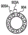
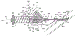
Figures 9A-9B illustrate an embodiment of a longitudinal section of a traceable aortic occlusion catheter, in accordance with the principles of the present invention.
In accordance with the principles of the present invention, FIG. 10A shows a three-dimensional view of a preferred embodiment of a positioner.
Fig. 10B shows a cross-sectional view of a preferred embodiment of a retainer in accordance with the principles of the present invention.
Figure 10C illustrates a longitudinal cross-sectional view of one embodiment of a positioner for a patient, in accordance with the principles of the present invention.
Fig. 10D shows an electrical schematic of one possible embodiment of a detection circuit, in accordance with the principles of the present invention.
Fig. 11A-11E show various aspects of an embodiment of a vessel cannulation device, in accordance with the principles of the present invention.
Fig. 12 illustrates a general view of another embodiment of a vessel cannulation device, in accordance with the principles of the present invention.
Fig. 13 shows a screen view of an embodiment of a vessel cannulation device, in accordance with the principles of the present invention.
Fig. 14A-14C illustrate another embodiment of a vessel cannulation device, in accordance with the principles of the present invention.
FIG. 15 illustrates a cross-section of one embodiment of an expandable sheath, in accordance with the principles of the present invention.
FIG. 16 illustrates a cross-section of another embodiment of an expandable sheath, in accordance with the principles of the present invention.
FIGS. 17A-17D illustrate cross-sections of another embodiment of an expandable sheath, in accordance with the principles of the present invention.
FIG. 17E illustrates a cross-section of a preferred embodiment of an expandable sheath, in accordance with the principles of the present invention.
FIGS. 18A-18C illustrate cross-sections of another embodiment of an expandable sheath, in accordance with the principles of the present invention.
FIGS. 19A-19D illustrate cross-sections of another embodiment of an expandable sheath, in accordance with the principles of the present invention.
FIG. 20 illustrates a cross-section of another embodiment of an expandable sheath, in accordance with the principles of the present invention.
FIGS. 21A-21E illustrate cross-sections of another embodiment of an expandable sheath, in accordance with the principles of the present invention.
FIGS. 22A-22C illustrate three-dimensional views of another embodiment of an expandable sheath, in accordance with the principles of the present invention.
FIG. 23 illustrates a three-dimensional view of another embodiment of an expandable sheath.
FIGS. 24A-24B illustrate three-dimensional views of another embodiment of an expandable sheath, in accordance with the principles of the present invention.
FIGS. 25A-25B illustrate cross-sections and longitudinal sections of another embodiment of an expandable sheath, in accordance with the principles of the present invention.
FIG. 26 illustrates a three-dimensional view of another embodiment of an expandable sheath, in accordance with the principles of the present invention.
FIG. 27 illustrates a three-dimensional view of another embodiment of an expandable sheath, in accordance with the principles of the present invention.
FIG. 28 illustrates a longitudinal section of another embodiment of an expandable sheath, in accordance with the principles of the present invention.
FIG. 29 illustrates a longitudinal section of another embodiment of an expandable sheath, in accordance with the principles of the present invention.
FIGS. 30A-30B illustrate partial and three-dimensional views, respectively, of another embodiment of an expandable sheath.
FIGS. 31A-31B illustrate three-dimensional views of another embodiment of an expandable sheath, in accordance with the principles of the present invention.
FIGS. 32A-32B illustrate an expandable sheath for use in endotracheal intubation, in accordance with the principles of the present invention.
Fig. 33A-33B show side views of embodiments of occlusion catheters.
FIGS. 34A-34B illustrate side views of another embodiment of an occlusion catheter, in accordance with the principles of the present invention.
Fig. 35A-35B show longitudinal sections of an embodiment of a balloon catheter having a base at the tip of the catheter, but most folded over the distal end of the catheter tip, in accordance with the principles of the present invention.
Figures 36A-36C illustrate a longitudinal section of an embodiment of a catheter having a single lumen that may be used for inflation of the balloon and for measuring pressure on the balloon, in accordance with the principles of the present invention.
Fig. 37A-37C show longitudinal and cross-sectional views of another embodiment of an occlusion catheter, in accordance with the principles of the present invention.
Fig. 38A-38C illustrate longitudinal and cross-sectional views of another embodiment of an occlusion catheter, in accordance with the principles of the present invention.
Fig. 39A-39D show longitudinal and cross-sectional views of another embodiment of an occlusion catheter configured at different stages, in accordance with the principles of the present invention.
Fig. 40A-40D show various views of one embodiment of a wheel driven vessel cannulation device in accordance with the principles of the present invention.
Fig. 41 shows a longitudinal section of another embodiment of a vascular intubation device, in accordance with the principles of the present invention.
Fig. 42A-42D illustrate various embodiments of a vessel cannulation device in accordance with the principles of the present invention.
Figures 43A-43D show various possible embodiments of a diaphragm, in accordance with the principles of the present invention.
FIG. 44A illustrates a cross-section of another embodiment of an expandable sheath, in accordance with the principles of the present invention.
FIG. 44B illustrates the proximal end of another embodiment of an expandable sheath, in accordance with the principles of the present invention.
FIG. 44C illustrates the proximal end of another embodiment of an expandable sheath, in accordance with the principles of the present invention.
Fig. 45 shows a diagram of one embodiment of a vessel cannulation device, in accordance with the principles of the present invention.
Fig. 46 shows a diagram of one embodiment of a vessel cannulation device, in accordance with the principles of the present invention.
Fig. 47 illustrates the corresponding time for a vascular cannula device without a fluid channel prefill, in accordance with the principles of the present invention.
Fig. 48 shows the corresponding time without the fluid channel prefilling of the vessel cannulation device, in accordance with the principles of the present invention.
Detailed Description
It is an object of the present invention to produce a system including a method for facilitating semi-automatic or fully automatic access to the arterial system at a puncture site, placement of a sheath within an expandable blood vessel, detection of a catheter tip without the need for fluoroscopy, and, in some embodiments, aortic occlusion. The system is designed for personnel inexperienced with intravascular techniques and enables rapid, safe, and efficient vascular access, such as deployment of an aortic occlusion (EAO) in a vessel for controlling major hemorrhages. Thus, endovascular aortic occlusion can replace emergency department thoracotomy, allowing for non-thoracotomy occlusion for extrathoracic, non-compressive trunk injury.
In certain embodiments, the devices and methods provided by the current invention stop bleeding and stabilize the condition of the injured until final treatment can be performed. Certain inventive elements may also be used alone or in combination with other indications. For example, it is contemplated that the present invention is also suitable for the operation of any endovascular occlusion procedure.
I. System a preferred embodiment of the present invention includes a system having a device, and or system, and associated methods for inserting a guidewire into the vascular system, an expandable sheath, an aortic occlusion catheter, and/or a tip positioning device. In one embodiment, the system includes a cannula device, an expandable sheath, an aortic occlusion catheter, and/or a tip positioning device. The system may be used to insert a guidewire to perform endovascular occlusion and/or to treat hemorrhagic shock.
FIGS. 1A-1C are schematic diagrams of a system. The system includes a vessel cannulation device 10, an expandable sheath 20, an occlusion catheter 30 and a locator 50. More particularly, FIG. 1A shows an apparatus 16 comprising a vascular cannula device 10, the vascular cannula device 10 having a needle 11, the needle 11 being in fluid communication with the device 10, a guidewire 12 disposed within the needle 11, and an expandable sheath 20 disposed over the needle 11. The vessel cannulation device 10 has a lumen 13 through which a guidewire 12 may be passed. Needle 11 has a lumen 14 through which guidewire 12 may be passed. The expandable sheath 20 has a lumen 15 through which the needle 11 and guidewire 12 can be passed. FIG. 1B shows a blocking catheter 30 having a tip 31, a magnet 32 adjacent the tip 31, a shutter plate 33 adjacent the magnet 32, a catheter lumen 34 with a distal opening and at least a proximal port 35 and a port 36, and a monitor 40 optionally connected to the port 36. FIG. 1C shows a fixture 50 with multiple detectors 51.
Typical uses of the present system are shown in fig. 2A-2K. More particularly, fig. 2A shows a vessel cannulation device 10 with a needle 11, a guidewire 12 and a sheath 20, the sheath 20 being positioned adjacent to tissue 100 on a vessel 110. The vessel cannulation device 10 has a lumen 13 (not shown) through which a guidewire 12 may be passed. Needle 11 has a lumen 14 (not shown) through which guidewire 12 may be passed. The expandable sheath 20 has a lumen 15 (not shown) through which the needle 11 and guidewire 12 can be passed. The sheath 20 is positioned over the distal end of the vessel cannulation device 10. The cannula device 10 is moved forward towards the blood vessel 110 so that the needle 11 and the sheath 20 together penetrate the tissue 100, as shown in fig. 2B. With further advancement of the cannula device 10, the needle 11 penetrates the blood vessel 110 (fig. 2C). This triggers a mechanism whereby, within the cannula device 10, the cannula device 10 pushes the guidewire 12 forward through the needle 11 into the blood vessel 110 (fig. 2D). Once the guidewire 12 is advanced into the vessel 110, the guidewire 12 becomes an anchor for the needle 11 such that the needle 11 cannot easily move inwardly or outwardly relative to the vessel and push out of the vessel. The user then manually advances the sheath 20 over the needle 11 and the guidewire 12, both the needle 11 and the guidewire 12 acting as a guide for the sheath 20, and when the cannula device 10 is grasped and the needle 11 is in place together, the sheath 20 passes through the tissue 100 and into the blood vessel 110 until it is well within the blood vessel and cannot be advanced any further (fig. 2E). Alternatively, advancement of the sheath 20 may be performed automatically by the intubation device 10. The cannula device 10, along with the guidewire 12 and needle 11, are then removed from the vessel and tissue, leaving the sheath 20 inside the vessel 110 (fig. 2F).
Once pushed out of the needle and into the vessel lumen, the guidewire straightens the vessel in the direction of the needle and prevents the needle from piercing the vessel. Thus, the guidewire "blunts" the needle. The degree to which a guidewire can perform these functions depends on the characteristics of the vessel, which depend on its material and the particular design (braided, non-braided), as well as the radius, elasticity and stiffness of the guidewire. Blunting may be caused by insertion of a guidewire and or sheath over the needle. Identification of the body lumen may be accomplished by a positive pressure test known as harpoon, or by other methods referred to in the present disclosure, such as a pressure sensor, conductivity sensor, flow sensor, ultrasound sensor, etc. Importantly, the intubation device may provide an indication of vessel insertion by simply pushing the guidewire forward and an additional visual, audible or tactile indication, such as a color change or turning on of an LED, an audible signal or a vibration signal. These signals may be triggered by a microswitch. The microswitch may be operated by virtually any part of the intubation device apparatus. Alternatively, the signals may be triggered by pressure sensors, conductivity sensors, flow sensors, ultrasonic sensors or other known sensors. These sensors may be activated by blood entering the cannula device. In one embodiment, the guidewire may have a diameter of about 0.018 inches and the needle may be an about 18Fr (90mm) needle. Further, the guidewire may be made of stainless steel or nitinol.
After the expandable sheath is positioned within the lumen of the vessel, insertion of occlusion catheter 30 begins as shown in fig. 2G-2K. In particular, fig. 2G shows the sheath 20 positioned within a lumen of a vessel 110, the vessel 110 being connected to an adjacent vessel 120 (e.g., 110 is the femoral artery and 120 is the aorta). Also shown are: occlusion catheter 30 has tip 31, magnet 32, mask 33, and positioner 50 with detector 51. The magnet 32 is disposed in a direction facing the tip 31 or within the tip 31. The shutter plate 33 has a lumen through which the lumen blocking conduit 30 may pass, the lumen being disposed outside the distal facing end of the blocking conduit 30. The positioner 50 has a probe 51, the probe 51 being placed in the general area of the patient's body where the occlusion is to be made, while the occlusion catheter tip 31 is brought into proximity with the sheath 20. Occlusion catheter tip 31 is advanced through sheath 20, sheath 20 expands and allows catheter 30 to enter vessel lumen 110 and advance into adjacent vessel 120 (fig. 2H). As the catheter tip 31 advances under the locators 50, the detector 51 in each locator 50 indicates the sensed condition of the magnet 32 on the catheter tip 31. Fig. 2I shows the indication of the first detector 51 closest to the magnet 32 and since the catheter is advanced intravascularly towards its target (in the case of aortic occlusion for traumatic bleeding, the target is located outside the septum and the superficial anatomical landmark is the xiphoid process), then the detectors 51 indicate that they are approaching the magnet 32 (fig. 2J). The user relies on these indicators to verify the approximate location of the tip and once satisfied with the location of the tip 31, the user can configure the shutter plate 33 (fig. 2K). The physiological parameter may be measured by catheter 30 and a sensor located within catheter or monitor 40. These parameters include, but are not limited to, pressure (venous or arterial, depending on the vessel in which it is inserted), pulse, temperature, blood oxygen saturation, and blood pH. Liquids or drugs may be effected through catheter 30.
It is an object of the present invention to create a method for providing vascular access and/or aortic occlusion (EAO) by using the above system. The method comprises the following steps. As shown in fig. 2A-2K, the user identifies a patient in need of vascular access and/or aortic occlusion. The user selects a puncture point. The user prepares the device 16 after preparation of the puncture site. Device 16 preparation may include opening of a sterile pack, flushing the cannula device 10 with saline, removing the safety needle and possibly the loading of the cannula device 10. The user punctures the skin and tissue 100 of the patient using the needle 11 of the device 16 (fig. 2A-2B). The user advances the device 16 towards the blood vessel. Once puncturing of the vessel lumen 110 is complete, the vessel cannulation device 10 automatically advances the guidewire 12a predetermined distance, typically about 5cm, into the lumen 110 (fig. 2D). Optionally, the vessel cannulation device provides an audible or visual indication of advancement of the guidewire. At this point, optionally, the vessel cannulation device 10 automatically advances the guidewire 12, which guidewire 12 is then manually advanced further into the lumen 110. The guidewire 12 may be marked to provide an indication of the insertion depth. The user now fully grips the vessel cannulation device 10 along with the needle 11 and manually advances the expandable sheath 20 over the needle 11 and the guidewire 12 into the lumen 110 (fig. 2E). The user then holds the expandable sheath 20 in place and retracts and removes the vessel cannulation device 10, needle 11 and guidewire 12 together (fig. 2F). The expandable sheath 20 may now be secured to the patient's tissue 100 using known techniques. This results in the establishment of vascular access. The steps of the method for providing vascular occlusion are as follows: the user places the locator 50 over the area intended for the vessel occlusion. The user inserts the catheter 30 through the sheath 20 into the lumen 110 and typically moves the catheter 30 into the larger blood vessel 120 (fig. 2G-2H). The user continues to advance catheter 30 within vessel 120. Because magnet 32 on catheter tip 31 passes under probe 51 of locator 50, an indication will be given on probe 51 closest to magnet 32 (FIG. 21). As the user continues to advance catheter 30, the indication provided by probe 51 will provide the user with a position of approach to catheter tip 31 (FIG. 2J). When a satisfactory position of tip 31 is reached, the user expands ball 33 and will normally secure catheter 30 in place (fig. 2K). Optionally, the user may now connect the conduit portion 36 to the monitor system 40, and the user measures the pressure distal to the occlusion ball, or uses the port 35 for medication, fluid use, or blood sample draw. Removal of the system is known in the art and includes deflation of ball 33, and retraction of catheter 30.
The following is a more detailed description of each of the above-mentioned system components.
A major problem with vessel cannulation devices vessel cannulation is the unintended penetration of the posterior wall of the vessel. The various embodiments of the vascular intubation devices described herein address this problem by "blunting" the needle. Such "blunting" can be accomplished by the insertion of an object, such as a guidewire through the needle lumen, which reduces the ability of the needle to contact the vessel wall or to puncture and exit; or by advancing the sheath to cover the extent of the needle away from the needle, thereby placing a blunt sheath end at the distal end of the sharpened needle to protect the blood vessel from puncture and to actually "seal" the needle inside.
The vessel cannulation device may include a housing having a distal end with a tip and a proximal end; a guidewire lumen for passing through the housing and at least through the tip; a sensor connected to the guide wire cavity; and an advancement member for advancing at least one of the guidewire or the sheath and operatively connected to the sensor.
In some embodiments, the intubation device of the present invention advances a guidewire in response to a pressure sensor, and the pressure sensor is activated/triggered by fluid within a vessel, such as blood pressure in an artery or vein. The intubation device may automatically advance the guidewire. In another embodiment, the device semi-automatically advances the guidewire.
The intubation device of the present invention utilizes a pressure sensor, such as a diaphragm and/or membrane. When the device is inserted into a blood vessel, the pressure sensor senses the pressure and acts as a guidewire advancing member. In one embodiment, the pressure sensor is a single membrane and may be flexible, such as a diaphragm or a balloon.
The device may also include a fluid channel, which may be pressurized and become part of the pressure circuit. The fluid passage is in communication with the fluid from outside the device such that the fluid flows through the passage to or into a location where contact with the pressure sensor occurs. The pressure circuit may include a fluid passage that provides flow through fluid of the vasculature including arteries and/or veins. The pressure sensor may be disposed on or attached to the fluid channel. In one embodiment, a fluid passage having a pressure sensor at the tip may define a pressure chamber.
It is advantageous to have a minimum internal volume of a liquid channel as the size, shape and configuration of the liquid channel varies. This may help to increase the sensitivity of the device.
The device of the present invention relies on a pressure sensor that is responsive to positive fluid pressure and that is operably connected to the guidewire advancing member. In a preferred embodiment, the pressure sensor is not dependent on the generation of negative pressure within the device. The pressure sensor does not have to use a guidewire advancing member directly. The apparatus of the present invention may advance a guidewire in response to positive fluid pressure detected by the pressure sensor. Thus, the pressure sensor may be a positive pressure detector.
The cannula device of the present invention uses a membrane or membrane that greatly increases the sensitivity of the device and reduces the amount of blood that must flow into the system, thereby reducing response time, especially if the system is prefilled with fluid. In one embodiment, the guide wire is driven forward by a spring drive wheel rather than a piston, which allows the guide wire to be inserted a long distance without having to use a longer device that would be necessary when using a piston to push the guide wire.
The cannula device of the present invention includes a housing having a distal end with a tip and a proximal end; a guidewire lumen for passing through the housing and at least through the tip; a sensor connected to the guide wire cavity; and a guide wire advancing member for advancing the guide wire. The guidewire advancing member is operably coupled to the pressure sensor. The pressure sensor may be connected to a fluid passage, which may be connected to a housing. In one embodiment, the pressure sensor covers an opening at one end of the liquid passage.
A preferred embodiment of the vessel cannulation device is a spring-loaded device that automatically inserts a guidewire into a vessel upon penetration of the needle through the vessel. An embodiment 10 of such an apparatus is shown in fig. 3A-3C. In particular, fig. 3A is a longitudinal section of an embodiment of the vessel cannulation device 10, wherein the vessel cannulation device 10 is in a loaded/armed state, comprising a body 200, the device further comprising a needle 11, the needle 11 having a needle 254, a needle lumen 258 and a needle hub 256, the needle hub 256 being attached to a needle adaptor 257 at a forward end of the needle. The body 200 includes a needle adapter 257, a front lumen 224, a channel 212, the channel 212 ending within the body and leading to a septum interface 261, a rear lumen 226, an air release hole 253, a window 252, an aperture 259 and a shelf 228. Back panel 222 is coupled to a proximal end 260 of body 200. The septum 210 connects the body 200 to the septum interface 261 on the body through a septum adapter 262. The septum 210 is in fluid communication with the adapter 262, the septum interface 261, the channel 212, the needle adapter 257, the needle hub 256, and the needle lumen 258. The lever 214 has two arms and is hinged to a shaft 218. The lever 216 has two arms and is hinged to the shaft 220. One arm of the lever 214 rests on the diaphragm 210 and the other arm rests on the lever 216. The second leg of the control lever 216 protrudes through the trigger aperture 259 into the rear cavity 226 and presses against the slide 202. Holes 255 in the holder 228 are used for possible locations for safety needle insertion. A handle 250 is attached to the slide 202 and protrudes through the window 252. The spring 206 supports the slider 202 at its distal side and the clip 204 at its proximal side. Plate 263 is compressed by proximal clip 204 and distal spring 201. The spring 201 is compressed proximally by the back panel 222. The gasket 208 separates the body 200 into a front cavity 224 and a rear cavity 226. Guidewire 12 flows through the length of vascular access device 10 with its tip located a few millimeters adjacent needle 254 of needle 11, through lumen 258 of needle 11, hub 256, front lumen 224, washer 208, rear lumen 226, slider 202, spring 206, clip 204, plate 263, spring 201, back plate 222, and may protrude from a location adjacent back plate 222 as desired.
In this embodiment, the needle 11 is a standard design needle known to those skilled in the art. The needle adapter between the needle and the body 200 is of standard design and is known to those skilled in the art, for example a "screw-on" design, or a conical pressure-fitting design.
Methods and materials for producing guidewires are known to those skilled in the art. Guidewire 12 may have a soft and/or flexible tip, possibly forming a "J" shaped tip, as is common for normal guidewire use. This flexible tip may prevent the guidewire 12 from damaging the blood vessel as it is advanced by the intubation device.
In one particular embodiment, guidewire 12 may have indicia on its proximal end and protrude from back panel 222 so that the user may have an indication of the length of the guidewire inserted into the vessel.
The clearance between the Outer Diameter (OD) of the guidewire 12 and the Inner Diameter (ID) of the needle 11 must be such as to allow pressure transmission from the needle insertion into the blood vessel. Too small a void will reduce the pressure conduction into the device, thus increasing the device response time. An excessive clearance will have an adverse effect on the response time of the device due to the increased amount of blood that needs to enter the device before the pressure in the device reaches the desired threshold. A preferred clearance for successful testing is the use of a standard 0.018 inch outer diameter guidewire with a standard 18G (0.084mm) inner diameter needle. The optimal choice of needle size for each desired outer diameter of the guidewire can be accomplished by using methods known to those skilled in the art of hydrodynamics.
The large spring 201 extends in a direction toward the end of the back panel 222 and is shown in a compressed state. In a preferred embodiment, the spring 201 is supported by the body 200. This allows the spring to have a larger average diameter ratio of free length, which is then generally unsupported. The spring 201 exerts a compressive force on the clip 204, and the clip 204 presses the small spring 206 forward.
The spring 206 has a maximum spring force that is much less than the spring 201 has in its compressed state, and the spring 206 is in a fully compressed state when the device is in a loaded state, which allows the clip 204 to push against the slider 202. Because clip 204 and slider 202 are both conically shaped, pressing clip 204 against slider 202 compresses the two clip halves together to transmit pressure to guidewire 12. The clip and slider will be described in detail below.
In this embodiment 10 of the device, the septum 210 (e.g., membrane) is in fluid communication with the front lumen 224 via the channel 212. Importantly, all internal passages, lumens and chambers within the fluid pathway, including needle lumen 258, hub 256, forward lumen 224, passageway 212, septum connector 262 and septum 210, must have a minimum possible volume. This full internal volume is a major factor affecting the device response time, from the time of vessel penetration to the time of automatic advancement of the guidewire 12.
Fig. 43A-43D show different exemplary possible embodiments of the diaphragm 212. In particular, FIG. 43A is a cross-section of one embodiment of a diaphragm 270a, including a bottom housing 272a, a top housing 278, a membrane 273A, an inlet 271a, an outlet 275, and a piston 274. The membrane 273a is pressed between the top housing 278 and the bottom housing 272a at its edges and creates a sealed chamber 274 a. Inlet 271a is in fluid communication with chamber 274 a. The piston 274 is connected to the middle of the membrane 273 a. These films are known in the art. Liquid entering inlet 271a increases the pressure in chamber 274a, thereby causing the film 273a to expand and protrude outwardly and thereby push against piston 274.
FIG. 43B is a cross section of diaphragm embodiment 270B, including bottom housing 272B, diaphragm 273B, and having activation region 276, inlet 271B. The membrane 273b is attached to the bottom housing 272b around its perimeter to create a sealed chamber 274 b. Inlet 271b is in fluid communication with chamber 274 b. The activation region 276 is the location where the membrane 273b is most likely to deform. Such membranes are known in the art. Liquid entering inlet 271b increases the pressure in chamber 274b, thereby causing the film 273b and actuating region 276 to expand and protrude outwardly.
FIG. 43C is a cross section of a diaphragm embodiment 270C, including a bottom housing 272C, a balloon 273C, and having an activation plate 277a, the activation plate 277a hinged to the bottom housing 272C on an axis 279a, and an inlet 271C. Balloon 273c has a lumen 274c, lumen 274c being in fluid communication with inlet 271 c. Fluid inlet 271c increases the pressure within chamber 274c of balloon 273c, thereby causing balloon 273c to extend and protrude outwardly and causing actuation plate 277a to rotate about axis 279 a.
One embodiment of a vessel cannulation device 269 utilizing a septum 270c is shown in figure 41. All aspects of device 269 (except for the replacement of diaphragm 210 with diaphragm 270 c) are the same as those of device 10. The use of the septum 270c may allow the device 269 to have a smaller size than the device 10.
FIG. 43D is a cross section of diaphragm embodiment 270D, including bottom housing 272D, diaphragm 273D hinged with bottom housing 272D on shaft 279b, and inlet 271D. The diaphragm 273d is pressed around it between the housing 272d and the clamp 280 and creates a sealed chamber 274 d. Chamber 274d is in fluid communication with inlet 271 d. The liquid inlet 271d increases the pressure within the chamber 274d, thereby causing the film 273d to extend and protrude outwardly and causing the actuation plate 277b to rotate about the shaft 279 b.
Typically, embodiments 270a and 270b of septum 210 may have a generally circular shape, while embodiments 270c and 270d may have other shapes, such as rectangular or other shapes, which may help minimize the size of device 10.
Returning to FIG. 3A, the diaphragm 210 has a chamber of minimal volume on the side connected to the channel 212. In a preferred embodiment, the septum will have a diameter of about 25mm and will generate a total force of about 3.5N when inserted into a blood vessel having an internal pressure of 40mm Hg. In this embodiment, the diaphragm is pre-calibrated to catch the lever device when a pressure of 40mm Hg or more is transmitted to the diaphragm.
Typically, the septum 210 will have a diameter of between 5mm and 100mm and will produce a total force of between 0.1N and 60N when inserted into a blood vessel having an internal pressure of 40mm Hg.
Preferably, the septum 210 will have a diameter between 10mm and 60mm and will produce a total force of between 0.5N and 20N when inserted into a blood vessel having an internal pressure of 40mm Hg.
In a different embodiment, the membrane pressure threshold may be manually calibrated by adjusting the length of the compression spring, which generates a force on the membrane, by a set screw or similar device. Methods of constructing films are known to those skilled in the art.
In a different embodiment, the diaphragm pressure threshold may be manually calibrated by adjusting the length of the compression spring by a set screw or similar device, wherein the compression spring exerts a force on one or both of the lever 216 and the lever 214.
The sensor may be a membrane. In one embodiment, the membrane may be comprised of a thin film. Films suitable for use with the apparatus of the present invention include those made of, for example, silicon, oxides, nitrides, glasses, polymers and metals. The thickness of the film may vary, but ranges from 10 to 500 μm, such as a thickness from 10 to 20 μm, 20 to 50 μm, 50 to 100 μm, 100 to 200 μm, 200 to 500 μm. In some embodiments, the lateral dimension of the film may be about 10 mm. The film may be elastic and easily stretchable. The membrane may be round, square or pillow-shaped. The membrane may be made of a plastics material and may be responsive to deflection by pressure.
For example, the membrane may deflect and thereby actuate a guidewire advancing member in response to blood pressure of about 20mm Hg or more. Such a membrane is particularly useful for inserting a guidewire into an artery. Alternatively, the membrane may deflect and thereby actuate a guidewire advancing member in response to blood pressure of about 5 to 20mm Hg. Such a membrane is particularly useful for insertion of a guidewire into a vein.
The surface area and/or volume of the film may be varied as desired for use. For example, the surface area of the film may be from 20mm2To 8000mm2. In addition toIn one embodiment, the surface area may be from 100mm2To 500mm2. In other embodiments, the membrane is configured to be a guidewire advancing member when the membrane is inflated to a volume of from about 0.02cc to about 8cc, or from about 0.05cc to about 2 cc.
The diaphragm may also be a balloon. In one embodiment, the septum is comprised of a flexible membrane and has a fluid-filled lumen.
When using the device of the present invention, the membrane (diaphragm) deflects in response to pressure. For example, when blood rushes into the device, the membrane (septum) expands from its resting position and thus flexes outward. As the membranes expand (e.g., bow outward), they actuate a guidewire advancing member (as shown) for advancing the guidewire. After expansion, the membrane can return to its rest position due to its elasticity. Thus, the cannula device of the present invention may rely on a positive pressure generated by a liquid, such as blood, to expand, such as deflect, an elastic membrane from its resting position.
The length of time between puncturing the vessel and advancing the guidewire is the response time. In particular, the response time may be defined as the time period between puncturing the blood vessel and stopping forward movement of the guidewire advancing member. The response time is measured when the pressure chamber and/or membrane is not pre-filled with a biologically acceptable liquid. The use of a flexible membrane (e.g., septum) may allow the intubation device to have a fast response time. Thus, the device of the present invention may provide rapid vascular access after puncturing the blood vessel. The response time may range, for example, from about 0.02 seconds to about 1 second, or from about 0.05 seconds to about 0.5 seconds. In some embodiments, the response time may be between 300ms and 400ms for devices without a pre-fill channel. Alternatively, for devices without pre-fill channels, the response time may be about less than 200 ms.
In one embodiment of the invention, the pressure chamber (e.g., a fluid channel leading to the pressure sensor) and/or the membrane (e.g., a balloon) may be pre-filled with a biologically acceptable fluid, such as saline. For example, the pressure chamber and/or the membrane (e.g., balloon) may be at least partially pre-filled. In such an embodiment, the response time of this device may be less than the response time of a device that is not pre-filled. For example, the response time of a cannula device with a prefilled fluid channel is approximately twice as fast as the response time of a fluid channel without a prefilled device of the same device.
In a different embodiment, the pressure on the lever arrangement may be set to a range having a maximum and a minimum value. As schematically shown in fig. 3D-3E, the cut-off value for the minimum pressure can be set by installing a pilot valve.
In particular, FIG. 3D is a cross-sectional schematic view of a pilot valve assembly 290A, according to one embodiment of the invention. The pilot valve assembly 290A includes a housing 298 having an inlet 291, passage 293, outlet 294, diaphragm 292, piston 299, valve 295, wherein valve 295 has aperture 289, resilient member 296, and adjustment screw 297. As shown in fig. 3D, from bottom to top, the lower surface of the diaphragm 292 is in fluid communication with the inlet 291, the upper surface of the diaphragm 292 is in contact with the piston 299, and the piston 299 is in contact with the valve 295. The valve 295 is in turn in contact with the resilient member 296. The resilient member 296 may be adjusted by an adjustment screw 297. Fig. 3D shows the pilot valve at a first critical pressure level. At this pressure level, the force generated on the spring 296 is greater than or equal to the force generated on the diaphragm 292, which causes the aperture 289 of the valve 295 to allow free flow of liquid from the inlet 291 through the passage 293 to the outlet 294. Tightening the adjustment screw 297 will compress the spring 296, thereby increasing the force on the valve 295 and increasing the upper pressure limit.
Fig. 3E is a cross-sectional schematic view of a pilot valve device 290B. The pilot valve assembly 290B includes a housing 298 having an inlet 291, passage 293, outlet 294, diaphragm 292, piston 299, valve 295, wherein valve 295 has aperture 289, resilient member 296, and adjustment screw 297. From below, the lower surface of the diaphragm 292 is in fluid communication with the inlet 291, the upper surface of the diaphragm 292 is in contact with the piston 299, and the piston 299 is in contact with the valve 295. The valve 295 is in turn in contact with the resilient member 296. The resilient member may be adjusted by an adjustment screw 297. Fig. 3E shows the pilot valve at or above a critical pressure level, where the force generated on the spring 296 is less than the force generated by the pressure of the liquid on the diaphragm 292, which causes upward movement of the valve 295 and locks the flow of liquid from the inlet 291 through the passage 293 to the outlet 294.
Pressure: typically, in shock conditions, arterial blood pressure can drop to an average of about 50mm Hg, and diastolic pressures can be even lower, perhaps as low as 30mm Hg, but almost no lower than 20mm Hg, where the patient is still salvageable.
In a preferred embodiment, the diaphragm 210 and the chamber of the channel 212 will be filled with a biologically acceptable liquid or gel. A biologically acceptable liquid or gel may reduce the septum response time for the needle to penetrate the blood vessel.
In a preferred embodiment, the spring 201 may be composed of piano wire having a spring rate of 0.3N/mm, a wire diameter of about 0.8mm, an average diameter of about 0.9mm, 17 effective coils, and a net length of about 90 mm. In the compressed state of the spring, it will have a deflection length of 30mm and generate a force of about 20N.
Typically, the uncompressed length of the spring 201 may range between about 50mm and 200mm, and preferably may range between about 80mm and 150 mm. The average diameter of the spring 201 may range between about 2mm and 30mm, and preferably may range between about 5mm and 15 mm. The wire diameter of the spring 201 may range between about 0.3mm and 2mm, and preferably may range between about 0.5mm and 1.2 mm. The spring rate of spring 201 may range between about 0.05N/mm and 2N/mm, and preferably may range between about 0.15N/mm and 1N/mm.
Alternatively, the spring 201 may be comprised of a plurality of compound springs, the use of which is known to those skilled in the art.
In a preferred embodiment, the spring 206 may be composed of piano wire having a spring rate of 0.6N/mm, a wire diameter of about 0.5mm, an average diameter of about 5mm, 8 effective coils, and a net length of about 8 mm. In the compressed state of the spring, it will have a deflection length of 6mm and generate a force of about 1.3N.
The lever 214 pivots about a hinge 218 attached to a bracket 228 and extends outwardly from the body 200. The trigger 216 also rotates about the hinge 220 on the bracket 228.
As shown in fig. 3, when the device is in a "loaded" state, the wire 212 is positioned through the center of the back plate 222, the spring 201, the clip 204, the spring 206, the slider 202, and the washer 208, with the tip of the wire 212 only a few millimeters from the tip of the needle 11. The slider 202 is configured such that the trigger 216 can prevent it from moving forward while the large spring 201, the clip 204 and the small spring 206 exert forces on it in an attempt to push it forward. Since the force on the large spring 201 is much greater than the force on the small spring 206 at this location, the clip 204 is pressed into the conical cavity of the slider 202 and its longitudinal split 230 is compressed so that its two halves compress the guidewire 12 and prevent its movement relative to the vessel cannulation device 10.
Each of the trigger 216 and the lever 214 has two arms. The slide 202 presses one arm of the trigger 216, the other arm of the trigger locking one arm of the lever 214. The other arm of the lever 214 presses against the diaphragm 210.
Figure 4 shows the clip 204 in detail. The clip 204 may be a conical member with a longitudinal split 230 dividing it into two halves 234, and a longitudinal slot 232, the diameter of the longitudinal slot 232 being smaller than the diameter of the guidewire 12 to form a tight fit.
Fig. 5A and 5B show the slider 202 in detail. Fig. 5A is a three-dimensional view of a slide 202. the slide 202 is a cylindrical member with a conical cavity 240, a cylindrical cavity 242 and a tunnel 244, the diameter of the tunnel 244 being slightly larger than the diameter of the guidewire 12. A conical cavity 240 and a cylindrical cavity 244 connect the cylindrical cavity 242. The conical cavity 240 faces the proximal end of the cannula device 10. A guidewire may be passed through the tunnel 244, cylindrical cavity 242 and conical cavity 240 to pass through the slide 202. In addition, the slider 202 may have a circumferential groove 246 around its circumference. Fig. 5B is a longitudinal section of the part.
As shown in fig. 3B-3C, in use, when the needle 11 in the vascular cannula device 10 penetrates a blood vessel or other lumen containing a pressurized fluid, pressure is transmitted into the needle 11 and the cylindrical front portion 224 and into the channel 212, which the channel 212 guides into the septum 210. As a result of this positive pressure, the diaphragm 210 is rotated. Movement of the diaphragm 210 causes rotation of the lever 214 such that it no longer locks the trigger 216 in place and, in turn, allows the slider to move forward within the body 200. As the slide 202 and clip 204 move forward, the guidewire 12 is advanced into the vessel. At the end of its travel, the large spring 201 experiences less force than the small spring 206, so that the clip 204 is no longer compressed by the conical cavity 240 in the slider 202 and its two halves do not compress against each other, thus releasing the guidewire 12 and allowing it to pass freely through all components of the vessel cannulation device 10.
The gasket 208 and diaphragm 210 may be well manufactured by one of ordinary skill in view of suitable medical grade materials. The diaphragm may preferably be made of a material that expands in response to the pressure generated by the blood. In one embodiment, the diaphragm is made of a material that can deflect in response to pressure generated by blood.
In one embodiment of the intubation device, a handle 250 is attached to the slide 202. A longitudinal window 252 is added to the body 200 to allow arming of the cannula device by pulling back the handle 250 towards the proximal end of the cannula device, thus compressing the spring 201 and placing the slider 202 in a position where it can be locked by the control rod 216. In a different embodiment, the handle 250 may be of a removable design that does not partially protrude through the window 252 after it has been separated. In another embodiment of intubation device 10a, as shown in FIG. 3F, a spring 251 is added. Of course, the spring 201 and the spring 206 are sized such that when the slider 202 is released by the lever 216, the slider 202 pushes against the spring 251, the force generated by the spring 201 is greater than the force generated by the spring 206, and thus the guide wire does not automatically release. The guidewire can then be manually released by pushing the handle 250 towards the distal end of the device, thus compressing the spring 251 and increasing the length of the spring 201 to that point produces less force than the spring 206. The clip will then be pushed towards the proximal end of the device and the guidewire released.
As shown in fig. 3A-3C, in a preferred embodiment, the hole or opening 253 or plurality thereof will vent air out of the body 200 to prevent a dampening effect caused by compressed air flowing through the slider 202 toward the gasket 208.
In a preferred embodiment of the cannula device, a safety needle 254 is placed in any of the openings 255 to occupy the site until the device is ready for use. The safety needle will prevent accidental actuation of the device, which would normally occur if it were dropped, or other nuisance handling. The safety needle acts as a mechanical barrier preventing operation of the lever arrangement.
In one embodiment, the expandable sheath may have a means for attaching it to the distal end of the needle hub. In another embodiment, the expandable sheath may have a means for attaching it to the distal end of the intubation device.
Another preferred embodiment of an intubation device 331 is shown in fig. 40A-40D. This embodiment uses a turret as the propulsion means. The use of a wheel is advantageous because it allows the intubation device to have a length that is independent of the desired depth of guidewire insertion. In particular, as shown in fig. 40A-40D, the cannula device 331 includes the following components: the device body 332 having a port 333; needle hub adapter 334 having a through opening 340; and one or more radial openings 341 to connect the openings 340 with a tube 338. The cannula device 331 also includes a gasket 208 for separating the device 331 into a forward region 350 and a rearward region 351. Needle 11 is connected to the tip of needle hub adapter 334 and guidewire 12 is inserted into port 333.
The device 333 also includes a diaphragm assembly 343, the diaphragm assembly 343 including a top diaphragm housing 336, a diaphragm 335, a piston 339, and a bottom diaphragm housing 337, the bottom diaphragm housing 337 having a vent 356. Top septum 336 has an opening 344, opening 344 being connected to hub adapter 334 by tube 338.
The apparatus 333 also comprises a propulsion device 345, the propulsion device 345 comprising the following components: hub 346, coil spring drive motor 348, drive shaft 349, freewheeling shaft 352 and wheel 353. The axles are spaced a distance between the circumference of the wheel 353 to create a tight fit, the wheel 353 creates a surface that contacts the guidewire 12 and creates sufficient friction to drive the guidewire 12. One of the factors that determine friction and drive wire 12 is the coefficient of friction between wire 12 and wheel 353.
In one embodiment of this apparatus 331, the guidewire 12 is pre-treated with a surface coating to create a high coefficient of friction, thereby reducing the tight fit required for the wheel 353 and reducing the torque required to be provided by the drive motor. In another embodiment, one or more secondary drive wheels replace the freewheel. The additional torque provided by the one or more drive wheels may allow for a greater interference fit between the wheels 353. The number of driving second wheels may vary. In yet another embodiment of the device 331, there are 2 or more sets of drive wheels. Having multiple drive motors may allow more force to be transmitted into the guidewire or achieve a smaller tight fit between the wheels 353 with the same force, thus requiring less torque from the drive motor 348.
In a different embodiment of a device 354, a sensor 355 is located proximate to needle hub adapter 334, as shown in FIG. 40D. As is known in the art, the drive motor assembly 357 includes an electric motor, batteries and control circuitry. When the sensor 355 sends a signal to the motor control circuit, the motor control circuit energizes the motor 357 and the motor 357 pushes against the guidewire 12. Sensor 355 may be a pressure sensor, a photoelectric sensor, a resistive sensor, or an ultrasonic sensor as known in the art.
In particular, FIG. 40D is a longitudinal section of the device 354. This embodiment includes: the device body 332 having a port 333; needle hub adapter 334 having a through opening 340; and one or more radial openings 341 to connect to the opening 340 with the sensor 355. The device 354 also includes a gasket 208 for separating the device 354 into a front region 350 and a rear region 351. Needle 11 is connected to the tip of needle hub adapter 334 and guidewire 12 is inserted into port 333.
The apparatus 354 also includes a propulsion device 359, the propulsion device 359 including the following components: hub 346, electric drive motor 357, drive shaft 349, freewheeling shaft 352 and wheel 353. The axles are spaced a distance between the circumference of the wheel 353 to create a tight fit, the wheel 353 creates a surface that contacts the guidewire 12 and creates sufficient friction to drive the guidewire 12.
As shown in fig. 42A-42B, an embodiment of a vessel cannulation device 2500 uses similar means to those previously described for vessel cannulation devices 10 for automated advancement of a sheath over a needle into a vessel. The device 2500 automatically advances a sheath a large distance over the needle and inserts the sheath into the blood vessel.
In embodiment 2500, typically sheath 2512 can be advanced automatically about 20mm to 100mm, preferably about 30mm to 60 mm.
In particular, figure 42A is a longitudinal section of an embodiment of a vessel cannulation device 2500 in its loaded/assembled state, comprising a body 200 with a needle 11, the needle 11 having a needle 254, a needle lumen 258 and a needle hub 256, the needle hub 256 attached to the forward end of a needle adapter 257. The body 200 includes a needle adapter 257, a front lumen 224, a channel 212, the channel 212 ending within the body and leading to a septum interface 261, a rear lumen 226, an air release hole 253, a window 252, an aperture 259 and a shelf 228. Back panel 222 is coupled to a proximal end 260 of body 200. The septum 210 connects the body 200 to the septum interface 261 on the body through a septum adapter 262. The septum 210 is in fluid communication with the adapter 262, the body-to-septum interface 261, the channel 212, the needle adapter 257, the needle hub 256, and the needle lumen 258. The lever 214 has two arms and is hinged to a shaft 218. The lever 216 has two arms and is hinged to the shaft 220. One arm of the lever 214 rests on the diaphragm 210 and the other arm rests on the lever 216. The second leg of the control lever 216 protrudes through the trigger aperture 259 into the rear cavity 226 and presses against the slide 202. Holes 255 in the holder 228 are used for possible locations for safety needle insertion. The spring 206 supports the slider 202 at its distal side and the clip 204 at its proximal side. Plate 263 is compressed by proximal clip 204 and distal spring 201. The spring 201 is compressed proximally by the back panel 222. The gasket 208 separates the body 200 into a front cavity 224 and a rear cavity 226. Guidewire 12 flows through the length of vascular access device 10 with its tip located a few millimeters adjacent needle 254 of needle 11, through lumen 258 of needle 11, hub 256, front lumen 224, washer 208, rear lumen 226, slider 202, spring 206, clip 204, plate 263, spring 201, back plate 222, and may protrude from a location adjacent back plate 222 as desired.
In addition, vessel cannulation device 2500 includes a bridge 2502, bridge 2502 including a proximal end 2504, a tag 2506, a distal end 2508 and a loop 2510. Tag 2506 is attached to slider 202 with ring 2510 around the proximal end of needle 11 and the distal end of hub 256. The device 2500 further includes a sheath 2512, the sheath 2512 including a hub 2514, a shaft 2516, a tip 2518, and a lumen 2519. Sheath 2512 is placed over needle 11 to facilitate passage of needle 11 through hub 2514 and lumen 2519, with hub 2514 at the proximal and distal ends of ring 2510.
As shown in FIG. 42B, upon release of the vessel puncture and control rod 216, the slider 202 is pushed forward and the bridge 2500 is moved forward therewith. As it is advanced relative to the needle 11, the ring 2510 pushes the hub 2514 of the sheath 2512 forward over the needle 11 so that the tip 2518 is pushed into the vessel a distance approximately similar to that of a guidewire delivery.
Alternatively, as shown in fig. 42C-42D, an embodiment of a vessel cannulation device 2520 utilizes similar means as the vessel cannulation device 2500 previously described to facilitate automated advancement of a sheath over a needle and into a vessel. Device 2520 automatically advances the sheath a short distance over the needle to adequately cover the needle, thereby "blunting" the needle and allowing the user to further manually insert device 2500 without risk of puncturing the posterior wall of the blood vessel.
Fig. 42C is a longitudinal section of the apparatus 2500. The components of all devices 2520 are identical to the components of device 2500 described above, except for bridge 2502. Further, the vessel cannulation device 2520 includes a bridge 2522, the bridge 2522 including a proximal end 2524, a tag 2526, a distal end 2528 and a loop 2530. A spring 2540 is located at the proximal end of the washer 208. The tag 2526 is located at the proximal end of the spring 2540, and the ring 2530 surrounds the proximal end of the needle 11 and the distal end of the hub 256. Device 2520 further includes a sheath 2512, sheath 2512 including a hub 2514, a shaft 2516, a tip 2518, and a lumen 2519. Sheath 2512 is placed over needle 11 to facilitate passage of needle 11 through hub 2514 and lumen 2519, with hub 2514 at the proximal and distal ends of ring 2510.
As shown in fig. 42D, upon vessel penetration and release of the control rod 216, the clip 204 and slider 202 are advanced forward and move the guidewire 12 into the vessel 11. The slider 202 enters the rear cavity 226 until it encounters the label 2526. The slider 202 then continues to advance while pushing the label 2526 and the bridge 2522. As the bridge 2522 is advanced relative to the needle 11, the ring 2530 pushes the hub 2514 of the sheath 2512 forward and over the needle 11 so that the tip 2518 is pushed into the blood vessel a distance sufficient to cover the needle 254 of the needle 11, which is less than the distance the guidewire 12 has moved forward. Typically, in embodiment 2520, sheath 2512 will advance automatically by about 1mm to 20mm, preferably by about 3mm to 10 mm.
Insertion of sheath 2512 in embodiment 2520 will lag insertion of guidewire 12. This occurs because the tab 2526 is spaced a distance from the slider 202, and the slider 202 must slide this distance before pushing the tab 2526 forward to insert the sheath 2512 into the blood vessel. This is advantageous because a better anchor is obtained when the sheath is advanced, thus preventing loss of lumen access, and insertion of the sheath faces high electrical resistance from the tissue.
The sheath used in embodiments 2500 and 2520 can be a conventional non-expandable vascular cannula as known in the art, or an expandable sheath of the present invention.
The intubation device may be inserted into the sheath 2512 and the guidewire 12 simultaneously. Alternatively, insertion of the sheath 2512 may only be accomplished with a vessel cannulation device if, for example, a guidewire is not used.
Insertion of the guide wire into the body requires that the guide wire be maintained sterile. To facilitate maintaining sterility of the guidewire in non-sterile environments, a cap or housing may be used. The guide wire protrudes from the proximal end of the intubation device, where it will be covered by the housing to maintain its sterility. The guidewire may be stored in a crimped state or in a free state.
Expandable sheath sheaths are typically used to remove devices that expand after insertion rather than inserting devices that are larger than the original sheath diameter. In contrast, an expandable sheath produced in accordance with the present invention has the advantage of expanding more in the proximal to distal direction than in the distal to proximal direction.
A preferred embodiment of an expandable sheath 20 is shown in fig. 6-8. In particular, fig. 6 is a three-dimensional view of an embodiment of an expandable sheath 20 including a sheath hub 304 from which a longitudinally extending sheath shaft 300 has a tip 302 at its distal end. The tip 302 may be tapered. The expandable sheath 20 has a lumen 301, and the lumen 301 may have a needle or guidewire therethrough. The sheathing bar 300 comprises longitudinal beams 303 and bars 305. The hub 304 may have a liquid outlet 306. The fluid outlet is connected to the interior cavity of the hub 304. The sheath 20 is typically inserted into the blood vessel over the needle such that the needle hub 312 is proximal to the sheath hub 304 and the needle 310 is distal to the sheath tip 302. Fig. 7 is a longitudinal section showing the same components except for the hemostatic valve 308. The hemostasis valve 308 is positioned within the hub 304, spanning the lumen 313 of the hub 304. A hemostasis valve 308 may be located proximate the liquid outlet 306. The hemostatic valve 308 may be removed to facilitate insertion of larger diameter instruments.
The position 320 of the cross-section shown in the figures is also shown in fig. 8A-B, fig. 15-21, fig. 25B and fig. 30A.
The shield tip 302 has an inner diameter with a close tolerance fit corresponding to the outer diameter of the needle 11. The inner diameter of the sheath rod 300 also has a close tolerance fit along most of its length corresponding to the outer diameter of the needle 11. Because sheath rod 300 is proximate to sheath hub 304, the inner diameter of sheath rod 300 may expand to the inner diameter of sheath hub 304. The inner diameter of the sheath hub 304 is larger than the outer diameter of the needle 11, such as by 50%, preferably 300%, and possibly 500% or more. For example, an 18 gauge needle, having an outer diameter of about 1.3mm, may be used with an expandable sheath 20, the expandable sheath 20 having a sheath hub 304, the sheath hub 304 having an inner diameter of about 14Fr, corresponding to about 4.6mm, i.e., 250% larger than the needle. Thus, shield rod 300 can expand circumferentially at least a distance between the outer diameter of needle 11 and the inner diameter of shield hub 304, although it can even expand its diameter beyond the inner diameter of the hub.
The sheath tip 302 may be conical so that at its end, the outer diameter of the sheath tip 302 may become more closely or exactly equal to the outer diameter of the needle 310.
In addition, the needle 11 may have a cap and "flashing" chamber at its hub 312 to allow proper identification when the needle enters a blood vessel without exposing the blood vessel to outside air. The needle may pierce tissue and/or a blood vessel (such as an artery wall).
Fig. 8A-8B are cross-sectional views of the shaft 300 with the expandable sheath 20 in position 320. In the preferred embodiment, the sheath is composed of a single polymeric material, such as High Density Polyethylene (HDPE). As shown in fig. 8A, the shield wall includes one or more beams 303, the beams 303 being connected by one or more bars 305. The cross-beam 303 and the bar 305 are longitudinally extended along the sheathing bar 300. The cross beam 303 has a region of greater wall thickness than the beam 300 which gives the beam 300 longitudinal stiffness and column strength, while the strip has a region of lesser wall thickness where the material of the beam 300 can easily extend radially. This can occur in the case of using non-elastic materials, such as high density polyethylene in this example, in the manner of plastic deformation; or may occur in the case of an elastic material, such as silicone, in an elastically deformable manner. Figure 8B is a cross-sectional view of the rod 300 at position 320 showing the rod 300 in its expanded state with the beam 303, the stretched strip 307 and the instrument 330, the instrument 330 being located inside the rod 300.
In use of the system of the invention, the sheath 20 is inserted into the blood vessel together with the needle 11, the needle 11 being attached to the blood vessel insertion device 10. The sheath 20 is positioned over the needle 11 to facilitate passage of the needle 11 through the lumen 301 of the sheath 20. The sheath 20 is optionally attached to the device 10 or the needle hub 312. This may be accomplished by using a plug fitting, tapered press fit, screw fitting, or other attachment methods known in the art. Preferably, these connections are sufficient to prevent the sheath 20 from unintentionally passing beyond the needle 11 and not requiring a great deal of force to break it. The vessel puncture in this case may be accomplished by insertion of the guidewire 12 and an indicator, or by blood flow through the needle or blood in a chamber where a "flash" is seen at the needle hub when the vascular insertion device 10 is not in use. These methods of making a flash chamber are known to those having skill in the art. With the vessel puncture, the sheath 20 is slid into the vessel and the needle 11 is removed. The cross-piece 303 prevents expansion of the sheath 300 during device insertion, which may occur due to friction between it and the skin, subcutaneous tissue and vessel wall.
The outer diameter of the intravascular device 330 is between the outer diameter of the needle 11 and the inner diameter of the sheath hub 304, and the device 330 can then be introduced into the sheath 20. As the instrument 330 is advanced through the sheath 20, it uses radiation force on the shaft 300 and the strip 305 extends until the inner diameter of the shaft 300 receives the instrument (see fig. 8B) and allows it to enter the vessel.
The expandable sheath or portions thereof may be made using one or more materials. Typically, the material forming the sheath comprises a medical grade synthetic material or plastic. Typical materials may include, but are not limited to, soft polyvinyl chloride, polyurethane, silicone, Linear Low Density Polyethylene (LLDPE), polyethylene, high density polyethylene, (DHPE), polyethylene-lined ethyl vinyl acetate (PE-EVA), polypropylene, latex, thermoplastic rubber, Polytetrafluoroethylene (PTFE), expanded polytetrafluoroethylene (ePTEE), fluoroethylene propylene (FEP), Perfluoroalkoxy (PFA), ethylene-tetrafluoroethylene copolymer (ETFE), ethylene-chlorotrifluoroethylene (ECTFE), Polychlorotrifluoroethylene (PCTFE), Polyimide (PI), Polyetherimide (PEI), Polyetherketone (PEEK), polyamide-imide (PAI), other fluoropolymers, and the like.
Occlusion catheter the occlusion catheter of the preferred embodiment of the system described previously is an arterial balloon catheter with a double lumen and a magnet at the tip. An example of such a catheter is shown in fig. 9. In particular, fig. 9A shows an occlusion catheter 400 having a working lumen 402, a balloon inflation lumen 404, and a balloon 406. Working lumen 402 extends through catheter 400 and terminates in occlusion catheter tip 410. The balloon 406 is disposed facing the distal end of the occlusion catheter, near the tip 410. Working lumen 402 may be used for intravascular blood pressure measurements, use of drugs and fluids, and sampling blood in the vicinity of the balloon. The catheter 400 also has a balloon inflation lumen opening 412, which is located within the balloon 406; and a magnet 408 adjacent to the balloon 406.
Fig. 9B shows the typical direction of the magnetic field lines 420 that are induced in the magnetic field by the magnet 408 located at the tip 410 of the occlusion catheter 400. In one embodiment, the magnets used are small capacity rare earth magnets, preferably composed of neodymium. The magnetic field generated by the magnet has a preferred volume of 0.5mm3And 30mm3This is sufficient to be detected by the locator device of the invention. The strength of the magnetic surface electric field emitted from the magnet is typically about 5000-.
In use, the user first detects the surface condition of the patient and decides where to place the balloon 406 based on anatomical landmarks, for example under the xiphoid process. The user then places a locator 50 (described in detail later) within that area of the patient. Occlusion catheter 400 is inserted into the vessel, such as over a femoral artery, through sheath 20 or other known vascular access device. The working chamber 402 can be used immediately for central arterial blood pressure measurement, blood sampling, and fluid, blood or drug use. If stable vessel occlusion is desired for the patient, the catheter 400 is advanced to a desired depth, which can be predicted for each different patient, for example, by measuring the straight line distance from the puncture site to the xiphoid process and increasing by 20%, which is only a rudimentary estimate of the actual distance of the intracorporeal catheter through the vasculature. Because the magnet 408 of the tip 410 passes through the detection zone of the detector 51 on the fixture 50, the detector indicates the approximate position of the magnet, and the user can infer its approximate position. For aortic occlusion in hemorrhagic shock, it is important to ensure that catheter tip 410 is not unintentionally advanced into the lateral groin or femoral artery, or into the renal artery. These possibilities are excluded by the indication of the detector 51 on the centerline of the patient's body. It is also important to ensure that the balloon 406 is above the patient's diaphragm (between the abdomen and thorax) and does not enter the aorta too deeply, which could cause unnecessary and undesirable deadly occlusion of the arterial branches. The indicator of the detector 51, approximately at the level of the xiphoid process, confirms the correct position of the balloon 406.
V. locator the locator device of the preferred embodiment of the system described above includes a series of probes mounted on a flexible pad or cloth. The locator may be disposable so that bacterial issues are not a concern in its use. Typically, the positioner 50 will be positioned over the patient's upper abdomen and lower chest, in the center of the xiphoid process, as shown in fig. 10A. In particular, FIG. 10A is a three-dimensional view of the positioner 50 on a patient's torso. The fixture 50 includes a pad 500 and one or more detectors 51. The mat 500 or a portion thereof may be resilient. The cushion 500 is configured to fit the patient's body so that it remains stable on the patient's body. The one or more detectors 51 may be used in the form of a detector array, which may be defined as rows and columns, e.g., the distribution of the one or more detectors 51 may be defined as rows 520 and columns 522. A detector 51 having an array of 5 rows by 5 columns is shown. The size of the array may vary. In one embodiment, the array has a size range of 3 to 8 rows by 3 to 8 columns. The distance between rows 520 and columns 522 may be different. The distribution of one or more detectors 51 may be left unfilled. For example, the distribution may be (a) around the center of the positioner, (b) diagonal, (c) or hexagonal. The mat 500 may have a power source 510 or the power source may be separate therefrom. The power source 510 may be a battery, such as a 1.5 volt battery.
Fig. 10B is a sectional view of the retainer 50. The mat 500 is shown in cross-section and has an array of detection circuits 501, each detection circuit being connected to an LED508, the LEDs 508 extending above the mat 500. The power supply 510 is located on one side of the mat 500. Each detection circuit 501 may detect the magnetic field of a magnet, such as magnet 408, when it is within a certain full detection zone 530. Upon detecting the presence of a magnetic field within the full detection region 530, the LED508 will illuminate and indicate its presence. It is possible for more than one full detection region 530 to overlap to produce an overlapping detection region 532, while the remainder of the full detection region 530 is for a non-overlapping detection region 534. In another embodiment, the positioner may be flexible and folded with the other layer being inflatable, which straightens the cushion to prevent the creation of overlapping regions and has a contour that conforms to the patient's body.
Figure 10C is a schematic longitudinal section of a positioner 50 in use on a patient. The mat 500 is shown in longitudinal section with an LED508 above and a detection circuit 501 below. Each detection circuit 501 displays a respective full detection region 530, the full detection region 530 covering an area of the large vessel lumen 120, in this example the region of the aorta. In fig. 10C, magnet 408 is within the full detection area 530 of intermediate detection circuit 501, such that the illumination/turn-on of its respective LED indicates that the magnet is approaching it. The cushion 500 may generally be composed of a soft material, such as silicon or any other suitable material. Its size may range from about 5cm x 5cm to 50cm x 50cm, preferably from about 30cm x 30cm to 10cm x 10 cm. Its thickness may typically range from about 1mm to 20mm, preferably from about 2mm to 10 mm.
Fig. 10D is an electronic diagram of one possible embodiment of detection circuit 501. In particular, FIG. 10D shows an electromagnetic proximity sensor 502 coupled to two optional amplifiers 504, and a transistor 506 to operate an LED 508. This configuration provides a doubly amplified sensor signal. Electromagnetic proximity sensor 502 typically provides a low voltage output, such as 4mV, as a function of the magnetic field strength, which increases when the magnets come into close proximity.
The system of the present invention provides a completely rapid, safe and controlled solution to aortic occlusion. Each of the above-described system components may also use the remaining independent systems for treatment of hemorrhagic shock or other purposes.
For example, the vessel cannulation device 10 may be used to complete access to an artery for an intravascular procedure, which is an optional procedure. Alternatively, the same device may be used to access a vein in an emergency or in situations where it is difficult to find a vein. The above procedure may be performed with or without the use of an expandable sheath 20 over the needle 11. In this case, the vessel cannulation device 10 may be used to guide a guidewire into the vessel, which may be done after the device and needle are removed, and then a conventional large-gauge sheath with a dilator is inserted using the Seldinger technique. The device may also be used to create access to other body lumens, such as to perform insertion for lumbar puncture or cerebrospinal fluid drainage.
Alternatively, for vascular access, the expandable sheath may be used with a standard hypodermic needle or puncture needle, where the puncture needle is typically used for guidewire insertion. Typically, a gauge of about 14G-23G, preferably about 18G-21G, is used, and when used in this manner, the user places a sheath over the needle and pierces the blood vessel with the needle and sheath, and slides the sheath over the needle into the blood vessel as blood appears at the needle hub. The occlusion catheter may be introduced by insertion of a conventional sheath using the Seldinger technique. It can be configured in case of perspective guidance or in case of total blindness. The locator may be used with other instruments that detect magnetic markers within the body.
Modified and other embodiments of the above-described system and its components
A. Modifications to the vessel cannulation device the following embodiments of the vessel cannulation device simplify the operation of vessel access and shorten the time until the treatment procedure. In the context of trauma and shock, access to the vasculature of a hypotensive patient can be very difficult, in which case the method can be particularly useful. These devices and methods may also be advantageous for use in non-emergency situations, which may save time and increase patient comfort by simplifying operation.
Another embodiment of the present invention shown in fig. 11A-11E is a palm-type vascular intubation device used in conjunction with a needle guidance system and an imaging system. In particular, fig. 11A shows a longitudinal section of a palm-type vascular intubation device 600, including a screen 602 and a handle 606, the handle 606 extending through a body 604. The body 604 further includes at least one ultrasonic transducer 610 and a socket 612. A trigger 608 on the handle 606 or body 604 actuates a spring-loaded device that advances the push handle 614. A cartridge 620 may be inserted into the slot 612. Cartridge 620 has a recess 622, along which recess 622 a needle 630 is located and can slide forward when needle hub 632 of needle 630 is pushed by push handle 614. A guidewire 634 is inserted into the needle 630. The cartridge 620, along with the guidewire 634, and the front of the body 604 are covered by a sterile drape 624. The sterile drape 624 is capable of keeping the interface of the needle 630, guidewire 634, and patient device sterile, while the vessel cannulation device 600 itself is not necessarily sterile. The sterile drape 624 also allows the handle 614 to advance the needle 630 along the recess 622 within the cartridge 620 and allows the user to manually advance the guidewire 634 into the needle 630 without the non-sterile user and equipment coming into physical contact with the sterile needle and guidewire. A bore 626 extends through the cartridge 620 and a sterile drape 624 may allow the needle 320 and hub 322 to pass through the bore 626.
The imaging system of the palm-type vessel cannulation device 600 includes one or more ultrasound transducers 610 for obtaining simultaneous longitudinal two-dimensional images along the desired trajectory of the needle and/or a cross-sectional image of its intended location after needle insertion. These images are displayed in real time on the screen 602 (fig. 11B). In this embodiment, if the needle 11 is used at this point, these images continue to show the path traveled by the needle 11, with a specific point "FOV" in each image for marking the point that the needle will reach. In particular, FIG. 11B shows screen 602 with a side view 640 showing FOV 642 at the center of the vascular side view; a top view 650 for displaying a FOV 652 at the center of the vessel's side view; and a cross view 660 for displaying a FOV 662 in the center of the cross-view. Notably, since each such view shows a point in a single plane at a fixed distance from the tip of the needle 630, each view itself provides sufficient information for unambiguous spatial localization of the target. However, identifying blood vessels using a single view can be a challenge, and additional views can make identification of blood vessels easier for a user.
Fig. 11C-11E show detailed views of one embodiment of cartridge 620. In particular, fig. 11C shows a three-dimensional cartridge 620 with a recess 622, a needle 630 disposed in the recess 622, the needle 630 having a hub 632 and a guidewire 634, all covered by a sterile drape 624.
Fig. 11D shows a longitudinal section of cartridge 620 covered by sterile drape 624, with a removable adhesive cover 625 in front of sterile drape 624. The drum 632 of the needle 630 is shown within the recess 622 and the drum 632 can slide over the recess 622 until it passes through the aperture 626. A guidewire 634 extends rearwardly from the needle 630 and out of the housing 622 and is still covered by the sterile drape 624. This figure also shows a push handle 614, which push handle 614 may extend into recess 622.
Fig. 11E shows a cross-section of the cartridge 620 along the line marked in fig. 11D. Fig. 11E shows cartridge 620 having a generally U-shaped cross-section with recess 622 and projection 623, the projection 623 retaining hub 632 of needle 630 within recess 622. The gap 621 between the protrusions 623 allows the advancement handle 614 to extend into the recess 622 for advancement of the hub 632. Sterile drape 624 covers the cartridge and may be loose enough to extend into notch 621 with push handle 614.
In use, a user sterilizes the puncture site and removes the adhesive cover 625 from the forward end of the cartridge 630, and then places the vessel cannulation device 600 into the puncture site. On screen 602, the user identifies the vessel and aims the device so that the FOV can be well centered in the vessel lumen in all of the different views. As the user moves the vessel cannulation device 600, the views 640, 650 and 660 change their views to show the longitudinal and cross-sections at precise angles to the device at each moment. Once satisfied with the target, the user manually stabilizes the device within the patient and pulls the trigger 608. When trigger 608 is pulled, push handle 614 advances needle 630 through patient tissue 100 within its preset trajectory. The needle 630 is rigid so that disengagement from the intended trajectory can be minimized.
Some of the manipulations that may be performed after the needle is positioned within the lumen may include, but are not limited to: the guidewire is passed through the needle and inserted for subsequent standard replacement of the sheath and over the guidewire; verifying location in the arterial lumen by any of the following methods; and automatically or manually delivering the sheath over the needle into the artery by the device.
In other embodiments, only one imaging system is in use. Some typical examples of the use of an imaging system are described below.
In some embodiments, an imaging system is provided that uses ultrasound to image at least one plane, but may also be two vertical planes, or preferably three vertical planes that intersect at a point. The system can be used for initial targeting of the vessel and then can be fixed so that it continuously shows the internal vessel and the target point. The needle is manually introduced and displayed on the screen when it is on the correct trajectory (e.g. when it is in the image plane).
Alternatively, the imaging system is static and the user attempts to move the needle in the image plane and is not controlled by the direction of the needle.
In particular, fig. 12 shows a side view of a patient with an imaging system 700, including a sensor 702, the sensor 702 being lifted by an arm 704 and connected to a base 708. Optionally, a screen 706 is also connected to the arm 704. Preferably, the arm 704 is made of a malleable material or structure to allow for quick and easy change of position of the probe 702. Fig. 12 also shows the needle 11, the needle 11 being inserted into the vessel lumen 110 while passing through the image plane 710.
Another option is a three-dimensional ultrasound imaging system. The system continuously scans the target region and creates a three-dimensional reconstruction of the blood vessel. The needle is manually introduced and advanced by the user. The needle is automatically identified by the system, which can display the data in several ways: top, side and cross-sectional views, or reconstructed three-dimensional views from the neutral point of the views, or a three-dimensional view in which the blood vessel is displayed from the needle, making the needle guidance more intuitive. (fig. 13) the system, viewed from the outside, may be identical to the embodiment previously described in fig. 12. The sensor 702 may comprise a two-dimensional (B-mode) sensor that is mechanically rotated to obtain a three-dimensional image, or a dedicated "4D" probe to obtain a three-dimensional image in real time, as is known to those skilled in the art. Specifically, fig. 13 shows a screen image of the present embodiment. Target vessel 720, vessel 720 may be an artery, and tissue structure 730 may be a vein, as viewed adjacent to another tissue structure 730. Both of which are shown in the view of the needle. This embodiment allows for very easy replacement of an intravascular sheath when using introducer needle 11 and the expandable sheath over it to access a blood vessel.
An alternative method of introducing the sheath into the blood vessel is illustrated in figures 14A to 14C and is based on an introducer having an array of needles and a pressure measuring device for identifying which needle has entered the blood vessel.
In particular, FIG. 14A is a schematic view of a vessel cannulation device 800, including a handle 840 and an array of needles 820 terminating in a beveled edge 830. This preferred dispensing 830 is used in order to prevent a "bitter" phenomenon in which the piercing of all needles together becomes difficult.
Fig. 14B shows an example of such an array 820 of needles 802, the distal ends 803 of the needles 802 being distributed such that they are approximately equally distributed over a defined two-dimensional area (e.g., 19 needles distributed in a hexagon of approximately 40mm diameter) or three-dimensional model (e.g., a sphere of approximately 40mm diameter). Preferably, the needle will have a smaller diameter, such as 25 gauge, a relatively longer length, such as about 1.5 inches, and be made of a rigid material as much as possible to prevent bending.
Fig. 14C shows a schematic of a different range of embodiments. In particular, FIG. 14C shows a composite 810 from which needles 802 extend, each needle 802 being covered with a sheath 804. Each sheath 804 has a protrusion 806 at its proximal end. The sensor 808 is coupled to the complex 810 and controls the element 816. Unlike the other remaining non-rotating projections 806, the rotating projections 812 point in a different direction. The measurement of needle Pressure is accomplished by a Pressure sensor located at the tip or bottom end of each needle (such as a fiber optic Microsensor described by Cottier et al, "Performance Characteristics of a New Generation Pressure Microsensor for physical Applications" Ann biological Eng., 2009; 37(8):1638-1645, the disclosure of which is incorporated by reference herein as it pertains to the Microsensor), or by a sensor 808, the sensor 808 receives Pressure from all needles through a complex 810, the complex 810 being electronically controlled so that only one needle 802 can communicate with the sensor 808 in any single movement. The rapid change in measurement between needles produces a virtual continuous pressure measurement from all needles. A control element receives the pressure measurement and operates a device that can push any sheath over the needle, or at least mechanically "flag" the sheath so that it can be manually pushed. This marking may be done, for example, by rotation of the sheath so that the tab 806 will form a different angle (rotated tab 812) with the tabs of the other sheaths and cause a feature to be activated that will advance the needle forward.
In use, the needle array 820 of the vessel cannulation device 800 is defined by the operator's estimated location at the vessel insertion point and advanced to facilitate all of the needles 802 penetrating the skin into the tissue. The control 816 integrates inputs from all needles to create a pressure space image in the tissue. An algorithm may be used to identify a pulsatile pressure and needle where the pulsatile pressure on the needle is maximized and sufficient to be inserted into an artery. Once such identification is complete, the sheath of the associated needle is slid into the artery and the device is removed. The sheath may be exchanged for a larger type over the lead or, as described in the present invention, the initial sheath may become an expandable sheath so that it does not need to be replaced during use.
Another useful part of the invention is a method for verification of arterial cannulation. Since the patient may be simultaneously extremely hypotensive or hypoxic, arterial blood may be dark and lack pulsatile, it is difficult to distinguish whether the sheath is in an artery or in a vein. This method is based on the measurement of changes in pressure within the lumen in response to small volumes of fluid regurgitation and engorgement. This is done by an automated system. A microsensor placed in an artery continuously measures the pressure therein. An automatically controlled syringe rapidly withdraws a preset volume of blood (e.g., 3cc) and injects it back rapidly after a few seconds. Because the venous blood pressure is lower and its vessel walls are more folded, the venous resists withdrawal more than the arterial (e.g., pressure will have a greater fall back and will use more force for withdrawal), whereas the arterial resists injection more than the venous (e.g., pressure will have a greater increase when injecting). The relationship between the pressure decrease at withdrawal and the pressure increase at injection is a characteristic of the vessel and is a threshold value that can be used to distinguish between arteries and veins.
B. Different types of cross-sectional shapes of sheath rod 300 that modify expandable sheath 20 are available, each with its particular advantages and disadvantages. Typical suitable different shapes are shown in fig. 15-21, which show cross-sectional views of embodiments of sheath rod 300 of expandable sheath 20 on line 320.
Fig. 15 shows one type of cross-sectional shape of the expandable sheath previously described. It may be used to reduce friction between the sheath and surrounding tissue during insertion. The cross beam 303 is triangular or trapezoidal to form a nearly continuous outer surface that will generate less friction than the shape of fig. 8A. Another advantage of this type is that the width of the bars and the basic width of the cross-beam are increased, thus increasing the scalability for maintaining the longitudinal strength. Furthermore, the overall structural strength of the sheath is increased due to the fact that the cross beams are essentially in contact with each other.
Fig. 16 shows a different type of inward projection of the beam. In particular, fig. 16 shows a cross-beam 309, the cross-beam 309 being triangular or trapezoidal to form an almost continuous inner surface, while the outer surface is constituted by a strip 311 and, based on the cross-beam 309, is completely smooth and continuous. Such a surface will generate less friction than the shape of fig. 8A. An additional advantage of this type is that the width of the bars and beams, both of which are increased, thus increasing the scalability for maintaining longitudinal strength. Also, since the beams are essentially in contact with each other, the overall structural strength of the jacket is increased. It is important that the outer wall tension on the strips be greater than that of the previous embodiment, as they have a larger diameter than any of the strips 305 of figure 15 of the same outer and inner diameter to allow for easier expansion. Disadvantages include a greater risk of wall rupture, and the presence of lumen wall gaps, which may increase blood clotting within the sheath-an undesirable reaction and can cause complications to occur.
Fig. 17A-17E show different possible cross-sectional shapes of the cross-beam. In particular, FIG. 17A shows beam 303a, beam 303a having an "I" shaped cross-section, which imparts very high longitudinal strength. The cross member 303B shown in fig. 17B has a "U" shaped cross section, which imparts higher longitudinal strength. Beam 303b is easier to produce than beam 303 a. The beam 303C shown in fig. 17C has a narrow base that allows for a wider strip 305C, thus constituting a large, thin, and expandable surface area. Beam 303c also allows for a wider outer surface that is substantially continuous around the jacket, thereby forming a smooth jacket. The beam 303d shown in fig. 17d has a more undulating cross-section, which is advantageous for production. Finally, fig. 17E shows beams 303E, beams 303E being arc-shaped and separated from each other and from strip 305E by a thin gap. This embodiment has the advantage of having a smooth periphery when the sheath is in its unexpanded state while maintaining a thin sheath wall due to the low profile of the cross beam 303e, as well as high longitudinal strength due to the width of the cross beam 303e and a large expandable area due to the width of the strip 305 e.
Fig. 18A is an embodiment where the bars and beams are formed in the sheath wall by a plurality of channels 904, such that the area around each channel forms a bar 905a and the area between the channels forms a bar 903a, where this area has a strong sheath wall. The channel 904 may be oval, thus creating a wider strip and a thinner beam, which improves the expandability of the sheath and vice versa.
In fig. 18B and 18C, the lumen is circular and the sheath profile is non-circular, such that thick and thin regions form beams and strips.
Figures 19A-19D illustrate non-symmetrical cross-sections where a thicker region forms a single reinforced non-expandable beam and a thinner region forms an expandable section. In particular, fig. 19A shows a narrow beam 913a, the narrow beam 913a covering a small portion of the circumference, while a large portion of the circumference is covered by a wide stripe 915 a. The purpose of this embodiment is to create a more easily expandable sheath with lower longitudinal strength. In contrast, fig. 19B shows a wide beam 913B and a narrow strip 915B, so that this embodiment can be stronger and more easily expanded. Fig. 19c shows an embodiment with a single beam 913c and an expandable portion comprising a plurality of narrow beams 919 and strips 917. Such a concept achieves high longitudinal strength by the relatively wide beam 913c and the plurality of strips 919, and high expandability by the presence of the plurality of strips 917. Likewise, multiple zones of differing rigidity and expandability can be formed around the jacket. Fig. 19D shows a different method of producing similar results-an elliptical or non-circular lumen with a circular sheath inside to form thick regions in the inner wall-thick beam 913D, and thin beam 921, and thin regions in the inner wall-strip 920.
The advantages of the above embodiments and the different kinds of sheaths can be produced by extrusion and micro-extrusion techniques which are commonly used in the production of medical devices. Another method of production may include laser machining for forming thin areas around the jacket (fig. 20), CNC, microinjection molding or more. In particular, fig. 20 is a three-dimensional image of a portion of sheath shaft 300 of expandable sheath 20 having bars 303 and bars 305, bars 303 and bars 305 being created by slots 930 in the outer surface of sheath shaft 300 for use in, for example, laser machining. The tapered tip may also be accomplished by a number of techniques, either during manufacture of the shaft or by post-processing.
Other embodiments of the present invention are shown in fig. 21A-21E and include a sheathing bar 300, the sheathing bar 300 being made of two or more materials. In particular, fig. 21A shows a sheath formed from longitudinal beams 940a, the longitudinal beams 940a having an arcuate cross-section and a straight distal end to form a straight line of separation 941A between the beams 940a, the beams 940a being formed of a relatively rigid material and held together by an outer layer of compliant material 942. Preferably, the beams 940a and the compliant material 942 are interconnected at the bond areas 944 to allow for expansion of substantially all of the compliant material layer 942, since the areas connected to the beams 940a will be "splinted" and not participate in the expansion. The bond region 944 can include a bond point between the beam 940a and the compliant material layer 942, or an extension of a connection extending along the length of the beam 940 a. Preferably, the bonding area 944 covers a small portion of the perimeter of the sheathing rod 300 so that the compliant material 942 is free to expand without being constrained by its connection to the beam 940 a. Optionally, due to the resistance of the tissue during insertion, the bond points are located only at expandable sheath tip 302 to prevent backward wrinkling or folding of compliant material 942. This embodiment has the advantage of using two different materials so that it may be more easily expandable through the compliant layer, while beam 940a has longitudinal strength and makes manufacturing easier. Fabrication may be accomplished by first fabricating the beam, such as by forming or longitudinally cutting a tube, then covering it with a thin tube of compliant material, and joining the layers at the bond region 944 by laser welding, glue bonding, heat treating, and other methods. Alternatively, layer 942 may be formed directly by pressing into beam 940 a. The material of the compliant material layer 942 may be elastic or inelastic. If it is resilient, the sheath will return to its original diameter when the tool is removed from it. As it is not elastic, the compliant material 942 will remain in tension, but will fold when the tool is removed and will be easily removed.
Alternatively, the beam may be embedded within a compliant material, as shown in FIG. 21B. In particular, fig. 21B shows a beam 946, the beam 946 being embedded within the compliant material layer 948. An advantage of this embodiment is that no bonding between the layers is necessary because the beam is already located within the compliant material. Different materials may be used between different beams within the same jacket to achieve multiple structural characteristics of the jacket. A beam of a relatively rigid material, such as HDPE, may be used to increase the column strength and/or longitudinal rigidity of the sheath. A beam may be made of a malleable material such as stainless steel. This will cause the sheath to undergo some bending along its longitudinal axis and maintain its shape until it is intentionally altered.
The two sheaths described above may be manufactured using micro-coextrusion techniques, as is known in the art. In this case, the use of different materials having the same basic compound is preferred in order to form a good bond between the materials. However, this is not an absolute condition, and it is desirable that the use of materials having different base compounds intentionally prevent ordinary bonding between the layers, which allows controlled localized bonding to occur only at the bonding region 944.
Fig. 21C and 21D further illustrate a modification to the embodiment shown in fig. 21A. In particular, FIGS. 21C-21D show examples of different shapes of separation lines 941b-941C in beams 940b-940C, which increase the structural strength of the non-expandable sheath. In particular, fig. 21C shows the beam 940b covered by a compliant layer 942. The dividing line 941b is in a "V" shape. This shape causes interengagement between cross-members 940b when sheath rod 300 is in its non-expanded state. Fig. 21D shows the beam 940c covered by a compliant layer 942. Parting line 941c is "omega" shaped so that each beam 940c can extend into an adjacent beam 940 c. This causes interengagement between the cross-members 940c when the sheathing bar 300 is in its unexpanded state and prevents the individual cross-members from moving radially away from their position.
Finally, fig. 21E shows an embodiment similar to fig. 21A, except that fig. 21E adds one or more internal compliant layers. In particular, fig. 21E shows the beam 940d covered by the compliant layer 942 and the inner compliant layer 950. This embodiment has the advantage that all of the beams 940b are in contact, and the beams 940b also reinforce the sheath, while having a compliant material, the inner and outer portions of which together support the beams relative to each other without bonding between the layers.
With respect to fig. 21A, one possible manufacturing method is to co-extrude the outer layer loose (the outer layer is made of an elastic heat-shrinkable material) and then heat treat it to shrink the outer layer and pull it taut on the inner layer.
The embodiments described above can be divided into three categories according to the transition zone between the beam and the strip. The embodiment of fig. 8, 17A-B, 19A-C, 21-25 features a sharp boundary between the beam and the strip. Fig. 18, 19D and 20 show embodiments with a gradual transition between the beam and the bar. Fig. 15, 16, 17C-E show embodiments with overlapping portions between the beam and the strip. These three types of transition zones are particularly useful because they maximize the utilization of the beams and strips while maintaining a minimum circumference.
Fig. 22A-22C illustrate another embodiment of a shield rod 300 of expandable shield 20 having an inner profile formed of a relatively rigid material with a compliant material layer. In particular, fig. 22A is a three-dimensional image having an inner profile 1000a of the sheathing bar 300, the sheathing bar 300 being in its unexpanded state. Profile 1000a is generally tubular and has a stringer 1002, stringer 1002 interconnecting diagonal struts 1004 a. The outer layer is a thin tube made of a compliant material. The layers may be interconnected at least at points of some stringers or studs. When profile 1000a is in its unexpanded state, stringers 1002 are adjacent to each other and diagonal braces 1004a are nearly parallel to them, which results in the creation of a sharp corner 1006a between the beam and the brace.
Fig. 22B is a three-dimensional image with an inner profile 1000B of the sheathing bar 300, the sheathing bar 300 being in its expanded state. Profile 1000b has a stringer 1002, stringer 1002 interconnecting a diagonal strut 1004b, with an obtuse angle 1006b between stringer 1002 and diagonal strut 1004 b.
The stringers have a length that runs through the sheathing bar 300, which prevents a great change in the length of the sheathing bar 300 during expansion. However, since sheathing bar 300 may be expanded by an introduced tool, the distance between stringers 1002 increases. Angle 1006a between diagonal strut 1004a and stringer 1002 also increases. This causes a slight longitudinal movement between adjacent beams which may in turn cause a small growth of the sheathing bar 300.
Fig. 22C is an embodiment of an inner profile 1010 that avoids the relative movement described above. In particular, fig. 22C is a three-dimensional image with an internal profile 1010 of the sheathing bar 300, the sheathing bar 300 being in its unexpanded state. The profile 1010 has stringers 1012, the stringers 1012 being interconnected with non-expanding symmetrical struts 1014. The symmetrical post 1014 is generally approximately "V" shaped and has a guide point facing in the direction of insertion into the body. In expansion, the diameter of the profile increases, but there is no relative longitudinal movement between the beams 1012, and thus even a slight change in length of the sheath rod 300.
The internal profiles 1000 and 1010 can be made by laser cutting a thin tube of relatively rigid material, or by cutting a flat piece of material and welding it into a circular tube, which is typically accomplished with stents. The outer layer may be added as a round tube and attached to the inner layer by gluing and welding. Alternatively, the inner layer may be embedded in the expandable material, for example by dip coating.
The materials used for the inner layer may include metals such as stainless steel or nitinol; or a polymer such as polyetheretherketone. A feature of this embodiment is that when a plastically deformable material such as stainless steel is used, the sheath can maintain its expanded state, which may be advantageous for certain applications.
When an instrument is inserted through the hub into the sheath toward the tip, the embodiments described herein may expand the sheath to a desired diameter. However, in some instances, as the sheath is inserted into the body, frictional forces acting on the tissue at the tip of the sheath may cause expansion of the sheath at the distal end (tip), which may cause damage to the tissue and/or the vessel into which the sheath is inserted later. It is therefore a further object of the present invention to prevent this from happening. Generally, design preferences for expansion from one side of the rod more than the other will help achieve this object of the invention. This may be achieved, for example, by modifying the sheath tip, the shaft, or using an external portion of the sheath, such as a needle, or adding a protective membrane. These modifications can increase the force required for expansion of the tip so that they are greater than the force the tip exerts on the tissue upon insertion, but the force required for expansion of the shaft is not increased.
Fig. 23 shows an embodiment of a three-dimensional image of an expandable sheath 20 having a sheath shaft 300 and a tip 302, which reduces the chance of unintended tip expansion when the expandable sheath 20 is inserted into the body. In particular, fig. 23 shows a three-dimensional image of the sheath shaft 300 and tip 302, with curved portions along a straight beam 1104 of the shaft 300 and a cross beam 1102 along the tip 302. In this embodiment, the stringers and strips, parallel to the longitudinal axis of the sheath along the rod, are progressively curved along the tip so that their end stringers and strips are substantially perpendicular to the longitudinal axis. Thus, upon insertion into the body, forces acting on the tips, rather than between the dividing beams, will actually press them together to prevent the tips from expanding. This will not interfere with the expansion of the hub side because the bending of the cross member will be gradually shifted from the longitudinal axis from that direction.
In one embodiment, this modification may use a secondary process to apply to the sheath, including heating and rotating the tip around the mandrel.
Fig. 24A-24B show an embodiment 1200, which is one possible modification to the tip. In this embodiment, the tip is formed by a circular extension from only one beam which completely surrounds the tip and is interrupted by only one strip. Such tips are more resistant to expansion than conventional tips. When a tool is inserted through the sheath, the circular extension opens, the cross-beam is removed and the strip expands between them.
In particular, fig. 24A shows a three-dimensional view of one embodiment of sheath shaft 300 and tip 302 in a non-expanded state 1200 a. Fig. 24 shows beam 1202a with circular extension 1206a, circular extension 1206a completely surrounding the nib, beam 1204a with partial circular extension 1208a, circular extension 1208a partially surrounding the nib and beam 1210a, beam 1210a having no extension in the boundary between rod 300 and nib 302, nib 302 contacting circular extension 1208 a. Together, the circular extension 1208a and the circular extension 1206a form the tip 302, while the beams 1202a, 1204a, and 1210a form the rod 300. In this embodiment, the bars are interconnected with the cross-beam as previously described in the example of fig. 17E, but this connection is not visible because they are hidden by the cross-beam.
Fig. 24B shows a three-dimensional view of the above-described embodiment of sheath shaft 300 and tip 302 in expanded state 1200B, resulting from insertion of tool 1220 through sheath 20. The figure shows the beam 1202b with the circular extension 1206b, which now only partially surrounds the tip area, and the beam 1204b with the partially circular extension 1208b, which partially surrounds the tip and the beam 1210 b. When the rod is expanded, the cross beam and the circular extension are now at a distance from each other, and the distance between them is then covered by the expanded bar 1230.
Another possible modification of the tip in fig. 25A-25B is a change in the dimensions of a bar and/or beam. For example, the stripe regions at the tip may be narrower than the stripe regions on the stem. The strip at the tip may be additionally thicker than the strip on the shaft. This will require more force to expand at the tip and result in less possible unintended expansion.
In particular, FIG. 25A shows a longitudinal section through sheath 1300, including shaft region 300 and tip region 302, and needle 11. Strip 1302 has a slab 1306 at 1310 of shaft region 300 and tip region 302. The cross piece 1304 has a constant thickness 1308 along the shaft and tip area until it reduces to the size of the outer diameter of the needle at the tip 302.
Fig. 25B shows a cross-section of sheath 1300 at line 1310. The beam 1304 is shown with a constant slab 1308. The strip 1302 is shown with a strip slab on the stem region 1306, with the stem region 1306 having less strip slab than the tip region 1310. The strip width at the stem region 1314 is greater than the strip width at the tip region 1312.
The overall length of the rod or sheath may be modified in such a way as to promote proximal-to-distal expansion relative to distal-to-proximal expansion. For example, the strips may take a non-linear form so as to replace straight cross-hatching between the cross-beams, which forms a jagged parting line, as shown in fig. 26. The jagged line further has the property that its "teeth" point to a tip. Separation of the cross-beam from the tip towards the hub will encounter more resistance than separation of the hub towards the tip. In particular, FIG. 26 shows a shield 1400 on the needle 11 with a jagged line 1402 of teeth 1404.
FIG. 27 shows another approach in which an external stiffening membrane is placed over the introducer tip. In particular, FIG. 27 shows a sheath 1500 over the needle 11, an outer stiffening film 1502, and a shaft 1504. The outer stiffening membrane 1502 grips the beam together at the introducer tip and prevents unintentional expansion of the beam inside it. The membrane may be tearable or have elastic/plastic deformation properties such that a greater force is required to expand its tip. Once the sheath is inflated to the extent that the instrument is inserted, the force required is reached and the membrane will tear or expand while maintaining the membrane attached to the tip. This embodiment can be manufactured relatively easily because the sheath can be manufactured by extrusion, and then the film can be placed over the tip and attached by glue, heat bonding or other methods known in the art.
However, a different approach is provided, namely the use of a protective membrane which is attached around the needle and loosely covers the tip of the sheath. In particular, FIG. 28 is a longitudinal section through sheath 1600 over needle 11, protective membrane 1602 and shaft 1604. The membrane protects the sheath tip from the frictional forces of the tissue during insertion of the needle. Once inside the vessel, the needle is removed with the membrane, which can easily be folded back and follow the needle into the sheath. Such a membrane may, for example, consist of a nylon membrane, PTFE or other polymer.
As shown in fig. 29, a needle may be employed to provide an alternative method to prevent dilation of the introducer tip during insertion. In particular, FIG. 29 is a longitudinal section through the sheath 1700 on the needle 11, the enlargement on the needle 1702, and the shaft 1704. The enlargement 1702 has an outer diameter equal to the sheath and has a tapered double side that is equal to the inner diameter of the sheath. This enlargement acts as a "shield" to the sheath during insertion and is then pulled out through the sheath, which is possible due to the presence of the suction cone. The enlargement 1702 may be a portion of the needle or an additional portion of the needle.
Another expandable sheath utilizing a ratchet mechanism is shown in fig. 30A-30B. Specifically, fig. 30A is a cross-section of a ratchet sheath 1800 having a lumen 1802. From outside the lumen 1802, the sheath 1800 includes an inner expandable layer 1804, the expandable layer 1804 being covered by a roll 1808, the roll 1808 being successively covered by an outer expandable layer 1806. The roll 1808 includes inwardly facing teeth 1810, inwardly facing anchors 1812, outwardly facing teeth 1816, and outwardly facing anchors 1814. Fig. 30B is a three-dimensional view of the sheath 1800 showing all of the elements described above, as well as the distal end 1818. Retainers 1812 and retainers 1814 extend along the length of sheath 1800. Roll 1808 rotates itself so that anchors 1812 and anchors 1814 hold their teeth in engagement with each other. In its non-expanded state, all or most of the teeth are occluded, however, because the sheath is expanded through the lumen 1802 by the introduction of a tool, the teeth 1810 and the teeth 1816 slide over each other so that fewer teeth remain occluded. As a result of the occlusion of one of the inwardly facing teeth 1810 and the outwardly facing teeth 1816, the roll 1808 may only expand and not contract back to its diameter. The cutting elements 1820 on the proximal region of the sheath 1800 pierce the skin and subcutaneous tissue to activate inflation.
After placing the sheath in the artery, the needle is removed and a dilator is inserted into the sheath to expand it, and then the dilator is removed. One advantage of this embodiment is that: due to the ratchet mechanism, it resists external pressure and is significantly retained on its expanded diameter. In addition, optional cutting elements 1820 on its outer surface pierce surface tissue so that the surface tissue does not interfere with the expansion of the sheath.
Another method of expansion is shown in fig. 31A-31B. This method relies on a helical wire within the sheath wall. The sheath is shortened by pulling a string, which is attached to its distal end (fig. 31A), and this causes the helical coil and sheath to expand. Alternatively, the sheath may have two layers, each layer including a helix in opposite directions, which when rotated relative to each other, shortens and expands (fig. 31B). Once inflated, the sheath can be used to access an artery with a device introduced into the vessel.
Additional methods may include the use of biocompatible lubricants on the outer surface of the sheath, surface treatments to make the surface smoother, and other methods known in the art, in order to reduce the friction caused by the surrounding tissue during insertion.
Although vascular access is described herein, it should be apparent that those skilled in the art may use the present invention for other medical fields. These areas include, but are not limited to, the following:
minimally invasive surgery: the invention can be used to access different surgical sites in the body, such as the abdomen in laparoscopic procedures, vertebrae/discs in spinal surgery, etc.
Discharge pipe: drainage tubes are inserted for the drainage of liquids (blood, secretions, juices, etc.) or gases, which is a common procedure performed on many organs and anatomical structures: a thoracic-thoracic drainage tube for use in thoracic surgery on or below a traumatic pneumothorax, hemothorax; abdominal — drainage of ascites or postoperative abscesses; kidney-discharge of urine after surgery; cysto-cystostomy for severe urinary retention; internal wounds, such as the axilla after mastectomy, etc., are collected at any point.
All of these applications benefit from needle/mandrel insertion in a retracted state as an evacuation tube, and subsequent expansion for large volume evacuation. The expandable sheath may be maintained in an expanded state by insertion of a more rigid sheath at the desired diameter.
Catheter placement: another application of the invention is the catheterization of the bladder for Foley catheter placement or procedures in the urinary tract, such as ureteroscopy, cystoscopy, stent implantation, and the like. The most pain sensitive part of the urethra is its outer orifice. The non-expanding sheath can be easily inserted into the external urethral meatus with minimal pain to the patient. Subsequent insertion through its catheter/instrument minimizes patient suffering because friction between the catheter and the urethra is replaced by friction between the catheter and the sheath.
Draining lacrimal ducts: a miniature version of the invention can be used to allow the establishment of a channel for lacrimal fluid into the nasal cavity in the event of an obstruction to lacrimal transport. The placement of the expandable sheath is desirable and may cause less discomfort to the patient than conventional fixed diameter sheaths.
Tracheal intubation: placement of the endotracheal tube can be made easier by using a small diameter tube for finding and accessing the airway. Followed by inflation along its entire length using a rigid internal catheter. This method is described in fig. 32A-32B.
In particular, FIG. 32A shows a longitudinal section of a patient's airway during tracheal intubation, showing the throat 1910, the tracheal lumen 1912, the epiglottis 1916 and the tongue 1914. Also shown are (a) a laryngoscope 1920 having a handle 1922 and blades 1924 and (b) an inflatable endotracheal sheath 1900 having a sheath hub 1902, a sheath shaft 1906, a sheath distal end 1904 and a sheath lumen 1905.
FIG. 32B shows a longitudinal section of a patient's airway following tracheal intubation, showing the throat 1910, the tracheal lumen 1912, the epiglottis 1916 and the tongue 1914. Also shown is an endotracheal tube 1930 having an inner lumen 1932 and a balloon 1934; there is also an inflatable tracheal sheath 1900a having a sheath hub 1902, an inflatable sheath shaft 1906a, a sheath distal end 1904 and an inflatable sheath lumen 1905 a.
In use, the blade 1924 of the laryngoscope 1920 is used to lift the tongue 1914. Inflatable tracheal sheath 1900 is inserted into tracheal lumen 1912. As with the previously described preferred embodiments of various inflatable sheaths, tracheal sheath 1900 has at least one longitudinal beam comprised of a malleable material that makes it possible to mold it into a sheath having a slight longitudinal curvature, which facilitates cannulation as is known in the art. Whereas a conventional endotracheal tube has an outer diameter of about 8mm, the inflatable endotracheal tube of the present invention can have an outer diameter of about 2mm in its non-inflated state, which makes insertion easier. With the sheath 1900 inserted into the tracheal lumen 1912, the laryngoscope 1920 is removed and the endotracheal tube 1930 is inserted through the lumen 1905 of the sheath 1900 until its distal end 1932 extends beyond the distal end 1904 of the inflated tracheal sheath 1900 a. The balloon 1934 of the endotracheal tube 1930 is inflated to hold it in place.
This embodiment has the advantage that insertion is easy with respect to an endotracheal tube, which has a larger diameter, due to the small, non-expanded diameter of sheath 1900. In addition, sheath 1900 may facilitate replacement of a damaged endotracheal tube without the need for re-intubation. By gripping sheath hub 1902, sheath 1900 remains in place, thus maintaining the correct passage within the trachea when endotracheal tube 1930 is removed and replaced. This is particularly useful because current methods insert the mandrel into the endotracheal tube, remove the tube and reinsert a new tube over the mandrel, which exposes the patient to the risk of injury from mandrel placement and to the risk of injury from reintroduction of the tube into the throat and trachea. Conversely, through use of the method of the present invention, sheath 1900 will protect the patient's airway tube from the risk of possible injury that may be caused by reinsertion of the catheter.
Embodiments of the invention may also be used in different applications in veterinary medicine.
In a preferred embodiment, an expandable sheath over the needle is shown in FIG. 44A, with a slightly different configuration (such as that previously shown in FIG. 7). In particular, the sheath rod is substantially parallel to the longitudinal axis of the needle, which facilitates both proximal expansion and structural force enhancement. In one embodiment, the shield rod is substantially parallel to the longitudinal axis of the needle.
Fig. 44A is a cross-sectional view of one of the sheaths 20. In particular, fig. 44A shows a sheath 20, the sheath 20 having a sheath hub 3304, a sheath shaft 3300, and a sheath tip 3302. The sheath rod 3300 and the tip 3302 include a cross-member 3303. A washer 3308 is disposed within the sheath hub 3304, forming a hub cavity 3313 between the washer 3308, the sheath hub 3304, and the sheath stem 3303. The sheath 20 has a lumen 3301 through which the needle 310 may pass, the needle 310 having a hub 312. Line 3320 on shield rod 3300 indicates the location of the cross-section, which was previously shown in fig. 7. Line 3330 indicates an expansion point from which the shield rods 3300 extend radially toward the hub 3304 proximally.
Optionally, the cross-beam 3303 is connected to the hub 3304 as close as possible to the lumen 3313 and at an angle parallel to the longitudinal axis of the needle 310. This structure enhances the beam's resistance to buckling, such as when subjected to longitudinal pressure during insertion through tissue.
An additional optional feature, which enhances resistance to buckling, is a stronger connection at point 3330 of the post 3303. Such a connection may, for example, include a thickened strip between the plurality of cross-members 3303, as previously described for the tip 1300 of the sheath. Similar connections may be placed at several points along the sheathing bar 3300 to further strengthen it and prevent buckling. Optionally, these attachment points 3331 may be increased in number and proximate the distal end of the sheath 20 to further increase preferential expansion in the proximal to distal direction.
The sheath hub 3304 is much shorter in length than conventional sheath hubs, such as the hub 304 described previously. This is advantageous because the radial expansion of sheath rod 3300 at point 3330 prevents all access to hub 3304 after it is inserted into tissue. If the sheath hub 3304 is long, a longer needle must be used. Current structures support the use of a shorter needle that is safer, more convenient and allows for better control of the needle.
Fig. 44B illustrates another aspect of the invention relating to insertion for an expandable sheath. In particular, fig. 44B shows the proximal end of an embodiment of an expandable sheath. As described in other embodiments, the sheath rod is comprised of a beam that expands toward the sheath hub. There is a gap between the beams. The gap is covered by a strip which becomes wider at the location of the adjacent hub. The strip does not completely cover the void and therefore does not seal the void. While these strips are typically very thin, the lack of strips as the needle is inserted through the sheath may pass through these voids, which may allow blood or fluid to leak. The embodiments shown in fig. 44B-44C are used to prevent this from happening.
In particular, fig. 44B is a three-dimensional view showing hub 3304 of shield 20 and cross-piece 3303 at the bottom of shield shaft 3300, and further showing one or more covers 3350, each cover 3350 having a bottom 3352 and a tip 3354. One or more covers 3350 are coupled to hub 3304 by a bottom portion 3352. The connection between the one or more covers 3350 and the hub 3304 through the bottom portion 3352 may include all or part of the structure of the bottom portion 3352. The one or more covers 3350 shown in the figures can be approximately triangular in shape, although their shape can vary. For example, the cover may be approximately scoop-shaped. Similarly, the number of one or more covers 3350 may vary depending on the needs of the application. One or more covers 3350 fill the space between the beam 3303 and the hub 3304 to prevent unintended penetration therefrom. In one embodiment, one or more covers 3350 fill the gap between the beam 3303 and the hub 3304 without completely sealing the gap. The bottom portion 3352 is narrowed to facilitate easier expansion of the cap 3350 when a larger instrument is placed through the hub 3304.
Fig. 44C shows another embodiment in which the cross beams are made wider at their bottom. Fig. 44C shows the proximal end of an embodiment of an expandable sheath. In particular, fig. 44C is a three-dimensional view showing hub 3304 of shield 20 and cross-beam 3303 at the bottom of shield bar 3300, and further showing cross-beam bottom 3360. Each beam base may be approximately triangular, although their shape may vary. In addition, beam bottom 3360 has a narrow base 3362. Each base 3362 connects the beam 3303 to the hub 3304. The beam bottom 3360 fills the space between the beam 3303 and the hub 3304 to prevent unintended puncture therethrough. The narrow base 3362 allows for expansion of the triangular beam base 3360 when a larger instrument is placed through the hub 3304. This triangular beam bottom 3360 may be more rigid than the beam 3303.
Another solution to the problem of unintentional penetration is to focus the needle towards the shield rod. This can be done by having a washer thicker at least at its centre, passing the needle at its centre and guiding the needle into the correct path so that it does not pass through the void. Although the gasket is made of a soft and expandable material, such a thickened gasket prevents puncture as long as no force is applied excessively.
C. Modification of occlusion catheters one problem with current instruments for endovascular occlusion is the large caliber of the arterial occlusion balloon, which requires a larger sheath-typically at least 13 Fr. The large diameter of current balloons is primarily due to the need to have both a working lumen and a lumen for balloon inflation, and also due to the volume occupied on the catheter by the deflated balloon.
The embodiments shown in fig. 33-34 provide a simple profile arterial occlusion balloon embodiment in which the distal end of the balloon catheter tip causes the balloon to be rolled to a smaller size. Although without routine practice, in certain emergency situations of hemorrhagic shock due to battlefield injury, and more serious situations, when using the positioning device of the present invention, the balloon can be placed without the use of a guidewire, and therefore a catheter having only one lumen for inflating the balloon is used, such that the catheter has a smaller diameter. It is desirable to maintain stability of the balloon approximately distal to the catheter tip to facilitate its insertion into the sheath, as a four-down balloon can cause insertion difficulties. This can be achieved in a number of ways.
Fig. 33A shows a side view of a crimped occlusion balloon catheter 2000a, including a catheter 2010, the catheter 2010 having a lumen 2011, a tip 2012, a crimped balloon 2002a, a stabilization wire 2001a, the stabilization wire 2001a having a tip 2003. The lead 2001a may be a nitinol lead having a "J" shaped tip as known in the art, which is coiled around the balloon 2002a for stabilization. Guidewire 2001a may be threaded along the exterior of catheter 2010 or within a separate lumen wall. Fig. 33B shows a side view of a deployed occlusion balloon catheter 2000B, including a catheter 2010, the catheter 2010 having a lumen 2011, a tip 2012, an inflation balloon 2002B, a retractable stabilizing wire 2001B, the wire 2001B having a tip 2003. As shown in fig. 33A, the stabilization wire 2001a is coiled over the balloon 2002a in the crimped state so as to be positioned on the distal tip 2012 of the catheter 2010 to stabilize it. The end 2003 of the lead 2001a is approximately "J" shaped to prevent vascular injury caused by its tip during insertion. As shown in fig. 33B, during deployment of the guidewire 2001B, the guidewire 2001B is retractable, which releases the balloon 2002B, which then expands.
Another embodiment is shown in fig. 34A-34B. In this embodiment, the balloon is wrapped together by a thin outer sleeve (fig. 34A) having a tearable strip of perforated tear line surrounded on both sides and having a wire attached to its end. When the wire is pulled, the strip is torn from the sheath and the balloon is released for inflation.
In particular, fig. 34A shows a side view of the occlusion catheter 2020a in a crimped and wrapped state, comprising a catheter 2030 having a lumen 2031 and a distal end 2032, a wrapped balloon 2027a, the balloon 2027a having a distal end 2023 and being covered by a full wrap 2026a, the wrap 2026a having a tearable strip 2025a, the strip 2025a having a perforated tear line 2024 on each side. The wire 2021a is attached to the end 2028a of the torn strip 2025 a. The guidewire 2021a may be passed along the exterior of the catheter 2030 or may be passed within a separate lumen catheter.
Fig. 34B shows a side view of the occlusion catheter 2020B in a crimped, undetached state, including a catheter 2030, the catheter 2030 having a lumen 2031 and a distal end 2032, an undetached balloon 2027B, the balloon 2027B having a distal end 2023. The torn wrap 2026b and torn strip 2025b are separated as shown by a balloon 2027 b. The lead 2021b is attached to the distal end 2028b of the torn strip 2025b and is retractable and tears the strip 2025b off of the wrap 2026 b. The balloon 2027b may now be inflated.
In another embodiment, the pressure of the mere balloon inflation inflates the balloon 2027a and tears the wrap 2026a over the perforated tear line 2024.
Alternatively, the balloon may be manufactured to remain tubular and relatively rigid without support. Inflation creates sufficient pressure to change the shape of the balloon and inflate it. This may be accomplished by using a biologically acceptable immobilizing material, heat treatment, or other treatment that maintains the balloon's curled shape.
Fig. 35A-35B show a balloon catheter having its base at the end of the catheter but largely folded over and distal to the end of the catheter, thus creating a lower profile that still has a lumen through the balloon.
In particular, figure 35A shows a cross-section of the distal end of occlusion catheter 2100a in its deflated state. The catheter 2100a includes a catheter 2102, the catheter 2102 having a tip 2103, a balloon inflation lumen 2104 and a working lumen 2016, the lumen 2016 extending throughout the length of the catheter. Balloon 2108a is annular and has an inner lumen 2109a, which inner lumen 2109a is connected to inner lumen 2106 of catheter 2102. Balloon 2108a surrounds the opening of lumen 2106 at distal end 2103 of catheter 2102 to facilitate passage of balloon inflation lumen 2104 to balloon 2108 a. The working lumen 2016 is connected to the lumen 2109a of the balloon 2108 a. This configuration allows balloon 2108a to be crimped and positioned distal to tip 2103 of catheter 2102 so that a substantial portion of the balloon material passes beyond the tip and does not cause expansion of its diameter at that point. In this way, a low profile balloon with a working channel is produced. The deflated balloon 2108a may be stabilized in any of the ways previously described.
Fig. 35B shows a cross-section of the distal end of occlusion catheter 2100B in its expanded state. The catheter 2100b includes a catheter 2102, the catheter 2102 having a tip 2103, a balloon inflation lumen 2104 and a working lumen 2016, the lumen 2016 extending throughout the length of the catheter. Balloon 2108b is annular and has an inner lumen 2109b, which inner lumen 2109b is connected to inner lumen 2106 of catheter 2102. Balloon 2108b surrounds the opening of lumen 2106 at distal end 2103 of catheter 2102 to facilitate passage of balloon inflation lumen 2104 to balloon 2108 b. This configuration provides an inflatable balloon 2108b, the inflatable balloon 2108b apparently having access to the blood vessel through a working lumen 2016, the working lumen 2016 being connected to the lumen 2109b of the balloon 2108 b.
An alternative embodiment of an occlusion catheter is shown schematically in fig. 36A-36C, which is a balloon catheter having a single working lumen, wherein the working lumen can be used both for inflating the balloon and as a working lumen for measuring over-pressure of the balloon, fluid handling and blood sampling. This may be achieved, for example, by using a two-way valve in the working lumen adjacent the opening in the inner wall of said lumen for inflating the balloon. The two-way valve may be set to two positions, one to allow fluid communication between the balloon and the adjacent working lumen when the distal working lumen is blocked; another position blocks the balloon inflation opening to maintain inflation of the balloon while allowing fluid communication between the proximal and distal portions of the working lumen. Methods of operating the valve may include, but are not limited to, mechanical methods, such as a wire extending through the length of the balloon catheter, electrical methods, such as an electrically operated valve, a hydraulically controlled valve, and the like.
Another disadvantage of existing balloon systems is that they require venting: before using the balloon, the system is filled with a gas-liquid mixture, and then all air is drawn to ensure that no air bubbles remain, which could cause a stroke if they were to become congested. This is a simple step for an experienced endovascular surgeon to have a conduit device, but is difficult to handle on the battlefield. The present invention comprises a closed balloon catheter system which is pre-filled with liquid and has no openings so that air cannot enter the system when in use.
Another option for low profile arterial occlusion catheters is based on a non-inflatable obturator. One such embodiment is depicted in fig. 37A-37C, which is an inverted umbrella-shaped device with a membrane in its arm.
In particular, fig. 37A shows a longitudinal section of an obturator 2200a in its crimped state. Shown is a blood vessel lumen 110 and a catheter 2202, the catheter 2202 having a lumen 2206 through which the lumen 2206 passes and terminates at a distal end 2204. Within the catheter lumen 2206 is an obturator 2200a, which obturator 2200a includes a central guidewire 2208, the guidewire 2208 terminating in a connection point 2220, and a distally extending radial arm 2210a extending from the connection point 2220, the arm 2210a being crimped within the lumen 2206 so that they are parallel to the lumen 2206. The arm 2210a terminates in a J-shaped angled end that is soft and curved to prevent vascular damage. Extending between arms 2210a is membrane 2222a, membrane 2222a being made of a biocompatible sheet, such as GORTEX or other material known in the art.
Fig. 37B shows a longitudinal section of an obturator 2200B in its deployed state. Shown is a blood vessel lumen 110 and a catheter 2202, the catheter 2202 having a lumen 2206 through which the lumen 2206 passes and terminates at a distal end 2204. Extending through the catheter lumen 2206 is an obturator 2200b, the obturator 2200b including a central guidewire 2208, the guidewire 2208 terminating in a connection point 2220, and a distally extending radial arm 2210b extending from the connection point 2220, the arm 2210b being shown disposed within the vessel 110 and touching its thin wall 111. Arm 2210b terminates in a J-shaped beveled end that is soft and curved to prevent vascular injury. Extending between arms 2210b is membrane 2222b, which together form an umbrella structure with arms 2210b, which umbrella structure occludes vessel lumen 110.
Fig. 37C shows a cross-section of one obturator 2200b in its deployed state. Shown is the vessel lumen 110 and its thin wall 111, as well as the connection point 2220. Extending distally from connection point 2220 is a distal radial arm 2210b, which is shown disposed within vessel 110 and touching its thin wall 111. Arm 2210b terminates in a J-shaped beveled end that is soft and curved to prevent vascular injury. Extending between arms 2210b is membrane 2222b, which together form an umbrella structure with arms 2210b, which umbrella structure occludes vessel lumen 110.
Fig. 38A-38C show another embodiment of an obturator having a single or multiple metal rings covered with a membrane. In particular, fig. 38A shows a longitudinal section of the obturator 2300a in its crimped state. There is shown a vascular lumen 110 and a catheter 2302, the catheter 2302 having a lumen 2306 through which the lumen 2306 extends and terminates in a distal end 2304. Within the catheter lumen 2306 is an obturator 2300a, the obturator 2300a including a guidewire 2308, the guidewire 2308 terminating in a crimped guidewire loop 2310 a. Also included within catheter lumen 2306 is a membrane 2312, membrane 2312 being made of a biocompatible sheet, such as GORTEX or other material known in the art, that extends between wires 2308.
Fig. 38B shows a longitudinal section of an obturator 2300B in its deployed state. Shown are vascular lumen 110 and catheter 2302, catheter 2302 having lumen 2306 through which lumen 2306 extends and terminates at distal end 2304. Within lumen 2306 is an obturator 2300b, obturator 2300b comprising guidewire 2308, in which vessel 110 is shown deployed, vessel 110 having a metal ring 2310b, metal ring 2310b contacting thin wall 111 of vessel 110. Also included within catheter lumen 2306 is a membrane 2312, membrane 2312 being made of a biocompatible sheet, such as GORTEX or other material known in the art, that extends around metal ring 2310 b.
Fig. 38C shows a top view of the obturator 2300b in its deployed state. There is shown a blood vessel 110 and an obturator 2300b, the obturator 2300b including a guidewire 2308. In the figure, blood vessel 110 is deployed, with blood vessel 110 having a metal ring 2310b, metal ring 2310b touching thin wall 111 of blood vessel 110, and a membrane 2312, membrane 2312 being made of a biocompatible sheet, such as GORTEX or other material known in the art, which extends around metal ring 2310 b.
It is considered advantageous to perform the aortic occlusion as low as possible in the aorta, for example as close as possible to the site of injury/leakage. This will prevent exposure of the major organ systems to unnecessary ischemic conditions. For example, if the vascular injury is located in a pelvic artery, it is not necessary to block over the renal artery. A infrarenal block may be performed so that perfusion of blood to the kidneys and intestines is preserved. Identification of the effective level of the minimum block may be accomplished by using a concomitant arterial blood pressure measurement. An initial occlusion at the diaphragm is performed in order to restore arterial pressure near the balloon. The balloon was then moved down 5cm below the aorta each time and repeated measurements were taken until a decrease in blood pressure was observed. The balloon must then revert to the previous point of validity. If a non-inflatable obturator is used, as described above, it may be moved continuously downwards until a reduction in blood pressure is observed, so deflation and re-inflation are not necessary.
Alternatively, FIGS. 39A-39D depict a long tubular balloon that can be used to more easily identify a bleeding point and perform a blockage just above the bleeding point. An occlusion at the diaphragm is made and the catheter is deflated, folding back to the balloon tip so that it gradually exposes more arterial blood flow until the blood pressure is reduced. The balloon is then folded back slightly to move to the upper portion of the bleeding vessel for occlusion.
In particular, fig. 39A shows a longitudinal section of a large blood vessel 120 (e.g., an artery), the large blood vessel 120 having a vessel wall 111, a distal branch 2420 and a distal branch 2421, the distal branch 2420 and the distal branch 2421 supplying blood to a vital organ, the large blood vessel 120 also having a bleeding blood vessel 2422, the bleeding blood vessel 2422 having a bleeding point 2424. Also shown is a tubular obturator 2400a comprising a catheter 2402, the catheter 2402 having an inner lumen 2404; a distal end 2408 is coupled to a deflated tubular balloon 2406a, the tubular balloon 2406a having a distal end 2410a and a proximal end 2412 a. The sensor 2414 extends distally to the balloon distal end 2410 a. In fig. 39A, the blood vessel 2424 is bleeding and the tubular obturator is inserted before it is inflated, when it is deflated. Sensor 2414 a fiber optic pressure sensor as known in the art. Or a conduit may be used for the liquid pressure test. The pressure tested by sensor 2414 in an artery under hemorrhagic shock conditions may be very low, such as about 50mm Hg.
Fig. 39B shows a longitudinal section of a large blood vessel 120 (e.g., an artery), the large blood vessel 120 having a vessel wall 111, a distal branch 2420 and a distal branch 2421, the distal branch 2420 and the distal branch 2421 supplying blood to a vital organ, the large blood vessel 120 also having a bleeding blood vessel 2422, the bleeding blood vessel 2422 having a bleeding point 2424. Also shown is an expanded tubular obturator 2400b comprising a catheter 2402, the catheter 2402 having an inner lumen 2404; a distal end 2408 coupled to a tubular balloon 2406b, the tubular balloon 2406b having a distal end 2410b and a proximal end 2412 b. The sensor 2414 extends distally to the balloon distal end 2410 b. In fig. 39B, the tubular balloon 2406B is inflated as far as possible to a position distally covering the blood vessel 2422, (e.g., a position on a diaphragm) in order to stop bleeding at the bleeding point 2424. However, balloon 2406b also covers blood vessel 2420 and blood vessel 2421, blood vessel 2420 and blood vessel 2421 supplying vital organs (such as the kidney). The pressure tested by the sensor 2414 in the artery in this case may be sufficient, such as about 100mm Hg or more. At this point, the user begins to pull the catheter 2402 closer together so that it and the distal balloon end 2410b approach each other, exposing the vessel wall around the distal end 2410b as the distal end 2410b contracts, while the balloon 2400b in the distal and proximal 2410b and 2412b areas remains close to the arterial wall 111, thus preventing loss of blood in this area.
Fig. 39C shows a longitudinal section of a large blood vessel 120 (e.g., an artery), the large blood vessel 120 having a vessel wall 111, a distal branch 2420 and a distal branch 2421, the distal branch 2420 and the distal branch 2421 supplying blood to a vital organ, the large blood vessel 120 also having a bleeding blood vessel 2422, the bleeding blood vessel 2422 having a bleeding point 2424. Also shown is an expanded tubular obturator 2400c comprising a catheter 2402, the catheter 2402 having an inner lumen 2404; a distal end 2408 coupled to a tubular balloon 2406c, the tubular balloon 2406c having a distal end 2410c and a proximal end 2412 c. The sensor 2414 extends distally to the balloon distal end 2410 c. In the figure, the tubular balloon end 2410c is deflated to close the blood vessel 2422 to facilitate recovery for the bleeding point 2424. The pressure measured by sensor 2414 in the artery in this condition will again drop to a very low level, such as below about 80mm hg. If this pressure drop occurs, the user again begins to advance the catheter 2402 distally to find a location where the blood pressure can again stabilize.
Fig. 39D shows a longitudinal section of a large blood vessel 120 (e.g., an artery), the large blood vessel 120 having a vessel wall 111, a distal branch 2420 and a distal branch 2421, the distal branch 2420 and the distal branch 2421 supplying blood to a vital organ, the large blood vessel 120 also having a bleeding blood vessel 2422, the bleeding blood vessel 2422 having a bleeding point 2424. Also shown is an expanded tubular obturator 2400d comprising a catheter 2402, the catheter 2402 having an inner lumen 2404; a distal end 2408 coupled to a tubular balloon 2406d, the tubular balloon 2406d having a distal end 2410d and a proximal end 2412 d. The sensor 2414 extends distally to the balloon distal end 2410 d. In the figure, the tubular balloon tip 2410d is advanced to the distal blood vessel 2422 in order to ultimately stop bleeding for the bleeding point 2424. The pressure measured by sensor 2414 in the artery in this condition will again stabilize at a higher level, such as above about 80mm hg. When a stable blood pressure is obtained, the user stops moving the catheter and fixes it against displacement.
D. Monitoring and obturator control system in a preferred embodiment, a monitoring system 40 (fig. 1B) monitors various physiological conditions and obturator system parameters. For example, pressure measurements may be continuously obtained and analyzed, the pressure measurements being located proximal and distal to the internal pressure of the obturator and balloon. Additional parameters that may be monitored include heart rate, temperature, blood biochemical including PH, hemoglobin concentration, hemoglobin saturation, blood gas partial pressure, electrolytes and other parameters commonly used in intensive care medicine. These parameters are typically obtained from sensors mounted at various locations on the occlusion catheter. These data may be used in different ways.
Typically, the system may alert the user to an extreme central blood pressure value (such as 80mm Hg or the average air pressure of the distant systolic or 60mm Hg) encountered, whether too high or too low. These indications may be used, for example, to inform the user that a patient is in shock requiring aortic occlusion. Conversely, the system may notify the user that this blockage is not justified.
The system may record this data for future medical or forensic purposes. In particular, recording central blood pressure and other hemodynamic parameters prior to aortic occlusion is important because it can serve as evidence of the condition of the patient at the time of treatment.
In a preferred embodiment, the monitoring system further comprises an obturator control system. When an inflatable balloon obturator is used, the control system may include an electrically operated hydraulic pump. This makes it possible for the monitoring system to control the inflation pressure of the balloon obturator. An automated control system with inflation and deflation of the occlusion balloon may provide additional important advantages.
Features of such an automatic control system may include, for example, preventing configuration of the occluder when the patient's physiological parameters do not indicate shock, or automatically configuring the occluder as deemed necessary based on monitored hemodynamic conditions. The latter feature is particularly important in situations where a potentially unstable patient, when transferred, has difficulty or is almost impossible to obtain a clinical assessment of his physical condition, for example when evacuating with a helicopter or an unmanned vehicle. The automatic control system further maintains the balloon pressure at a minimum level required to keep the blood pressure stable, thus avoiding possible injury to the artery due to excessive high balloon pressure. If the blood pressure drop is too low and cannot be increased-an alarm is generated, this necessitates intervention and may indicate worsening of the clinical condition or leakage from the balloon or some other technical problem, assuming that the patient has reasonable hemodynamic function. The same may occur when the balloon pressure drops too low.
Another advantage of this system is that automatic intermittent blood perfusion through the occlusion point can be used to prevent ischemia. This occlusion may be released or partially released every few minutes so that the ischemic body site may receive some blood perfusion rather than continuous blood loss. This is very important to prevent ischemia in the spinal cord and intestines, as the kidneys and muscles are more resistant to ischemia than these tissues. Intermittent perfusion may be induced by deflation of a balloon obturator or by opening a passageway through the obturator. This is advantageous to keep the obturator in place during perfusion, given that deflation of the balloon may cause its position to shift.
Fig. 45 and 46 show different views of the same embodiment of the intubation device of the present invention. Figures 45 and 46 illustrate a vascular intubation device having a intubation device body, a pressure chamber, a pressure sensor (such as a membrane, balloon or septum) and a guidewire advancing member.
The pressure chamber may be defined by the configuration and shape of the device. Various embodiments may also be provided.
The intubation device has an intubation device body having a distal end and a proximal end. A needle having a lumen is disposed at the distal end. A cap located at the proximal end of the cannula device body. The intubation device body is configured to pass over one or more guide wires. A guidewire is disposed through the proximal end of the cannula device body. At the distal end of the body, the device includes a pressure chamber having a seal at its proximal end. The pressure chamber is in fluid communication with the lumen of the needle. The diaphragm is also in fluid communication with the pressure chamber, the diaphragm being pressure controllable. The diaphragm is in contact with a control rod. The device includes an expandable member (e.g., a spring) having a proximal end and a distal end. The proximal end of the expandable member is in sealing contact with the proximal end of the pressure chamber. The apparatus further includes a pusher member positioned at the distal end of the expandable member. The expandable member and the advancement member are configured to pass over a guidewire. The inflatable member is operated by a control rod which is connected to a pressure controllable diaphragm. The lever further includes a movable latching mechanism that prevents inadvertent operation of the device. The ends of the body of the device are slightly tapered. When in use, the expandable member is in a compressed state and the pusher member holds it in place. In use, when the needle of the device encounters and pierces a blood vessel, blood (e.g. blood) enters the device, pressurizing the pressure chamber. In response to pressurization of the pressure chamber, the diaphragm moves. Movement of the diaphragm causes operation of the lever, which releases the pusher member so that the guidewire is advanced.
Without further elaboration, it is believed that one skilled in the art can, using the preceding description and the following illustrative examples, utilize the present invention and practice the methods disclosed herein. Thus, the following examples, particularly embodiments of the invention, should not be construed as limited to any of the remaining scope of the disclosure.
Example 1: measurement of vascular intubation device response time the measurement of vascular intubation device response time was tested by puncturing a pressurized tubing system filled with electrolyte solution and using device example 269 (shown in figure 41). The device was connected to a laptop via a data acquisition card, the sample input voltage of the device was at a frequency of 500Hz and wired as follows:
1. the wiring is used to identify the catheter puncture time: one wire is connected to the needle 11 and the other wires are connected to a metal catheter connector, which are in fluid communication with the remaining flexible catheter system. Thus, the penetration of the elastic conduit through the needle 11 closes the electrical circuit through the electrolyte solution, thereby indicating the penetration time.
2. The wiring is used to identify the control rod movement time: the wires are connected to shafts 216 and 218 of levers 214 and 220, which are both made of conductive metal. Prior to advancement of the wire, the lever 214 and lever 220 create a closed circuit that opens rotation of the lever 214 through fitting 270C. Thus, opening the contact between the levers opens a circuit, indicating the time during the operating phase of the device.
3. The wiring is used to identify the lead advance start time: a microswitch is positioned adjacent the window 252 so that the handle 250 remains depressed until the device "fires". Thus, the release of the microswitch indicates the start time of the forward movement of the wire advancing device.
4. The wiring is used to identify completion of forward movement of the lead pusher: a second microswitch is positioned at the distal end of window 252 so that handle 250 temporarily presses it when it reaches the end of its forward movement. Thus, activation of the microswitch indicates completion of forward movement of the lead advancement device.
Tests using the above system were conducted to analyze the dynamics of the device performance. Examples of these tests are shown in fig. 47 and 48. These figures show measurement pictures obtained from the previously mentioned system. In fig. 47 and 48, v7 indicates the state of the penetration indicator, v6 indicates the contact state of the lever, v4 indicates the first micro switch and v5 indicates the second micro switch.
Fig. 47 shows the response time of the device without pre-filling the fluid channels of the device with saline. It should be noted that the time from puncture to complete advancement of the lead is approximately 350ms, with most of the delay (332ms) belonging to the septum deployment phase. The remaining 14ms response time is mainly due to the movement of the slider.
In particular, fig. 48 shows the response time of the device in the case where the fluid channel of the device is pre-filled with saline. It should be noted that the time from puncture to complete advancement of the guidewire is approximately 96ms, with most of the delay (82ms) still being in the septum deployment phase. The remaining 14ms response time is due primarily to the movement of the slider, and it is equal to the time shown in fig. 47 when no pre-fill test is performed.
Typically, the response time of the test display is less than 200ms with liquid prefill and 300-400ms without liquid prefill. This difference is significant because the longer response time allows the user to puncture the vessel before the guidewire is advanced into the vessel lumen, or to use other "blunting" methods.
Although the foregoing description is directed to the preferred embodiments of the present invention, it is noted that other variations and modifications will be apparent to those skilled in the art, and may be made without departing from the spirit or scope of the invention. Furthermore, features associated with one embodiment of the invention may be used with other embodiments, even embodiments not specifically mentioned previously. The present invention may be embodied in other specific forms without departing from its spirit or essential characteristics. The described embodiments are to be considered in all respects as illustrative and not restrictive.
Claims (33)
1. An expandable sheath, comprising:
a sheath hub having a lumen for passage of a needle or guidewire therethrough, a distal end and a proximal end; and is
An expandable sheath shaft connected to a distal end of a sheath hub, the expandable sheath shaft comprising a sheath body and a sheath tip at a distal end of the sheath body;
wherein the expandable sheath shaft has a lumen and is used to pass a needle;
wherein the expandable sheath shaft comprises one or more beams connected by one or more strips, each strip extending longitudinally along the outer surface, wherein the one or more beams and the one or more strips extend parallel to the longitudinal axis at the sheath body and are radially curved relative to the longitudinal axis at the sheath tip;
each of the one or more strips extends longitudinally along a substantial portion of the expandable sheath shaft;
the thickness of the one or more beams is greater than the one or more strips;
wherein the one or more beams and the one or more strips comprise the same compliant material; and is
Wherein the expandable sheath is configured to extend radially.
2. The expandable sheath of claim 1, wherein the shaft has an outer surface comprising one or more beams connected by one or more strips.
3. The expandable sheath of claim 1, wherein the one or more beams are thicker than the one or more strips.
4. The expandable sheath of claim 1, wherein the one or more beams and the one or more strips comprise the same compliant material.
5. The expandable sheath of claim 2, wherein the one or more beams are configured to impart longitudinal stiffness to the shaft.
6. The expandable sheath of claim 1, wherein the outer surface of the sheath is completely smooth.
7. The expandable sheath of claim 1, wherein the outer surface of the sheath further comprises an outer layer attached to the beam only at one or more attachment points.
8. The expandable sheath of claim 7, wherein the strip is substantially rigid.
9. The expandable sheath of claim 1, wherein the one or more attachment points cover only a small portion of the sheath circumference.
10. The expandable sheath of claim 1, wherein the sheath has a longitudinal axis, and wherein the beams and strips are substantially parallel to the longitudinal axis of the sheath.
11. The expandable sheath of claim 1, wherein the expandable sheath has an outer diameter and an inner diameter, and wherein the inner diameter is between about 14 gauge and 22 gauge compatible with a needle.
12. The expandable sheath of claim 1, wherein the one or more strips are configured to provide the shaft with radial extensibility.
13. The expandable sheath of claim 1, wherein the sheath shaft is configured to extend from the proximal end of the shaft to the distal end of the shaft.
14. The expandable sheath of claim 13, wherein the beams and strips are progressively curved toward the distal end of the sheath such that the distal edge is generally perpendicular to the longitudinal axis.
15. The expandable sheath of claim 1, wherein the expandable sheath shaft is tapered.
16. The expandable sheath of claim 1, wherein the tip of the sheath shaft is tapered.
17. The expandable sheath of claim 1, wherein the tip of the sheath shaft is curved.
18. The expandable sheath of claim 1, further comprising a membrane surrounding the tip of the sheath shaft.
19. The expandable sheath of claim 1, further comprising one or more of:
a hemostasis valve within the sheath hub, wherein the valve spans the lumen of the hub;
a needle hub adapter adapted to the sheath hub, wherein the needle hub adapter is for connecting the sheath hub to the needle hub and for passing a needle therethrough; and
a fluid outlet connected to the interior cavity of the hub.
20. The expandable sheath of claim 1, wherein the sheath is adapted for passage of a needle, and wherein the distal end of the sheath has an inner diameter having a close tolerance to accommodate the needle.
21. The expandable sheath of claim 1, wherein the sheath hub has an inner diameter that is greater than an inner diameter of the expandable sheath over a majority of its length.
22. The expandable sheath of claim 1, wherein the beams are interconnected.
23. The expandable sheath of claim 2, wherein the cross-members are connected only at the tip.
24. The expandable sheath of claim 23, wherein the connection is near the proximal end of the shaft.
25. The expandable sheath of claim 2, wherein the connections between the beams are at a plurality of points along the shaft, the frequency between the points increasing and the distance decreasing toward the distal end of the shaft.
26. The expandable sheath of claim 2, wherein the beams and strips overlap.
27. The expandable sheath of claim 2, wherein the sheath is for endotracheal tube positioning.
28. The expandable sheath of claim 2, wherein one or more beams connected by one or more strips are used as a framework.
29. The expandable sheath of claim 1, wherein the passing lumen is configured for passage of a needle or guidewire.
30. The expandable sheath of claim 15, wherein the sheath hub has an inner diameter, and wherein the expandable sheath shaft has a crimped sheath inner diameter, an
Wherein the tapered region of the expandable sheath shaft includes a transition between an inner diameter of the sheath hub and an inner diameter of the crimp sheath.
31. The expandable sheath of claim 30, wherein the transition spans a longitudinal distance substantially equal to the distance of the inner diameter of the sheath hub.
32. The expandable sheath of claim 1, wherein the expandable sheath shaft has an inner diameter configured to have a close tolerance fit with a majority of the length of the needle or guidewire.
33. The expandable sheath of claim 1, wherein the expandable sheath shaft is configured to expand proximally to distally.
Applications Claiming Priority (7)
| Application Number | Priority Date | Filing Date | Title |
|---|---|---|---|
| US201261612334P | 2012-03-18 | 2012-03-18 | |
| US61/612,334 | 2012-03-18 | ||
| US201261734925P | 2012-12-07 | 2012-12-07 | |
| US61/734,925 | 2012-12-07 | ||
| US13/708,878 US9439653B2 (en) | 2011-12-07 | 2012-12-07 | Devices and methods for endovascular access and therapy |
| US13/708,878 | 2012-12-07 | ||
| CN201380023621.5A CN104302345B (en) | 2012-03-18 | 2013-03-15 | A kind of equipment for entering and treating for blood vessel |
Related Parent Applications (1)
| Application Number | Title | Priority Date | Filing Date |
|---|---|---|---|
| CN201380023621.5A Division CN104302345B (en) | 2012-03-18 | 2013-03-15 | A kind of equipment for entering and treating for blood vessel |
Publications (2)
| Publication Number | Publication Date |
|---|---|
| CN109394216A CN109394216A (en) | 2019-03-01 |
| CN109394216B true CN109394216B (en) | 2021-11-02 |
Family
ID=49223280
Family Applications (2)
| Application Number | Title | Priority Date | Filing Date |
|---|---|---|---|
| CN201811497097.6A Active CN109394216B (en) | 2012-03-18 | 2013-03-15 | Device and method for vascular access and treatment |
| CN201380023621.5A Active CN104302345B (en) | 2012-03-18 | 2013-03-15 | A kind of equipment for entering and treating for blood vessel |
Family Applications After (1)
| Application Number | Title | Priority Date | Filing Date |
|---|---|---|---|
| CN201380023621.5A Active CN104302345B (en) | 2012-03-18 | 2013-03-15 | A kind of equipment for entering and treating for blood vessel |
Country Status (6)
| Country | Link |
|---|---|
| EP (2) | EP2827935B1 (en) |
| JP (3) | JP6272294B2 (en) |
| CN (2) | CN109394216B (en) |
| AU (2) | AU2013235348A1 (en) |
| CA (1) | CA2867460C (en) |
| WO (1) | WO2013142386A1 (en) |
Families Citing this family (48)
| Publication number | Priority date | Publication date | Assignee | Title |
|---|---|---|---|---|
| US10118020B2 (en) | 2011-12-07 | 2018-11-06 | Traumatek Solutions B.V. | Devices and methods for endovascular access and therapy |
| WO2015054621A1 (en) * | 2013-10-11 | 2015-04-16 | The Trustees Of Columbia University In The City Of New York | Right angle cannula probe for coronary sinus cannulation |
| US9474466B2 (en) | 2013-12-23 | 2016-10-25 | Biosense Webster (Israel) Ltd. | Low-profile location pad for magnetic-based intra-body probe tracking system |
| US20150272449A1 (en) * | 2014-03-26 | 2015-10-01 | Volcano Corporation | Hybrid Intravascular Pressure Measurement Devices and Associated Systems and Methods |
| CN104586460B (en) * | 2015-02-14 | 2018-05-15 | 四川大学 | A kind of vascular puncture plugging system |
| US11712539B2 (en) | 2016-04-27 | 2023-08-01 | Qxmedical, Llc | Devices for assisting with advancement of catheters and related systems and methods |
| US11344220B2 (en) | 2016-05-13 | 2022-05-31 | Becton, Dickinson And Company | Invasive medical device cover with magnet |
| US10327667B2 (en) | 2016-05-13 | 2019-06-25 | Becton, Dickinson And Company | Electro-magnetic needle catheter insertion system |
| US11413429B2 (en) | 2016-06-01 | 2022-08-16 | Becton, Dickinson And Company | Medical devices, systems and methods utilizing permanent magnet and magnetizable feature |
| US20170347914A1 (en) * | 2016-06-01 | 2017-12-07 | Becton, Dickinson And Company | Invasive Medical Devices Including Magnetic Region And Systems And Methods |
| US11116419B2 (en) | 2016-06-01 | 2021-09-14 | Becton, Dickinson And Company | Invasive medical devices including magnetic region and systems and methods |
| US10583269B2 (en) | 2016-06-01 | 2020-03-10 | Becton, Dickinson And Company | Magnetized catheters, devices, uses and methods of using magnetized catheters |
| US11826522B2 (en) | 2016-06-01 | 2023-11-28 | Becton, Dickinson And Company | Medical devices, systems and methods utilizing permanent magnet and magnetizable feature |
| US10032552B2 (en) | 2016-08-30 | 2018-07-24 | Becton, Dickinson And Company | Cover for tissue penetrating device with integrated magnets and magnetic shielding |
| US10821268B2 (en) * | 2016-09-14 | 2020-11-03 | Scientia Vascular, Llc | Integrated coil vascular devices |
| JP6895519B2 (en) * | 2016-11-17 | 2021-06-30 | ボストン サイエンティフィック サイムド,インコーポレイテッドBoston Scientific Scimed,Inc. | Hydraulic automatic transverse balloon / catheter |
| EP3547929A4 (en) * | 2016-12-05 | 2020-12-23 | Cardiosert Ltd. | Guidewire system for intra-vascular pressure measurement |
| WO2018106788A1 (en) * | 2016-12-06 | 2018-06-14 | University Of Maryland, Baltimore | Balloon catheter flow device |
| WO2018135131A1 (en) * | 2017-01-23 | 2018-07-26 | 学校法人帝京大学 | Tracheal tube insertion aid kit |
| WO2018148488A1 (en) * | 2017-02-09 | 2018-08-16 | Boston Scientific Scimed, Inc. | Introducer with expandable capabilities |
| EP3366197A1 (en) * | 2017-02-28 | 2018-08-29 | Koninklijke Philips N.V. | Intravascular blood flow measurement |
| CN112674743A (en) * | 2017-03-15 | 2021-04-20 | 深圳北芯生命科技有限公司 | Medical measuring catheter |
| EP4059417A1 (en) | 2017-04-27 | 2022-09-21 | Bard Access Systems, Inc. | Magnetizing system for needle assemblies |
| KR101921980B1 (en) * | 2017-12-28 | 2018-11-27 | 메디퓨처스 주식회사 | Device and method for manufacturing medical 3d thread using ultrasonic wave |
| WO2019198061A1 (en) | 2018-04-13 | 2019-10-17 | Universidade Do Minho | Guidance system, method and devices thereof |
| KR20210006932A (en) * | 2018-05-01 | 2021-01-19 | 벡톤 디킨슨 앤드 컴퍼니 | Blood collection set operated by compression |
| WO2020033390A1 (en) * | 2018-08-06 | 2020-02-13 | The Regents Of The University Of Colorado, A Body Corporate | System, device, and method for vascular access |
| WO2020096945A1 (en) * | 2018-11-06 | 2020-05-14 | Qxmedical, Llc | Devices for assisting with advancement catheters and related systems and methods |
| US20200205738A1 (en) | 2018-12-31 | 2020-07-02 | Biosense Webster (Israel) Ltd. | Occlusion detection via fluid dilution |
| US20200230391A1 (en) * | 2019-01-18 | 2020-07-23 | Becton, Dickinson And Company | Intravenous therapy system for blood vessel detection and vascular access device placement |
| CN109833094B (en) * | 2019-02-01 | 2020-07-28 | 中国科学院自动化研究所 | Pushing resistance measuring device and interventional operation robot |
| CN109966024B (en) * | 2019-04-26 | 2024-02-06 | 中国人民解放军第四军医大学 | Heart valve reflux tester |
| CN110074888B (en) * | 2019-05-07 | 2021-10-15 | 北京大学口腔医学院 | Accurate accuse power periodontal probe |
| CA3144318A1 (en) * | 2019-06-19 | 2020-12-24 | Sunnybrook Research Institute | Magnetically-tracked catheter and method for tracking a catheter |
| DE102019007222A1 (en) * | 2019-10-17 | 2021-04-22 | Xenios Ag | Guide element for a controllable vasodilator system |
| EP4049705A4 (en) * | 2019-10-23 | 2024-01-17 | Asahi Intecc Co Ltd | Wire feeding device |
| JP7369589B2 (en) | 2019-10-23 | 2023-10-26 | 朝日インテック株式会社 | wire feeding device |
| CN110960322B (en) * | 2019-12-23 | 2021-06-15 | 哈尔滨工业大学 | Cross shaft for endoscope conveying robot |
| KR102110729B1 (en) * | 2020-02-05 | 2020-05-13 | 이병훈 | Easy catheter assembly |
| CN111420168B (en) * | 2020-04-01 | 2022-03-01 | 山西医科大学第一医院 | Intravenous injection device |
| KR102120615B1 (en) * | 2020-05-02 | 2020-06-08 | 이병훈 | Easy catheter assembly |
| US20230173231A1 (en) * | 2020-05-04 | 2023-06-08 | Stallion Catheter, Inc. | Guide catheter |
| CN216417315U (en) | 2020-11-09 | 2022-05-03 | 巴德阿克塞斯系统股份有限公司 | Magnetizer and related system |
| GB202105228D0 (en) | 2021-04-13 | 2021-05-26 | Eazyiv Ltd | Device |
| WO2022224360A1 (en) * | 2021-04-20 | 2022-10-27 | 朝日インテック株式会社 | Wire feed device |
| JPWO2022224359A1 (en) * | 2021-04-20 | 2022-10-27 | ||
| JP7312346B2 (en) | 2021-11-14 | 2023-07-21 | 株式会社オブリガート | lancing device |
| CN116965878A (en) * | 2023-09-21 | 2023-10-31 | 北京普益盛济科技有限公司 | Hemostat for vascular puncture |
Citations (15)
| Publication number | Priority date | Publication date | Assignee | Title |
|---|---|---|---|---|
| US5176659A (en) * | 1991-02-28 | 1993-01-05 | Mario Mancini | Expandable intravenous catheter and method of using |
| US5320611A (en) * | 1993-02-04 | 1994-06-14 | Peter M. Bonutti | Expandable cannula having longitudinal wire and method of use |
| US5997508A (en) * | 1996-03-28 | 1999-12-07 | Medtronic, Inc. | Expandable percutaneous introducer sheath |
| CN1284845A (en) * | 1998-01-20 | 2001-02-21 | 奥兰多·摩迥 | Endotracheal tube cleaning device |
| US20040015225A1 (en) * | 1997-11-14 | 2004-01-22 | Kim Steven W. | Deformable scaffolding multicellular stent |
| US20040059179A1 (en) * | 2002-09-20 | 2004-03-25 | Mark Maguire | Intra-aortic renal delivery catheter |
| CN1556717A (en) * | 2001-08-17 | 2004-12-22 | ���˶ٵϿ�ɭ��˾ | Blood collection assembly |
| US20050080430A1 (en) * | 2003-08-19 | 2005-04-14 | Nmt Medical, Inc. | Expandable sheath tubing |
| US20070185380A1 (en) * | 2006-02-03 | 2007-08-09 | Cannuflow, Inc. | Anti-extravasation sheath |
| CN101066224A (en) * | 2006-05-01 | 2007-11-07 | 伊西康内外科公司 | Flexible endoscopic safety needle |
| US20080004571A1 (en) * | 2006-06-28 | 2008-01-03 | Abbott Laboratories | Expandable introducer sheath |
| CN101612435A (en) * | 2001-12-26 | 2009-12-30 | 耶鲁大学 | Vascular access device |
| CN101795631A (en) * | 2007-08-31 | 2010-08-04 | 金伯利-克拉克环球有限公司 | Stoma dilator |
| US7959603B2 (en) * | 2001-05-01 | 2011-06-14 | St. Jude Medical, Cardiology Division, Inc. | Emboli protection devices and related methods of use |
| CN102159157A (en) * | 2008-09-17 | 2011-08-17 | 美敦力核心阀有限公司 | Delivery system for deployment of medical devices |
Family Cites Families (22)
| Publication number | Priority date | Publication date | Assignee | Title |
|---|---|---|---|---|
| US4721123A (en) * | 1986-10-23 | 1988-01-26 | Minntech Corporation | Catheter reprocessing system |
| US4917094A (en) * | 1987-10-28 | 1990-04-17 | Medical Parameters Inc. | Guidewire advancement system |
| US5527290A (en) * | 1992-08-10 | 1996-06-18 | Zadini; Filiberto | Semi-automatic cannulation device or manually triggered self-propelled catheter cannulation device |
| US6623516B2 (en) * | 1992-08-13 | 2003-09-23 | Mark A. Saab | Method for changing the temperature of a selected body region |
| EP0597145B1 (en) * | 1992-11-12 | 1997-04-16 | Kanegafuchi Kagaku Kogyo Kabushiki Kaisha | Pillow type pressure detector |
| US5415177A (en) * | 1992-12-31 | 1995-05-16 | Zadini; Filiberto P. | Automatic guide wire placement device for intravascular catheters |
| US5695457A (en) * | 1994-07-28 | 1997-12-09 | Heartport, Inc. | Cardioplegia catheter system |
| US5579780A (en) * | 1994-10-11 | 1996-12-03 | Zadini; Filiberto P. | Manual guidewire placement device |
| US6197001B1 (en) * | 1996-09-27 | 2001-03-06 | Becton Dickinson And Company | Vascular access device |
| US6263230B1 (en) * | 1997-05-08 | 2001-07-17 | Lucent Medical Systems, Inc. | System and method to determine the location and orientation of an indwelling medical device |
| US6115624A (en) * | 1997-07-30 | 2000-09-05 | Genesis Technologies, Inc. | Multiparameter fetal monitoring device |
| US6245052B1 (en) * | 1998-07-08 | 2001-06-12 | Innerdyne, Inc. | Methods, systems, and kits for implanting articles |
| EP1379177A2 (en) * | 2001-04-17 | 2004-01-14 | Salviac Limited | A retrieval catheter tip and catheter |
| JP3772107B2 (en) * | 2001-10-12 | 2006-05-10 | オリンパス株式会社 | Endoscope system |
| WO2005034802A2 (en) * | 2003-10-09 | 2005-04-21 | Sentreheart, Inc. | Apparatus and method for the ligation of tissue |
| US20080147002A1 (en) * | 2004-03-23 | 2008-06-19 | Michael Eric Gertner | Obesity treatment systems |
| US8342183B2 (en) * | 2006-04-19 | 2013-01-01 | Vibrynt, Inc. | Devices and methods for treatment of obesity |
| EP2046227A2 (en) * | 2006-08-03 | 2009-04-15 | Hansen Medical, Inc. | Systems for performing minimally invasive procedures |
| EP2150304B1 (en) * | 2007-05-07 | 2010-12-01 | Vascular Pathways Inc. | Intravenous catheter insertion and blood sample devices and method of use |
| US9044212B2 (en) * | 2007-07-30 | 2015-06-02 | Nuvue Therapeutics, Inc. | Fluid flowing device and method for tissue diagnosis or therapy |
| CA3116363A1 (en) * | 2009-08-19 | 2011-02-24 | Medline Industries, Inc. | Systems, methods, and devices for facilitating access to target anatomical sites or environments |
| JP2013523346A (en) * | 2010-04-06 | 2013-06-17 | ホライラ, インコーポレイテッド | System and method for pulmonary treatment |
-
2013
- 2013-03-15 CA CA2867460A patent/CA2867460C/en active Active
- 2013-03-15 CN CN201811497097.6A patent/CN109394216B/en active Active
- 2013-03-15 EP EP13764355.7A patent/EP2827935B1/en active Active
- 2013-03-15 JP JP2015501826A patent/JP6272294B2/en active Active
- 2013-03-15 EP EP17203668.3A patent/EP3308824B1/en active Active
- 2013-03-15 CN CN201380023621.5A patent/CN104302345B/en active Active
- 2013-03-15 WO PCT/US2013/032641 patent/WO2013142386A1/en active Application Filing
- 2013-03-15 AU AU2013235348A patent/AU2013235348A1/en not_active Abandoned
-
2017
- 2017-12-06 AU AU2017272200A patent/AU2017272200B2/en active Active
- 2017-12-28 JP JP2017253704A patent/JP6734837B2/en active Active
-
2020
- 2020-01-20 JP JP2020006691A patent/JP2020062506A/en active Pending
Patent Citations (15)
| Publication number | Priority date | Publication date | Assignee | Title |
|---|---|---|---|---|
| US5176659A (en) * | 1991-02-28 | 1993-01-05 | Mario Mancini | Expandable intravenous catheter and method of using |
| US5320611A (en) * | 1993-02-04 | 1994-06-14 | Peter M. Bonutti | Expandable cannula having longitudinal wire and method of use |
| US5997508A (en) * | 1996-03-28 | 1999-12-07 | Medtronic, Inc. | Expandable percutaneous introducer sheath |
| US20040015225A1 (en) * | 1997-11-14 | 2004-01-22 | Kim Steven W. | Deformable scaffolding multicellular stent |
| CN1284845A (en) * | 1998-01-20 | 2001-02-21 | 奥兰多·摩迥 | Endotracheal tube cleaning device |
| US7959603B2 (en) * | 2001-05-01 | 2011-06-14 | St. Jude Medical, Cardiology Division, Inc. | Emboli protection devices and related methods of use |
| CN1556717A (en) * | 2001-08-17 | 2004-12-22 | ���˶ٵϿ�ɭ��˾ | Blood collection assembly |
| CN101612435A (en) * | 2001-12-26 | 2009-12-30 | 耶鲁大学 | Vascular access device |
| US20040059179A1 (en) * | 2002-09-20 | 2004-03-25 | Mark Maguire | Intra-aortic renal delivery catheter |
| US20050080430A1 (en) * | 2003-08-19 | 2005-04-14 | Nmt Medical, Inc. | Expandable sheath tubing |
| US20070185380A1 (en) * | 2006-02-03 | 2007-08-09 | Cannuflow, Inc. | Anti-extravasation sheath |
| CN101066224A (en) * | 2006-05-01 | 2007-11-07 | 伊西康内外科公司 | Flexible endoscopic safety needle |
| US20080004571A1 (en) * | 2006-06-28 | 2008-01-03 | Abbott Laboratories | Expandable introducer sheath |
| CN101795631A (en) * | 2007-08-31 | 2010-08-04 | 金伯利-克拉克环球有限公司 | Stoma dilator |
| CN102159157A (en) * | 2008-09-17 | 2011-08-17 | 美敦力核心阀有限公司 | Delivery system for deployment of medical devices |
Also Published As
| Publication number | Publication date |
|---|---|
| JP6272294B2 (en) | 2018-01-31 |
| CN104302345A (en) | 2015-01-21 |
| WO2013142386A1 (en) | 2013-09-26 |
| JP2015510830A (en) | 2015-04-13 |
| AU2017272200B2 (en) | 2019-10-24 |
| AU2017272200A1 (en) | 2018-01-04 |
| EP2827935B1 (en) | 2018-01-10 |
| CN104302345B (en) | 2019-01-01 |
| EP3308824A1 (en) | 2018-04-18 |
| EP2827935A4 (en) | 2015-10-28 |
| JP2018047353A (en) | 2018-03-29 |
| EP3308824B1 (en) | 2022-09-07 |
| AU2013235348A1 (en) | 2014-10-02 |
| CA2867460C (en) | 2021-08-10 |
| CN109394216A (en) | 2019-03-01 |
| JP2020062506A (en) | 2020-04-23 |
| CA2867460A1 (en) | 2013-09-26 |
| EP2827935A1 (en) | 2015-01-28 |
| JP6734837B2 (en) | 2020-08-05 |
Similar Documents
| Publication | Publication Date | Title |
|---|---|---|
| CN109394216B (en) | Device and method for vascular access and treatment | |
| US11154690B2 (en) | Devices and methods for endovascular access and therapy | |
| US10124144B2 (en) | Devices and methods for endovascular access and therapy | |
| KR102264552B1 (en) | Blockstent device and methods of use | |
| US7789893B2 (en) | Method and apparatus for promoting hemostasis of a blood vessel puncture | |
| JP5602023B2 (en) | System and method for detecting and sealing tissue perforations | |
| JP2019048059A (en) | System and method for low profile occlusion balloon catheter | |
| US20070083187A1 (en) | Apparatus and methods for delivering stem cells and other agents into cardiac tissue | |
| US20110213413A1 (en) | Aneurysm sensing devices and delivery systems | |
| EP2928537A1 (en) | Balloon catheter and methods of use thereof | |
| JP2006523471A (en) | Method and apparatus for treating the interior of a blood vessel | |
| JP2021104346A (en) | Puncturing system | |
| US10080676B2 (en) | Delivery devices and related methods of use | |
| US8361016B2 (en) | Balloon catheter and methods for pericardiocentesis and percutaneous pericardiotomy | |
| JP2018509249A (en) | Catheter with balloon at the tip for continuous nerve block | |
| US20210205578A1 (en) | Catheter clearance device and method of use | |
| KR102207630B1 (en) | Catheter with supporting balloon for easy passage of clogged blood vessel, and using method thereof |
Legal Events
| Date | Code | Title | Description |
|---|---|---|---|
| PB01 | Publication | ||
| PB01 | Publication | ||
| SE01 | Entry into force of request for substantive examination | ||
| SE01 | Entry into force of request for substantive examination | ||
| GR01 | Patent grant | ||
| GR01 | Patent grant |