CN109351060B - Combined dust removing device - Google Patents
Combined dust removing device Download PDFInfo
- Publication number
- CN109351060B CN109351060B CN201811557775.3A CN201811557775A CN109351060B CN 109351060 B CN109351060 B CN 109351060B CN 201811557775 A CN201811557775 A CN 201811557775A CN 109351060 B CN109351060 B CN 109351060B
- Authority
- CN
- China
- Prior art keywords
- dust
- ring
- impeller
- air
- machine barrel
- Prior art date
- Legal status (The legal status is an assumption and is not a legal conclusion. Google has not performed a legal analysis and makes no representation as to the accuracy of the status listed.)
- Active
Links
Images


Classifications
-
- B—PERFORMING OPERATIONS; TRANSPORTING
- B01—PHYSICAL OR CHEMICAL PROCESSES OR APPARATUS IN GENERAL
- B01D—SEPARATION
- B01D45/00—Separating dispersed particles from gases or vapours by gravity, inertia, or centrifugal forces
- B01D45/02—Separating dispersed particles from gases or vapours by gravity, inertia, or centrifugal forces by utilising gravity
-
- B—PERFORMING OPERATIONS; TRANSPORTING
- B01—PHYSICAL OR CHEMICAL PROCESSES OR APPARATUS IN GENERAL
- B01D—SEPARATION
- B01D45/00—Separating dispersed particles from gases or vapours by gravity, inertia, or centrifugal forces
- B01D45/12—Separating dispersed particles from gases or vapours by gravity, inertia, or centrifugal forces by centrifugal forces
- B01D45/14—Separating dispersed particles from gases or vapours by gravity, inertia, or centrifugal forces by centrifugal forces generated by rotating vanes, discs, drums or brushes
Abstract
The invention relates to a combined dust removal device, which comprises a cyclone and an industrial centrifugal dust remover, wherein an air inlet of the industrial centrifugal dust remover is connected with an exhaust air pipe; the industrial centrifugal dust remover is horizontally or vertically placed, and when the industrial centrifugal dust remover is vertically placed, an air outlet of the industrial centrifugal dust remover faces upwards; when the industrial centrifugal dust remover is placed horizontally, a dust discharging port of a machine barrel of the industrial centrifugal dust remover faces downwards. The lower end of a machine barrel of the industrial centrifugal dust collector is provided with an air inlet section, the upper end of the machine barrel is provided with an air exhaust section, an air inlet impeller, a centrifugal dust catching device and an air exhaust impeller are sequentially arranged on a rotor central shaft along the axis of the machine barrel along the air flow direction, the centrifugal dust catching device is positioned in the machine barrel, and the circumference of the upper part of the machine barrel is tangentially connected with a machine barrel dust exhaust port. The device has high dust removal efficiency, low manufacturing cost and operation energy consumption, convenient maintenance and easy unloading.
Description
Technical Field
The invention relates to a dust remover, in particular to a combined dust removing device for separating micro liquid drops and micro solid particles in air, and belongs to the technical field of dust removing equipment.
Background
A large amount of dust and wet dust-containing waste gas can be generated in the process of a plurality of production activities, especially the wet dust-containing waste gas is difficult to treat, and harm to the environment and peripheral personnel is brought to different degrees, so dust collecting and removing equipment needs to be equipped to avoid polluting an operation area and the external environment.
At present, the conventional dust removal modes comprise gravity dust removal, cyclone dust removal, wet dust removal, cloth bag dust removal, electrostatic dust removal and the like. Wherein the gravity dust collector: the floor area is large, the initial investment cost is high, the dust removal effect is poor only for particles larger than 50 mu m, and the dust removal effect is often used as pre-dust removal.
A cyclone dust collector: because the cyclone dust collector is separated by dust particles through inertia, the dust collection efficiency is in direct proportion to the particle size, the particle size is large, the dust collection effect is good, and the dust collection efficiency is 70-90 percent when dust with the particle size of more than 20 microns is generally treated; the dust removal effect can not meet the emission requirement in many occasions, and the dust remover is also often used as a pre-dust remover.
A wet dust collector: the dust removal effect is good, but the water consumption is large, the powder discharge pipeline is long, the occupied area is large, waste water can be generated, particularly when organic matters are contained in dust, the waste water is easy to smell, the waste water needs to be treated, and the investment is large.
Bag-type dust collector: the dust remover is very wide in use and good in dust removing effect, but equipment investment is large, maintenance cost is high, a cloth bag is easy to damage due to vibration and friction in the using process, the cloth bag is easy to block when high-humidity waste gas is treated, wind resistance is large, and energy consumption is high; the fire is easily caused when the high-temperature tail gas is treated.
An electrostatic dust collector: the method is to ionize the dust under the action of a high-voltage electric field into positive ions and negative ions to be adsorbed on an electrode, and collecting the dust by a rapping method. The dust remover has large volume, needs high voltage and consumes large electric quantity in the process of electric dust removal, and cannot treat waste gas containing inflammable substances.
Therefore, the problems of high investment, large resistance, high operating cost, low dust removal efficiency and the like generally exist in the conventional dust removal equipment at present. For processing type enterprises, a simple and feasible dust removal device with high dust removal efficiency is needed, and the damage to the environment and surrounding personnel is avoided.
Disclosure of Invention
The invention aims to overcome the problems in the prior art and provide a combined dust removal device which has extremely high dust removal efficiency, low manufacturing cost and operation energy consumption, easy collection and discharge of particles and convenient overall maintenance.
In order to solve the technical problems, the combined dust removal device comprises a cyclone and an industrial centrifugal dust remover, wherein an air inlet of the industrial centrifugal dust remover is connected with an exhaust air pipe, a machine barrel dust discharge port of the industrial centrifugal dust remover is connected with the air inlet of the cyclone, and an air outlet at the top of the cyclone is connected with the exhaust air pipe through a connecting air pipe; the industrial centrifugal dust collector is horizontally or vertically placed, and when the industrial centrifugal dust collector is vertically placed, the central line of the industrial centrifugal dust collector extends along the vertical direction; when the centrifugal dust remover is placed horizontally, the dust discharge port of the machine barrel is positioned at the lower part of the settling chamber of the industrial centrifugal dust remover.
Compared with the prior art, the invention has the following beneficial effects: when the industrial centrifugal dust remover is vertically placed, particles discharged from a dust discharge port of the machine barrel enter the cyclone along the horizontal tangential direction for further separation and collection, the particles are discharged from a bottom outlet of the cyclone, tail gas is discharged from the top of the cyclone, returns to a waste gas air pipe through a connecting air pipe, and then enters the industrial centrifugal dust remover again for separation; the collection of fine particles is facilitated, the discharge of the tail gas of the salon is avoided, and the environment is protected; if the fine particles are expensive materials, the recovery rate of the materials can be improved, and the cost is saved. When the industrial centrifugal dust remover is horizontally placed, the machine barrel is horizontally placed, small particles are discharged from a machine barrel dust discharge port positioned at the lower part of the machine barrel in a tangential direction, enter the sand-dragon for further separation and collection, particulate matters are discharged from a bottom outlet of the sand-dragon, tail gas is discharged from the top of the sand-dragon, returns to the waste gas air pipe through the connecting air pipe, and then enters the industrial centrifugal dust remover again for separation; for gas with high moisture content, the liquid drops are convenient to collect at the bottom of the circumference of the cylinder and then flow into the dust discharge port of the cylinder for discharge.
As an improvement of the invention, the industrial centrifugal dust collector comprises a machine barrel, wherein an air inlet section is arranged at the lower end of the machine barrel, an air exhaust section is arranged at the upper end of the machine barrel, a rotor is arranged along the axis of the machine barrel, an air inlet impeller, a centrifugal dust catching device and an air exhaust impeller are sequentially arranged on a central shaft of the rotor along the air flow direction, the air inlet impeller is positioned in the air inlet section, the centrifugal dust catching device is positioned in the machine barrel, the air exhaust impeller is positioned in the air exhaust section, and a machine barrel dust exhaust port is tangentially connected to the circumference of the upper part of the machine barrel. The central shaft drives the air inlet impeller, the centrifugal dust catching device and the air exhaust impeller to rotate at a high speed, the dust-containing gas enters the air inlet section by the suction force generated by the air inlet impeller, and flows upwards along the axial direction while rotating after being accelerated by the air inlet impeller, the dust-containing gas enters the inner cavity of the machine barrel and flows through the centrifugal dust catching device, an annular settling chamber is formed between the outer edge of the centrifugal dust catching device and the inner wall of the machine barrel, the dust-containing gas performs high-speed circular motion under the rotation driving of the centrifugal dust catching device to generate huge centrifugal force, tiny solid particles or small liquid drops in the dust-containing gas are thrown into the settling chamber under the action of the centrifugal force, and are finally exhausted from the dust exhaust port on the upper circumference of the machine barrel, and the clean gas passes through the centrifugal dust catching device to continuously flow upwards to enter the air exhaust section and is exhausted from the upper port of the air exhaust section under the action of the air exhaust impeller. In the invention, the gas passes through the air inlet impeller, the centrifugal dust collecting device and the air exhaust impeller in sequence, the rotating speed of circular motion generated in the machine barrel is high, the centrifugal force is large, the dust and gas separation effect is good, and the dust removal efficiency is high.
As a further improvement of the invention, the centrifugal dust catching device comprises a plurality of dust catching rings which are arranged at equal intervals along the axial direction of the cylinder, and each dust catching ring is in a conical ring shape with a large top and a small bottom. Each dust catching ring synchronously rotates with the same angular speed omega along the central shaft; the distance H between each dust catching ring is only a plurality of times of the total height H of the settling chamber, each dust catching ring is in a shape of a cone with a large top and a small bottom, dust-containing gas flows downwards along a gap between two adjacent dust catching rings centripetally, so that short flow is avoided, dust can reach the cone wall of the dust catching ring only through a short distance, primary separation from gas is realized, and settling separation speed is greatly accelerated. In addition, when the dust catching rings rotate at a high speed, the speed difference between the gas far away from the dust catching rings and the dust catching rings is larger, and the distance between two adjacent dust catching rings is small, so that the gas in the gaps can be driven to rotate at the angular speed omega almost the same as that of the dust catching rings by the high-speed rotation of the dust catching rings, the larger the angular speed omega of the gas rotation is, the larger the generated centrifugal force is, the dust is separated out more easily due to the action of inertia and centrifugal force, and the higher the dust removal efficiency is.
As a further improvement of the invention, a plurality of convex ribs of the dust catching rings extending along the radial direction are uniformly distributed on the upper end surface or the lower end surface of each dust catching ring, and the convex ribs of each dust catching ring are respectively pressed on the adjacent dust catching rings; the inner edges of the dust catching rings are respectively fixed on a central bracket, and the central bracket is fixed on a central shaft or between an air inlet impeller and an air exhaust impeller. Each dust catching ring is sleeved outside the central support to form a sheet pile structure; the convex edge of each dust catching ring is pressed on the adjacent dust catching rings, so that the axial positioning of each dust catching ring is realized, and the equal distance between the adjacent dust catching rings is ensured.
As a further improvement of the invention, the central support comprises a closed support central cylinder, a plurality of radially outwardly extending central cylinder radial plates are uniformly distributed on the periphery of the support central cylinder, and the lower end of each support central cylinder is fixedly connected to the back of the air inlet impeller; each dust catching ring is sleeved on the periphery of the radial plate of the central cylinder, the inner edge of each dust catching ring is provided with at least one dust catching ring embedding groove which is inwards sunken along the axis of the convex edge of the dust catching ring, the correspondingly widened radial plate of the central cylinder is embedded in the dust catching ring embedding groove, and the outer edges of the radial plates of the other central cylinders are propped against the inner edge of the dust catching ring. Each central cylinder web provides support for each dust ring, and channels for clean gas to flow upwards are formed between adjacent central cylinder webs. The lower port of the central cylinder of the support can be fixed on a convex ring on the back of the air inlet impeller through the lower flange of the support, and can also be directly welded on the back of the air inlet impeller, so that the rigidity and the strength of the air inlet impeller and the air inlet impeller are improved, and the axial positioning is realized together. One, two or more pairs of widened radial plates of the central cylinder are respectively embedded in the corresponding embedded grooves of the dust catching rings, so that the radial positioning of the dust catching rings on the central support is realized, and the relative rotation between the dust catching rings and the central support is ensured not to occur.
As a further improvement of the invention, a plurality of dust catching ring outer grooves which are sunken towards the axial direction are uniformly distributed on the outer edge of each dust catching ring, and a plurality of air inlet impeller outer grooves which are sunken towards the axial direction are uniformly distributed on the outer circumference of the air inlet impeller. The dust settled on the dust catching ring is gathered at the root of the convex edge of the dust catching ring under the action of centrifugal force and centrifugally moves outwards along the convex edge of the dust catching ring; the gas directly enters the gap between two adjacent dust catching rings from the outer groove of each dust catching ring and flows downwards centripetally, so that the resistance at the turning position of the outer edge of each dust catching ring is greatly reduced, and the paths are not interfered with each other although the moving direction of the dust is opposite, thereby reducing the wind resistance and further improving the dust removal effect. In the same way, the air flow can directly turn upwards at the outer groove of each air inlet impeller to enter the inner cavity of the machine barrel, so that the interference of the air flow and the dust discharged from the dust catching ring is reduced, and the separation efficiency is improved.
As a further improvement of the invention, the rotor is provided with a sealing rotating ring, the sealing rotating ring is positioned between the centrifugal dust catching device and the exhaust impeller, the outer edge of the sealing rotating ring is close to the inner wall of the machine barrel, the sealing rotating ring is in a conical shape with a large upper part and a small lower part, and a plurality of rotating ring blades are uniformly distributed on the upper end surface of the sealing rotating ring. The sealing rotating ring is arranged above the dust catching ring, so that dust in the settling chamber can be prevented from upwards entering the air exhaust section, and clean air which upwards enters the air exhaust section along the outer wall of the central cylinder of the bracket is prevented from being polluted again. The rotating ring blades rotate along with the sealing rotating ring to generate airflow along the direction of the outer edges of the blades, and dust is effectively prevented from reaching the upper end face of the sealing rotating ring or flowing along the upper end face of the sealing rotating ring towards the center.
As a further improvement of the present invention, a fixed wind deflector is provided between the exhaust impeller and the rotary ring blade of the seal rotary ring, and an inner edge of the wind deflector extends in the direction of the central axis. The inner edge of the wind shield ring is deeply inserted into a position close to the central seat of the exhaust impeller, a labyrinth-like sealing structure is formed at the position, a small enough gap is kept between the upper end surface of the wind shield ring and the exhaust impeller, a small enough gap is kept between the lower end surface of the wind shield ring and a rotating ring blade of the sealing rotating ring, collision is avoided in the operation process, meanwhile, the small gap can reduce the amount of clean air flowing back into a machine barrel, and the loss of the air treatment amount of the exhaust impeller is reduced; because of the pumping action of the sealing rotating ring, centripetal airflow can be generated on the upper end face of the wind-shield ring, and the lower end face of the wind-shield ring is centrifugal outward airflow, so that the possibility of dust leakage from the wind-shield ring is completely eradicated.
As a further improvement of the invention, each dust catching ring is welded, riveted or otherwise fixedly connected to a central support, the central support comprises a closed support central cylinder, and the support central cylinder is fixed on the rotor. Each dust collecting ring is fixedly connected with the central support to form a whole pile structure with equal intervals, so that the dynamic balance of the rotor can be corrected outside the machine conveniently, and the installation and maintenance are facilitated.
Drawings
The invention will be described in further detail with reference to the following drawings and detailed description, which are provided for reference and illustration purposes only and are not intended to limit the invention.
Fig. 1 is a schematic view of a combined dust removing device according to a first embodiment of the present invention.
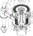
Fig. 2 is a perspective view of fig. 1.
Fig. 3 is a partially enlarged view of a portion a in fig. 2.
Fig. 4 is a schematic view of a second embodiment of the combined dust removing device of the present invention.
FIG. 5 is a sectional view of the cylinder of the industrial centrifugal separator placed horizontally.
FIG. 6 is a front view of a first embodiment of the industrial centrifugal separator of the present invention.
Fig. 7 is a perspective exploded view of fig. 6.
Fig. 8 is an enlarged view of the dust ring and central support portion of fig. 7.
FIG. 9 is a front view of a second embodiment of the industrial centrifugal separator of the present invention.
FIG. 10 is a front view of a third embodiment of the industrial centrifugal separator of the present invention.
FIG. 11 is a front view of a fourth embodiment of the industrial centrifugal separator of the present invention.
FIG. 12 is a front view of a fifth embodiment of the industrial centrifugal separator of the present invention.
FIG. 13 is a front view of a sixth embodiment of the industrial centrifugal separator of the present invention.
In the figure: 1. a barrel; 1a, a settling chamber; 1b, a dust discharging port of the machine barrel; 1c, arc-shaped baffles; 2. an air inlet section; 2a, an air inlet section central seat; 2b, air inlet guide vanes; 2c, a flow guide sleeve; 3. an air inlet impeller; 3a, air inlet impeller outer grooves; 4. a central shaft; 4a, a coupler; 5. an air exhaust section; 5a, an exhaust section center seat; 5b, air exhaust guide vanes; 5c, a protective net; 6. an exhaust impeller; 6a, inner flash of the exhaust impeller; 6b, an exhaust impeller center seat; 7. a dust catching ring; 7a, a dust catching ring rib; 7b, embedding a dust catching ring in the groove; 7c, forming an outer groove of the dust catching ring; 8. a central support; a stent central cylinder; 8b. a center barrel web; 8c, a bracket lower flange; 8d, a bracket middle flange; 8e, an upper flange of the bracket; 9. sealing the swivel; 9a. swivel blades; 10. a wind-shield ring; 10a, a wind-break ring flange; 10b, a wind-shield ring; 11. a motor; 12. a saxolone; 13. connecting an air pipe; 14. an exhaust gas duct; 15. separating the impeller; separating the impeller central cylinder; 15b, separating the blades; 15c, separating the lower flange of the impeller; 15d, reinforcing rings; and 15e, separating the upper flange of the impeller.
Detailed Description
In the following description of the present invention, the terms "upper", "lower", "front", "rear", "left", "right", "inner", "outer", etc., indicate orientations or positional relationships based on those shown in the drawings, and are only for convenience in describing the present invention and simplifying the description, but do not mean that the system must have a specific orientation.
As shown in fig. 1 to fig. 3, the industrial centrifugal dust collector in the combined dust collector of the present invention can be vertically placed, the lower port of the air intake section 2 is connected to the exhaust air duct 14, the dust exhaust port 1b of the machine barrel is connected to the air intake of the salon 12, and the air outlet at the top of the salon 12 is connected to the exhaust air duct 14 through the connecting air duct 13. The particles discharged from the dust discharge port 1b of the machine barrel enter the cyclone 12 along the horizontal tangential direction for further separation and collection, the particles are discharged from the bottom outlet of the cyclone 12, the tail gas is discharged from the top of the cyclone 12, returns to the waste gas air pipe 14 through the connecting air pipe 13, and then enters the industrial centrifugal dust collector again for separation. Not only is convenient for collecting and discharging fine particles, but also avoids the emission of the tail gas of the saxolone, and is beneficial to protecting the environment; if the fine particles are expensive materials, the recovery rate of the materials can be improved, and the cost is saved.
As shown in FIG. 4, the industrial centrifugal dust collector in the combined dust collector of the present invention can also be placed horizontally, i.e. the machine barrel 1 is placed horizontally, the air intake section 2 is connected with the exhaust air duct 14, the dust exhaust port 1b of the machine barrel is located at the lower part of the circumference of the machine barrel and extends tangentially and is connected with the air intake of the salon 12, and the air outlet at the top of the salon 12 is connected with the exhaust air duct 14 through the connecting air duct 13. The small particles are discharged from a dust discharge port 1b of the machine barrel at the lower part of the machine barrel 1 along the tangential direction, enter the sand-controlled dragon 12 for further separation and collection, the particles are discharged from a bottom outlet of the sand-controlled dragon 12, the tail gas is discharged from the top of the sand-controlled dragon 12, returns to an exhaust gas air pipe 14 through a connecting air pipe 13, and then enters the industrial centrifugal dust collector again for separation. For the gas with higher moisture content, the liquid drops are convenient to collect at the bottom of the circumference of the cylinder 1 and then flow into the dust discharge port 1b of the cylinder for discharge.
As shown in fig. 6 to 9, the industrial centrifugal dust collector includes an air intake section 2, a machine barrel 1 and an air exhaust section 5 which are connected in sequence, the air intake section 2 is connected to the lower end of the machine barrel 1, a rotor is installed along the axis of the machine barrel 1, an air intake impeller 3, a centrifugal dust catching device and an air exhaust impeller 6 are sequentially arranged on a central shaft 4 of the rotor along the air flow direction, the air intake impeller 3 is located in the air intake section 2, the centrifugal dust catching device is located in the machine barrel 1, the air exhaust impeller 6 is located in the air exhaust section 5, a motor 11 is installed at the outlet of the air exhaust section 5, and the output end of the motor 11 is connected with the upper end of the central shaft 4 through a coupling 4a. An annular settling chamber 1a is arranged between the outer edge of the centrifugal dust catching device and the inner wall of the machine barrel, and the upper circumference of the machine barrel 1 is tangentially connected with a machine barrel dust discharging port 1b.
The central shaft 4 drives the air inlet impeller 3, the centrifugal dust catching device and the air exhaust impeller 6 to rotate at a high speed, the suction force generated by the air inlet impeller 3 enables the dust-containing gas to enter the air inlet section 2, after the dust-containing gas is accelerated by the air inlet impeller 3, the dust-containing gas flows upwards along the axial direction while rotating, enters the inner cavity of the machine barrel 1 and flows through the centrifugal dust catching device, the dust-containing gas performs high-speed circular motion under the rotation driving of the centrifugal dust catching device to generate huge centrifugal force, tiny solid particles or small droplets in the dust-containing gas are thrown into the settling chamber 1a under the action of the centrifugal force, and are finally discharged from the tail end of the airflow advancing direction, namely a machine barrel dust discharging port 1b on the upper circumference of the machine barrel 1, the clean gas passes through the centrifugal dust catching device to continuously flow upwards to enter the air exhaust section 5 and is discharged from the upper port of the air exhaust section 5 under the action of the air exhaust impeller 6. In the invention, the gas passes through the air inlet impeller 3, the centrifugal dust collecting device and the air exhaust impeller 6 in sequence, the rotating speed of circular motion generated in the machine barrel 1 is high, the centrifugal force is large, the dust and gas separation effect is good, and the dust removal efficiency is high.
The centrifugal dust catching device comprises a plurality of dust catching rings 7 which are arranged at equal intervals along the axial direction of the machine barrel, and each dust catching ring 7 is in a conical ring shape with a large upper part and a small lower part.
As shown in fig. 6, each dust-catching ring 7 may be of a sheet pile structure, a plurality of dust-catching ring ribs 7a extending in the radial direction may be uniformly distributed on the upper end surface or the lower end surface of each dust-catching ring 7, and each dust-catching ring rib 7a is pressed on the adjacent dust-catching ring; the inner edges of the dust catching rings 7 are respectively fixed on a central support 8, the lower end of the central support 8 is fixedly connected with the back of the air inlet impeller 3, and the center of the upper end of the central support 8 is fixed on the central shaft 4. Each dust catching ring 7 can be sleeved outside the central support 8, and the convex edge 7a of each dust catching ring presses on the adjacent dust catching ring, so that the axial positioning of each dust catching ring 7 is realized, and the equal distance between the adjacent dust catching rings 7 is ensured.
The central bracket 8 is fixed on the central shaft 4, so that when the central shaft 4 rotates, the central bracket 8 drives each dust catching ring 7 to synchronously rotate at the same angular speed omega; the distance H between each dust catching ring 7 is only a plurality of times of the total height H of the settling chamber 1a, each dust catching ring 7 is in a shape of a cone with a large top and a small bottom, dust-containing gas flows downwards along a gap between two adjacent dust catching rings 7 centripetally, so that short flow is avoided on one hand, and on the other hand, dust only needs to reach the cone wall of the dust catching ring 7 through a short distance, primary separation from gas is realized, and the settling separation speed is greatly accelerated.
In addition, when the dust catching rings 7 rotate at a high speed, the speed difference between the gas farther away from the dust catching rings 7 and the dust catching rings 7 is larger, and in the invention, because the distance between two adjacent dust catching rings 7 is small, the high-speed rotation of the dust catching rings 7 can drive the gas in the gap to rotate at the angular speed omega almost the same as that of the dust catching rings 7, the larger the angular speed omega of the gas rotation is, the larger the generated centrifugal force is, the more easily the dust is separated out due to the action of inertia and centrifugal force, and the higher the dust removal efficiency is.
The central support 8 comprises a closed support central cylinder 8a, the lower part of the middle part of the support central cylinder 8a can be gradually enlarged to form a bell mouth shape, a plurality of radial and outward extending central cylinder radial plates 8b are uniformly distributed on the periphery of the support central cylinder 8a, the lower edge of each central cylinder radial plate 8b and the lower port of the support central cylinder 8a are both connected to a support lower flange 8c, and the support lower flange 8c is fixedly connected to a convex ring on the back of the air inlet impeller 3; each dust catching ring 7 is sleeved on the periphery of a central cylinder radial plate 8b, the inner edge of each dust catching ring 7 is provided with at least one dust catching ring embedding groove 7b which is sunken inwards along the axis of a dust catching ring convex edge 7a, the correspondingly widened central cylinder radial plate 8b is embedded in the dust catching ring embedding groove 7b, and the outer edges of the other central cylinder radial plates 8b abut against the inner edge of the dust catching ring 7.
The central cartridge webs 8b provide support for the dust ring 7 and channels for the upward flow of clean gas are formed between adjacent central cartridge webs 8b. The lower flange 8c of the bracket is fixed on the convex ring at the back of the air inlet impeller 3, so that the rigidity and the strength of the lower flange and the convex ring are increased, and the axial positioning is realized together. One, two or more pairs of widened central cylinder radial plates 8b are respectively embedded in the corresponding dust catching ring embedding grooves 7b, so that the radial positioning of each dust catching ring 7 on the central support 8 is realized, and the relative rotation between each dust catching ring 7 and the central support 8 is ensured.
A plurality of dust catching ring outer grooves 7c which are sunken towards the axial direction can be uniformly distributed on the outer edge of each dust catching ring 7, and each dust catching ring outer groove 7c can be respectively positioned between the outer ends of two adjacent central cylinder radial plates 8b.
A plurality of air inlet impeller outer grooves 3a which are sunken towards the axis direction can be uniformly distributed on the outer circumference of the air inlet impeller 3, and each air inlet impeller outer groove 3a can be respectively positioned between two adjacent air inlet blades.
The dust settled on the dust-catching ring 7 is gathered at the root of the convex rib 7a of the dust-catching ring and centrifugally moves outwards along the convex rib 7a of the dust-catching ring under the action of centrifugal force; the gas directly enters the gap between two adjacent dust catching rings 7 from the outer groove 7c of each dust catching ring and flows downwards centripetally, so that the resistance at the turning position of the outer edge of each dust catching ring is greatly reduced, the paths are not interfered with each other although the moving direction of the dust is opposite, the wind resistance is reduced, and the dust removal effect is further improved. In the same way, the air flow can directly turn upwards at the outer groove 3a of each air inlet impeller to enter the inner cavity of the machine barrel 1, so that the interference of the air flow and the dust discharged from the dust catching ring is reduced, and the separation efficiency is improved.
The back plate of the air inlet impeller 3 is conical, the inclination angle of the back plate is the same as or close to that of the dust catching ring 7, the convex edge 7a of the dust catching ring at the bottom layer is directly or indirectly pressed on the back plate of the air inlet impeller 3, and the center of the lower end of the back plate of the air inlet impeller is fixed on the boss of the central shaft 4. Not only the axial fixation between the bottom dust catching ring 7 and the air inlet impeller 3 is realized, but also the bottom dust catching ring 7 has the same sedimentation environment as the upper dust catching ring, and the function of a sedimentation space is fully exerted.
As shown in fig. 9, each dust ring 7 is welded, riveted or otherwise fixedly connected to a central support 8, the central support 8 comprises a closed support central cylinder 8a, and the support central cylinder 8a is fixed to the rotor. Each dust collecting ring 7 is fixedly connected with the central support 8 to form a whole pile structure with equal intervals, so that the dynamic balance of the rotor can be corrected outside the machine conveniently, and the installation and maintenance are facilitated.
The rotor is provided with a sealing rotating ring 9, the sealing rotating ring 9 is positioned between the centrifugal dust catching device and the exhaust impeller 6, the outer edge of the sealing rotating ring 9 is close to the inner wall of the machine barrel 1, the sealing rotating ring 9 is in a conical shape with a large top and a small bottom, and a plurality of rotating ring blades 9a are uniformly distributed on the upper end surface of the sealing rotating ring 9.
Each central cylinder radial plate 8b can be step-shaped, the middle part of the outer edge of each central cylinder radial plate 8b can be connected to the support middle flange 8d, and the support upper flange 8e and the support middle flange 8d can improve the strength of the central cylinder radial plate 8b, so that the central support 8 becomes a rigid integral structure. The upper end of the outer edge of each central barrel web 8b may be attached to a bracket upper flange 8e. The sealing rotary ring 9 can be fixed on a flange 8d in the bracket, and the lower end surface of the sealing rotary ring 9 can be directly or indirectly pressed on the top dust catching ring.
The sealing rotary ring 9 is arranged above the dust-catching ring 7, which can prevent dust in the settling chamber 1a from entering the air exhaust section 5 upwards and prevent clean air entering the air exhaust section 5 upwards along the outer wall of the central cylinder 8a of the bracket from being polluted again. Each of the rotary ring vanes 9a rotates with the sealing rotary ring 9 to generate an air flow in the direction of the vane toward the outer edge, and more effectively prevent dust from reaching the upper end face of the sealing rotary ring 9 or flowing toward the center along the upper end face of the sealing rotary ring 9.
A wind-shielding ring 10 is arranged between the exhaust impeller 6 and the sealing rotary ring 9, the wind-shielding ring 10 extends along the axial direction of the lower end surface of the exhaust impeller 6 towards the central shaft 4, the outer edge of the wind-shielding ring 10 can be welded on the inner wall of the machine barrel 1 or the exhaust section 5, the wind-shielding ring 10 can be formed by inwards bending the lower edge of the exhaust section 5, a wind-shielding ring flange 10a can be arranged at the upper end of the wind-shielding ring 10, and the wind-shielding ring flange 10a is fixed between the upper flange of the machine barrel and the lower flange of the exhaust section. The inner edge of the wind-shield ring 10 is deeply inserted into a position close to the central seat 6b of the exhaust impeller or the central cylinder of the bracket, firstly a labyrinth-like sealing structure is formed at the position, secondly, a small enough gap is kept between the sealing rotating ring 9 and one end of the exhaust impeller 6, collision is avoided in the operation process, and meanwhile, the small gap can reduce the amount of clean air flowing back into the machine barrel and reduce the loss of the air handling capacity of the exhaust impeller 6; because of the pumping action of the sealing rotary ring 9, centripetal airflow can be generated on the upper end face of the wind-shield ring 10, and the lower end face of the wind-shield ring 10 is centrifugal outward airflow, so that the possibility of dust leakage from the wind-shield ring is completely eliminated.
The exhaust impeller 6 can be sleeved on the outer edge of the upper part of each central tube radial plate 8b, the bottom of the exhaust impeller 6 is provided with an exhaust impeller central seat 6b, the bottom of the exhaust impeller central seat 6b is pressed at the center of the sealing rotating ring 9, the inner edge of the top of the exhaust impeller 6 is provided with an exhaust impeller inner flange 6a which extends inwards, and the exhaust impeller inner flange 6a is fixed on a bracket upper flange 8e. After the exhaust impeller 6 is sleeved on the upper part of the central cylinder radial plate 8b, the inner flange 6a of the exhaust impeller is pressed on the upper flange 8e of the bracket and is fixedly connected through a screw, so that the exhaust impeller 6 and the sealing rotary ring 9 are reliably positioned on the central bracket 8, and the exhaust impeller has high integral strength and good rigidity.
The upper center of the air exhaust section 5 is provided with an air exhaust section center seat 5a, the periphery of the air exhaust section center seat 5a is connected with the inner wall of the air exhaust section 5 through a plurality of air exhaust guide vanes 5b, the upper end of the central shaft 4 is fixed in the air exhaust section center seat 5a through a bearing, and the outer port of the air exhaust section 5 is covered with a protective net 5c. The air exhaust guide vane 5b plays a role of a reinforcing rib, and the strength of the central seat 5a of the air exhaust section is improved so as to bear the weight of the upper motor 11 and the whole rotor; and the air can be guided, the flow resistance is reduced, and the air flows upwards along the axial direction.
The upper cylinder wall of the air inlet section 2 is conical with a large upper part and a small lower part and is matched with the outer edge of the air inlet impeller 3, the lower part of the air inlet section 2 is cylindrical, an air inlet section center seat 2a is arranged at the center of the air inlet section 2, the periphery of the air inlet section center seat 2a is connected with the cylinder wall of the air inlet section 2 through a plurality of air inlet guide vanes 2b, and the lower end of a center shaft 4 is supported on the air inlet section center seat 2a through a bearing. When air flow enters the air inlet section 2, the air flow is guided by the air inlet guide vanes 2b to generate a certain rotating speed, so that the energy consumption of the air inlet impeller 3 can be reduced; meanwhile, the air inlet guide vanes 2b also play a role of reinforcing ribs, and the connection strength of the air inlet section 2 and the air inlet section center seat 2a is improved.
The lower end face of the air inlet section center seat 2a is fixed with a flow guide cover 2c, and the head of the smooth tip of the flow guide cover 2c can further reduce the resistance when the airflow enters the air inlet section 2.
As shown in fig. 10, the centrifugal dust catching device is a separation impeller 15, the separation impeller 15 includes a closed separation impeller center cylinder 15a, a plurality of separation blades 15b extending radially outward are uniformly distributed on the periphery of the separation impeller center cylinder 15a, the lower end of the separation impeller center cylinder 15a is fixedly connected to the back of the air intake impeller 3, the upper end of the separation impeller center cylinder 15a is fixed on the center shaft 4, and the upper circumference of the cylinder 1 is tangentially connected with a cylinder dust discharge port 1b.
The dust-containing gas is driven by the rotation of the separation impeller 15 to perform high-speed circular motion to generate huge centrifugal force, tiny solid particles or small droplets in the dust-containing gas are thrown into the sedimentation cavity 1a under the action of the centrifugal force and are finally discharged from the machine barrel dust discharge port 1b on the upper circumference of the machine barrel 1, and the clean gas continuously flows upwards along the channel between the separation blades 15b and the outer wall of the separation impeller central barrel 15a to enter the exhaust impeller 6 and is discharged from the upper port of the exhaust section 5 under the action of the exhaust impeller 6.
The sealing rotary ring 9 is positioned between the separating impeller 15 and the exhaust impeller 6, and the outer edge of the sealing rotary ring 9 is close to the inner wall of the machine barrel 1. Each of the separation blades 15b may have a stepped shape with a narrow top and a wide bottom, and the sealing swivel 9 may be installed at a middle step of the separation blade 15b.
A plurality of rotating ring blades 9a are uniformly distributed on the upper end face of the sealing rotating ring 9, the outer edge of the upper end of each separating blade 15b is connected to an upper flange 15e of the separating impeller, the exhaust impeller 6 is sleeved on the outer edge of the upper part of each separating blade 15b, an exhaust impeller center seat 6b is arranged at the bottom of the exhaust impeller 6, the bottom of the exhaust impeller center seat 6b is pressed at the center of the sealing rotating ring 9, an exhaust impeller inner flange 6a extending inwards is arranged on the inner edge of the top of the exhaust impeller 6, and the exhaust impeller inner flange 6a is fixed on the upper flange 15e of the separating impeller. The separation impeller upper flange 15e can improve the strength of the separation blade 15b, so that the separation impeller 15 becomes a rigid integral structure; after the exhaust impeller 6 is sleeved on the upper part of the separation blade 15b, the inner flange 6a of the exhaust impeller is pressed on the upper flange 15e of the separation impeller and is fixedly connected with the upper flange through a screw, so that the exhaust impeller 6 and the sealing rotating ring 9 are reliably positioned on the separation impeller 15, and the exhaust impeller is high in integral strength and good in rigidity.
A wind shield ring 10 is arranged between the exhaust impeller 6 and the sealing rotary ring 9, and the wind shield ring 10 extends along the lower end surface of the exhaust impeller 6 to the periphery of the exhaust impeller center seat 6b.
As shown in fig. 10, the upper end of the wind deflector 10 may be provided with a wind deflector flange 10a, and the wind deflector flange 10a is fixed between the upper flange of the cylinder and the lower flange of the exhaust section. The outer edge of the wind shielding ring 10 can be welded on the inner wall of the machine barrel 1 or the exhaust section 5.
The lower edge of each separation blade 15b and the lower port of the separation impeller central cylinder 15a are both connected to a separation impeller lower flange 15c, and the separation impeller lower flange 15c is fixedly connected to a convex ring on the back of the air inlet impeller 3. The lower flange 15c of the separation impeller and the convex ring fixed on the back of the air inlet impeller 3 increase the rigidity and the strength of the lower flange and the convex ring, and realize axial positioning together.
As shown in fig. 10, 11 and 12, at least one reinforcing ring 15d may be provided along the height direction of the separation blade 15b to improve the strength and rigidity of the separation impeller 15, the outer edge of each separation blade 15b may be welded to each reinforcing ring 15d, and the inner edge of each separation blade 15b may be connected to the outer wall of the separation impeller central cylinder 15a.
FIG. 11 shows a fourth embodiment of the industrial dust collector, in which the centrifugal dust-collecting device is a separating impeller 15, a wind-blocking ring 10 is arranged above the rotating ring blade 9a of the sealing rotating ring 9, the wind-blocking ring 10 is formed by bending the lower end of the air-exhausting section inwards, and the inner edge of the wind-blocking ring 10 is inserted below the air-exhausting impeller; the inner wall of the upper part of the machine barrel is connected with an arc baffle plate 1c which is bent towards the outer end of the sealing rotating ring 9, and the upper end of the arc baffle plate 1c is welded at the bottom of the wind blocking ring 10. The wind-blocking ring 10 is formed by bending the lower end of the air exhaust section inwards and is inserted below the air exhaust impeller, and smooth arc transition is formed at the outlet of the air exhaust impeller, so that the air outlet resistance of the air exhaust impeller can be reduced; a small enough gap is kept between the upper end surface of the wind shield ring 10 and the exhaust impeller, and a small enough gap is kept between the lower end surface of the wind shield ring 10 and the rotating ring blade 9a of the sealing rotating ring 9, so that collision is avoided in the operation process, and meanwhile, the small gap can reduce the amount of clean air flowing back into the machine barrel and reduce the loss of the air handling capacity of the exhaust impeller; because of the pumping action of the sealing rotary ring 9, centripetal airflow can be generated on the upper end face of the wind-shield ring 10, and the lower end face of the wind-shield ring 10 is centrifugal outward airflow, so that the possibility of dust leakage from the wind-shield ring is completely eliminated. The arc-shaped baffle 1c on the inner wall of the upper part of the machine barrel can seal a triangular area below the root part of the wind-blocking ring 10, so that dust is prevented from being deposited inside the arc-shaped baffle, and the arc-shaped baffle can form good matching with the outer edge of the rotating ring blade 9a.
Fig. 12 shows an embodiment of an industrial dust collector, in which the centrifugal dust collecting device is a separating impeller 15, a wind-blocking ring 10b is arranged above a rotating ring blade 9a of the sealing rotating ring 9, the inner edge of the wind-blocking ring 10b is connected with the inner edge of the wind-blocking ring 10 into a whole, the wind-blocking ring 10 extends along the lower part of the exhaust impeller, and the outer edge of the wind-blocking ring 10b or the wind-blocking ring 10 is fixed on the machine barrel. The inner edge of the wind shield ring 10 is deeply inserted into a position close to a central seat of the exhaust impeller, a labyrinth-like sealing structure is formed at the position, a small enough gap is kept between the upper end surface of the wind shield ring 10 and the exhaust impeller, a small enough gap is kept between the lower end surface of the wind shield ring 10b and a rotating ring blade 9a of the sealing rotating ring 9, collision is avoided in the operation process, meanwhile, the small gap can reduce the amount of clean air flowing back into a machine barrel, and the loss of the air treatment amount of the exhaust impeller is reduced; because of the pumping action of the sealing rotating ring 9, centripetal airflow can be generated on the upper end face of the wind shield ring 10, and the lower end face of the wind shield ring 10b is centrifugal outward airflow, so that the possibility of dust leakage from the wind shield ring is completely eliminated.
Fig. 13 shows the separating impeller 15 in the sixth embodiment of the industrial dust collector, and the separating impeller 15 may have a part of the separating blades 15b only welded to the reinforcing ring 15d, and the inner edges of the other part of the separating blades 15b spaced at equal intervals extend to the outer wall of the central tube 15a of the separating impeller and are welded to each other, so that the separating effect of the exhaust impeller 15 can be improved and the weight can be reduced.
The above description is only a preferred embodiment of the present invention, and not intended to limit the scope of the present invention. In addition to the above embodiments, the present invention may have other embodiments. All technical solutions formed by adopting equivalent substitutions or equivalent transformations fall within the protection scope of the claims of the present invention. Technical features of the present invention which are not described may be implemented by or using the prior art, and will not be described herein.
Claims (7)
1. The utility model provides a modular dust collector, includes the husky dragon, its characterized in that: the device is characterized by also comprising an industrial centrifugal dust remover, wherein an air inlet of the industrial centrifugal dust remover is connected with a waste gas air pipe, a machine barrel dust exhaust port of the industrial centrifugal dust remover is connected with an air inlet of the cyclone, and an air outlet at the top of the cyclone is connected with the waste gas air pipe through a connecting air pipe; the industrial centrifugal dust collector is horizontally or vertically placed, and when the industrial centrifugal dust collector is vertically placed, the central line of the industrial centrifugal dust collector extends along the vertical direction; when the centrifugal dust remover is placed horizontally, the dust discharge port of the machine barrel is positioned at the lower part of a settling chamber of the industrial centrifugal dust remover; the industrial centrifugal dust collector comprises a machine barrel, wherein an air inlet section is arranged at the lower end of the machine barrel, an air exhaust section is arranged at the upper end of the machine barrel, a rotor is installed along the axis of the machine barrel, an air inlet impeller, a centrifugal dust catching device and an air exhaust impeller are sequentially arranged on a central shaft of the rotor along the air flow direction, the air inlet impeller is positioned in the air inlet section, the centrifugal dust catching device is positioned in the machine barrel, the air exhaust impeller is positioned in the air exhaust section, and a machine barrel dust exhaust port is tangentially connected to the circumference of the upper part of the machine barrel; the centrifugal dust catching device comprises a plurality of dust catching rings which are arranged at equal intervals along the axial direction of the machine barrel, and each dust catching ring is in a conical ring shape with a large upper part and a small lower part; the back plate of the air inlet impeller is conical, and the inclination angle of the back plate is the same as or similar to that of the dust catching ring; the centrifugal dust collecting device is characterized in that a sealing rotating ring is mounted on the rotor and located between the centrifugal dust collecting device and the exhaust impeller, the outer edge of the sealing rotating ring is close to the inner wall of the machine barrel, the sealing rotating ring is in a conical shape with a large upper part and a small lower part, and a plurality of rotating ring blades are uniformly distributed on the upper end face of the sealing rotating ring to generate outward sealing air flow.
2. The combined dust extraction device of claim 1, wherein: a plurality of dust catching ring convex edges extending along the radial direction are uniformly distributed on the upper end surface or the lower end surface of each dust catching ring, and each dust catching ring convex edge is pressed on the adjacent dust catching rings respectively; the inner edges of the dust catching rings are respectively fixed on a central bracket, and the central bracket is fixed on a central shaft or between an air inlet impeller and an air exhaust impeller.
3. The combined dust extraction device of claim 2, wherein: the central support comprises a closed support central cylinder, a plurality of radially and outwardly extending central cylinder radial plates are uniformly distributed on the periphery of the support central cylinder, and the lower end of each support central cylinder is fixedly connected to the back of the air inlet impeller; each dust catching ring is sleeved on the periphery of the radial plate of the central cylinder, the inner edge of each dust catching ring is provided with at least one dust catching ring embedding groove which is inwards sunken along the axis of the convex edge of the dust catching ring, the correspondingly widened radial plate of the central cylinder is embedded in the dust catching ring embedding groove, and the outer edges of the radial plates of the other central cylinders are propped against the inner edge of the dust catching ring.
4. The combined dust extraction device of claim 1, wherein: the outer edge of each dust catching ring is uniformly distributed with a plurality of dust catching ring outer grooves sunken towards the axis direction, and the outer circumference of the air inlet impeller is uniformly distributed with a plurality of air inlet impeller outer grooves sunken towards the axis direction.
5. The combined dust extraction device of claim 1, wherein: and a fixed wind-shielding ring is arranged between the exhaust impeller and the rotating ring blade of the sealing rotating ring, and the inner edge of the wind-shielding ring extends towards the direction of the central shaft.
6. The combined dust extraction device of claim 1, wherein: each dust catching ring is fixedly connected to a central support in a welding, riveting or other mode, the central support comprises a closed support central cylinder, and the support central cylinder is fixed to the rotor.
7. The combined dust extraction device of any one of claims 1 to 6, wherein: an air exhaust section center seat is arranged at the center of the upper part of the air exhaust section, the upper end of the center shaft is fixed in the air exhaust section center seat through a bearing, and a plurality of air exhaust guide vanes are distributed between the periphery of the air exhaust section center seat and the inner wall of the air exhaust section.
Priority Applications (1)
| Application Number | Priority Date | Filing Date | Title |
|---|---|---|---|
| CN201811557775.3A CN109351060B (en) | 2018-12-19 | 2018-12-19 | Combined dust removing device |
Applications Claiming Priority (1)
| Application Number | Priority Date | Filing Date | Title |
|---|---|---|---|
| CN201811557775.3A CN109351060B (en) | 2018-12-19 | 2018-12-19 | Combined dust removing device |
Publications (2)
| Publication Number | Publication Date |
|---|---|
| CN109351060A CN109351060A (en) | 2019-02-19 |
| CN109351060B true CN109351060B (en) | 2021-07-23 |
Family
ID=65329218
Family Applications (1)
| Application Number | Title | Priority Date | Filing Date |
|---|---|---|---|
| CN201811557775.3A Active CN109351060B (en) | 2018-12-19 | 2018-12-19 | Combined dust removing device |
Country Status (1)
| Country | Link |
|---|---|
| CN (1) | CN109351060B (en) |
Citations (7)
| Publication number | Priority date | Publication date | Assignee | Title |
|---|---|---|---|---|
| CN201049276Y (en) * | 2007-06-01 | 2008-04-23 | 席玉林 | Centrifugal filtering composite dust-removing device |
| CN201618621U (en) * | 2010-03-07 | 2010-11-03 | 溧阳正昌干燥设备有限公司 | Cyclone centrifugal dust collection device |
| CN101972716A (en) * | 2010-09-27 | 2011-02-16 | 华中科技大学 | Gas-solid centrifugal separation and exhaust integrated machine |
| US20110296648A1 (en) * | 2007-03-02 | 2011-12-08 | Kah Jr Carl L C | Centrifugal dirt separation configurations for household-type and shop-type vacuum cleaners |
| CN103041936A (en) * | 2011-10-15 | 2013-04-17 | 高苏茂 | Vortex acceleration dust collector |
| CN103842091A (en) * | 2011-09-27 | 2014-06-04 | 伟尔矿物澳大利亚私人有限公司 | Centrifugal screen apparatus |
| CN204745982U (en) * | 2015-05-21 | 2015-11-11 | 杨柳清 | Dust collecting equipment |
Family Cites Families (7)
| Publication number | Priority date | Publication date | Assignee | Title |
|---|---|---|---|---|
| US6277163B1 (en) * | 1999-04-06 | 2001-08-21 | Oreck Holdings Llc | Vacuum cleaner outer bag |
| WO2011112872A2 (en) * | 2010-03-12 | 2011-09-15 | Levitt David J | Fluid filtration and particle concentration device and methods |
| JP5530316B2 (en) * | 2010-09-09 | 2014-06-25 | アマノ株式会社 | Oil mist removal device |
| EP2735351B1 (en) * | 2012-11-23 | 2014-12-31 | Alfa Laval Corporate AB | Centrifugal separator for separating particles from a gas stream |
| KR101465022B1 (en) * | 2014-05-12 | 2014-11-27 | 이상필 | Purification apparatus for compressed air |
| KR102176885B1 (en) * | 2015-01-19 | 2020-11-10 | 엘지전자 주식회사 | Dust collector for vacuum cleaner |
| CN106238231B (en) * | 2016-09-19 | 2018-07-13 | 长沙学院 | A kind of bipyramid cylinder cyclone dust collector |
-
2018
- 2018-12-19 CN CN201811557775.3A patent/CN109351060B/en active Active
Patent Citations (7)
| Publication number | Priority date | Publication date | Assignee | Title |
|---|---|---|---|---|
| US20110296648A1 (en) * | 2007-03-02 | 2011-12-08 | Kah Jr Carl L C | Centrifugal dirt separation configurations for household-type and shop-type vacuum cleaners |
| CN201049276Y (en) * | 2007-06-01 | 2008-04-23 | 席玉林 | Centrifugal filtering composite dust-removing device |
| CN201618621U (en) * | 2010-03-07 | 2010-11-03 | 溧阳正昌干燥设备有限公司 | Cyclone centrifugal dust collection device |
| CN101972716A (en) * | 2010-09-27 | 2011-02-16 | 华中科技大学 | Gas-solid centrifugal separation and exhaust integrated machine |
| CN103842091A (en) * | 2011-09-27 | 2014-06-04 | 伟尔矿物澳大利亚私人有限公司 | Centrifugal screen apparatus |
| CN103041936A (en) * | 2011-10-15 | 2013-04-17 | 高苏茂 | Vortex acceleration dust collector |
| CN204745982U (en) * | 2015-05-21 | 2015-11-11 | 杨柳清 | Dust collecting equipment |
Also Published As
| Publication number | Publication date |
|---|---|
| CN109351060A (en) | 2019-02-19 |
Similar Documents
| Publication | Publication Date | Title |
|---|---|---|
| US4382804A (en) | Fluid/particle separator unit and method for separating particles from a flowing fluid | |
| CN102878115B (en) | Chip purges and/or aspirator | |
| EP0053508B1 (en) | Improved fluid/particle separator apparatus | |
| HU219928B (en) | Device for separating solid or liquid particles from a stream of gas | |
| CN109351059B (en) | Industrial centrifugal dust remover | |
| CN113181715A (en) | Internal and external cyclone reverse shunting type air dust removal method and device | |
| CN109351060B (en) | Combined dust removing device | |
| CN215227223U (en) | A separation module and cleaning machine for cleaning machine | |
| CN212820529U (en) | Cyclone dust collector | |
| CN207520098U (en) | Dust collect plant and dust catcher | |
| CN209348264U (en) | A kind of industrial centrifugal deduster | |
| CN114289196B (en) | High-efficiency cyclone dust collector | |
| CN203540242U (en) | Separating pulse dust remover of high concentration dust | |
| CN202900590U (en) | Inlet filtering device for air compressor | |
| CN209438215U (en) | A kind of industrial dust collector | |
| CN209915869U (en) | Dust collecting device and dust collector | |
| CN209076931U (en) | A kind of thermosetting powder coating micro mist disintegrating apparatus cyclone separator | |
| CN211302504U (en) | Multi-air-duct comprehensive dust removal system | |
| CN113273924A (en) | Garbage separator and vacuum cleaner | |
| CN107781874B (en) | Kitchen ventilator displacement configuration and kitchen ventilator | |
| JP2001317785A (en) | Ventilating device | |
| CN107917452B (en) | Kitchen ventilator displacement configuration and kitchen ventilator | |
| JP2010279910A (en) | Apparatus for removing oil mist | |
| WO2019230258A1 (en) | Separation device | |
| CN112354309B (en) | Oil smoke separator and range hood applying same |
Legal Events
| Date | Code | Title | Description |
|---|---|---|---|
| PB01 | Publication | ||
| PB01 | Publication | ||
| SE01 | Entry into force of request for substantive examination | ||
| SE01 | Entry into force of request for substantive examination | ||
| GR01 | Patent grant | ||
| GR01 | Patent grant |